

Page 1

Giga-tronics ASCOR SERIES 8000 Getting Started Guide Rev. C
GIGA-TRONICS
Giga-tronics ASCOR
Series 8000 Switch
Getting Started Guide
Terukuni Okuyama
2013-08-14
This guide describes the installation, controlling, and programming of the Series 8000 Switch
Module.
Getting Started Guide, Part Number 07507593, Rev C, August 14, 2013
1 of 38
Page 2

Giga-tronics ASCOR SERIES 8000 Getting Started Guide Rev. C
1. OVERVIEW .......................................................................................................................... 5
2. INSTALLING SERIES 8000 GUI PROGRAM, I/O AND USB DRIVER .................... 6
2.1 Installing Series 8000 GUI Program and I/O Driver .......................................................................... 6
2.1.1 Setup Opening Panel ................................................................................................................... 6
2.1.2 Destination Directory Panel ........................................................................................................ 7
2.1.3 License Agreement Panel ............................................................................................................ 7
2.1.4 Start Installation Panel ................................................................................................................ 8
2.1.5 Installation Complete Panel ........................................................................................................ 8
2.2 Installing the USB Device Driver ...................................................................................................... 9
3. STARTING THE SERIES 8000 GUI PROGRAM ....................................................... 11
3.1 Main Panel - Initialization Tab ...................................................................................................... 11
3.1.1 Live Mode .................................................................................................................................. 12
3.1.2 Simulation Mode ....................................................................................................................... 14
3.2 Main Panel - Switch Control Tab ................................................................................................... 15
3.2.1 Closing and Opening Switches using Virtual LEDs ..................................................................... 16
3.2.2 Closing and Opening Switches using Numerical Controls ......................................................... 16
3.2.3 Switch Access Count Indicators ................................................................................................. 16
3.3 Main Panel - Switch Table Tab ...................................................................................................... 17
3.4 Communication Panel ................................................................................................................... 18
4. CONNECTING TO LAN-BASE SERIES 8000 SWITCH FOR THE FIRST TIME . 19
4.1 Equipment needed ....................................................................................................................... 19
4.2 Connecting to the Series 8000 Switch ........................................................................................... 19
4.3 Matching Your Computer’s IP Address to the Series 8000 Switch ................................................. 20
5. CHANGING THE IP ADDRESS OF THE SERIES 8000 SWITCH .......................... 21
5.1 Welcome Web Page ...................................................................................................................... 21
5.2 Configuration Web Page ............................................................................................................... 22
5.3 Other Configuration Web Page Settings: ....................................................................................... 22
5.4 Confirmation Web Page ................................................................................................................ 23
5.5 Rebooting Web Page .................................................................................................................... 24
Getting Started Guide, Part Number 07507593, Rev C, August 14, 2013
2 of 38
Page 3

Giga-tronics ASCOR SERIES 8000 Getting Started Guide Rev. C
6. RESTORING FACTORY DEFAULT IP ADDRESS ..................................................... 25
7. CONNECTING TO GPIB-BASE SERIES 8000 SWITCH FOR THE FIRST TIME 26
7.1 Equipment needed ....................................................................................................................... 26
7.2 Connecting to the Series 8000 Switch ........................................................................................... 26
8. CHANGING THE GPIB ADDRESS OF THE SERIES 8000 SWITCH ..................... 27
9. CONNECTING TO USB-BASE SERIES 8000 SWITCH FOR THE FIRST TIME . 28
9.1 Equipment needed ....................................................................................................................... 28
9.2 USB Device Driver Installation ...................................................................................................... 28
9.3 Identifying the COM Port .............................................................................................................. 28
9.4 Setting the COM Port parameters ................................................................................................. 28
10. USB INTERFACE OPERATION .................................................................................... 29
10.1 Communication Settings .......................................................................................................... 29
10.2 Command Termination ............................................................................................................ 29
10.3 Communication Prompt ........................................................................................................... 29
11. COMMAND SET ............................................................................................................... 30
11.1 Switch Control Commands ....................................................................................................... 30
11.2 Switch Configure Commands .................................................................................................... 32
11.3 Switch Enabling Commands ..................................................................................................... 33
11.4 IEEE-488.2 Commands .............................................................................................................. 35
12. SAMPLE PROGRAM ....................................................................................................... 37
Getting Started Guide, Part Number 07507593, Rev C, August 14, 2013
3 of 38
Page 4
Giga-tronics ASCOR SERIES 8000 Getting Started Guide Rev. C
Record of Changes
Revision
Description of Change
Chg Order #
Approved By
A
Initial Release
03579
TO
B
Added Installation Without IO Section
Added Commands Section
03587
TO
C
Fixed Sec. 3.2.2 SPDT/Transfer description
Fixed Typo “Ith” to”If”
Added Switch Configure Commands and
Switch Enabling Commands sections
Added sections for USB-based chassis
03593
TO
Getting Started Guide, Part Number 07507593, Rev C, August 14, 2013
4 of 38
Page 5

Giga-tronics ASCOR SERIES 8000 Getting Started Guide Rev. C
1. Overview
This Getting Started Guide makes you familiarized with the controlling and programming
aspects of the Series 8000 Switch. It guides you through the GUI and I/O installation
process. Modification of the IP address for the LAN-based Series 8000 Switch and the
GPIB address for the GPIB-based Series 8000 Switch is described. A complete sample
program for Microsoft Visual C++ is provided at the end.
This guide can be used for different families of the Series 8000 Switch, such as Series
8000 Switch for LAN, GPIB, or USB, or 8901 and 8902 for LAN, GPIB, or USB.
The LAN-based Series 8000 Switch is a VXI-11.3 compliant instrument. VXI-11 is a
communication standard which utilizes RPC (Remote Procedure Call) and allows
communication between a controller and an instrument over LAN.
The GPIB-based Series 8000 Switch is an IEEE-488.2 compatible instrument.
The USB-based Series 8000 Switch is controlled via the USB bus using Microsoft’s
Virtual COM Port Driver.
All versions of the Series 8000 Switch are controlled with the VISA I/O. It is used for
making calls to communicate with the Series 8000 Switch. VISA I/O libraries are
available from National Instruments and Agilent Technologies.
Our installation program for the Series 8000 GUI program comes in two different
packages. The GUI program package installs the graphic runtime engine and the GUI
program. The GUI program plus I/O drivers package installs all the necessary I/O drivers
to gain access to the Series 8000 Switch. The latter package installs National Instruments
VISA Runtime Engine for the support of the LAN-based Series 8000 Switch, and
National Instruments IEEE-488.2 driver for the support of the GPIB-based Series 8000
Switch.
Getting Started Guide, Part Number 07507593, Rev C, August 14, 2013
5 of 38
Page 6
Giga-tronics ASCOR SERIES 8000 Getting Started Guide Rev. C
2. Installing Series 8000 GUI Program, I/O and USB Driver
The following steps will guide you to install the GUI program for the Series 8000 Switch.
There are two different installation packages, one with only the GUI program and one
with the GUI program and the I/O driver. If you already have Agilent-VISA or NI-VISA
installed in your system you may choose the installation package with only the GUI
program. If you are installing on a fresh computer, choose the installation package with
the I/O driver.
Locate the appropriate Series 8000 SVP folder on the Installation CD or unzip the
appropriate Series 8000 SVP zip file to any temporary folder and run the setup.exe
program.
2.1 Installing Series 8000 GUI Program and I/O Driver
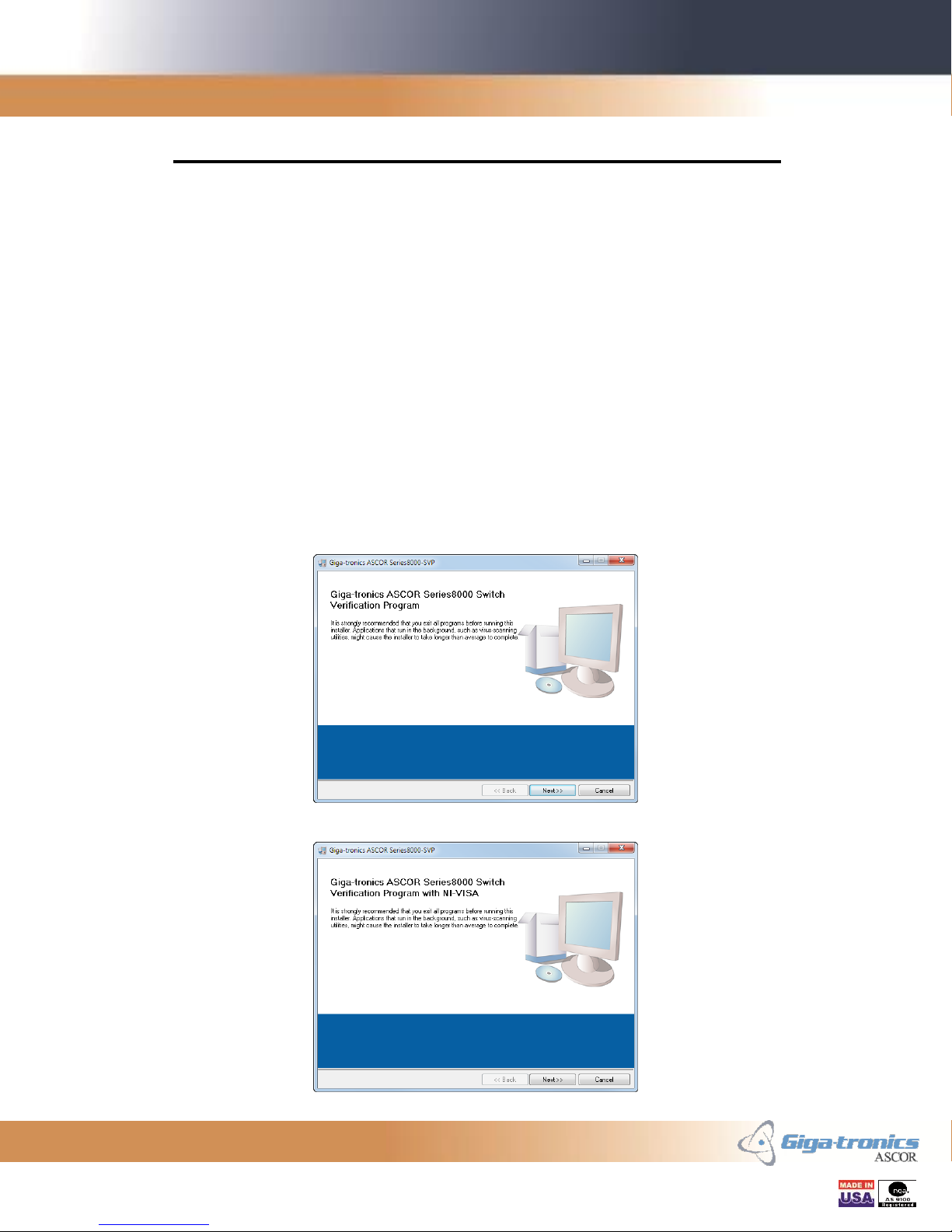
2.1.1 Setup Opening Panel
One of the two Opening Panels for the Installation program will appear. Click Next to
continue.
Getting Started Guide, Part Number 07507593, Rev C, August 14, 2013
Figure 1 - Setup Opening Panel
Figure 2 – Setup with I/O Opening Panel
6 of 38
Page 7
Giga-tronics ASCOR SERIES 8000 Getting Started Guide Rev. C
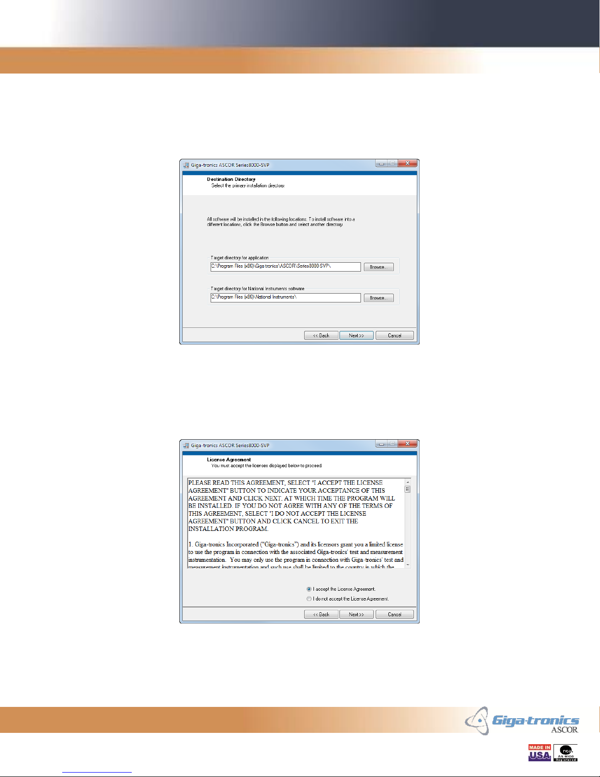
2.1.2 Destination Directory Panel
Set the destination folder if you desire to install the Series8000 GUI or the I/O driver into
a different folder. In normal conditions, there is no need to change these folders. Click
Next to continue.
Figure 3 - Destination Directory Panel
2.1.3 License Agreement Panel
Please read the License Agreement and click on the “I accept the License Agreement”
radio button. Click Next to continue.
Figure 4 - License Agreement Panel
Getting Started Guide, Part Number 07507593, Rev C, August 14, 2013
7 of 38
Page 8
Giga-tronics ASCOR SERIES 8000 Getting Started Guide Rev. C
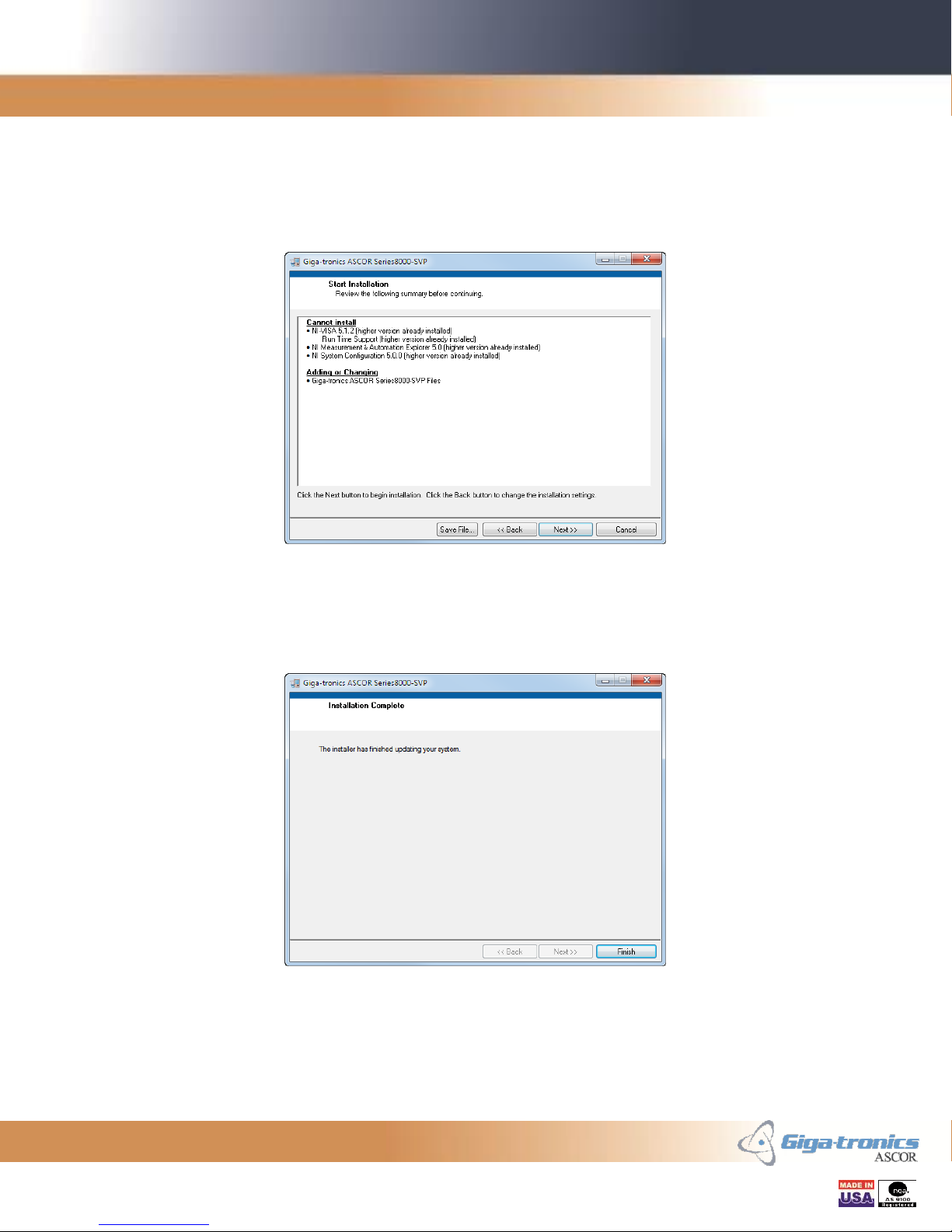
2.1.4 Start Installation Panel
Verify the programs to be installed. Some sections may have already been installed in
prior installations. Click Next to continue.
Figure 5 - Start Installation Panel
2.1.5 Installation Complete Panel
Installation is completed. Click Finish to exit the installation program.
Figure 6 - Installation Complete Panel
Getting Started Guide, Part Number 07507593, Rev C, August 14, 2013
8 of 38
Page 9
Giga-tronics ASCOR SERIES 8000 Getting Started Guide Rev. C
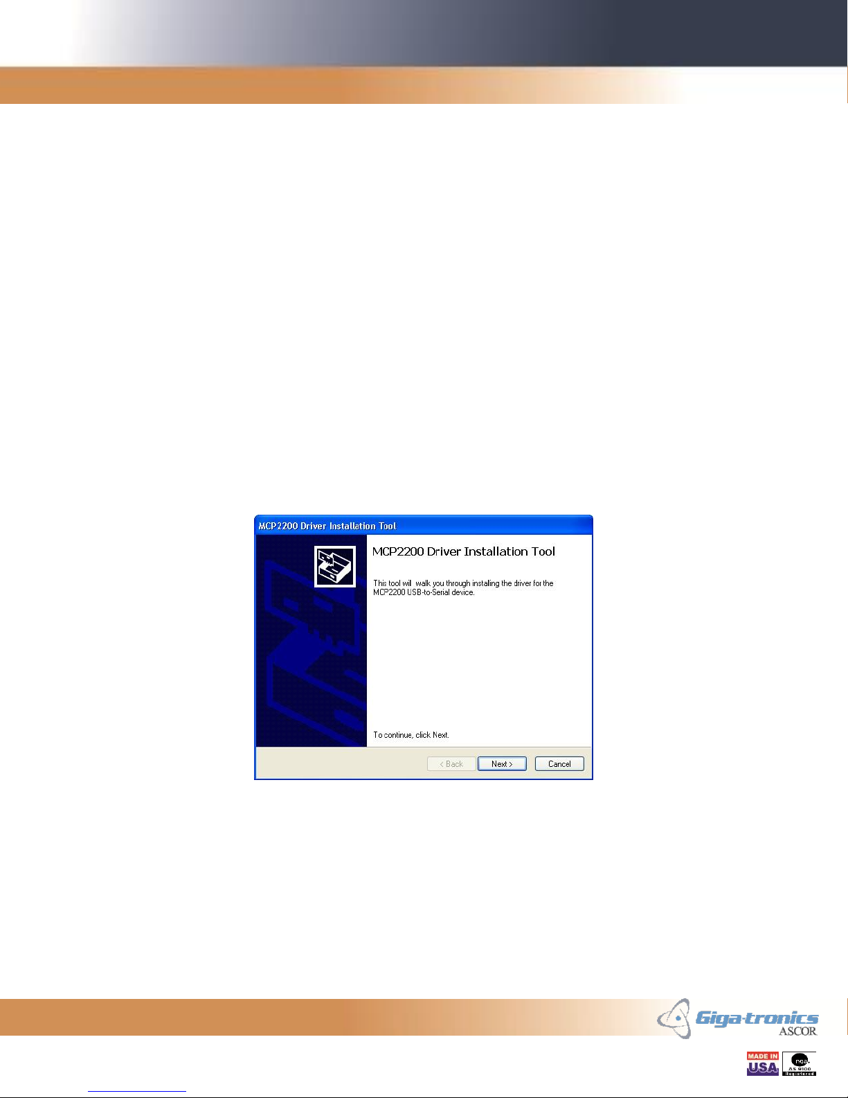
2.2 Installing the USB Device Driver
This section is for installing the USB Device Driver for Windows for USB-based Series
8000 Switch. If your Series 8000 Switch is not a USB-based version then you may skip
this section.
Before plugging in the USB-based Series 8000 Switch to your PC, a device driver for the
USB device must be installed for Windows to recognize the Switch chassis. The
following Windows versions are supported: Windows XP Service Pack 3 or later,
Windows 7 x86, and Windows 7 x64.
There are two versions of the installation program, one for the 32-bit Windows and the
other for the 64-bit Windows. x86 folder holds the installation program for the 32-bit
Windows and x64 folder holds the installation program for the 64-bit Windows. The two
folders are located under MCP2200 Driver Installation Tool folder in the installation
package.
Run the installation program MCP2200DriverInstallationTool.exe from the appropriate
folder and follow the instruction.
Getting Started Guide, Part Number 07507593, Rev C, August 14, 2013
Figure 7 - USB Device Driver Initial Panel
9 of 38
Page 10
Giga-tronics ASCOR SERIES 8000 Getting Started Guide Rev. C
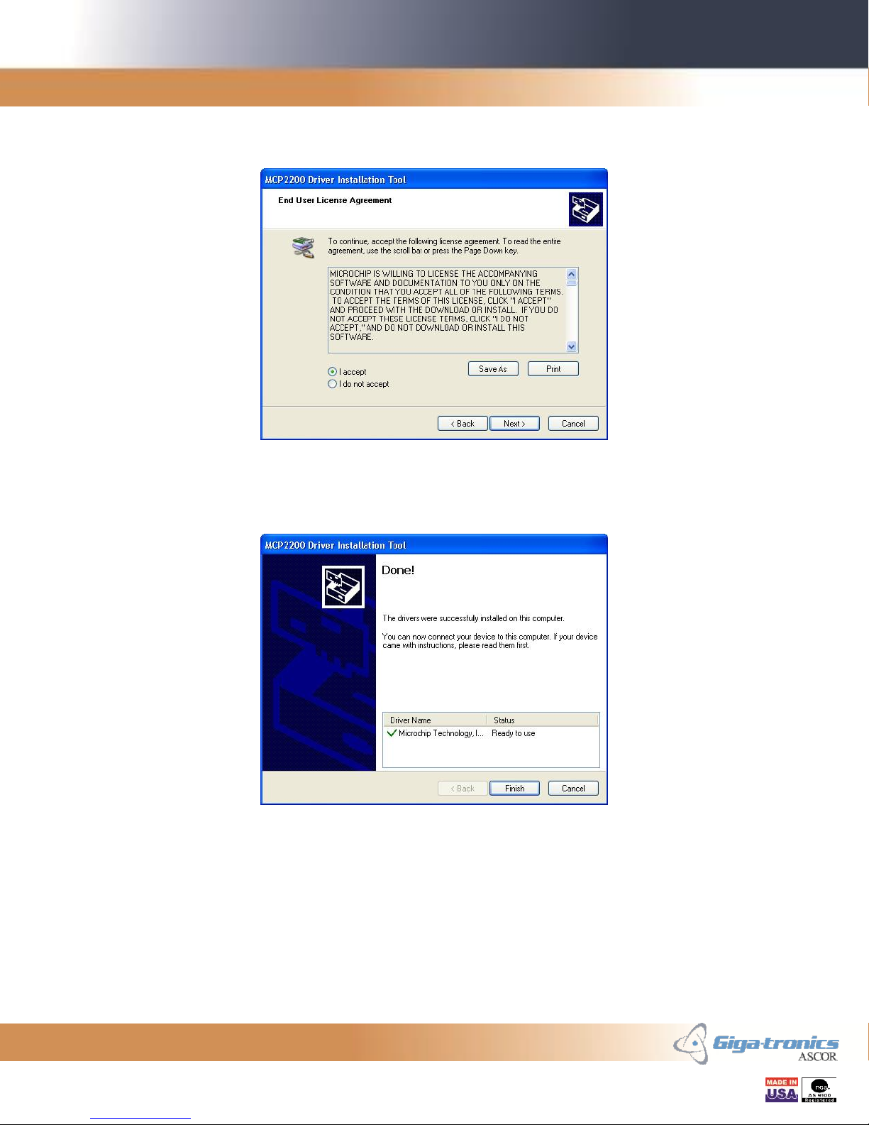
Please read the End User License Agreement and click on the “I accept” radio button.
Click Next to continue.
Figure 8 - USB Device Driver EULA Panel
Installation is completed. Click Finish to exit the installation program.
Figure 9 - USB Device Driver Done Panel
If the Series 8000 Switch was plugged in your PC before the driver was installed,
Windows may assign a wrong driver for the Series 8000 Switch. In such a case, unplug
the USB cable of Series 8000 Switch to the PC, uninstall the incorrect driver, restart
Windows, and install the USB Device Driver.
Getting Started Guide, Part Number 07507593, Rev C, August 14, 2013
10 of 38
Page 11
Giga-tronics ASCOR SERIES 8000 Getting Started Guide Rev. C
3. Starting the Series 8000 GUI Program
After the successful installation of the Series 8000 GUI program, it can be started from
the Start Menu. Please follow one of the link below:
Start >> Series8000-SVP
Or
Start >> All Programs >> Giga-tronics >> ASCOR >> Series8000-SVP >> Series8000-SVP
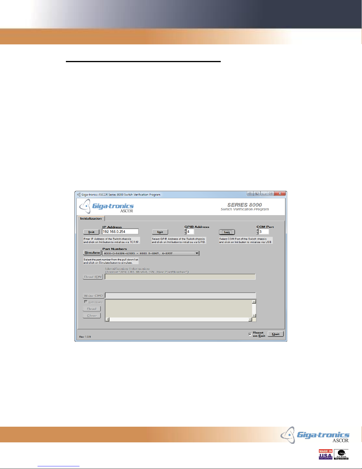
3.1 Main Panel - Initialization Tab
The Series 8000 GUI program starts up in the Initialization Tab of the Main Panel. From
this tab you can connect to the Series 8000 Switch in live mode. Or you can run this
program in simulation mode.
Getting Started Guide, Part Number 07507593, Rev C, August 14, 2013
Figure 10 - Series 8000 SVP Initialization Tab
11 of 38
Page 12
Giga-tronics ASCOR SERIES 8000 Getting Started Guide Rev. C
3.1.1 Live Mode
3.1.1.1 Connecting to the Series 8000 Switch
Series 8000 GUI supports LAN-based and GPIB-based Series 8000 Switch. Follow the
appropriate section below.
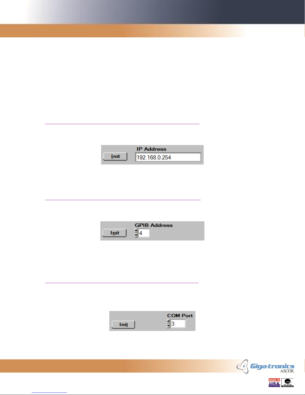
3.1.1.1.1 For LAN-based Series 8000 Switch
If this is the first time connecting to the LAN-based Series 8000 Switch, see Section 4
Connecting to LAN-based Series 8000 Switch for the First Time for more information.
Enter the IP Address of the Series 8000 Switch and click on Init button.
3.1.1.1.2 For GPIB-based Series 8000 Switch
If this is the first time connecting to the GPIB-based Series 8000 Switch, see Section 7
Connecting to GPIB-based Series 8000 Switch for the First Time for more information.
Select the GPIB address of the Series 8000 Switch and click on Init button.
3.1.1.1.3 For USB-based Series 8000 Switch
If this is the first time connecting to the USB-based Series 8000 Switch, see Section 9
Connecting to USB-based Series 8000 Switch for the First Time for more information.
Select the COM port of the PC that is used for the Series 8000 Switch and click on Init
button.
Getting Started Guide, Part Number 07507593, Rev C, August 14, 2013
12 of 38
Page 13

Giga-tronics ASCOR SERIES 8000 Getting Started Guide Rev. C
3.1.1.2 Identification Information
After successful initialization, identification information is queried from the Series 8000
Switch and displayed on the display.
The format of the Identification Information is as follows:
<Manufacturer Name>, <Model>, <SN>, <Rev> <PartNumber>
Manufacturer Name is “ASCOR”.
Model is the model number and it is either “8000” for the unit that does not support
switch access counting capability. Or “8000-001” for the unit that supports switch access
counting capability. These two model numbers are used for all different variations of the
Series 8000 Switch including 8900 family.
SN is the serial number field of “S/N” header and a seven digit serial number of the unit
separated by a space.
Rev is the revision number field of “REV” header and a revision number of the chassis
assembly separated by a space.
PartNumber is the part number field of “P/N” header and a part number of the chassis
separated by a space.
The Identification Information can be queried again by simply clicking the Read IDN
button.
3.1.1.3 Manual Command Entry
Commands to the Series 8000 Switch can be manually from the Manual Command Entry
block.
Enter the command in the entry section on the right and click the Enter key of the
keyboard or click on the Write CMD button to send the command.
Getting Started Guide, Part Number 07507593, Rev C, August 14, 2013
13 of 38
Page 14

Giga-tronics ASCOR SERIES 8000 Getting Started Guide Rev. C
3.1.1.4 Response Display
After a query command a response from the Series 8000 Switch is displayed in the
Response Display.
Enabling the Auto Query function will make the Series 8000 GUI program automatically
read the response after query command. If the Auto Query function is disabled, the
response to the query command can be read back by clicking on the Read button.
Clicking the Clear button clears the content of the Response Display.
3.1.2 Simulation Mode
If you do not have the Series 8000 Switch to connect or if you simply want to run the
Series 8000 GUI program in simulation mode, select the desired part number of the unit
to simulate from the Part Number pull down menu and click the Simulate button.
The controls and displays for the functionalities that are not supported in simulation
mode are dimmed out and cannot be used. Any responses to the query commands are not
simulated and default values are used instead.
Getting Started Guide, Part Number 07507593, Rev C, August 14, 2013
14 of 38
Page 15

Giga-tronics ASCOR SERIES 8000 Getting Started Guide Rev. C
3.2 Main Panel - Switch Control Tab
The Switch Control Tab gives the capability to toggle the switch by simply clicking on
the desired pin. This tab represents the front panel of the connected Series 8000 Switch
that was automatically identified by the GUI program. In simulation mode this tab
represents the front panel of the Series 8000 Switch selected by Part Number pull down
menu in the Initialization tab.
The Series 8000 GUI supports various types of Series 8000 Switch. The panel below
shows the virtual panel for the Model 8902 which can be identified by the part number
90570310 displayed on the sub tab.
Figure 11 - Series 8000 SVP Switch Control Tab
The green or yellow color on the virtual LED signifies the associated pins are connected
together. The black pins signify that there are no connections between the pins.
Figure 12 - SP6T Switch Block Figure 13 - SPDT Switch Block
Getting Started Guide, Part Number 07507593, Rev C, August 14, 2013
Figure 14 - Transfer Switch
Block
15 of 38
Page 16

Giga-tronics ASCOR SERIES 8000 Getting Started Guide Rev. C
3.2.1 Closing and Opening Switches using Virtual LEDs
The switch can be controlled by clicking on the virtual LEDs.
For SP3T, SP4T, SP5T, SP6T, and SP8T switches, click on the unlit (black) virtual LED
corresponding to the physical switch pin to connect a path from the corresponding pin to
the common pin. Two virtual LEDs will light up indicating the corresponding path is
closed. Click on either of the lit (green) virtual LEDs to open the connected path.
For SPDT switches, click on the virtual LED for the Normally Open (NO) to connect the
path from Common to Normally Open. This is an energized or on state. Click on the
virtual LED for the Normally Closed (NC) to connect from Common to Normally
Closed. This is a de-energized or off state. Alternatively, click on the virtual LED for
Common (C) to toggle between Normally Open and Normally Closed states.
For Transfer switches, click on the top right virtual LED to connect the path from
Common to Normally Open. This is an energized or on state. In this state the paths
along the horizontal pins are connected. Click on the bottom left virtual LED to connect
the path from Common to Normally Closed. This is a de-energized or off state. In this
state the paths along the vertical pins are connected. Alternatively, click on the top left or
bottom right virtual LEDs to toggle between Normally Open and Normally Closed states.
3.2.2 Closing and Opening Switches using Numerical Controls
The switch can be controlled by selecting the desired position using the numerical control
associated to the switch.
For SP3T, SP4T, SP5T, SP6T, and SP8T switches, the numerical control can be used for
setting the switch to the desired position. Set to 0 to open the switch. Set to non-zero to
close the switch to the desired position. The maximum position varies depending on the
available poles of the switch.
For SPDT and Transfer switches, the numerical control can be used for selecting on and
off states. Set to 0 for the off state. In this state the Common pin will connect to the
Normally Closed pin. Set to 1 for the on state. In this state the Common pin will connect
to the Normally Open pin.
3.2.3 Switch Access Count Indicators
For the Series 8000 Switch where counting capability is available, the counting indicator
displays the running access count of the associated switch.
Getting Started Guide, Part Number 07507593, Rev C, August 14, 2013
16 of 38
Page 17

Giga-tronics ASCOR SERIES 8000 Getting Started Guide Rev. C
3.3 Main Panel - Switch Table Tab
The Switch Table Tab lists all the possible switches for the selected chassis. The table
has six columns – Label, Conn, Available, SW, Count, and Serial Number. The “Label”
column shows the label of the switches on the Series 8000 Switch front panel. The
“Conn” column shows the J-numbers of the socket on the driver board where the plugs of
the switch cables connect. The “Available” column shows the availability of the switch.
The “SW” column shows the switch number used in switch commands. The “Count”
column shows the running access count of the switch. This count can be modified to any
desired value. The “Serial Number” column shows the serial number of the switch.
In simulation mode, Counts and Serial Numbers can be changed in the Switch Table but
cannot be saved and gets reverted to their respective default values.
Click on the Read Table button to restore the Switch Table with
the information stored in the Series 8000 Switch flash memory.
Click on the Save Table button to update the Series 8000 Switch
flash memory with the information in the Switch Table.
Getting Started Guide, Part Number 07507593, Rev C, August 14, 2013
Figure 15 - Series 8000 SVP Switch Table Tab
17 of 38
Page 18

Giga-tronics ASCOR SERIES 8000 Getting Started Guide Rev. C
3.4 Communication Panel
The Communication Panel displays the commands sent from the Series 8000 GUI and
responses returned from the Series 8000 Switch.
Figure 16 - Communication Panel
You can select what gets displayed by toggling the radio button corresponding to the type
of communication. Select the Commands radio button to
display the commands sent to the Series 8000 Switch. Select the
Responses radio button to display the responses returned from the Series
8000 Switch.
Click the Clear Log button to clear the items displayed in the Communication Log
display.
In simulation mode, only the outgoing commands are displayed. Not responses are
simulated.
Getting Started Guide, Part Number 07507593, Rev C, August 14, 2013
18 of 38
Page 19

Giga-tronics ASCOR SERIES 8000 Getting Started Guide Rev. C
4. Connecting to LAN-base Series 8000 Switch for the First
Time
4.1 Equipment needed
First your computer must be equipped with the network capability. Second you will need
an RJ-45 network cable. If you are connecting the Series 8000 Switch directly to the
computer, you may need to use a special crossover cable, especially if your computer
does not have an auto-sensing functionality.
4.2 Connecting to the Series 8000 Switch
When you are connecting to the Series 8000 Switch for the first time, care has to be taken
to have the IP address of the computer and the Series 8000 Switch in the same subnet.
The Series 8000 Switch comes with a factory default IP address of 192.168.0.254. Verify
this address with the IP address labeled next the LAN cable plug on the back of the Series
8000 Switch.
Make sure your computer’s IP address belongs to the same subnet and do not have any IP
address conflict with the Series 8000 Switch or any other devices that are connected in
the network. If you need to change the computer’s IP address go to the Section 4.3
Matching Your Computer’s IP Address to the Series 8000 Switch.
Getting Started Guide, Part Number 07507593, Rev C, August 14, 2013
19 of 38
Page 20

Giga-tronics ASCOR SERIES 8000 Getting Started Guide Rev. C
4.3 Matching Your Computer’s IP Address to the Series 8000 Switch
In order to communicate to the Series 8000 Switch via LAN or to change the IP address
of the Series 8000 Switch, your computer’s IP address must be in the same subnet with
the Series 8000 Switch. You can modify your computer’s IP address from the Internet
Protocol Version Properties dialog box in Windows.
Figure 17 - Internet Protocol Version Properties
Click on the “Use the following IP address” radio button and enter the new IP address of
the computer. Your new IP address should match the first three octets of the IP address
Series 8000 Switch, 192.168.0 in this case. The last octet should be something unique,
100, in this case. Enter “255.255.255.0” for the Subnet mask. Click OK until you exit all
the dialog boxes.
Getting Started Guide, Part Number 07507593, Rev C, August 14, 2013
20 of 38
Page 21

Giga-tronics ASCOR SERIES 8000 Getting Started Guide Rev. C
5. Changing the IP Address of the Series 8000 Switch
The IP address of the LAN-based Series 8000 Switch can be changed from the
configuration web page of the Series 8000 Switch using a web browser. This means that
before you can change the IP address of the Series 8000 Switch, you have to first have
your computer’s IP address set to the same subnet of the Series 8000 Switch. If you need
to match your computer’s IP address to the Series 8000 Switch follow the instruction in
the Section 4.3 Matching Your Computer’s IP Address to the Series 8000 Switch.
Using a web browser go to the Welcome Page of the Series 8000 Switch. You can reach
the Welcome Page by typing the IP address of the Series 8000 Switch, such as
“192.168.0.254” in your browser’s address bar and hit return.
5.1 Welcome Web Page
The Welcome Page gives you information about the Series 8000 Switch that is
connected. The information such as Model number, serial number, revision, MAC
address, and IP address are displayed. A link to the Configuration Page is on the bottom
center of the screen.
Click on the “Go to Configuration Page” button to go to the
Configuration Page.
Getting Started Guide, Part Number 07507593, Rev C, August 14, 2013
Figure 18 - Welcome Web Page
21 of 38
Page 22

Giga-tronics ASCOR SERIES 8000 Getting Started Guide Rev. C
5.2 Configuration Web Page
Configuration Page allows you to change the IP Address and the Net Mask to the desired
values.
Figure 19 - Configuration Web Page
Enter the new IP address and set the Net Mask to 255.255.255.0:
Click on Update Flash button.
Wait for the web page to switch to the Confirmation page.
5.3 Other Configuration Web Page Settings:
Following are some other setting available under the Configuration page. These setting
do not have to be changed for changing the IP address but are presented here for
completeness.
Comm Timeout (in seconds): If the Series 8000 Switch senses no client communication
for more than the Comm Timeout setting, then the Series 8000 Switch will close the
socket, release any locks, and reclaim all associated instrument resources. Use of a short
setting of 3-5 minutes is recommended during the debugging stages to recover broken
Getting Started Guide, Part Number 07507593, Rev C, August 14, 2013
22 of 38
Page 23

Giga-tronics ASCOR SERIES 8000 Getting Started Guide Rev. C
links faster. Use a longer setting of 10 minutes or longer for debugged applications. A
value of 0 disables the Comm Timeout. The Comm Timeout range is between 0 and
4294967295 seconds.
IP KeepAlive: Enables the socket layer of the Series 8000 Switch to send the client side
socket layer a short test message once every 120 minutes if no messages have been sent.
If the other socket fails to reply, the Series 8000 Switch will close the socket, release any
locks, and reclaim all associated instrument links. Do not enable Keep Alive if the target
socket does not support Keep Alive messages. The recommended setting is On.
Auto Close Sockets: Enabling this feature causes the Series 8000 Switch to close the
socket and release all resources when the available link count goes to zero. It is not
recommended when there are other operations running since it can cause communication
loss. The default is Off.
5.4 Confirmation Web Page
The new IP address is saved in the Series 8000 Switch flash memory and the unit has to
be rebooted or power cycled. You can click on the “Return to the Configuration Page”
button if you wish to modify further.
Click on Reboot button.
Getting Started Guide, Part Number 07507593, Rev C, August 14, 2013
Figure 20 - Confirmation Web Page
23 of 38
Page 24

Giga-tronics ASCOR SERIES 8000 Getting Started Guide Rev. C
5.5 Rebooting Web Page
Wait for the Series 8000 Switch to reboot.
Figure 21 - Rebooting Web Page
Click on the “Return to the Welcome Page” button only if the new IP address is the same
as the old IP address.
Otherwise, enter the new IP address into your browser’s address bar and hit return to
verify the change. If the new IP address is in a different subnet as your computer, follow
the instructions in the Section 4.3 Matching Your Computer’s IP Address to the Series
8000 Switch.
Type in the new IP address in your browser.
Verify the new IP address.
Getting Started Guide, Part Number 07507593, Rev C, August 14, 2013
24 of 38
Page 25

Giga-tronics ASCOR SERIES 8000 Getting Started Guide Rev. C
6. Restoring Factory Default IP Address
The IP address of the LAN-based Series 8000 Switch can be restored to the factory
default by pressing the reset button while powering up the device. The default IP address
is 192.168.0.254. Make sure there are no other devices on the network with the same
address. Follow the detailed instructions:
A. Turn off the power to the Series 8000 Switch.
B. Open the cover of the Series 8000 Switch.
C. Locate the relay driver board.
D. Locate the controller board underneath the relay driver board.
E. Locate the white IP Address Reset push button.
F. Press and hold the IP Address Reset button while powering up the Series 8000
Switch.
G. Keep holding the IP Address Reset button for 5 seconds after the power is on.
H. Release the IP Address Reset button.
I. Turn off the power and place the cover back.
J. Make sure the network cable is hooked up.
K. Turn on the power to the Series 8000 Switch.
L. Verify the Series 8000 Switch at the factory default IP address.
M. It may take a while for the address to propagate through the network
Getting Started Guide, Part Number 07507593, Rev C, August 14, 2013
25 of 38
Page 26

Giga-tronics ASCOR SERIES 8000 Getting Started Guide Rev. C
7. Connecting to GPIB-base Series 8000 Switch for the First
Time
7.1 Equipment needed
First your computer must be equipped with the GPIB capability. Second you will need a
GPIB cable.
7.2 Connecting to the Series 8000 Switch
The Series 8000 Switch comes with a factory default GPIB address of 4. Identify the
GPIB address from the DIP switch located to the GPIB connector on the back of the
Series 8000 Switch.
Refer to the Section 8 Changing the GPIB Address of the Series 8000 Switch if you wish
to set the GPIB address of the Series 8000 Switch to another address.
Getting Started Guide, Part Number 07507593, Rev C, August 14, 2013
26 of 38
Page 27

Giga-tronics ASCOR SERIES 8000 Getting Started Guide Rev. C
Address
1 2 3 4 5
0
OFF
OFF
OFF
OFF
OFF
1
OFF
OFF
OFF
OFF
ON
2
OFF
OFF
OFF
ON
OFF
3
OFF
OFF
OFF
ON
ON
4
OFF
OFF
ON
OFF
OFF 5 OFF
OFF
ON
OFF
ON
6
OFF
OFF
ON
ON
OFF
7
OFF
OFF
ON
ON
ON
8
OFF
ON
OFF
OFF
OFF
9
OFF
ON
OFF
OFF
ON
10
OFF
ON
OFF
ON
OFF
11
OFF
ON
OFF
ON
ON
12
OFF
ON
ON
OFF
OFF
13
OFF
ON
ON
OFF
ON
14
OFF
ON
ON
ON
OFF
15
OFF
ON
ON
ON
ON
Address
1 2 3 4 5
16
ON
OFF
OFF
OFF
OFF
17
ON
OFF
OFF
OFF
ON
18
ON
OFF
OFF
ON
OFF
19
ON
OFF
OFF
ON
ON
20
ON
OFF
ON
OFF
OFF
21
ON
OFF
ON
OFF
ON
22
ON
OFF
ON
ON
OFF
23
ON
OFF
ON
ON
ON
24
ON
ON
OFF
OFF
OFF
25
ON
ON
OFF
OFF
ON
26
ON
ON
OFF
ON
OFF
27
ON
ON
OFF
ON
ON
28
ON
ON
ON
OFF
OFF
29
ON
ON
ON
OFF
ON
30
ON
ON
ON
ON
OFF
31
ON
ON
ON
ON
ON
8. Changing the GPIB Address of the Series 8000 Switch
The GPIB address of the Series 8000 Switch can be changed by setting the GPIB Address
DIP switch. The GPIB Address DIP switch is located next to the GPIB connector on the
back of the Series 8000 Switch. There are eight rocker switches in the GPIB Address
DIP switch module. The left most five switches are used for the GPIB addressing. Do
not modify the right most three switches. GPIB address range from 0 to 31. Address 0 is
reserved for the controller. Set the DIP switch according to the GPIB address you wish
to set using the table below.
The factory default GPIB address is 4.
Getting Started Guide, Part Number 07507593, Rev C, August 14, 2013
Figure 22 - GPIB Address to DIP Switch
27 of 38
Page 28

Giga-tronics ASCOR SERIES 8000 Getting Started Guide Rev. C
9. Connecting to USB-base Series 8000 Switch for the First
Time
9.1 Equipment needed
First your computer must be equipped with a USB port that is compatible with USB 1.1
or USB 2.0. Second you are running Windows XP Service Pack 3 or later, Windows 7
x86, or Windows 7 x64. Third you will need a USB adapter cable with Type A to Type
B plugs.
9.2 USB Device Driver Installation
If you have not already installed the USB Device Driver for Windows, please follow the
instruction on Section 2.2 Installing the USB Device Driver to install the driver.
9.3 Identifying the COM Port
After the USB Device Driver is installed and the Series 8000 Switch plugged in and
powered on, go to Windows Device Manager and look for USB Serial Port (COMx)
where x is the port number, under Ports (COM & LPT). Windows assigns an unused
COM Port to the newly plugged in USB-based Series 8000 Switch.
Figure 23 - Device Manager Device Tree
9.4 Setting the COM Port parameters
The Series 8000 Switch is set to 115.2 K baud, 8 data bit, and no parity. The USB Driver
for the newly plugged in Series 8000 Switch must be set to match these settings.
Right click on the USB Serial Port (COMx) identified in the previous section. Then select
Properties to bring up the USB Serial Port (COMx) Properties dialog box. Click on the
Port Settings tab. Then match the port settings to the settings described in Section 10.1
Communication Settings found in the next section. Click OK and then close the Device
Manager dialog box.
Getting Started Guide, Part Number 07507593, Rev C, August 14, 2013
28 of 38
Page 29

Giga-tronics ASCOR SERIES 8000 Getting Started Guide Rev. C
10. USB Interface Operation
10.1 Communication Settings
USB-based Series 8000 Switch has the following serial port binding:
Baud rate: 115200
Data bits: 8
Parity: None
Stop bits: 1
Flow control: None
10.2 Command Termination
Each command that is sent to the USB-based Series 8000 Switch must be terminated with
a line feed character (0Ah). The line feed terminating character is optional for GPIB and
LAN-based Series 8000 Switch.
10.3 Communication Prompt
The USB-based Series 8000 Switch sends back a communication prompt after
completion of each operation to signal that it is ready for the next command. This
prompt must be read before the next command can be sent to the USB-based Series 8000
Switch. The prompt consists of two characters, a greater than character “>” and a line
feed character.
For an output command the sequence of operation is
a) send command and
b) read prompt.
For a query command the sequence is
a) send query command,
b) read input message, and
c) read prompt.
Getting Started Guide, Part Number 07507593, Rev C, August 14, 2013
29 of 38
Page 30

Giga-tronics ASCOR SERIES 8000 Getting Started Guide Rev. C
Command
Description
ROUTe:SWITch Sw, P
Sets a switch to a desired position. Sw is the switch
identification number, 1-nn. P is the desired position as a
decimal value. The sub-table below lists available positions
for different types of switches.
For SP3T, SP4T, SP5T, SP6T, and SP8T switches, setting the
position to 0, disconnects a path between common pin and
any connected pin. Setting the position to a non-zero number
connects a path between common pin and the pin of the
selected position.
Sw Type
Positions
SP3T
0=All Open, 1, 2, 3
SP4T
0=All Open, 1, 2, 3, 4
SP5T
0=All Open, 1, 2, 3, 4, 5
SP6T
0=All Open, 1, 2, 3, 4, 5, 6
SP8T
0=All Open, 1, 2, 3, 4, 5, 6, 7, 8
For SPDT switches, setting the position to 0, connects a path
between common pin and Normally Closed pin. Setting the
position to 1 connects a path between common pin and
Normally Open pin.
Sw Type
Positions
SPDT
0=Normally Closed, 1=Normally Open
For Transfer switches, setting the position to 0, connects a
path along the vertical pins. Setting the position to 1
connects a path along the horizontal pins.
Sw Type
Positions
TRAN
0=Normally Closed, Vertical Pins
1=Normally Open, Horizontal Pins
11. Command Set
The following sections list some of the main commands to control and query the switch.
11.1 Switch Control Commands
The SCPI commands required to set switch positions, query the switch info, and to save
counters are listed below:
Getting Started Guide, Part Number 07507593, Rev C, August 14, 2013
30 of 38
Page 31

Giga-tronics ASCOR SERIES 8000 Getting Started Guide Rev. C
Command
Description
ROUTe:SWITch? Sw
Returns the switch number, switch position, current switch
count, and switch identifier string.
Sw is a number from 1-nn to identify the switch. The
response is: Sw, position, count, ID.
ID consists of the following fields: switch part number,
switch serial number, S or T for Non-terminated or
Terminated switch.
Example:
ROUTe:SWITch? 1
Returns: 1, 5, 1002123, 52200310, 2006001, T
ROUTe:SWITch:SAVe
Saves all switch counter values to flash memory. The
command only saves the current counter values.
ROUTe:SWITch:SAVe?
Queries the number of flash saves done via the
ROUTe:SWITch:SAVe command, and auto save intervals.
Getting Started Guide, Part Number 07507593, Rev C, August 14, 2013
31 of 38
Page 32

Giga-tronics ASCOR SERIES 8000 Getting Started Guide Rev. C
Command
Description
ROUTe:CONFigure:
COUNTer Sw, count
Presets the Switch Counter value. Use this command to set
the switch counter when installing a switch in a chassis. Sw
is a number from 1-50 to identify the switch. Count is the
switch count value for presetting the switch counter to a new
value. Count value ranges from 0 to 100,000,000.
Example:
ROUT:CONF:COUNT 7,15340
Sets switch SW7 to 15,340 counts.
ROUTe:CONFigure:
COUNTer? Sw
Queries the Switch Counter value. Use this command to read
the switch counter. Sw is a number from 1-50 to identify the
switch.
Example:
ROUT:CONF:COUNT? 7
Returns: 15340
ROUTe:CONFigure:
ID Sw, string
Writes the user’s Switch ID string to Switch Sw. Sw is a
number from 1-50 to identify the switch. String is limited to
23 characters plus a linefeed character.
ROUTe:CONFigure:
ID? Sw
Reads the current Switch ID string for Switch Sw. Sw is a
number from 1-50 to identify the switch.
ID consists of the following fields: switch part number,
switch serial number, S or T for Non-terminated or
Terminated switch.
Example:
ROUTe:CONF:ID? 7
Returns: 52200310, 2006001, T
11.2 Switch Configure Commands
The SCPI commands required to set and query switch counts and switch identification
are listed below:
Getting Started Guide, Part Number 07507593, Rev C, August 14, 2013
32 of 38
Page 33

Giga-tronics ASCOR SERIES 8000 Getting Started Guide Rev. C
Command
Description
ROUTe:CONFigure:
ENABle <switch list>
Enables or disables a list of factory preconfigured switches.
The switch list is a list of numbers of the poles in the switch,
in the order of the configured switches. A non-zero (1-255)
value enables the switch; a 0 disables the switch. Switches
are configured at the factory.
Disabling the switch removes the switch control command
for the selected switch.
Sw Type
Enable/Disable number
Disable
0
TRAN
22
SPDT
2
SP3T
3
SP4T
4
SP5T
5
SP6T
6
SP8T
8
Example:
The following example is for a switch chassis configured
with four switches: SW1, SW2, SW6, and SW7.
ROUT:CONF:ENAB (@ 6,6,0,6)
Enables all the switches except SW6
ROUT:CONF:ENAB (@ 6,6,6,6)
Enables all 4 switches
11.3 Switch Enabling Commands
The SCPI commands required to set and query switch enable and to query switch
configuration are listed below:
Getting Started Guide, Part Number 07507593, Rev C, August 14, 2013
33 of 38
Page 34

Giga-tronics ASCOR SERIES 8000 Getting Started Guide Rev. C
Command
Description
ROUTe:CONFigure:
ENABle?
Returns a list of currently enabled switches in the chassis as a
comma separated list. The response is ‘-1’ if there are no
configured switches to report.
Example:
For a chassis with four 6-pole switches, all enabled except
the third configured switch:
ROUT:CONF:ENA?
Returns: 6,6,0,6
ROUTe:CONFigure:
SWITch?
Returns a list of the configured switches in the chassis. The
list is comma separated. If no switches are configured, the
response is 0.
Example:
For a chassis with switch SW1 and SW6
ROUT:CONF:SWIT?
Returns: 1,6
For a chassis with switch SW1, SW2, SW3, SW4
ROUT:CONF:SWIT?
Returns: 1,2,3,4
Getting Started Guide, Part Number 07507593, Rev C, August 14, 2013
34 of 38
Page 35

Giga-tronics ASCOR SERIES 8000 Getting Started Guide Rev. C
Command
Description
*ESR?
Returns the <value> of the "Event Status Register" and then clears it. This will
clear the ERR LED. <value> is an integer whose binary equivalent corresponds
to the state (1 or 0) of bits in the register. The bit weights are:
Bit
Weight
Error
7
128
Power On
6
64
Ext Data Ready F/F
5
32
Command Error
4
16
Execution Error
3
8
Flash Data Corrupted
2
4
Query Error
1
2
EDR F/F#2 Set
0
1
Operation Complete
11.4 IEEE-488.2 Commands
This unit responds to the following IEEE-488.2 commands.
Getting Started Guide, Part Number 07507593, Rev C, August 14, 2013
35 of 38
Page 36

Giga-tronics ASCOR SERIES 8000 Getting Started Guide Rev. C
Command
Description
*IDN?
Identification Query. Returns the device identification code as four fields
separated by commas. These fields are: Manufacturer, Model, Serial Number,
and Hardware revision and part number in the following formats
ASCOR, 8000, S/N XXXXXXX, REV X P/N XXXXXXXX
or
ASCOR, 8000-001, S/N XXXXXXX, REV X P/N XXXXXXXX
Manufacturer field is “ASCOR”.
Model Field is either “8000” to denote switch chassis without switch access
counting capability. Or “8000-001” to denote switch chassis with switch access
counting capability. These two model numbers are used for all different
variations of the Series 8000 and Series 8900 switch family.
Serial Number field consists of “S/N” header followed by a seven digit serial
number.
Hardware revision sub field consists of “REV” header followed by a chassis
revision number.
Part Number sub field consists of “P/N” header followed by a part number of the
switch chassis.
Example:
For 90570320 chassis:
*IDN?
Returns: ASCOR, 8000-001, S/N 1234567, REV A P/N 90570320
For 90570310 chassis:
*IDN?
Returns: ASCOR, 8000-001, S/N 1234567, REV A P/N 90570310
Getting Started Guide, Part Number 07507593, Rev C, August 14, 2013
36 of 38
Page 37

Giga-tronics ASCOR SERIES 8000 Getting Started Guide Rev. C
12. Sample Program
The following code is a complete C++ program written using Microsoft Visual Studio
2005. It is a simple program but covers the necessary steps to control the Series 8000
Switch.
This program performs the following:
1. Establishes connection to the default resource manager.
2. Creates a session handle for the Series 8000 Switch.
3. Sends commands to toggle switch 1.
4. Sends commands to query switch 1.
5. Reads response to the query.
6. Closes the session handle.
7. Closes the connection to the default resource manager.
This program uses VISA for the I/O driver. VISA Runtime Library is included with the
installation of the Series 8000 GUI program.
In order to dynamically link with the VISA.dll, Microsoft Visual Studio project property
for the program must be modified to include visa32.lib under Additional Dependencies.
Getting Started Guide, Part Number 07507593, Rev C, August 14, 2013
37 of 38
Page 38

Giga-tronics ASCOR SERIES 8000 Getting Started Guide Rev. C
// series8000.cpp : Sample console program for controlling Series 8000 Switch.
//
#include "stdafx.h"
#include "string.h"
#include "visa.h"
int _tmain(int argc, _TCHAR* argv[])
{
ViChar resourceName[255], cmdBuf[255], rspBuf[255];
ViSession rmSession, instrSession;
ViStatus status;
ViUInt32 retCnt;
// Open Resource Manager Session
status = viOpenDefaultRM (&rmSession);
if (status < VI_SUCCESS) {
return status;
}
// Open Instrument Session for Series 8000 Switch at IP address 192.168.0.254
strcpy_s (resourceName, "TCPIP0::192.168.0.254::inst0::INSTR");
status = viOpen (rmSession, resourceName, VI_NULL, VI_NULL, &instrSession);
if (status != VI_SUCCESS) {
instrSession = 0;
return status;
}
// Send the command to open switch 1
strcpy_s (cmdBuf, "ROUTe:SWITch 1, 0");
status = viWrite (instrSession, (ViBuf)cmdBuf, (ViUInt32) strlen (cmdBuf), &retCnt);
if (status != VI_SUCCESS) {
return status;
}
// Send the command to close switch 1 position 1
strcpy_s (cmdBuf, "ROUTe:SWITch 1, 1");
status = viWrite (instrSession, (ViBuf)cmdBuf, (ViUInt32) strlen (cmdBuf), &retCnt);
if (status != VI_SUCCESS) {
return status;
}
// Send the command to query switch 1 position
strcpy_s (cmdBuf, "ROUTe:SWITch? 1");
status = viWrite (instrSession, (ViBuf)cmdBuf, (ViUInt32) strlen (cmdBuf), &retCnt);
if (status != VI_SUCCESS) {
return status;
}
// Read the response to the query
status = viRead (instrSession, (ViBuf)rspBuf, 100, &retCnt);
if (status != VI_SUCCESS) {
return status;
}
// Close the Instrument Session for the Series 8000 Switch
status = viClose (instrSession);
if (status != VI_SUCCESS) {
return status;
}
// Close the Resource Manager Session
status = viClose (rmSession);
if (status != VI_SUCCESS) {
return status;
}
return 0;
}
Figure 24: C++ Sample Program
Getting Started Guide, Part Number 07507593, Rev C, August 14, 2013
38 of 38
 Loading...