

Page 1
Manual 07500770 Model 3000-46
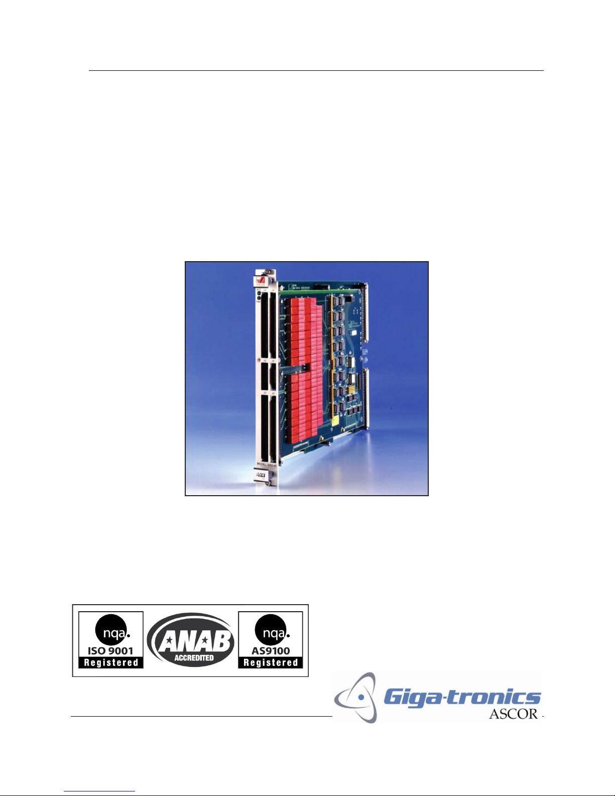
Model 3000-46
64 DPDT & 16(1x8) Multiplexer
90400750
Page 1
Operation Manual
Page 2

Manual 07500770 Model 3000-46
Warranty
Giga-tronics Series 3000 Switching Modules are warranted against
defective materials and workmanship for three years from date of shipment,
or as detailed in the warranty section of this manual. Giga-tronics will, at its
option, repair or replace products that are proven defective during the
warranty period. This warranty DOES NOT cover damage resulting from
improper use, nor workmanship other than Giga-tronics service. There is no
implied warranty of fitness for a particular purpose, nor is Giga-tronics liable
for any consequential damages. Specification and price change privileges are
reserved by Giga-tronics.
All technical data and specifications in this publication are subject to change without prior notice and do
not represent a commitment on the part of Giga-tronics, Incorporated.
© 2011 Giga-tronics Incorporated. All rights reserved. Printed in the U.S.A.
CONTACT INFORMATION
Giga-tronics, Incorporated
4650 Norris Canyon Road
San Ramon, California 94583
Telephone: 800.726.4442 (only within the United States)
925.328.4650
Fax: 925.328.4700
On the Internet: www.gigatronics.com
Page 2
Operation Manual
Page 3

Manual 07500770 Model 3000-46
89/336/EEC and 73/23/EEC
EMC Directive and Low Voltage Directive
EN61010-1 (1993)
Electrical Safety
EN61326-1 (1997)
EMC – Emissions and Immunity
Manufacturer’s Name:
Manufacturer’s Address
Giga-tronics, Incorporated
4650 Norris Canyon Road
San Ramon, California 94583
U.S.A.
Type of Equipment:
Model Series Number
Switching Module
3000-46
Regulatory compliance information
This product complies with the essential requirements of the following applicable European
Directives, and carries the CE mark accordingly.
Declaration of Conformity on file. Contact Giga-tronics at the following;
Giga-tronics, Incorporated
4650 Norris Canyon Road
San Ramon, California 94583
Telephone: 800.726.4442 (only within the United States)
925.328.4650
Fax: 925.328.4700
Page 3
Operation Manual
Page 4

Manual 07500770 Model 3000-46
TPCI
Number
TPCI Issue
Date
Date Entered
Comments
Record of Changes to This Manual
Use the table below to maintain a permanent record of changes to this document. Corrected
replacement pages are issued as Technical Publication Change Instructions (TPCI). When you
are issued a TPCI, do the following:
1. Insert the TPCI at the front of the manual binder.
2. Remove the pages from the manual binder that are noted in the TPCI.
3. Replace the page(s) removed in the previous step with the corrected page(s).
4. Record the changes in the table below.
Page 4
Operation Manual
Page 5

Manual 07500770 Model 3000-46
Revision History
Revision
Description of Change
Chg Order #
Approved By
A
Initial Release
B
Updated
C
Reformatted 3/12
RCW
Page 5
Operation Manual
Page 6

Manual 07500770 Model 3000-46
Contents
Contents ........................................................................................................................................................ 6
Chapter 1 Introduction ................................................................................................................................. 7
1.1 Safety and Manual Conventions ......................................................................................................... 7
1.1.1 Product Reference ....................................................................................................................... 7
1.1.2 Personal Safety Alert ................................................................................................................... 7
1.1.3 Equipment Safety Alert ............................................................................................................... 7
1.1.4 Notes ........................................................................................................................................... 7
1.1.5 Electrical Safety Precautions ....................................................................................................... 7
Chapter 2 Configuration Table ...................................................................................................................... 8
Chapter 3 Functional Description ................................................................................................................. 9
3.1 Introduction ........................................................................................................................................ 9
3.2 General Description ............................................................................................................................ 9
Chapter 4 Block Diagram ............................................................................................................................ 11
Chapter 5 Controls and Indicators .............................................................................................................. 12
5.1 VXI Logical Address ........................................................................................................................... 12
5.2 LEDs................................................................................................................................................... 12
5.2.1 “BUS” LED .................................................................................................................................. 12
5.2.2 “PWR” LED ................................................................................................................................. 12
Chapter 6 Internal Settings ......................................................................................................................... 13
6.1 Fuse ................................................................................................................................................... 13
6.2 VXI
Interrupt Level Selection......................................................................................................... 13
bus
Chapter 7 Specifications ............................................................................................................................. 14
Chapter 9 Register Map .............................................................................................................................. 16
Chapter 10 Connector Configuration .......................................................................................................... 17
Chapter 11 Memory Map ........................................................................................................................... 23
Page 6
Operation Manual
Page 7
Manual 07500770 Model 3000-46
WARNING
CAUTION
Chapter 1 Introduction
1.1 Safety and Manual Conventions
This manual contains conventions regarding safety and equipment usage as described below.
1.1.1 Product Reference
Throughout this manual, the term “Common Core Switching Platform, Series 8800” refers to all models
of within the series, unless otherwise specified.
1.1.2 Personal Safety Alert
WARNING: Indicates a hazardous situation which, if not avoided, could result in
death or serious injury.
1.1.3 Equipment Safety Alert
CAUTION: Indicates a situation which can damage or adversely affect the product or
associated equipment.
1.1.4 Notes
Notes are denoted and used as follows:
NOTE: Highlights or amplifies an essential operating or maintenance procedure, practice, condition or
statement.
1.1.5 Electrical Safety Precautions
Any servicing instructions are for use by service-trained personnel only. To avoid personal injury, do not
perform any service unless you are qualified to do so.
For continued protections against fire hazard, replace the AC line fuse only with a fuse of the same
current rating and type. Do not use repaired fuses or short circuited fuse holders.
Page 7
Operation Manual
Page 8

Manual 07500770 Model 3000-46
Chapter 2 Configuration Table
Module
PL90400750
Assy 90400750
Schematics
MB PL85002160
Assy 85002160
SCH85002160
DB PL85002170
Assy 85002170
SCH85002170
Page 8
Operation Manual
Page 9

Manual 07500770 Model 3000-46
Chapter 3 Functional Description
3.1 Introduction
This User Guide provides a basic description of the Model 3000-46, Flex Switch module. Also included
are installation and input connection procedures, programming information, service and maintenance
information.
3.2 General Description
The Model 3000-46 is a versatile switch array for those who need mix signal capability. The module has
sixty four (64) DPST coaxially shielded relays for dual wire isolation. These relays can be used to switch
signal paths to a digital subsystem. Bandwidth of these paths is greater than 100 MHz. At the input of
these isolation relays are sixteen (16) 8x1 trees which are arranged as eight (8) pairs of 8x1 trees with
individual control of the + and - side of the differential lines in the trees. Additionally, the 8x1 trees can
be combined to form four (4) pairs of 16x1 trees, or two pairs of (2) 32x1 trees, or a single pair of 64x1
tree. All of the combinations of trees allow independent control of the + and - side of the tree for true
differential measurement across any path. This capability allows 64 channels of signals to be switch to
either a digital subsystem or they can be individually switched to analog test equipment. Because all of
these options can be accomplished through software control, this switch module provides maximum
Flexibility regardless of the switch tree selected.
All of the relays are coaxially shielded to provide superior performance. The isolation relays are dual
coaxially shielded reed relays with a common control coil (DPST). These isolation relays provide support
for high speed digital performance, 100 MHz minimum bandwidth (150 MHz typical). The switch trees
are coaxially shielded SPST for maximum analog versatility at >>80 MHz bandwidth. Each of the sixteen
8x1 trees connect to a switch array to allow for combinations as 8x1, 16x1, 32x1, or 64x1 to the output
connectors, J2 and J5. There are sixteen 8x1 outputs, eight 16x1 outputs, four 32x1 outputs, and two
64x1 outputs. They can be all use together or switched out to provide superior performance by isolating
signal paths to improve the transmission line.
With this flexible combination of utilizing the switch trees, up to 30 instruments can be connected to the
Model 3000-46, Flex-switch in addition to the 64 pairs of digital signals. Additionally, two external
references are provided as well as analog and chassis ground for measurements of the + or - side of the
inputs to be measured against the 4 references. Two additional reference inputs are provided on the
daughter board (J5) which are assign to the - side of the measurement trees.
In a typical application without the 3000-46, the system designer would be required to use several
modules and wire them together to get mix signal capability. This inter-module wiring carries with it the
inherent loss of bandwidth due to spliced wires and other wiring requirements associated with intermodule wiring. The ASCOR 3000-46 Flex-switch offers the customer the ability to combine all of the
different modules within a single module with exceptional low noise and high bandwidth performance.
The connectors are Robinson Nugent type P50E series ribbon cable connector. This connector accepts
dual ribbon cables with 0.050" centers. This series of connector has a high density 0.050" pitch contacts
which accepts standard 0.050" pitch ribbon on each side of the connector. The signal pins are located
Page 9
Operation Manual
Page 10

Manual 07500770 Model 3000-46
on J1, J3, J4, and J6. The Output channel ports are located on J2 and J5. Isolated Pins (digital) 1-16 are
located on J1, even number pins (a ribbon cable). The mixed signal pins, Pins 1-16 are located on J1, odd
number pins (other ribbon cable). This organization allows convenient cabling schemes using standard
ribbon cable. The digital signals are kept on one ribbon cable while the mix signal pin is on another
ribbon cable. Pins 17-32 are organized in the same manner on J3. Pins 33-48 are organized in the same
manner on J4. Pins 49-64 are organized in the same manner on J6. The outputs of the switch trees and
the reference inputs are located on J2 and J5. Refer to connector diagram for exact location of the
signals. Associated with each signal pin is the shield. Optimum performance is achieved if shielded
wiring is used with the 3000-46. The adjacent shield provides a short ground path. If ribbon cable is
used, then the shield pins will provide a ground-signal-ground wiring scheme. The analog ground should
be tied to the associated grounds of the signal source. This avoids ground loops and minimized noise
pickup through the analog ground.
ASCOR Model 3000-46
Features
True Mix Signal Switch.
64 Coaxially Shielded DPST Isolation Relays.
16 8x1 Shielded Trees or 8-8x1 Dual Wire.
8 16x1 Shielded Trees or 4-16x1 Dual Wire.
4 32x1 Shield Trees or 2-32x1 Dual or
2 64x1 Shielded Trees or 1- 64x1 Dual Wire.
Measure to 4 External Inputs, Analog Ground or Earth Ground.
100MHz Bandwidth Through Isolation Paths (Digital Path).
50MHz Bandwidth, worst case Through Switch Tree (in to 50 ohm).
Page 10
Operation Manual
Page 11

Manual 07500770 Model 3000-46
Analog Groundplane
UUT
1H
in
Digital out
UUT1L in
Digital out
UUT8H in
Digital out
UUT8L in
Digital out
Group 1 typical
1x81x81x81x8
1x21x2
1x2
1x81x81x81x8
1x21x2
1x2
1x2
8 Channels
Input
SHLD
8 Channels
Input
SHLD
8 Relays
Shield
Shield
Shield
Shield
Chapter 4 Block Diagram
Page 11
Operation Manual
Page 12

Manual 07500770 Model 3000-46
Chapter 5 Controls and Indicators
The following controls and indicators are provided to select and display the functions of the ASCOR
3000-46 Module’s operating environment.
5.1 VXI Logical Address
The Logical Address Switch is dual circular switches, D1 and D2 which are located at the rear of the
module. The address can be set to any value between 1 and 255 (decimal) or 1 and FF (hexadecimal),
(address 0 is reserved for the resource manager). However, the Module fully supports Dynamic
Configuration as defined in Section F of the VXI specification, address 255 (FF) should be selected only if
the Resource Manager also supports Dynamic Configuration.
5.2 LEDs
The following LEDs are visible at the Module’s front panel to indicate the
status of the module’s operation:
5.2.1 “BUS” LED
This green color LED is normally off and will flash on when the module is addressed by the system.
5.2.2 “PWR” LED
This red color LED is normally on when the Module is Powered up.
Page 12
Operation Manual
Page 13

Manual 07500770 Model 3000-46
Chapter 6 Internal Settings
The following items are inside the module and can be reached by removing the side cover.
6.1 Fuse
The ASCOR VXI 3000-46 uses a 10 Amp fuse in the +5 Volt line and is located on
the Mother Board (MB) assembly.
6.2 VXI
The VXIbus interrupt level is set with three bits in the “3Eh” register.
See the section on “A16 ADDRESS SPACE REGISTER DESCRIPTION”.
The interrupt level is factory set to “no interrupt”.
Interrupt Level Selection
bus
Page 13
Operation Manual
Page 14

Manual 07500770 Model 3000-46
Chapter 7 Specifications
Electrical:
Voltage: 200VDC max.
Current: 1.5A Carry, 0.5 A Switched
Power: 10 Watts
Bandwidth:
Isolation relays (to digital):
>100 MHz: single ended into 50 ohms, 150 MHz typical
>150 MHz: differential across inputs (+/-)
8x1 Tree:
>75 MHz : single ended into 50 ohms
>90 MHz: differential
16x1 Tree:
>60 MHz : single ended into 50 ohms
>90 MHz: differential
32x1 Tree:
>55 MHz : single ended into 50 ohms
>85 MHz: differential
64x1 Tree:
>55 MHz : single ended into 50 ohms
>85 MHz: differential
Characteristic Impedance: 50Ω
Connectors:
PCB: (J1,J4,J3 and J6) Robinson Nugent P50E-100P1-SR1-TG
(J2 and J5) Robinson Nugent P50E-26P1-SR1-TG
Mate: Robinson Nugent, IDC Connector,
P50E series, 100 position, socket P50E-100S-TG
Robinson Nugent, IDC Connector,
P50E series, 26 position, socket P50E-26S-TG
Installation Kit: Installation Kit, 89800360, Available on request
(Optional). Includes a full complement of mating
connectors.
Mechanical:
Thickness: 1.200 inches
Width: 10.317 inches
Page 14
Operation Manual
Page 15

Manual 07500770 Model 3000-46
Length: 13.78 inches
Weight: 4 lbs. 10 oz.
Environmental Specifications
Temperature:
Operating: 0º to 55ºC
Storage: - 40º to 75ºC
Relative Humidity:
Operating: 0 to 90% non-condensing
Storage: 0 to 95% non-condensing
Page 15
Operation Manual
Page 16

Manual 07500770 Model 3000-46
Register
Description
8000
Group 1: 8x1 trees (high/low) to I/O 1-8 (+/-)
8002
Group 2: 8x1 trees (high/low) to I/O 9-16 (+/-)
8004
Isolation pins 1-16 (digital +/-) to I/O 1-16 (+/-)
8006
Group 3: 8x1 trees (high/low) ) to I/O 17-24 (+/-)
8008
Group 4: 8x1 trees (high/low) ) to I/O 25-32 (+/-)
800A
Isolation pins 17-32 (digital +/-) to I/O 17-32 (+/-)
800C
Output Control for Group 1-4 (8x1, 16x1)
800E
Output Control for Group 1-4 (32x1, 64x1, external references)
8020
Group 5: 8x1 trees (high/low) to I/O 33-40 (+/-)
8022
Group 6: 8x1 trees (high/low) to I/O 41-48 (+/-)
8024
Isolation pins 33-48 (digital +/-) to I/O 33-48 (+/-)
8026
Group 7: 8x1 trees (high/low) ) to I/O 49-56 (+/-)
8028
Group 8: 8x1 trees (high/low) ) to I/O 57-64 (+/-)
802A
Isolation pins 49-64 (digital +/-) to I/O 49-64 (+/-)
802C
Output Control for Group 5-8 (8x1, 16x1)
802E
Output Control for Group 5-8 (32x1, 64x1, external references)
Chapter 9 Register Map
The Model 3000-46 is a register based VXI module. Each register is 16 bits. They are organized in the
following manner:
See register maps (on page 16 thru page 23) for description and relay number
Page 16
Operation Manual
Page 17

Manual 07500770 Model 3000-46
DESCRIPTION
PIN
PIN
DESCRIPTION
ANALOG SHIELD
100
99
ANALOG SHIELD
PIN 1 IN +
98
97
PIN 1 OUT +
PIN 1 IN -
96
95
PIN 1 OUT -
ANALOG SHIELD
94
93
ANALOG SHIELD
PIN 2 IN +
92
91
PIN 2 OUT +
PIN 2 IN -
90
89
PIN 2 OUT -
ANALOG SHIELD
88
87
ANALOG SHIELD
PIN 3 IN +
86
85
PIN 3 OUT +
PIN 3 IN -
84
83
PIN 3 OUT -
ANALOG SHIELD
82
81
ANALOG SHIELD
PIN 4 IN +
80
79
PIN 4 OUT +
PIN 4 IN -
78
77
PIN 4 OUT -
ANALOG SHIELD
76
75
ANALOG SHIELD
PIN 5 IN +
74
73
PIN 5 OUT +
PIN 5 IN -
72
71
PIN 5 OUT -
ANALOG SHIELD
70
69
ANALOG SHIELD
PIN 6 IN +
68
67
PIN 6 OUT +
PIN 6 IN -
66
65
PIN 6 OUT -
ANALOG SHIELD
64
63
ANALOG SHIELD
PIN 7 IN +
62
61
PIN 7 OUT +
PIN 7 IN -
60
59
PIN 7 OUT -
ANALOG SHIELD
58
57
ANALOG SHIELD
PIN 8 IN +
56
55
PIN 8 OUT +
PIN 8 IN -
54
53
PIN 8 OUT -
ANALOG SHIELD
52
51
ANALOG SHIELD
PIN 9 IN +
50
49
PIN 9 OUT +
PIN 9 IN -
48
47
PIN 9 OUT -
ANALOG SHIELD
46
45
ANALOG SHIELD
PIN 10 IN +
44
43
PIN 10 OUT +
PIN 10 IN -
42
41
PIN 10 OUT -
ANALOG SHIELD
40
39
ANALOG SHIELD
PIN 11 IN +
38
37
PIN 11 OUT +
PIN 11 IN -
36
35
PIN 11 OUT -
ANALOG SHIELD
34
33
ANALOG SHIELD
PIN 12 IN +
32
31
PIN 12 OUT +
PIN 12 IN -
30
29
PIN 12 OUT -
ANALOG SHIELD
28
27
ANALOG SHIELD
PIN 13 IN +
26
25
PIN 13 OUT +
PIN 13 IN -
24
23
PIN 13 OUT -
ANALOG SHIELD
22
21
ANALOG SHIELD
PIN 14 IN +
20
19
PIN 14 OUT +
PIN 14 IN -
18
17
PIN 14 OUT -
ANALOG SHIELD
16
15
ANALOG SHIELD
PIN 15 IN +
14
13
PIN 15 OUT +
PIN 15 IN -
12
11
PIN 15 OUT -
ANALOG SHIELD
10
9
ANALOG SHIELD
PIN 16 IN +
8
7
PIN 16 OUT +
PIN 16 IN -
6
5
PIN 16 OUT -
ANALOG SHIELD
4
3
ANALOG SHIELD
CHASSIS GND
2
1
CHASSIS GND
Chapter 10 Connector Configuration
J1 CONNECTOR DESCRIPTION
Page 17
Operation Manual
Page 18

Manual 07500770 Model 3000-46
DESCRIPTION
PIN
PIN
DESCRIPTION
ANALOG SHIELD
26
25
ANALOG SHIELD
GP1, 8x1 OUT +
24
23
GP2, 8x1 OUT +
GP1, 8x1 OUT -
22
21
GP2, 8x1 OUT -
ANALOG SHIELD
20
19
ANALOG SHIELD
GP1-2, 16x1 OUT +
18
17
GP3-4, 16x1 OUT +
GP1-2, 16x1 OUT -
16
15
GP3-4, 16x1 OUT -
ANALOG SHIELD
14
13
ANALOG SHIELD
GP3, 8x1 OUT +
12
11
GP4, 8x1 OUT +
GP3, 8x1 OUT -
10
9
GP4, 8x1 OUT -
ANALOG SHIELD
8
7
ANALOG SHIELD
GP1-4, 32x1 OUT +
6
5
EXT REF 1+
GP1-4, 32x1 OUT -
4
3
EXT REF 2+
ANALOG SHIELD
2
1
ANALOG SHIELD
J2 CONNECTOR DESCRIPTION
Page 18
Operation Manual
Page 19

Manual 07500770 Model 3000-46
DESCRIPTION
PIN
PIN
DESCRIPTION
ANALOG SHIELD
100
99
ANALOG SHIELD
PIN 17 IN +
98
97
PIN 17 OUT +
PIN 17 IN -
96
95
PIN 17 OUT -
ANALOG SHIELD
94
93
ANALOG SHIELD
PIN 18 IN +
92
91
PIN 18 OUT +
PIN 18 IN -
90
89
PIN 18 OUT -
ANALOG SHIELD
88
87
ANALOG SHIELD
PIN 19 IN +
86
85
PIN 19 OUT +
PIN 19 IN -
84
83
PIN 19 OUT -
ANALOG SHIELD
82
81
ANALOG SHIELD
PIN 20 IN +
80
79
PIN 20 OUT +
PIN 20 IN -
78
77
PIN 20 OUT -
ANALOG SHIELD
76
75
ANALOG SHIELD
PIN 21 IN +
74
73
PIN 21 OUT +
PIN 21 IN -
72
71
PIN 21 OUT -
ANALOG SHIELD
70
69
ANALOG SHIELD
PIN 22 IN +
68
67
PIN 22 OUT +
PIN 22 IN -
66
65
PIN 22 OUT -
ANALOG SHIELD
64
63
ANALOG SHIELD
PIN 23 IN +
62
61
PIN 23 OUT +
PIN 23 IN -
60
59
PIN 23 OUT -
ANALOG SHIELD
58
57
ANALOG SHIELD
PIN 24 IN +
56
55
PIN 24 OUT +
PIN 24 IN -
54
53
PIN 24 OUT -
ANALOG SHIELD
52
51
ANALOG SHIELD
PIN 25 IN +
50
49
PIN 25 OUT +
PIN 25 IN -
48
47
PIN 25 OUT -
ANALOG SHIELD
46
45
ANALOG SHIELD
PIN 26 IN +
44
43
PIN 26 OUT +
PIN 26 IN -
42
41
PIN 26 OUT -
ANALOG SHIELD
40
39
ANALOG SHIELD
PIN 27 IN +
38
37
PIN 27 OUT +
PIN 27 IN -
36
35
PIN 27 OUT -
ANALOG SHIELD
34
33
ANALOG SHIELD
PIN 28 IN +
32
31
PIN 28 OUT +
PIN 28 IN -
30
29
PIN 28 OUT -
ANALOG SHIELD
28
27
ANALOG SHIELD
PIN 29 IN +
26
25
PIN 29 OUT +
PIN 29 IN -
24
23
PIN 29 OUT -
ANALOG SHIELD
22
21
ANALOG SHIELD
PIN 30 IN +
20
19
PIN 30 OUT +
PIN 30 IN -
18
17
PIN 30 OUT -
ANALOG SHIELD
16
15
ANALOG SHIELD
PIN 31 IN +
14
13
PIN 31 OUT +
PIN 31 IN -
12
11
PIN 31 OUT -
ANALOG SHIELD
10
9
ANALOG SHIELD
PIN 32 IN +
8
7
PIN 32 OUT +
PIN 32 IN -
6
5
PIN 32 OUT -
ANALOG SHIELD
4
3
ANALOG SHIELD
CHASSIS GND
2
1
CHASSIS GND
J3 CONNECTOR DESCRIPTION
Page 19
Operation Manual
Page 20

Manual 07500770 Model 3000-46
DESCRIPTION
PIN
PIN
DESCRIPTION
ANALOG SHIELD
100
99
ANALOG SHIELD
PIN 33 IN +
98
97
PIN 33 OUT +
PIN 33 IN -
96
95
PIN 33 OUT -
ANALOG SHIELD
94
93
ANALOG SHIELD
PIN 34 IN +
92
91
PIN 34 OUT +
PIN 34 IN -
90
89
PIN 34 OUT -
ANALOG SHIELD
88
87
ANALOG SHIELD
PIN 35 IN +
86
85
PIN 35 OUT +
PIN 35 IN -
84
83
PIN 35 OUT -
ANALOG SHIELD
82
81
ANALOG SHIELD
PIN 36 IN +
80
79
PIN 36 OUT +
PIN 36 IN -
78
77
PIN 36 OUT -
ANALOG SHIELD
76
75
ANALOG SHIELD
PIN 37 IN +
74
73
PIN 37 OUT +
PIN 37 IN -
72
71
PIN 37 OUT -
ANALOG SHIELD
70
69
ANALOG SHIELD
PIN 38 IN +
68
67
PIN 38 OUT +
PIN 38 IN -
66
65
PIN 38 OUT -
ANALOG SHIELD
64
63
ANALOG SHIELD
PIN 39 IN +
62
61
PIN 39 OUT +
PIN 39 IN -
60
59
PIN 39 OUT -
ANALOG SHIELD
58
57
ANALOG SHIELD
PIN 40 IN +
56
55
PIN 40 OUT +
PIN 40 IN -
54
53
PIN 40 OUT -
ANALOG SHIELD
52
51
ANALOG SHIELD
PIN 41 IN +
50
49
PIN 41 OUT +
PIN 41 IN -
48
47
PIN 41 OUT -
ANALOG SHIELD
46
45
ANALOG SHIELD
PIN 42 IN +
44
43
PIN 42 OUT +
PIN 42 IN -
42
41
PIN 42 OUT -
ANALOG SHIELD
40
39
ANALOG SHIELD
PIN 43 IN +
38
37
PIN 43 OUT +
PIN 43 IN -
36
35
PIN 43 OUT -
ANALOG SHIELD
34
33
ANALOG SHIELD
PIN 44 IN +
32
31
PIN 44 OUT +
PIN 44 IN -
30
29
PIN 44 OUT -
ANALOG SHIELD
28
27
ANALOG SHIELD
PIN 45 IN +
26
25
PIN 45 OUT +
PIN 45 IN -
24
23
PIN 45 OUT -
ANALOG SHIELD
22
21
ANALOG SHIELD
PIN 46 IN +
20
19
PIN 46 OUT +
PIN 46 IN -
18
17
PIN 46 OUT -
ANALOG SHIELD
16
15
ANALOG SHIELD
PIN 47 IN +
14
13
PIN 47 OUT +
PIN 47 IN -
12
11
PIN 47 OUT -
ANALOG SHIELD
10
9
ANALOG SHIELD
PIN 48 IN +
8
7
PIN 48 OUT +
PIN 48 IN -
6
5
PIN 48 OUT -
ANALOG SHIELD
4
3
ANALOG SHIELD
CHASSIS GND
2
1
CHASSIS GND
J4 CONNECTOR DESCRIPTION
Page 20
Operation Manual
Page 21

Manual 07500770 Model 3000-46
DESCRIPTION
PIN
PIN
DESCRIPTION
ANALOG SHIELD
26
25
ANALOG SHIELD
GP5, 8x1 OUT +
24
23
GP6, 8x1 OUT +
GP5, 8x1 OUT -
22
21
GP6, 8x1 OUT -
ANALOG SHIELD
20
19
ANALOG SHIELD
GP5-6, 16x1 OUT +
18
17
GP7-8, 16x1 OUT +
GP5-6, 16x1 OUT -
16
15
GP7-8, 16x1 OUT -
ANALOG SHIELD
14
13
ANALOG SHIELD
GP7, 8x1 OUT +
12
11
GP8, 8x1 OUT +
GP7, 8x1 OUT -
10
9
GP8, 8x1 OUT -
ANALOG SHIELD
8
7
ANALOG SHIELD
GP5-8, 32x1 OUT +
6
5
EXT REF 3+
GP5-8, 32x1 OUT -
4
3
EXT REF 4+
ANALOG SHIELD
2
1
ANALOG SHIELD
J5 CONNECTOR DESCRIPTION
Page 21
Operation Manual
Page 22

Manual 07500770 Model 3000-46
DESCRIPTION
PIN
PIN
DESCRIPTION
ANALOG SHIELD
100
99
ANALOG SHIELD
PIN 49 IN +
98
97
PIN 49 OUT +
PIN 49 IN -
96
95
PIN 49 OUT -
ANALOG SHIELD
94
93
ANALOG SHIELD
PIN 50 IN +
92
91
PIN 50 OUT +
PIN 50 IN -
90
89
PIN 50 OUT -
ANALOG SHIELD
88
87
ANALOG SHIELD
PIN 51 IN +
86
85
PIN 51 OUT +
PIN 51 IN -
84
83
PIN 51 OUT -
ANALOG SHIELD
82
81
ANALOG SHIELD
PIN 52 IN +
80
79
PIN 52 OUT +
PIN 52 IN -
78
77
PIN 52 OUT -
ANALOG SHIELD
76
75
ANALOG SHIELD
PIN 53 IN +
74
73
PIN 53 OUT +
PIN 53 IN -
72
71
PIN 53 OUT -
ANALOG SHIELD
70
69
ANALOG SHIELD
PIN 54 IN +
68
67
PIN 54 OUT +
PIN 54 IN -
66
65
PIN 54 OUT -
ANALOG SHIELD
64
63
ANALOG SHIELD
PIN 55 IN +
62
61
PIN 55 OUT +
PIN 55 IN -
60
59
PIN 55 OUT -
ANALOG SHIELD
58
57
ANALOG SHIELD
PIN 56 IN +
56
55
PIN 56 OUT +
PIN 56 IN -
54
53
PIN 56 OUT -
ANALOG SHIELD
52
51
ANALOG SHIELD
PIN 57 IN +
50
49
PIN 57 OUT +
PIN 57 IN -
48
47
PIN 57 OUT -
ANALOG SHIELD
46
45
ANALOG SHIELD
PIN 58 IN +
44
43
PIN 58 OUT +
PIN 58 IN -
42
41
PIN 58 OUT -
ANALOG SHIELD
40
39
ANALOG SHIELD
PIN 59 IN +
38
37
PIN 59 OUT +
PIN 59 IN -
36
35
PIN 59 OUT -
ANALOG SHIELD
34
33
ANALOG SHIELD
PIN 60 IN +
32
31
PIN 60 OUT +
PIN 60 IN -
30
29
PIN 60 OUT -
ANALOG SHIELD
28
27
ANALOG SHIELD
PIN 61 IN +
26
25
PIN 61 OUT +
PIN 61 IN -
24
23
PIN 61 OUT -
ANALOG SHIELD
22
21
ANALOG SHIELD
PIN 62 IN +
20
19
PIN 62 OUT +
PIN 62 IN -
18
17
PIN 62 OUT -
ANALOG SHIELD
16
15
ANALOG SHIELD
PIN 63 IN +
14
13
PIN 63 OUT +
PIN 63 IN -
12
11
PIN 63 OUT -
ANALOG SHIELD
10
9
ANALOG SHIELD
PIN 64 IN +
8
7
PIN 64 OUT +
PIN 64 IN -
6
5
PIN 64 OUT -
ANALOG SHIELD
4
3
ANALOG SHIELD
CHASSIS GND
2
1
CHASSIS GND
J6 CONNECTOR DESCRIPTION
Page 22
Operation Manual
Page 23

Manual 07500770 Model 3000-46
Chapter 11 Memory Map
A16 Space
Offset (hex) This offset is added to the A16 Base Address of the module. The A16
Base Address for the Flex Switch is equal to the VXIbus logical address
assigned to the Flex Switch shifted left six times and ORed with
hex C000. These registers reside in the VXI Interface circuitry on the
Motherboard (85002160).
00 VXIbus ID Register
02 Device Type Register
04 VXIbus Status/Control Register
06 Offset Register
3E ASCOR Relay Control Register
A24 Space The A24 Base Address of the 3000-46 can be derived from the value stored
in the Offset Register (06h). To obtain the A24 base address, take the 8
most significant bits of the Offset register and map them to the 8 most
significant bits of the A24 Base Address. All other bits in the A24 Base
Address are set to zeroes.
Page 23
Operation Manual
Page 24

Manual 07500770 Model 3000-46
8000h
Relays K1-16, Pin 1 (Ch. 1-8), Pin 2 ( Ch. 1-8)
8002h
Relays K17-32, Pin 3 (Ch. 1-8), Pin 4 ( Ch. 1-8)
8004h
Relays K33-48, Pin 5 (Ch. 1-8), Pin 6 ( Ch. 1-8)
8006h
Relays K49-64, Pin 7 (Ch. 1-8), Pin 8 ( Ch. 1-8)
8008h
Relays K65-80, Pin 9 (Ch. 1-8), Pin 10 ( Ch. 1-8)
800Ah
Relays K81-96, Pin 11 (Ch. 1-8), Pin 12 ( Ch. 1-8)
800Ch
Relays K97-112, Pin 13 (Ch. 1-8), Pin 14 ( Ch. 1-8)
800Eh
Relays K113-128, Pin 15 (Ch. 1-8), Pin 16 ( Ch. 1-8)
8010h
Relays K129-144, isolation relays, group 1, 2
8020h
Relays K1-16, Pin 17 (Ch. 1-8), Pin 18 ( Ch. 1-8)
8022h
Relays K17-32, Pin 19 (Ch. 1-8), Pin 20 ( Ch. 1-8)
8024h
Relays K33-48, Pin 21 (Ch. 1-8), Pin 22 ( Ch. 1-8)
8026h
Relays K49-64, Pin 23 (Ch. 1-8), Pin 24 ( Ch. 1-8)
8028h
Relays K65-80, Pin 25 (Ch. 1-8), Pin 26 ( Ch. 1-8)
802Ah
Relays K81-96, Pin 27 (Ch. 1-8), Pin 28 ( Ch. 1-8)
802Ch
Relays K97-112, Pin 29 (Ch. 1-8), Pin 30 ( Ch. 1-8)
802Eh
Relays K113-128, Pin 31 (Ch. 1-8), Pin 32 ( Ch. 1-8)
8030h
Relays K129-144, isolation relays, group 3, 4
A subset of the ASCOR 3000-46 Custom Registers are relay registers.
See connector assignments for pin and channels assignments with associated relays.
3000-46 Relay Registers
Page 24
Operation Manual
Page 25

Manual 07500770 Model 3000-46
BIT
FUNCTION
COMMENTS
0
Group 1, Pin 1+
J1-98 , Shield: J1-94, K1
1
Group 1, Pin 1-
J1-96 , Shield: J1-94, K2
2
Group 1, Pin 2+
J1-92 , Shield: J1-88, K3
3
Group 1, Pin 2-
J1-90 , Shield: J1-88, K4
4
Group 1, Pin 3+
J1-86 , Shield: J1-82, K5
5
Group 1, Pin 3-
J1-84 , Shield: J1-82, K6
6
Group 1, Pin 4+
J1-80 , Shield: J1-76, K7
7
Group 1, Pin 4-
J1-78 , Shield: J1-76, K8
8
Group 1, Pin 5+
J1-74 , Shield: J1-70, K9
9
Group 1, Pin 5-
J1-72 , Shield: J1-70, K10
10
Group 1, Pin 6+
J1-68 , Shield: J1-64, K11
11
Group 1, Pin 6-
J1-66 , Shield: J1-64, K12
12
Group 1, Pin 7+
J1-62 , Shield: J1-58, K13
13
Group 1, Pin 7-
J1-60 , Shield: J1-58, K14
14
Group 1, Pin 8+
J1-56 , Shield: J1-52, K15
15
Group 1, Pin 8-
J1-54 , Shield: J1-52, K16
0
Group 2, Pin 9+
J1-50 , Shield: J1-46, K17
1
Group 2, Pin 9-
J1-48 , Shield: J1-46, K18
2
Group 2, Pin 10+
J1-44 , Shield: J1-40, K19
3
Group 2, Pin 10-
J1-42 , Shield: J1-40, K20
4
Group 2, Pin 11+
J1-38 , Shield: J1-34, K21
5
Group 2, Pin 11-
J1-36 , Shield: J1-34, K22
6
Group 2, Pin 12+
J1-32 , Shield: J1-28, K23
7
Group 2, Pin 12-
J1-30 , Shield: J1-28, K24
8
Group 2, Pin 13+
J1-26 , Shield: J1-22, K25
9
Group 2, Pin 13-
J1-24 , Shield: J1-22, K26
10
Group 2, Pin 14+
J1-20 , Shield: J1-16, K27
11
Group 2, Pin 14-
J1-18 , Shield: J1-16, K28
12
Group 2, Pin 15+
J1-14 , Shield: J1-10, K29
13
Group 2, Pin 15-
J1-12 , Shield: J1-10, K30
14
Group 2, Pin 16+
J1-8 , Shield: J1-4, K31
15
Group 2, Pin 16-
J1-6 , Shield: J1-4, K32
Model 3000-46 Motherboard SCH85002160
Register 8000h (mother board)
Function: Group 1 8X1
Register 8002h (mother board)
Function: Group 2 8X1
BIT, FUNCTION, COMMENTS
Page 25
Operation Manual
Page 26

Manual 07500770 Model 3000-46
BIT
FUNCTION
COMMENTS
0
ISO, Pin 1
J1-98, 96, Shield: J1-94, K33
1
ISO, Pin 2
J1-92, 90, Shield: J1-88, K34
2
ISO, Pin 3
J1-86, 84, Shield: J1-82, K35
3
ISO, Pin 4
J1-80, 78, Shield: J1-86, K36
4
ISO, Pin 5
J1-74, 72, Shield: J1-70, K37
5
ISO, Pin 6
J1-68, 66, Shield: J1-64, K38
6
ISO, Pin 7
J1-62, 60, Shield: J1-58, K39
7
ISO, Pin 8
J1-56, 54, Shield: J1-52, K40
8
ISO, Pin 9
J1-50, 48, Shield: J1-46, K41
9
ISO, Pin 10
J1-44, 42, Shield: J1-40, K42
10
ISO, Pin 11
J1-38, 36, Shield: J1-34, K43
11
ISO, Pin 12
J1-32, 30, Shield: J1-28, K44
12
ISO, Pin 13
J1-26, 24, Shield: J1-22, K45
13
ISO, Pin 14
J1-20, 18, Shield: J1-16, K46
14
ISO, Pin 15
J1-14, 12, Shield: J1-10, K47
15
ISO, Pin 16
J1-8, 6, Shield: J1-4, K48
BIT
FUNCTION
COMMENTS
0
Group 3, Pin 17+
J3-98 , Shield: J3-94, K49
1
Group 3, Pin 17-
J3-96 , Shield: J3-94, K50
2
Group 3, Pin 18+
J3-92 , Shield: J3-88, K51
3
Group 3, Pin 18-
J3-90 , Shield: J3-88, K52
4
Group 3, Pin 19+
J3-86 , Shield: J3-82, K53
5
Group 3, Pin 19-
J3-84 , Shield: J3-82, K54
6
Group 3, Pin 20+
J3-80 , Shield: J3-76, K55
7
Group 3, Pin 20-
J3-78 , Shield: J3-76, K56
8
Group 3, Pin 21+
J3-74 , Shield: J3-70, K57
9
Group 3, Pin 21-
J3-72 , Shield: J3-70, K58
10
Group 3, Pin 22+
J3-68 , Shield: J3-64, K59
11
Group 3, Pin 22-
J3-66 , Shield: J3-64, K60
12
Group 3, Pin 23+
J3-62 , Shield: J3-58, K61
13
Group 3, Pin 23-
J3-60 , Shield: J3-58, K62
14
Group 3, Pin 24+
J3-56 , Shield: J3-52, K63
15
Group 3, Pin 24-
J3-54 , Shield: J3-52, K64
Model 3000-46 Motherboard SCH85002160
Register 8004h (mother board)
Function: ISO RELAYS PINS 1-16
Register 8006h (mother board)
Function: Group 3 8X1
Page 26
Operation Manual
Page 27

Manual 07500770 Model 3000-46
BIT
FUNCTION
COMMENTS
0
Group 4, Pin 25+
J3-50, Shield: J3-46, K65
1
Group 4, Pin 25-
J3-48, Shield: J3-46, K66
2
Group 4, Pin 26+
J3-44, Shield: J3-40, K67
3
Group 4, Pin 26-
J3-42, Shield: J3-40, K68
4
Group 4, Pin 27+
J3-38, Shield: J3-34, K69
5
Group 4, Pin 27-
J3-36, Shield: J3-34, K70
6
Group 4, Pin 28+
J3-32, Shield: J3-28, K71
7
Group 4, Pin 28-
J3-30, Shield: J3-28, K72
8
Group 4, Pin 29+
J3-26, Shield: J3-22, K73
9
Group 4, Pin 29-
J3-24, Shield: J3-22, K74
10
Group 4, Pin 30+
J3-20, Shield: J3-16, K75
11
Group 4, Pin 30-
J3-18, Shield: J3-16, K76
12
Group 4, Pin 31+
J3-14, Shield: J3-10, K77
13
Group 4, Pin 31-
J3-12, Shield: J3-10, K78
14
Group 4, Pin 32+
J3-8, Shield: J3-4, K79
15
Group 4, Pin 32-
J3-6, Shield: J3-4, K80
BIT
FUNCTION
COMMENTS
0
ISO, Pin 17
J3-98, 96, Shield: J3-94, K81
1
ISO, Pin 18
J3-92, 90, Shield: J3-88, K82
2
ISO, Pin 19
J3-86, 84, Shield: J3-82, K83
3
ISO, Pin 20
J3-80, 78, Shield: J3-86, K84
4
ISO, Pin 21
J3-74, 72 , Shield: J3-70, K85
5
ISO, Pin 22
J3-68, 66, Shield: J3-64, K86
6
ISO, Pin 23
J3-62, 60, Shield: J3-58, K87
7
ISO, Pin 24
J3-56, 54, Shield: J3-52, K88
8
ISO, Pin 25
J3-50, 48, Shield: J3-46, K89
9
ISO, Pin 26
J3-44, 42, Shield: J3-40, K90
10
ISO, Pin 27
J3-38, 36, Shield: J3-34, K91
11
ISO, Pin 28
J3-32, 30, Shield: J3-28, K92
12
ISO, Pin 29
J3-26, 24, Shield: J3-22, K93
13
ISO, Pin 30
J3-20, 18, Shield: J3-16, K94
14
ISO, Pin 31
J3-14, 12, Shield: J3-10, K95
15
ISO, Pin 32
J3-8, 6, Shield: J3-4, K96
Model 3000-46 Motherboard SCH85002160
Register 8008 (mother board)
Function: Group 4 8X1
Register 800Ah (mother board)
Function: ISO RELAYS PINS 17-32
Page 27
Operation Manual
Page 28

Manual 07500770 Model 3000-46
BIT
FUNCTION
COMMENTS
0
GP1, 1X8 +
J2-24 , Shield: J2-26, K97
1
GP1, 1X8 -
J2-22, Shield: J2-20, K98
2
GP1, 1X16 +
J2-18, Shield: J2-14, K99
3
GP1, 1X16 -
J2-16, Shield: J2-14, K100
4
GP2, 1X16 +
J2-18, Shield: J2-14, K101
5
GP2, 1X16 -
J2-16, Shield: J2-14, K102
6
GP2, 1X8 +
J2-23, Shield: J2-25, K103
7
GP2, 1X8 -
J2-21, Shield: J2-19, K104
8
GP3, 1X8 +
J2-12, Shield: J2-8, K105
9
GP3, 1X8 -
J2-10, Shield: J2-8, K106
10
GP3, 1X16 +
J2-17, Shield: J2-13, K107
11
GP3, 1X16 -
J2-15, Shield: J2-13, K108
12
GP4, 1X16 +
J2-17, Shield: J2-13, K109
13
GP4, 1X16 -
J2-15, Shield: J2-13, K110
14
GP4, 1X8 +
J2-11, Shield: J2-7, K111
15
GP4, 1X8 -
J2-9, Shield: J2-7, K112
BIT
FUNCTION
COMMENTS
0
GP1, 1X32 +
J2-6, Shield: J2-2, K113
1
GP1, 1X32 -
J2-4, Shield: J2-2, K114
2
GP2, 1X32 +
J2-6, Shield: J2-2, K115
3
GP2, 1X32 -
J2-4, Shield: J2-2, K116
4
GP3, 1X32 +
J2-6, Shield: J2-2, K117
5
GP3, 1X32 -
J2-4, Shield: J2-2, K118
6
GP4, 1X32 +
J2-6, Shield: J2-2, K119
7
GP4, 1X32 -
J2-4, Shield: J2-2, K120
8
EXT REF 1 +
J2-5 to J2-6, Shield: J2-1, K121
9
EXT REF 2 +
J2-3 to J2-6, Shield: J2-1, K122
10
ANALOG GND REF +
- K123
11
CHASSIS GND REF +
- K124
12
ISO, 1X32/64 +
J2-6, Shield: J2-2, K125
13
ISO, 1X32/64 -
J2-4 , Shield: J2-2, K126
14
ISO, 1X64 +
J2-6, Shield: J2-2, K127
15
ISO, 1X64 -
J2-4, Shield: J2-2, K128
Model 3000-46 Motherboard SCH85002160
Register 800Ch (mother board)
Function: OUTPUT CONTROL RELAYS
Register 800Eh (mother board)
Function: OUTPUT CONTROL RELAYS
Note: K125/126 are use to isolate pins J2-6/4 to allow signal routing from the mother board or from the
daughter board. J2-6 and J2-4 can be used as a 1x32 or as a 1x64. K127/128 are use to switch in the
1x32 output from the daughter board for a 1x64 capability.
Page 28
Operation Manual
Page 29

Manual 07500770 Model 3000-46
BIT
FUNCTION
COMMENTS
0
Group 5, Pin 33+
J4-98, Shield: J4-94, K1
1
Group 5, Pin 33-
J4-96, Shield: J4-94, K2
2
Group 5, Pin 34+
J4-92, Shield: J4-88, K3
3
Group 5, Pin 34-
J4-90, Shield: J4-88, K4
4
Group 5, Pin 35+
J4-86, Shield: J4-82, K5
5
Group 5, Pin 35-
J4-84, Shield: J4-82, K6
6
Group 5, Pin 36+
J4-80, Shield: J4-76, K7
7
Group 5, Pin 36-
J4-78, Shield: J4-76, K8
8
Group 5, Pin 37+
J4-74, Shield: J4-70, K9
9
Group 5, Pin 37-
J4-72, Shield: J4-70, K10
10
Group 5, Pin 38+
J4-68, Shield: J4-64, K11
11
Group 5, Pin 38-
J4-66, Shield: J4-64, K12
12
Group 5, Pin 39+
J4-62, Shield: J4-58, K13
13
Group 5, Pin 39-
J4-60, Shield: J4-58, K14
14
Group 5, Pin 40+
J4-56, Shield: J4-52, K15
15
Group 5, Pin 40-
J4-54, Shield: J4-52, K16
BIT
FUNCTION
COMMENTS
0
Group 6, Pin 41+
J4-50, Shield: J4-46, K17
1
Group 6, Pin 41-
J4-48, Shield: J4-46, K18
2
Group 6, Pin 42+
J4-44, Shield: J4-40, K19
3
Group 6, Pin 42-
J4-42, Shield: J4-40, K20
4
Group 6, Pin 43+
J4-38, Shield: J4-34, K21
5
Group 6, Pin 43-
J4-36, Shield: J4-34, K22
6
Group 6, Pin 44+
J4-32, Shield: J4-28, K23
7
Group 6, Pin 44-
J4-30, Shield: J4-28, K24
8
Group 6, Pin 45+
J4-26, Shield: J4-22, K25
9
Group 6, Pin 45-
J4-24, Shield: J4-22, K26
10
Group 6, Pin 46+
J4-20, Shield: J4-16, K27
11
Group 6, Pin 46-
J4-18, Shield: J4-16, K28
12
Group 6, Pin 47+
J4-14, Shield: J4-10, K29
13
Group 6, Pin 47-
J4-12, Shield: J4-10, K30
14
Group 6, Pin 48+
J4-8, Shield: J4-4, K31
15
Group 6, Pin 48-
J4-6, Shield: J4-4, K32
Model 3000-46 Daughterboard SCH85002170
Register 8020h (daughter board)
Function: Group 1 8X1
Register 8022h (daughter board)
Function: Group 6 8X1
Page 29
Operation Manual
Page 30

Manual 07500770 Model 3000-46
BIT
FUNCTION
COMMENTS
0
ISO, Pin 33
J4-98, 96 , Shield: J4-94, K33
1
ISO, Pin 34
J4-92, 90, Shield: J4-88, K34
2
ISO, Pin 35
J4-86, 84, Shield: J4-82, K35
3
ISO, Pin 36
J4-80, 78, Shield: J4-86, K36
4
ISO, Pin 37
J4-74, 72, Shield: J4-70, K37
5
ISO, Pin 38
J4-68, 66, Shield: J4-64, K38
6
ISO, Pin 39
J4-62, 60, Shield: J4-58, K39
7
ISO, Pin 40
J4-56, 54, Shield: J4-52, K40
8
ISO, Pin 41
J4-50, 48, Shield: J4-46, K41
9
ISO, Pin 42
J4-44, 42, Shield: J4-40, K42
10
ISO, Pin 43
J4-38, 36, Shield: J4-34, K43
11
ISO, Pin 44
J4-32, 30, Shield: J4-28, K44
12
ISO, Pin 45
J4-26, 24, Shield: J4-22, K45
13
ISO, Pin 46
J4-20, 18, Shield: J4-16, K46
14
ISO, Pin 47
J4-14, 12, Shield: J4-10, K47
15
ISO, Pin 48
J4-8, 6 , Shield: J4-4, K48
BIT
FUNCTION
COMMENTS
0
Group 7, Pin 49+
J6-98, Shield: J6-94, K49
1
Group 7, Pin 49-
J6-96, Shield: J6-94, K50
2
Group 7, Pin 50+
J6-92, Shield: J6-88, K51
3
Group 7, Pin 50-
J6-90, Shield: J6-88, K52
4
Group 7, Pin 51+
J6-86, Shield: J6-82, K53
5
Group 7, Pin 51-
J6-84, Shield: J6-82, K54
6
Group 7, Pin 52+
J6-80, Shield: J6-76, K55
7
Group 7, Pin 52-
J6-78, Shield: J6-76, K56
8
Group 7, Pin 53+
J6-74, Shield: J6-70, K57
9
Group 7, Pin 53-
J6-72, Shield: J6-70, K58
10
Group 7, Pin 54+
J6-68, Shield: J6-64, K59
11
Group 7, Pin 54-
J6-66, Shield: J6-64, K60
12
Group 7, Pin 55+
J6-62, Shield: J6-58, K61
13
Group 7, Pin 55-
J6-60, Shield: J6-58, K62
14
Group 7, Pin 56+
J6-56, Shield: J6-52, K63
15
Group 7, Pin 56-
J6-54, Shield: J6-52, K64
Model 3000-46 Daughterboard SCH85002170
Register 8024h (daughter board)
Function: ISO RELAYS PINS 33-48
Register 8026h (daughter board)
Function: Group 7 8X1
Page 30
Operation Manual
Page 31

Manual 07500770 Model 3000-46
BIT
FUNCTION
COMMENTS
0
Group 8, Pin 57+
J6-50, Shield: J6-46, K65
1
Group 8, Pin 57-
J6-48, Shield: J6-46, K66
2
Group 8, Pin 58+
J6-44, Shield: J6-40, K67
3
Group 8, Pin 58-
J6-42, Shield: J6-40, K68
4
Group 8, Pin 59+
J6-38, Shield: J6-34, K69
5
Group 8, Pin 59-
J6-36, Shield: J6-34, K70
6
Group 8, Pin 60+
J6-32, Shield: J6-28, K71
7
Group 8, Pin 60-
J6-30, Shield: J6-28, K72
8
Group 8, Pin 61+
J6-26, Shield: J6-22, K73
9
Group 8, Pin 61-
J6-24, Shield: J6-22, K74
10
Group 8, Pin 62+
J6-20, Shield: J6-16, K75
11
Group 8, Pin 62-
J6-18, Shield: J6-16, K76
12
Group 8, Pin 63+
J6-14, Shield: J6-10, K77
13
Group 8, Pin 63-
J6-12, Shield: J6-10, K78
14
Group 8, Pin 64+
J6-8, Shield: J6-4, K79
15
Group 8, Pin 64-
J6-6, Shield: J6-4, K80
BIT
FUNCTION
COMMENTS
0
ISO, Pin 49
J6-98, 96, Shield: J6-94, K81
1
ISO, Pin 50
J6-92, 90, Shield: J6-88, K82
2
ISO, Pin 51
J6-86, 84, Shield: J6-82, K83
3
ISO, Pin 52
J6-80, 78, Shield: J6-86, K84
4
ISO, Pin 53
J6-74, 72, Shield: J6-70, K85
5
ISO, Pin 54
J6-68, 66, Shield: J6-64, K86
6
ISO, Pin 55
J6-62, 60, Shield: J6-58, K87
7
ISO, Pin 56
J6-56, 54, Shield: J6-52, K88
8
ISO, Pin 57
J6-50, 48, Shield: J6-46, K89
9
ISO, Pin 58
J6-44, 42, Shield: J6-40, K90
10
ISO, Pin 59
J6-38, 36, Shield: J6-34, K91
11
ISO, Pin 60
J6-32, 30, Shield: J6-28, K92
12
ISO, Pin 61
J6-26, 24, Shield: J6-22, K93
13
ISO, Pin 62
J6-20, 18, Shield: J6-16, K94
14
ISO, Pin 63
J6-14, 12, Shield: J6-10, K95
15
ISO, Pin 64
J6-8, 6, Shield: J6-4, K96
Model 3000-46 Daughterboard SCH85002170
Register 8028 (daughter board)
Function: Group 8 8X1
Register 802Ah (daughter board)
Function: ISO RELAYS PINS 49-64
Page 31
Operation Manual
Page 32

Manual 07500770 Model 3000-46
BIT
FUNCTION
COMMENTS
0
GP5, 1X8 +
J5-24, Shield: J5-26, K97
1
GP5, 1X8 -
J5-22, Shield: J5-20, K98
2
GP5, 1X16 +
J5-18, Shield: J5-14, K99
3
GP5, 1X16 -
J5-16, Shield: J5-14, K100
4
GP6, 1X16 +
J5-18, Shield: J5-14, K101
5
GP6, 1X16 -
J5-16, Shield: J5-14, K102
6
GP6, 1X8 +
J5-23, Shield: J5-25, K103
7
GP6, 1X8 -
J5-21, Shield: J5-19, K104
8
GP7, 1X8 +
J5-12, Shield: J5-8, K105
9
GP7, 1X8 -
J5-10, Shield: J5-8, K106
10
GP7, 1X16 +
J5-17, Shield: J5-13, K107
11
GP7, 1X16 -
J5-15, Shield: J5-13, K108
12
GP8, 1X16 +
J5-17, Shield: J5-13, K109
13
GP8, 1X16 -
J5-15, Shield: J5-13, K110
14
GP8, 1X8 +
J5-11, Shield: J5-7, K111
15
GP8, 1X8 -
J5-9, Shield: J5-7, K112
BIT
FUNCTION
COMMENTS
0
GP5, 1X32 +
J5-6, Shield: J5-2, K113
1
GP5, 1X32 -
J5-4, Shield: J5-2, K114
2
GP6, 1X32 +
J5-6, Shield: J5-2, K115
3
GP6, 1X32 -
J5-4, Shield: J5-2, K116
4
GP7, 1X32 +
J5-6, Shield: J5-2, K117
5
GP7, 1X32 -
J5-4, Shield: J5-2, K118
6
GP8, 1X32 +
J5-6, Shield: J5-2, K119
7
GP8, 1X32 -
J5-4, Shield: J5-2, K120
8
EXT REF 1 +
J5-5 to J5-6, Shield: J5-1, K121
9
EXT REF 2 +
J5-3 to J5-6, Shield: J5-1, K122
10
ANALOG GND REF +
- K123
11
CHASSIS GND REF +
- K124
12
ISO, 1X32/64 +
J5-6, Shield: J5-2, K125
13
ISO, 1X32/64 -
J5-4, Shield: J5-2, K126
14
ISO, 1X64 +
J5-6, Shield: J5-2, K127
15
ISO, 1X64 -
J5-4, Shield: J5-2, K128
Model 3000-46 Daughterboard SCH85002170
Register 802Ch (daughter board)
Function: OUTPUT CONTROL RELAYS
Register 802Eh (daughter board)
Function: OUTPUT CONTROL RELAYS
Note: K125/126 are use to isolate pins J5-6/4 to allow signal routing from the mother board or from the
daughter board. J5-6 and J5-4 can be used as a 1x32 or as a 1x64. K127/128 are use to switch in the
1x32 output from the daughter board for a 1x64 capability.
Page 32
Operation Manual
 Loading...