

Giga-tronics 8502A, 8501A Operation & Maintenance Manual

Manual Par t Number : 20790
Revision Level: C
Configuratio n Code: 27
Print Da te: November 1998
Operation & Maintenance Manual
Series 8500A
Peak Power Meters
. . . . . . . . . . . . . . . . . . . . . . . . . . . . . . . . . . . . . . . . . . . . . . . Certified Product
ISO 9001
Registra: BSI, Certification No. FM 34226, Registered 04 June 1996
Giga-tronics Incorporated ❖ 4650 Norris Canyon Road ❖ San Ramon, California 94583
Telephone (925) 328-4650 or (800) 726-4442 ❖ Telefax (925) 328-4700
Customer Service: Telephone (800) 444-2878 ❖ Telefax (925) 328-4702
. . . . . . . . . . . . . . . . . . . . . . . . . . . . . . . . . . Certified Process
Web Site: www.gigatronics.com

All technical data and specifications is this manual are subject to change without prior notice and
do not represent a commitment on the part of Giga-tronics Incorporated.
©Copyright Giga-tronics Incorporated 1998. All rights reserved.
Printed in U.S.A.
WARRANTY
Giga-tronics Series 8500A instruments are warranted against defective
materials and workmanship for one year from date of shipment.
Giga-tronics will at its option repair or replace products that are proven
defective during the warranty period. This warranty DOES NOT cover
damage resulting from improper use, nor workmanship other than
Giga-tron ics service. There is no implied warranty of fitness for a
particular purpose, nor is Giga-tronics liable for any consequential
damages. S pecification and price change privileges are reserved by
Giga-tronics.
Model Numbers
The Series 8500A includes two mo dels: The single-channel Model 8501A and the dual- channel
Model 8502A. Apart from the number of sensors they sup port, the two models are identical. Both
models are referred to in this manual by the general term 8500A, except where it is necessary to
make a distinction between the models.

Table of Contents
About This Manual . . . . . . . . . . . . . . . . . . . . . . . . . . . . . . . . . . . . . . . . . . . . . . . . . . . . . . . . ix
Convent ions. . . . . . . . . . . . . . . . . . . . . . . . . . . . . . . . . . . . . . . . . . . . . . . . . . . . . . . . . . . . . . xi
Record of Manual Changes . . . . . . . . . . . . . . . . . . . . . . . . . . . . . . . . . . . . . . . . . . . . . . . . . xiii
Special Configurations. . . . . . . . . . . . . . . . . . . . . . . . . . . . . . . . . . . . . . . . . . . . . . . . . . . . . . xv
1 • Introduct ion _______________________________________________________
1.1 Description. . . . . . . . . . . . . . . . . . . . . . . . . . . . . . . . . . . . . . . . . . . . . . . . . . . . . . . . . . . . . . . 1-1
1.1.1 Environmental Requirements . . . . . . . . . . . . . . . . . . . . . . . . . . . . . . . . . . . . . . . . . 1-2
1.1.2 Items Furnished . . . . . . . . . . . . . . . . . . . . . . . . . . . . . . . . . . . . . . . . . . . . . . . . . . . . 1 -2
1.1.3 Items Required. . . . . . . . . . . . . . . . . . . . . . . . . . . . . . . . . . . . . . . . . . . . . . . . . . . . . 1 -2
1.1.4 Tools and Test Equipment . . . . . . . . . . . . . . . . . . . . . . . . . . . . . . . . . . . . . . . . . . . 1-2
1.1.5 Cooling . . . . . . . . . . . . . . . . . . . . . . . . . . . . . . . . . . . . . . . . . . . . . . . . . . . . . . . . . . . 1-2
1.1.6 Cleaning . . . . . . . . . . . . . . . . . . . . . . . . . . . . . . . . . . . . . . . . . . . . . . . . . . . . . . . . . . 1-2
1.1.7 Receiving Inspe c tion . . . . . . . . . . . . . . . . . . . . . . . . . . . . . . . . . . . . . . . . . . . . . . . . 1-2
1.1.8 Returning an Instrument . . . . . . . . . . . . . . . . . . . . . . . . . . . . . . . . . . . . . . . . . . . . . 1-3
1.2 System Specifications . . . . . . . . . . . . . . . . . . . . . . . . . . . . . . . . . . . . . . . . . . . . . . . . . . . . . . 1-4
1.3 Default Settings . . . . . . . . . . . . . . . . . . . . . . . . . . . . . . . . . . . . . . . . . . . . . . . . . . . . . . . . . . . 1-7
2 • O peration _________________________________________________________
2.1 General . . . . . . . . . . . . . . . . . . . . . . . . . . . . . . . . . . . . . . . . . . . . . . . . . . . . . . . . . . . . . . . . . 2-1
2.2 Installation . . . . . . . . . . . . . . . . . . . . . . . . . . . . . . . . . . . . . . . . . . . . . . . . . . . . . . . . . . . . . . . 2-1
2.2.1 PCB-Orient ed Voltage Select or and Fuse Holder . . . . . . . . . . . . . . . . . . . . . . . . . 2 -3
2.2.2 VDE Type Volt age and Fuse Holder. . . . . . . . . . . . . . . . . . . . . . . . . . . . . . . . . . . . 2-4
2.3 Rear Panel Description . . . . . . . . . . . . . . . . . . . . . . . . . . . . . . . . . . . . . . . . . . . . . . . . . . . . . 2-5
2.4 Front Panel Description. . . . . . . . . . . . . . . . . . . . . . . . . . . . . . . . . . . . . . . . . . . . . . . . . . . . . 2-7
2.5 Operation . . . . . . . . . . . . . . . . . . . . . . . . . . . . . . . . . . . . . . . . . . . . . . . . . . . . . . . . . . . . . . . . 2-10
2.5.1 Power On Se lf-Test (POST) . . . . . . . . . . . . . . . . . . . . . . . . . . . . . . . . . . . . . . . . . . 2-10
2.5.2 Warm Up Time and Temperature . . . . . . . . . . . . . . . . . . . . . . . . . . . . . . . . . . . . . . 2-10
2.6 Mode Selection . . . . . . . . . . . . . . . . . . . . . . . . . . . . . . . . . . . . . . . . . . . . . . . . . . . . . . . . . . . 2-11
2.6.1 CW Mode. . . . . . . . . . . . . . . . . . . . . . . . . . . . . . . . . . . . . . . . . . . . . . . . . . . . . . . . . 2-11
2.6.2 Peak Mode. . . . . . . . . . . . . . . . . . . . . . . . . . . . . . . . . . . . . . . . . . . . . . . . . . . . . . . . 2-11
2.6.3 Graph Mode . . . . . . . . . . . . . . . . . . . . . . . . . . . . . . . . . . . . . . . . . . . . . . . . . . . . . . . 2-13
2.7 Self-Cal i bration and Auto-Zeroing. . . . . . . . . . . . . . . . . . . . . . . . . . . . . . . . . . . . . . . . . . . . . 2-14
2.7.1 Self-Cal ibration Procedure. . . . . . . . . . . . . . . . . . . . . . . . . . . . . . . . . . . . . . . . . . . . 2-14
2.7.2 Self-Cal ibration Failures. . . . . . . . . . . . . . . . . . . . . . . . . . . . . . . . . . . . . . . . . . . . . . 2-15
2.7.3 Auto-Zero Function . . . . . . . . . . . . . . . . . . . . . . . . . . . . . . . . . . . . . . . . . . . . . . . . . 2-15
2.8 Measurem e nt Proce d ures. . . . . . . . . . . . . . . . . . . . . . . . . . . . . . . . . . . . . . . . . . . . . . . . . . . 2-16
2.8.1 Frequency Correcti on, Cal Factor, and dB Offset . . . . . . . . . . . . . . . . . . . . . . . . . 2-16
2.8.2 PROM Frequency Correction . . . . . . . . . . . . . . . . . . . . . . . . . . . . . . . . . . . . . . . . . 2-16
2.8.3 User-Supplied Ca l Factor . . . . . . . . . . . . . . . . . . . . . . . . . . . . . . . . . . . . . . . . . . . . 2-17
2.8.4 CW Power Measurement. . . . . . . . . . . . . . . . . . . . . . . . . . . . . . . . . . . . . . . . . . . . . 2-18
2.8.5 Peak Power Measurement . . . . . . . . . . . . . . . . . . . . . . . . . . . . . . . . . . . . . . . . . . . 2-19
2.8.6 Peak Power Measurements Using the Graph Mode . . . . . . . . . . . . . . . . . . . . . . . 2-23
2.8.7 Pulse, Cursor, and M a rker Readouts . . . . . . . . . . . . . . . . . . . . . . . . . . . . . . . . . . . 2-23
2.8.8 Cursor Sub-Mode Functions . . . . . . . . . . . . . . . . . . . . . . . . . . . . . . . . . . . . . . . . . . 2-24
2.8.9 Pulse Parameters Sub-Mode Function s . . . . . . . . . . . . . . . . . . . . . . . . . . . . . . . . . 2-26
Manual No. 20790, Rev C, November 1998
i

Series 8500A Peak Power Meters
2.8.10 Marker Sub-Mode Functions . . . . . . . . . . . . . . . . . . . . . . . . . . . . . . . . . . . . . . . . . . 2-28
2.9 Digital Plotting of Graphic Data. . . . . . . . . . . . . . . . . . . . . . . . . . . . . . . . . . . . . . . . . . . . . . . 2-30
2.9.1 Plotter s Support ed . . . . . . . . . . . . . . . . . . . . . . . . . . . . . . . . . . . . . . . . . . . . . . . . . . 2-30
2.9.2 Procedure for Making Plots . . . . . . . . . . . . . . . . . . . . . . . . . . . . . . . . . . . . . . . . . . . 2-30
2.10 Dual Channel Measurements . . . . . . . . . . . . . . . . . . . . . . . . . . . . . . . . . . . . . . . . . . . . . . . . 2-32
2.10.1 CW, CW Measure ments. . . . . . . . . . . . . . . . . . . . . . . . . . . . . . . . . . . . . . . . . . . . . . 2-32
2.10.2 Peak, Peak Me asurements: Method 1. . . . . . . . . . . . . . . . . . . . . . . . . . . . . . . . . . . 2-32
2.10.3 Peak, Peak Me asurements: Method 2. . . . . . . . . . . . . . . . . . . . . . . . . . . . . . . . . . . 2-33
2.10.4 Peak, CW Meas urements. . . . . . . . . . . . . . . . . . . . . . . . . . . . . . . . . . . . . . . . . . . . . 2-34
2.10.5 Power Ratio Measurements . . . . . . . . . . . . . . . . . . . . . . . . . . . . . . . . . . . . . . . . . . . 2-35
2.11 High Power Measurements . . . . . . . . . . . . . . . . . . . . . . . . . . . . . . . . . . . . . . . . . . . . . . . . . . 2-37
2.11.1 Power Warning - Max/Mi n Power Limits . . . . . . . . . . . . . . . . . . . . . . . . . . . . . . . . . 2-37
2.12 High Power Measurement Procedures . . . . . . . . . . . . . . . . . . . . . . . . . . . . . . . . . . . . . . . . . 2-37
2.12.1 High Power Relative Measurements (8502A only) . . . . . . . . . . . . . . . . . . . . . . . . . 2-39
2.13 Special Capabilities of the PPM . . . . . . . . . . . . . . . . . . . . . . . . . . . . . . . . . . . . . . . . . . . . . . 2-40
2.13.1 Referen ce Delay . . . . . . . . . . . . . . . . . . . . . . . . . . . . . . . . . . . . . . . . . . . . . . . . . . . . 2-40
2.13.2 Single Pulse Measurements. . . . . . . . . . . . . . . . . . . . . . . . . . . . . . . . . . . . . . . . . . . 2-40
2.13.3 Single Pulse Measurement Using Internal Trigger . . . . . . . . . . . . . . . . . . . . . . . . . 2-40
2.13.4 Single Pulse Measurement With an Exter nal Trigg e r . . . . . . . . . . . . . . . . . . . . . . . 2-41
2.14 Swept Peak Power Measurements . . . . . . . . . . . . . . . . . . . . . . . . . . . . . . . . . . . . . . . . . . . . 2-42
2.15 Self-Testing the 8500 A . . . . . . . . . . . . . . . . . . . . . . . . . . . . . . . . . . . . . . . . . . . . . . . . . . . . . 2-44
2.16 Freque ncy Disp lay Disabl e/Enable . . . . . . . . . . . . . . . . . . . . . . . . . . . . . . . . . . . . . . . . . . . . 2-45
2.17 Non-Volatile M emory . . . . . . . . . . . . . . . . . . . . . . . . . . . . . . . . . . . . . . . . . . . . . . . . . . . . . . . 2-45
2.17.1 Memory Features . . . . . . . . . . . . . . . . . . . . . . . . . . . . . . . . . . . . . . . . . . . . . . . . . . . 2-45
2.18 1018B Peak Power Meter Emula tion . . . . . . . . . . . . . . . . . . . . . . . . . . . . . . . . . . . . . . . . . . 2-47
2.18.1 General . . . . . . . . . . . . . . . . . . . . . . . . . . . . . . . . . . . . . . . . . . . . . . . . . . . . . . . . . . . 2-47
2.18.2 Initiating the 1018B Emulation Mode. . . . . . . . . . . . . . . . . . . . . . . . . . . . . . . . . . . . 2-47
3 • Re mote Op eration __________________________________________________
3.1 Introduction. . . . . . . . . . . . . . . . . . . . . . . . . . . . . . . . . . . . . . . . . . . . . . . . . . . . . . . . . . . . . . . 3-1
3.2 Remote Operating Modes . . . . . . . . . . . . . . . . . . . . . . . . . . . . . . . . . . . . . . . . . . . . . . . . . . . 3-2
3.2.1 PPM IEEE Bus Function s. . . . . . . . . . . . . . . . . . . . . . . . . . . . . . . . . . . . . . . . . . . . . 3-2
3.2.2 Front Panel Menus. . . . . . . . . . . . . . . . . . . . . . . . . . . . . . . . . . . . . . . . . . . . . . . . . . 3-3
3.2.3 Power-On Conditi o n . . . . . . . . . . . . . . . . . . . . . . . . . . . . . . . . . . . . . . . . . . . . . . . . . 3-3
3.2.4 Remote and Local Lo ckout Func tions . . . . . . . . . . . . . . . . . . . . . . . . . . . . . . . . . . . 3-4
3.2.5 Output Modes . . . . . . . . . . . . . . . . . . . . . . . . . . . . . . . . . . . . . . . . . . . . . . . . . . . . . . 3-4
3.2.6 Command String Format . . . . . . . . . . . . . . . . . . . . . . . . . . . . . . . . . . . . . . . . . . . . . 3-12
3.2.7 Power Measurement Data Output Format . . . . . . . . . . . . . . . . . . . . . . . . . . . . . . . . 3-12
3.3 GPIB Command Descriptions . . . . . . . . . . . . . . . . . . . . . . . . . . . . . . . . . . . . . . . . . . . . . . . . 3-14
3.3.1 Common Mode Functions . . . . . . . . . . . . . . . . . . . . . . . . . . . . . . . . . . . . . . . . . . . . 3-15
3.3.2 Measureme nt Data Correcti on. . . . . . . . . . . . . . . . . . . . . . . . . . . . . . . . . . . . . . . . . 3-17
3.3.3 Mode Selection and Control . . . . . . . . . . . . . . . . . . . . . . . . . . . . . . . . . . . . . . . . . . . 3-21
3.3.4 Commands for Retrieving Data From the PPM . . . . . . . . . . . . . . . . . . . . . . . . . . . 3-23
3.3.5 Graph Mode GP IB Operation. . . . . . . . . . . . . . . . . . . . . . . . . . . . . . . . . . . . . . . . . . 3-24
3.3.6 Marker Timing Measurements . . . . . . . . . . . . . . . . . . . . . . . . . . . . . . . . . . . . . . . . . 3-26
3.3.7 Manual Marker Placement/Timin g Measurem ent Comma nds . . . . . . . . . . . . . . . . 3-29
3.3.8 Window and Cursor Co ntrol Commands. . . . . . . . . . . . . . . . . . . . . . . . . . . . . . . . . 3-31
3.3.9 Commands to O utput Graphic Dat a to a Con troller . . . . . . . . . . . . . . . . . . . . . . . . 3-33
3.3.10 Plotting Commands . . . . . . . . . . . . . . . . . . . . . . . . . . . . . . . . . . . . . . . . . . . . . . . . . 3-34
3.3.11 Programmi ng Notes . . . . . . . . . . . . . . . . . . . . . . . . . . . . . . . . . . . . . . . . . . . . . . . . . 3-35
3.4 Service Requests and Serial Poll . . . . . . . . . . . . . . . . . . . . . . . . . . . . . . . . . . . . . . . . . . . . . 3-36
3.4.1 Error Condition s . . . . . . . . . . . . . . . . . . . . . . . . . . . . . . . . . . . . . . . . . . . . . . . . . . . . 3-37
3.5 1018B Emulation . . . . . . . . . . . . . . . . . . . . . . . . . . . . . . . . . . . . . . . . . . . . . . . . . . . . . . . . . . 3-38
ii
Manual No. 20790, Rev C, November 1998

Preface
3.6 Status Code Decimal Values . . . . . . . . . . . . . . . . . . . . . . . . . . . . . . . . . . . . . . . . . . . . . . . . 3-41
3.7 Summary of Bus Functions. . . . . . . . . . . . . . . . . . . . . . . . . . . . . . . . . . . . . . . . . . . . . . . . . . 3-43
3.7.1 Normal PPM Operation . . . . . . . . . . . . . . . . . . . . . . . . . . . . . . . . . . . . . . . . . . . . . . 3-43
3.7.2 PPM Stand Alo n e Plot Operation . . . . . . . . . . . . . . . . . . . . . . . . . . . . . . . . . . . . . . 3-43
3.8 GPIB Command Summary . . . . . . . . . . . . . . . . . . . . . . . . . . . . . . . . . . . . . . . . . . . . . . . . . . 3-44
3.9 1018B Emulation Commands . . . . . . . . . . . . . . . . . . . . . . . . . . . . . . . . . . . . . . . . . . . . . . . . 3-52
3.10 Data Formats. . . . . . . . . . . . . . . . . . . . . . . . . . . . . . . . . . . . . . . . . . . . . . . . . . . . . . . . . . . . . 3-52
4 • T heory of O peratio n ________________________________________________
4.1 Introduction . . . . . . . . . . . . . . . . . . . . . . . . . . . . . . . . . . . . . . . . . . . . . . . . . . . . . . . . . . . . . . 4-1
4.2 System Description . . . . . . . . . . . . . . . . . . . . . . . . . . . . . . . . . . . . . . . . . . . . . . . . . . . . . . . . 4-1
4.2.1 Power Supply PC Assembly (A2) . . . . . . . . . . . . . . . . . . . . . . . . . . . . . . . . . . . . . . 4-3
4.2.2 GPIB/CAL Control PC board ( A3). . . . . . . . . . . . . . . . . . . . . . . . . . . . . . . . . . . . . . 4-4
4.2.3 CPU PC Assembly (A4). . . . . . . . . . . . . . . . . . . . . . . . . . . . . . . . . . . . . . . . . . . . . . 4-8
4.2.4 Digital Delay PC Asse mbly (A5) . . . . . . . . . . . . . . . . . . . . . . . . . . . . . . . . . . . . . . . 4-12
4.2.5 Analog PC Ass e mbly (A6/A7) . . . . . . . . . . . . . . . . . . . . . . . . . . . . . . . . . . . . . . . . . 4-20
4.2.6 Front Panel Interface PC Assem bly (A8) . . . . . . . . . . . . . . . . . . . . . . . . . . . . . . . . 4-24
4.2.7 Calibrator PC Assembly (A12) . . . . . . . . . . . . . . . . . . . . . . . . . . . . . . . . . . . . . . . . 4-27
5 • T esting an d Calibr ation _____________________________________________
5.1 General . . . . . . . . . . . . . . . . . . . . . . . . . . . . . . . . . . . . . . . . . . . . . . . . . . . . . . . . . . . . . . . . . 5-1
5.2 Performance Testing. . . . . . . . . . . . . . . . . . . . . . . . . . . . . . . . . . . . . . . . . . . . . . . . . . . . . . . 5-2
5.2.1 Equipment Requi red . . . . . . . . . . . . . . . . . . . . . . . . . . . . . . . . . . . . . . . . . . . . . . . . 5-2
5.2.2 Calibrator Retu rn Loss Test . . . . . . . . . . . . . . . . . . . . . . . . . . . . . . . . . . . . . . . . . . 5-3
5.2.3 Calibrator Output Level Test . . . . . . . . . . . . . . . . . . . . . . . . . . . . . . . . . . . . . . . . . . 5-3
5.2.4 Instrument Plus Power Detector Linearity Test . . . . . . . . . . . . . . . . . . . . . . . . . . . 5-3
5.2.5 Power Linearity Test Setup . . . . . . . . . . . . . . . . . . . . . . . . . . . . . . . . . . . . . . . . . . . 5-4
5.2.6 Delay Accuracy Test . . . . . . . . . . . . . . . . . . . . . . . . . . . . . . . . . . . . . . . . . . . . . . . . 5-6
5.2.7 Analog Output Accuracy Test . . . . . . . . . . . . . . . . . . . . . . . . . . . . . . . . . . . . . . . . . 5-7
5.2.8 Voltage Proportional to Frequency Test . . . . . . . . . . . . . . . . . . . . . . . . . . . . . . . . . 5-7
5.2.9 Detector Return Loss Test . . . . . . . . . . . . . . . . . . . . . . . . . . . . . . . . . . . . . . . . . . . 5-7
5.2.10 Plotter Output/IEEE-488 Interface. . . . . . . . . . . . . . . . . . . . . . . . . . . . . . . . . . . . . . 5-7
5.3 Calibration Procedures . . . . . . . . . . . . . . . . . . . . . . . . . . . . . . . . . . . . . . . . . . . . . . . . . . . . . 5-8
5.3.1 Calibration Equipment Required . . . . . . . . . . . . . . . . . . . . . . . . . . . . . . . . . . . . . . . 5-10
5.3.2 Preset Conditions. . . . . . . . . . . . . . . . . . . . . . . . . . . . . . . . . . . . . . . . . . . . . . . . . . . 5-10
5.3.3 A2 Regulator Board . . . . . . . . . . . . . . . . . . . . . . . . . . . . . . . . . . . . . . . . . . . . . . . . . 5-11
5.3.4 Initial ization. . . . . . . . . . . . . . . . . . . . . . . . . . . . . . . . . . . . . . . . . . . . . . . . . . . . . . . . 5-12
5.3.5 A8 F ront Pane l Interf ace Board . . . . . . . . . . . . . . . . . . . . . . . . . . . . . . . . . . . . . . . 5-12
5.3.6 A6/A7 Analog Board . . . . . . . . . . . . . . . . . . . . . . . . . . . . . . . . . . . . . . . . . . . . . . . . 5-13
5.3.7 A3 GPIB/CAL Control Board. . . . . . . . . . . . . . . . . . . . . . . . . . . . . . . . . . . . . . . . . . 5-15
5.3.8 A4 CPU Board . . . . . . . . . . . . . . . . . . . . . . . . . . . . . . . . . . . . . . . . . . . . . . . . . . . . . 5-15
5.3.9 A5 Digital Delay Bo ard . . . . . . . . . . . . . . . . . . . . . . . . . . . . . . . . . . . . . . . . . . . . . . 5-16
5.3.10 External Interface. . . . . . . . . . . . . . . . . . . . . . . . . . . . . . . . . . . . . . . . . . . . . . . . . . . 5-19
5.3.11 Volume Adjust . . . . . . . . . . . . . . . . . . . . . . . . . . . . . . . . . . . . . . . . . . . . . . . . . . . . . 5-20
Manual No. 20790, Rev C, November 1998
iii

Series 8500A Peak Power Meters
6 • M aintena nce_______________________________________________________
6.1 Introduction. . . . . . . . . . . . . . . . . . . . . . . . . . . . . . . . . . . . . . . . . . . . . . . . . . . . . . . . . . . . . . . 6-1
6.2 Periodic Maintenance. . . . . . . . . . . . . . . . . . . . . . . . . . . . . . . . . . . . . . . . . . . . . . . . . . . . . . . 6-1
6.2.1 Require d Test Equipment. . . . . . . . . . . . . . . . . . . . . . . . . . . . . . . . . . . . . . . . . . . . . 6-2
6.3 Troublesh ooting . . . . . . . . . . . . . . . . . . . . . . . . . . . . . . . . . . . . . . . . . . . . . . . . . . . . . . . . . . . 6-3
6.3.1 Equipment Requi red. . . . . . . . . . . . . . . . . . . . . . . . . . . . . . . . . . . . . . . . . . . . . . . . . 6 - 3
6.3.2 Power-On Failure . . . . . . . . . . . . . . . . . . . . . . . . . . . . . . . . . . . . . . . . . . . . . . . . . . . 6- 3
7 • P arts Lis ts ________________________________________________________
7.1 Introduction. . . . . . . . . . . . . . . . . . . . . . . . . . . . . . . . . . . . . . . . . . . . . . . . . . . . . . . . . . . . . . . 7-1
7.2 Parts Lists for Series 8500A Peak Power Me ters . . . . . . . . . . . . . . . . . . . . . . . . . . . . . . . . 7-1
8501A PEAK PO WER METER . . . . . . . . . . . . . . . . . . . . . . . . . . . . . . . . . . . . . . . . . . . . . . . 7-1
8502A DUAL INPUT PE AK POWER METER. . . . . . . . . . . . . . . . . . . . . . . . . . . . . . . . . . . . 7-2
20512-A 0 0 8501A CHASSIS ASSY . . . . . . . . . . . . . . . . . . . . . . . . . . . . . . . . . . . . . . . . . . . 7-3
20513-A 0 0 8502A CHASSIS ASSY . . . . . . . . . . . . . . . . . . . . . . . . . . . . . . . . . . . . . . . . . . . 7-4
21145 FRONT SUB PANE L ASSY 8501A . . . . . . . . . . . . . . . . . . . . . . . . . . . . . . . . . . . . . . 7-5
21147 FRONT SUB PANE L ASSY 8502A . . . . . . . . . . . . . . . . . . . . . . . . . . . . . . . . . . . . . . 7-5
21146 REAR PANEL ASSY 8501A. . . . . . . . . . . . . . . . . . . . . . . . . . . . . . . . . . . . . . . . . . . . 7-6
21148 REAR PANEL ASSY 8502A. . . . . . . . . . . . . . . . . . . . . . . . . . . . . . . . . . . . . . . . . . . . 7-6
20879 EL DISPLAY MODULE ASSEM BLY . . . . . . . . . . . . . . . . . . . . . . . . . . . . . . . . . . . . . 7-7
20879-A 0 0 EL DISPLAY MODULE SUB ASSY . . . . . . . . . . . . . . . . . . . . . . . . . . . . . . . . . . 7-7
16869 DELAY LINE ASS EMBLY. . . . . . . . . . . . . . . . . . . . . . . . . . . . . . . . . . . . . . . . . . . . . . 7-7
16932-001 INTERCONNECT PCB ASSY. . . . . . . . . . . . . . . . . . . . . . . . . . . . . . . . . . . . . . . 7-8
16932-A 0 1 PCB ASSY PR E-WAVE,INTERCONNE CT . . . . . . . . . . . . . . . . . . . . . . . . . . . . 7-8
16995 PCB ASSY, POWER SUPPLY. . . . . . . . . . . . . . . . . . . . . . . . . . . . . . . . . . . . . . . . . . 7- 10
16995-A 0 0 PCB ASSY PR E-WAVE, PWR SUPPLY . . . . . . . . . . . . . . . . . . . . . . . . . . . . . . 7-10
21014 PCB ASSY GPIB/ CAL CONTROL 8500 . . . . . . . . . . . . . . . . . . . . . . . . . . . . . . . . . . 7-13
21014-A 0 0 PCB ASSY PR E-WAVE,GPIB . . . . . . . . . . . . . . . . . . . . . . . . . . . . . . . . . . . . . . 7-13
16878 PCB ASSY., CPU . . . . . . . . . . . . . . . . . . . . . . . . . . . . . . . . . . . . . . . . . . . . . . . . . . . . 7-16
16878-A 0 0 PCB ASSY PR E-WAVE, CPU . . . . . . . . . . . . . . . . . . . . . . . . . . . . . . . . . . . . . . 7-16
16685 P.C. ASSY, DIGITAL DELAY. . . . . . . . . . . . . . . . . . . . . . . . . . . . . . . . . . . . . . . . . . . 7- 19
16685-A0 0 PCB ASSY PRE-WAVE, DIG. DELAY . . . . . . . . . . . . . . . . . . . . . . . . . . . . . . . . 7-20
20741 ANALOG PCB ASSY . . . . . . . . . . . . . . . . . . . . . . . . . . . . . . . . . . . . . . . . . . . . . . . . . 7-24
20741-A 0 0 PCB ASSY PR E-WAVE, ANALOG. . . . . . . . . . . . . . . . . . . . . . . . . . . . . . . . . . . 7-24
20195 PCB ASSY, FR PNL INTERFACE. . . . . . . . . . . . . . . . . . . . . . . . . . . . . . . . . . . . . . . 7-30
20195-A 0 0 PCB ASSY PR E-WAVE,FRT PNL INT . . . . . . . . . . . . . . . . . . . . . . . . . . . . . . . . 7-30
20526-001 PC BOARD ASSY, FRONT PANEL . . . . . . . . . . . . . . . . . . . . . . . . . . . . . . . . . . 7-33
20055-001 ASSY, 1GHZ CALIBRATOR TYPE N. . . . . . . . . . . . . . . . . . . . . . . . . . . . . . . . . 7-34
20055-A 0 1 CALIBR ATOR SUB ASSY, TYPE N. . . . . . . . . . . . . . . . . . . . . . . . . . . . . . . . . . 7-34
7.3 List of Manufacturers . . . . . . . . . . . . . . . . . . . . . . . . . . . . . . . . . . . . . . . . . . . . . . . . . . . . . . . 7-36
8 • D iagrams __________________________________________________________
8.1 Introduction. . . . . . . . . . . . . . . . . . . . . . . . . . . . . . . . . . . . . . . . . . . . . . . . . . . . . . . . . . . . . . . 8-1
8.2 Applicability. . . . . . . . . . . . . . . . . . . . . . . . . . . . . . . . . . . . . . . . . . . . . . . . . . . . . . . . . . . . . . . 8-1
Model 8501A/8502A Peak Power Meter, DWG# 20522. . . . . . . . . . . . . . . . . . . . . . . . . . . . 8-3
Interconnect P C Assy (A1), DWG# 16932-001. . . . . . . . . . . . . . . . . . . . . . . . . . . . . . . . . . . 8-5
Interconnect Circuit Schematic (A1), DWG# 21088 . . . . . . . . . . . . . . . . . . . . . . . . . . . . . . . 8-6
Power Supply PC Assy (A2), DWG# 16995. . . . . . . . . . . . . . . . . . . . . . . . . . . . . . . . . . . . . 8-9
Power Supply Circuit Schematic (A2), DWG # 16996. . . . . . . . . . . . . . . . . . . . . . . . . . . . . . 8-10
GPIB/Cal Control PC Assy (A3), DWG# 21014 . . . . . . . . . . . . . . . . . . . . . . . . . . . . . . . . . . 8-12
GPIB/Cal Control Circuit Schematic (A3), DWG# 21015 . . . . . . . . . . . . . . . . . . . . . . . . . . . 8-13
CPU PC Assy (A4), DWG# 1 6 878 . . . . . . . . . . . . . . . . . . . . . . . . . . . . . . . . . . . . . . . . . . . . 8-15
iv
Manual No. 20790, Rev C, November 1998

Preface
CPU Circuit Schematic (A4), DWG# 16879 . . . . . . . . . . . . . . . . . . . . . . . . . . . . . . . . . . . . . 8-16
Digital Delay PC Ass y (A5), DWG# 16685 . . . . . . . . . . . . . . . . . . . . . . . . . . . . . . . . . . . . . 8-18
Digital Delay Circuit Schematic (A5), DWG# 16686 . . . . . . . . . . . . . . . . . . . . . . . . . . . . . . 8-19
Analog PC Assy (A6/A7), DWG# 20741 . . . . . . . . . . . . . . . . . . . . . . . . . . . . . . . . . . . . . . . 8-22
Analog Circuit Schematic (A6/A7), DWG# 20742 . . . . . . . . . . . . . . . . . . . . . . . . . . . . . . . . 8-23
Front Panel Interface PC Assy (A8), DWG# 20195. . . . . . . . . . . . . . . . . . . . . . . . . . . . . . . 8-26
Front Panel Interface Circuit Schematic (A8), DWG# 20196 . . . . . . . . . . . . . . . . . . . . . . . 8-27
Front Panel Interface PC Assy (A9), DWG# 20526-001 . . . . . . . . . . . . . . . . . . . . . . . . . . . 8-30
Front Panel Interface Circuit Schematic (A9), DWG# 20527 . . . . . . . . . . . . . . . . . . . . . . . 8-31
1 G Hz Calibr a tor Assy, DWG# 20055-001 . . . . . . . . . . . . . . . . . . . . . . . . . . . . . . . . . . . . . . 8-32
1GHz Calibrator Schematic (A12), DWG# 17097 . . . . . . . . . . . . . . . . . . . . . . . . . . . . . . . . 8-33
A • Summary of Commands____________________________________________
A.1 Introduct ion . . . . . . . . . . . . . . . . . . . . . . . . . . . . . . . . . . . . . . . . . . . . . . . . . . . . . . . . . . . . . . A-1
A.2 Commands Applicabl e to All Modes. . . . . . . . . . . . . . . . . . . . . . . . . . . . . . . . . . . . . . . . . . . A-1
A.3 CW Mode Commands. . . . . . . . . . . . . . . . . . . . . . . . . . . . . . . . . . . . . . . . . . . . . . . . . . . . . . A-3
A.4 Peak M ode Comm ands. . . . . . . . . . . . . . . . . . . . . . . . . . . . . . . . . . . . . . . . . . . . . . . . . . . . . A-3
A.5 Graph Mode Com mands. . . . . . . . . . . . . . . . . . . . . . . . . . . . . . . . . . . . . . . . . . . . . . . . . . . . A-4
A.5.1 Change Between Cursor, Marker, and Pulse Sub-Modes . . . . . . . . . . . . . . . . . . . A -5
A.5.2 Cursor Sub-Mode Command s. . . . . . . . . . . . . . . . . . . . . . . . . . . . . . . . . . . . . . . . . A-5
A.5.3 Pulse Sub-Mode Commands. . . . . . . . . . . . . . . . . . . . . . . . . . . . . . . . . . . . . . . . . . A-5
A.5.4 Marker Sub-Mode Commands . . . . . . . . . . . . . . . . . . . . . . . . . . . . . . . . . . . . . . . . A-5
A.6 Dual Channel Operation . . . . . . . . . . . . . . . . . . . . . . . . . . . . . . . . . . . . . . . . . . . . . . . . . . . . A-6
A.6.1 CW Mode Com mands . . . . . . . . . . . . . . . . . . . . . . . . . . . . . . . . . . . . . . . . . . . . . . . A -6
A.6.2 Peak Mode Commands . . . . . . . . . . . . . . . . . . . . . . . . . . . . . . . . . . . . . . . . . . . . . . A-6
A.6.3 Other Dual Channel Co m mands. . . . . . . . . . . . . . . . . . . . . . . . . . . . . . . . . . . . . . . A - 6
A.6.4 IEEE & 1018B Emulation Comman ds. . . . . . . . . . . . . . . . . . . . . . . . . . . . . . . . . . . A-6
B • Me nu and Mem ory Key s____________________________________________
B.1 Introduct ion . . . . . . . . . . . . . . . . . . . . . . . . . . . . . . . . . . . . . . . . . . . . . . . . . . . . . . . . . . . . . . B-1
B.2 MENU Key Displays . . . . . . . . . . . . . . . . . . . . . . . . . . . . . . . . . . . . . . . . . . . . . . . . . . . . . . . B-1
B.2.1 Normal 8500A Functions . . . . . . . . . . . . . . . . . . . . . . . . . . . . . . . . . . . . . . . . . . . . . B- 1
B.2.2 1018B Emulation Mode Functions . . . . . . . . . . . . . . . . . . . . . . . . . . . . . . . . . . . . . B-3
B.3 MEMory Key Displays. . . . . . . . . . . . . . . . . . . . . . . . . . . . . . . . . . . . . . . . . . . . . . . . . . . . . . B-4
C • Di splay Fo rmats ___________________________________________________
C.1 General . . . . . . . . . . . . . . . . . . . . . . . . . . . . . . . . . . . . . . . . . . . . . . . . . . . . . . . . . . . . . . . . . C-1
C.2 Data Displays . . . . . . . . . . . . . . . . . . . . . . . . . . . . . . . . . . . . . . . . . . . . . . . . . . . . . . . . . . . . C-1
D • RF Detect ors ______________________________________________________
D.1 Introduction . . . . . . . . . . . . . . . . . . . . . . . . . . . . . . . . . . . . . . . . . . . . . . . . . . . . . . . . . . . . . . D-1
D.2 Detector S p ecifications . . . . . . . . . . . . . . . . . . . . . . . . . . . . . . . . . . . . . . . . . . . . . . . . . . . . . D-2
D.3 Electrical Description. . . . . . . . . . . . . . . . . . . . . . . . . . . . . . . . . . . . . . . . . . . . . . . . . . . . . . . D-4
D.3.1 Preamplifier PC Assembly. . . . . . . . . . . . . . . . . . . . . . . . . . . . . . . . . . . . . . . . . . . . D-4
D.3.2 PROM PC Assembly . . . . . . . . . . . . . . . . . . . . . . . . . . . . . . . . . . . . . . . . . . . . . . . . D-6
D.4 Detector M aintenance . . . . . . . . . . . . . . . . . . . . . . . . . . . . . . . . . . . . . . . . . . . . . . . . . . . . . . D-7
D.5 Detector Troubleshooti ng . . . . . . . . . . . . . . . . . . . . . . . . . . . . . . . . . . . . . . . . . . . . . . . . . . . D-7
D.5.1 Dis assembly of Dete ctors . . . . . . . . . . . . . . . . . . . . . . . . . . . . . . . . . . . . . . . . . . . . D-8
D.5.2 Replacement of Detector Element . . . . . . . . . . . . . . . . . . . . . . . . . . . . . . . . . . . . . D-8
D.5.3 Reassembly of Dete ctors . . . . . . . . . . . . . . . . . . . . . . . . . . . . . . . . . . . . . . . . . . . . D-9
Manual No. 20790, Rev C, November 1998
v

Series 8500A Peak Power Meters
E • Op tions___________________________________________________________
E.1 Introduct ion. . . . . . . . . . . . . . . . . . . . . . . . . . . . . . . . . . . . . . . . . . . . . . . . . . . . . . . . . . . . . . . E-1
E.2 Option 01: Rack Mount Kit . . . . . . . . . . . . . . . . . . . . . . . . . . . . . . . . . . . . . . . . . . . . . . . . . . E-1
E.3 Option 03: Rear Panel Connections . . . . . . . . . . . . . . . . . . . . . . . . . . . . . . . . . . . . . . . . . . . E-2
1 • In dex _____________________________________________________________
Index . . . . . . . . . . . . . . . . . . . . . . . . . . . . . . . . . . . . . . . . . . . . . . . . . . . . . . . . . . . . . . . . . . . . . . . . Index-1
vi
Manual No. 20790, Rev C, November 1998

List of Figures
Figu re 2-1 Power Connector . . . . . . . . . . . . . . . . . . . . . . . . . . . . . . . . . . . . . . . . . . . . . . . . 2-2
Figu re 2-2 PCB Voltage Selector and Fuse Holder. . . . . . . . . . . . . . . . . . . . . . . . . . . . . 2-3
Figu re 2-3 VDE Voltage Selector and Fuse Holder. . . . . . . . . . . . . . . . . . . . . . . . . . . . . 2-4
Figu re 2-4 Model 8502A Rear Panel . . . . . . . . . . . . . . . . . . . . . . . . . . . . . . . . . . . . . . . . . 2-5
Figu re 2-5 Model 8502A Front Panel. . . . . . . . . . . . . . . . . . . . . . . . . . . . . . . . . . . . . . . . . 2-7
Figu re 2-6 Typical S ingle Channel Peak Power Display . . . . . . . . . . . . . . . . . . . . . . . . 2-21
Figu re 2-7 Typical Initial Graph Mode Display . . . . . . . . . . . . . . . . . . . . . . . . . . . . . . . . . 2-23
Figu re 2-8 Typical Cursor Sub-Mode Digital Plot . . . . . . . . . . . . . . . . . . . . . . . . . . . . . . 2-24
Figu re 2-9 Typical P ulse Sub-Mode Digital Plot . . . . . . . . . . . . . . . . . . . . . . . . . . . . . . . 2-26
Figu re 2-10 Typical Marker Sub-Mode Digital Plot . . . . . . . . . . . . . . . . . . . . . . . . . . . . . . 2 -28
Figu re 2-11 Typical Signal Tim ing . . . . . . . . . . . . . . . . . . . . . . . . . . . . . . . . . . . . . . . . . . . . 2-33
Figu re 2-12 Typical Peak Power Rat io Display . . . . . . . . . . . . . . . . . . . . . . . . . . . . . . . . . 2 -35
Figu re 2-13 Typical Good & Bad Cursor Delay Settings . . . . . . . . . . . . . . . . . . . . . . . . . 2 -36
Figu re 2-14 De tector to a High-P ower Coup ler Setup. . . . . . . . . . . . . . . . . . . . . . . . . . . 2-38
Figu re 2-15 De tector to High Power Attenuator S etup . . . . . . . . . . . . . . . . . . . . . . . . . . . 2-38
Figu re 2-16 Typical Pulse with -10 dBm Trigger Level. . . . . . . . . . . . . . . . . . . . . . . . . . . 2-40
Figu re 2-17 Typical Pulsed Swe pt Measurement System . . . . . . . . . . . . . . . . . . . . . . . . 2-42
Figu re 4-1 Series 8500A System Block Diagram. . . . . . . . . . . . . . . . . . . . . . . . . . . . . . . 4-2
Figu re 4-2 GPIB/Cal Contr ol (A3) Block D iagram . . . . . . . . . . . . . . . . . . . . . . . . . . . . . . 4-4
Figu re 4-3 Voltage to Current Converter. . . . . . . . . . . . . . . . . . . . . . . . . . . . . . . . . . . . . . 4-6
Figu re 4-4 CPU (A4) Block Diagram . . . . . . . . . . . . . . . . . . . . . . . . . . . . . . . . . . . . . . . . . 4-8
Figu re 4-5 Digital Delay (A5) Block Diagram . . . . . . . . . . . . . . . . . . . . . . . . . . . . . . . . . . 4-12
Figu re 4-6 Timing Diagram - Delay Board Functions . . . . . . . . . . . . . . . . . . . . . . . . . . . 4-14
Figu re 4-7 Analog PC (A6 /A7) Bl ock Diagram . . . . . . . . . . . . . . . . . . . . . . . . . . . . . . . . . 4-20
Figu re 4-8 Front Panel Interface (A8) Block Diagram. . . . . . . . . . . . . . . . . . . . . . . . . . . 4-24
Figu re 4-9 Detector Calibrator (A12) B lock Diagram . . . . . . . . . . . . . . . . . . . . . . . . . . . 4-27
Figu re 5-1 Power Linearity Test Setup . . . . . . . . . . . . . . . . . . . . . . . . . . . . . . . . . . . . . . . 5-4
Figu re 5-2 Delay Acc uracy Test Setup . . . . . . . . . . . . . . . . . . . . . . . . . . . . . . . . . . . . . . . 5-6
Figu re 5-3 Model 8501A/8502A Calibratio n Components. . . . . . . . . . . . . . . . . . . . . . . . 5-9
Figu re 5-4 Typical P PM Digital Delay Display . . . . . . . . . . . . . . . . . . . . . . . . . . . . . . . . . 5-1 6
Figu re 5-5 Typical P PM Display with A5R30 at Max cw . . . . . . . . . . . . . . . . . . . . . . . . 5-17
Figu re 5-6 Typical P PM Display w/Smooth Rise Time . . . . . . . . . . . . . . . . . . . . . . . . . . 5-17
Figu re 5-7 Typical P PM Sync Out put Scope Displa y . . . . . . . . . . . . . . . . . . . . . . . . . . . 5-19
Figu re D-1 Op- Amp Equivale nt o f Pre-Amp C ircuit . . . . . . . . . . . . . . . . . . . . . . . . . . . . D-4
Figu re D-2 Pre-Amplifier/Line Driver Sch ematic . . . . . . . . . . . . . . . . . . . . . . . . . . . . . . . . D-5
Figu re D-3 PROM PC Assembly Schematic . . . . . . . . . . . . . . . . . . . . . . . . . . . . . . . . . . . D-6
Figu re D-4 Detector Disassembly and Assembly Details . . . . . . . . . . . . . . . . . . . . . . . . D-10
Preface
Manual No. 20790, Rev C, November 1998
vii

Series 8500A Peak Power Meters
List of Tables _________________________________________________________
Tabl e 2-1 Self-Test Error Fla gs . . . . . . . . . . . . . . . . . . . . . . . . . . . . . . . . . . . . . . . . . . . . . 2-44
Tabl e 3-1 Sta tus Code Values and Conditions . . . . . . . . . . . . . . . . . . . . . . . . . . . . . . . . 3-41
Tabl e 3-2 Sum mary of Bus Functions . . . . . . . . . . . . . . . . . . . . . . . . . . . . . . . . . . . . . . . . 3-43
Tabl e 3-3 GPIB Commands Forma t . . . . . . . . . . . . . . . . . . . . . . . . . . . . . . . . . . . . . . . . . . 3-44
Tabl e 3-4 1018B Emulation Commands Format . . . . . . . . . . . . . . . . . . . . . . . . . . . . . . . 3-52
Tabl e 4-1 A2 Test Points . . . . . . . . . . . . . . . . . . . . . . . . . . . . . . . . . . . . . . . . . . . . . . . . . . . 4-3
Tabl e 4-2 A3 Test Points . . . . . . . . . . . . . . . . . . . . . . . . . . . . . . . . . . . . . . . . . . . . . . . . . . . 4-7
Tabl e 4-3 A4 Test Points . . . . . . . . . . . . . . . . . . . . . . . . . . . . . . . . . . . . . . . . . . . . . . . . . . . 4 -11
Tabl e 4-4 A5 Test Points . . . . . . . . . . . . . . . . . . . . . . . . . . . . . . . . . . . . . . . . . . . . . . . . . . . 4 -19
Tabl e 4-5 A6/ A7 Analog Test Points . . . . . . . . . . . . . . . . . . . . . . . . . . . . . . . . . . . . . . . . . 4-23
Tabl e 4-6 A8 Interface Assembly Test Points . . . . . . . . . . . . . . . . . . . . . . . . . . . . . . . . . 4-26
Tabl e 5-1 Required Test Equipment . . . . . . . . . . . . . . . . . . . . . . . . . . . . . . . . . . . . . . . . . 5-2
Tabl e 5-2 Required Cal ibration Test Eq uipme nt . . . . . . . . . . . . . . . . . . . . . . . . . . . . . . . 5-1 0
Tabl e 5-3 Multiples of 25.6 ns . . . . . . . . . . . . . . . . . . . . . . . . . . . . . . . . . . . . . . . . . . . . . . 5-18
Tabl e 6-1 Required Test Equipment . . . . . . . . . . . . . . . . . . . . . . . . . . . . . . . . . . . . . . . . . 6-2
Tabl e 8-1 Series 8500A Diagrams . . . . . . . . . . . . . . . . . . . . . . . . . . . . . . . . . . . . . . . . . . . 8-1
viii
Manual No. 20790, Rev C, November 1998

About This Manual
This manual contains the following chapters and appendices to describe the operation and
maintenance of Series 8500A Peak Power Meters:
Preface: In addition to a comprehensive Table of Contents and general information about the
manual, t he Preface also contains a rec ord of changes made to the ma nual since its publication, and
a description of Special Configurations. If you have ordered a user-specific manual, please refer to
page xv for a description of the special configuration.
Chapter 1: Introduction: This is an introduction to the instr ument and performance parameters.
Chapter 2: Operation: This is a guide to the instrument front panel keys, display and
configuration menus.
Chapter 3: Remote Operation: This is a guide to the GPIB remote control interface.
Chapter 4: Theory of Opera tion: This chapter a block diagram level description of the instrument
and its circuits for maintenance and applications.
Chapter 5: Calibration and Testing: procedures for inspection, calibration, and performance
testing are outlined in this chapter.
Chapter 6: Maintenance: This chapter conta ins procedures for maintenance and tro ubleshooting.
Chapter 7: Parts Lists: This chapter lists all components and parts and their sources.
Chapter 8: Diagrams: This chapter contains schematics and parts placement diagrams for all
circuits.
Appendix A: Summary of Commands: A summary of the commands used to operate the Series
8500A front the front panel.
Appendix B: Menu and Memory Keys: A summary of the menus and functions that can be
accessed with the MENU and MEMory keys.
Appendix C: Data Display Formats: A summary of the data display formats with the
corresponding mode and detector selection switches.
Appendix D: RF Detectors: Selection data for power detectors, specifications, and calibration
procedures.
Appendix E: Options: This appendix will be included only when necessary to describe options
that are avai lable for the Series 85 00A power meters.
Changes that occur after publication of the manu al, and special configuration data will be inserted
as loose pages in the manual binder. Please insert and/or replace the indicated pages as detailed in
the Technical Publication Change Instructions included with new and replacement pages.
Manual No. 20790, Rev C, November 1998
ix

Series 8500A Peak Power Meters
x
Manual No. 20790, Rev C, November 1998

Conventions
The following conventions are used in this product manual. Additional conventions not included
here will be defined at the time of usage.
Warning
WA RNI NG
The WARNING statement is enclosed in double lines and centered in
the page. This calls attention to a situation, or an operating or
maintenance procedure, or practice, which if not strictly corrected or
observed, could result in injury or death of personnel. An example is
the proximity of high voltage.
Caution
CAUTION
The CAUTION statement is enclosed within a single heavy line and
centered in the page. This calls att ention to a situation, or an operating
or maintenance procedure, or practice, which if not strictly corrected
or observed, could result in temporary or permanent damage to the
equipment, or loss of effectiveness.
Notes
☛ NOTE: A NOTE highlights or amplifies an essential operating or
maintenance procedure, practice, condition or statement.
Keys
Front panel keys intended to be pressed are contained within brackets, such as [MENU], which
means to press the MENU key. Th e Menu and Memory keys may be followed by a number in
parenthesis. This means to press the key that number of times to reach a specific level.
Manual No. 20790, Rev C, November 1998
xi
Series 8500A Peak Power Meters
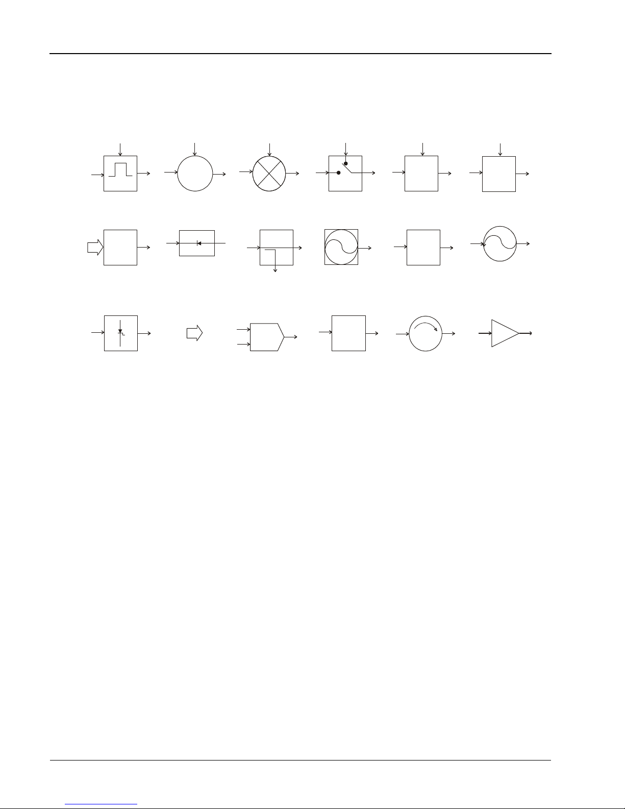
Symbols
Block diagram symbols frequently used in the manual are illustrated below.
Course
MOD
Pulse
Modulator
DAC
Digital to
Analog
Converter
Step-Recovery
Diode Multiplier
Fine
YIG-Tuned
Oscillator
RF Level
Detector
Digital
YIG
Data
Mixer
Coupler
V
R
Phase Lock
Loop
Switch
Fixed
Reference
Oscillator
DIV
N
Frequency
Divider
STEP
ATTEN
Step
Attenuator
LOW
PASS
Filter
Isolator
LVL
PIN-Diode
Leveler
Voltage-
Controlled
Oscillator
Amplifier
xii
Manual No. 20790, Rev C, November 1998

Record of Manual Changes
This table is provided for your convenience to maintain a permanent record of manual change d ata.
Corrected replacement pages will be issued as Technical Publication Change Instruction s, and will
be inserted at the front of the binder. Rem ove the corresponding old pages, insert the new pages,
and record the changes here.
Change Instruction
Number
Change Instruction
Date
Date
Entered Comments
Manual No. 20790, Rev C, November 1998
xiii

Series 8500A Peak Power Meters
xiv
Manual No. 20790, Rev C, November 1998

Special Configurations
When the accompanying product has been configured for user-specific application(s), supplemental
pages will be inserted at the front of the manual binder. Remove this page and replace it with the
furnished Special Configuration supplemental page(s).
Manual No. 20790, Rev C, November 1998
xv

Series 8500A Peak Power Meters
xvi
Manual No. 20790, Rev C, November 1998

1.1 Description
The Giga-tronics 8500A Series Peak Power Meters (PPM) are designed for the analysis and power
measurement of pulsed RF and microwave signals produced by microwave component devices.
The PPM converts RF energy to dc voltage by using balanced (dual Schottky diode), zero-biased,
detectors with very fast rise times. The dc voltage is measured with an autoranging dc amplifier, and an
A/D converter provides the digitized voltage to a MC68000 microprocessor. The microprocessor
accomplishes the required log functions, diode linearization, frequency response, and other
mathematical functions.
The PPM can measure the power in both single and repetitive pulses as well as the power in a CW
signal. Power measurements are presented on an Electro Luminescent (EL) screen to display both
alphanumeric and graphic information. Modes of operation are indicated both by information on the
display and by LED lights on the front panel. Changes in mode or test parameters can be accomplished
with the front panel keypad or, for some operations, the large spin knob on the front panel, which can
be used as an analog adjustment for certain parameters.
1
1
11
IIIInnnnttttrrrroooodddduuuuccccttttiiiioooonnnn
GPIB (IEEE Bus) setup and measurement operation are standard in the 8500A power meters. It enables
various other functions, such as reporting of errors, malfunctions, operational status, and self test
diagnostics.
The Model 8501A has a single detector input; Model 8502A has dual detector inputs for making ratio
measurements. All technical and operation descriptions in this manual apply equally to both models
unless otherwise stated.
Performance specifications for the Series 8500A are in Sectio n 1.2. Detector specifications are
contained in Appendix D. Options, if any will be detailed in Appendix E.
Power requirements are 100/120/220/240 Vac ±10%, 48-400 Hz. See Section 2.2 for Safety Precautions
and details to set the voltage and install the correct fuse for the area in which the instrument will be
used.
Manual 20790, Rev. C, November 1998 1-1

Series 8500A Peak Power Meters
1.1.1 Environmental Requirements
Series 8500A power meters are type tested to MIL-T-28800E, Type III, Class 5, Style E for Navy
shipboard, submarine, and shore applications except as follows:
• Operating temperature range is 0 °C to 50 °C (calibrator operating temperature range is 5 °C to
35 °C).
• Non-operating (storage) temperature range is -4 0°C to +7 0°C.
• Relative humidity is limited to 95% non-condensing.
• Altitude and EMI requirements are not specified.
1.1.2 Items Furnished
In addition to options and/or accessories specifically ordered, items furnished with the instrument are:
1 ea. - Power Cord
1 ea. - Detachable Detector Cable (for Model 8501A), or
2 ea. - Detachable Detector Cables (for Model 8502A)
1 ea. - Operation and Maintenance Manual
1.1.3 Items Required
The 8500A requires an external power detector; see Appendix D for power detector specifications.
1.1.4 Tools and Test Equipment
No special tools are required to operate the Series 8500A. Test equipment required for calibration or
performance verification is described in Chapter 4.
1.1.5 Cooling
No cooling is required if the instrument is operated within its specified operating temperature range
(0 to 50 °C).
1.1.6 Cleaning
The front panel can be cleaned using a cloth dampened with a mild detergent; wipe off the detergent
residue with a damp cloth and dry with a dry cloth. Solvents and abrasive cleaners should not be used.
1.1.7 Receiving Inspection
Use care in removing the instrument from the carton and check immediately for physical damage, such
as bent or broken connectors on the front and rear panels, dents or scratches on the panels, broken
extractor handles, etc. Check the shipping carton for evidence of physical damage and immediately
report any damage to the shipping carrier.
Each Giga-tronics instrument must pass rigorous inspections and tests prior to shipment. Upon receipt,
its performance should be verified to ensure that operation has not been impaired during shipment. The
performance verification procedure is described in Chapter 5 of this manual.
1-2 Manual 20790, Rev. C, November 1998

1.1.8 Returning an Instrument
If you are returning an instrument to Giga-tronics for any reason, including service, first contact
Giga-tronics Customer Service at (800) 444-2878 or Fax at (925) 328-4702 so that a return
authorization number can be assigned. You can also contact Customer Service over their e-mail address
repairs@gigatronics.com.
To protect the instrument during reshipment, use the best packaging materials available. If possible use
the original shipping container. If this is not possible, a strong carton or a wooden box should be used.
Wrap the instrument in heavy paper or plastic before placing it in the shipping container. Completely
fill the areas on all sides of the instrument with packaging material. Take extra precautions to protect
the front and rear panels.
Seal the package with strong tape or metal bands. Mark the outside of the package “FRAGILE —
DELICATE INSTRUMENT”. If corresponding with the factory or local Giga-tronics sales
office regarding reshipment, please reference the full model number and serial number. If the instrument
is being reshipped for repair, enclose all available pertinent data regarding the problem that has been
found.
Introduction
Manual 20790, Rev. C, November 1998 1-3

Series 8500A Peak Power Meters
1.2 System Specifications
Frequency Range
Power Range
Pulse Mode: -20 to +20 dBm
CW Mode: -40 to +20 dBm
Absolute Maximum Limit: +23 dBm (200 mW)
Accuracy
Calibrator Power Uncertainty
(at 0 dBm): ±1.5% (0.065 dBm)
Linearity after Automatic
Calibration: ±3% (at stable temperature)
Temperature coefficient of
linearity at ambien t±5 °C, CW
and Peak, typical: >-10dBm negligible, 0 to 50 °C
Uncertainty
(due to zeroing and noise): CW: <±10 nW, 15 to 50 °C (Avg. = 500) <±20 nW, 0 to 15 °C
30 MHz to 40 GHz depending on detectors
(See the Detector Specifications in Appendix D)
(Direct input to detector):
The uncertainty of microwave power measurements depends on
several factors, the most important is the effective mismatch of
both the power detector and the RF source. Excluding mismatch
effects, the measurement uncertainties of the instrument and its
power detectors are as follows:
<-10 dBm ±0.5%/deg.C, 15 to 50 °C
±1.0%/deg.C, 0 to 15 °C
(The instrument indicates if the ±5 °C calibration range is
exceeded)
Peak: <±3.5 mW, 15 to 50 °C (Avg. = 100) <±5.0 mW, 0 to 15 °C
Single Pulse: <±15 mW, 15 to 50 °C (typical)
Time Base Range
Graph Mode: 1.2 ns/DIV to 20 ms/DIV (12 ns to 20 0ms time window using
Resolution: 0.1 ns
Accuracy: 0to10ms,±0.2%±1ns;10msto5ms,±0.1%;5msto
1-4 Manual 20790, Rev. C, November 1998
<±30 mW, 0 to 15 °C (typical)
either the Data Entry keyboard or the spin knob)
200 ms, ±0.01%

Trigger Delay
Introduction
Range: 0 to 200 ms, using either the Data Entry keyboard or the spin
Resolution: 0.1 ns
Accuracy: 0to10ms,±0.2%±1ns;10msto5ms,±0.1%;5msto
Triggering Modes
Internal:
Duty Cycle: <50%
Trigger Rate:
External:
Graph Display Mode
Fast Measurement Mode
knob
200 ms, ±0.01%
-20dBmto+16dBmlimitedto>2dBand<20dBbelowthepeak
level of the signal.
10 Hz to 10 MHz
TTL levels, Max PRF = 1 MHz
Plots the outline of the detected pulse on the EL display. Also
provides readout of amplitude and timing information.
Available under GPIB control to provide fast data acquisitionand
output.
For an averaging number = 1, typically will be between 70 and
120 measurements/second.
Calibrator Specifications
Frequency:
Power Uncertainty at 1mW:
Return Loss at 1 mW:
Self Calibration Time:
Connector: Type N
Also can be used to provide fast data acquisition and throughput
via a rear panel analog output for using an 8500A with a network
analyzer to make swept frequency response tests.
1GHz±5%
±1.5%
Greater than 25 dB
Less than 1 minute
Manual 20790, Rev. C, November 1998 1-5

Series 8500A Peak Power Meters
Auxiliary Inputs/Outputs
Monitor: Provides a voltage proportional to the detected RF envelope.
Rise time is typically 20 ns, output impedance is nominally 50
ohms.
Analog Output Coefficient: 100 mV/dB ±0.5 mV (0 V = 0 dBm)
Offset: ±10 mV
Trigger Input:
TTL
RF Blanking: TTL open collector low during zeroing. Used to control power
source.
F:
V
PROP
(V/GHz) Allows direct entry of frequency from RF power sources
equipped with a VpropF output.
GPIB Interface: Per IEEE STD 488-1978
GPIB Indicators:
Remote Operation
REM, TLK, LSN, SRQ, LLO
Complete setup and measurement capabilities accessible via
GPIB (IEEE 488). Reporting of errors, malfunctions, operational
status, and self-test diagnostics available through serial poll
capability.
Direct Plot Output:
Outputs hardcopy pulse profile plots, with time, date and part
identification, to a GPIB plotter.
GPIB Address: Selectable from front panel
IEEE Interface Functions:
SH1, AH1, T6, L4, SR1, RL1, PP0, DC1, DT1, TE0, LE0
General Specifications
Stored Setups:
Saves settings at power down, and has 10 additional setups in
non-volatile memory.
Power-On Self-Test (POST):
POST is optionally performed at any time. A diagnostic code
indicates the cause and location of any errors.
Reset Control
(rear panel): Returns the instrument to preset (default) condition.
Design and Construction: To the intent of MIL-T-28800C,Type III, Class 5, Style E or F,
Color R
Power Requirements: 100, 120, 220, or 240 Vac ±10%, 50, 60, or 400 Hz ±5%
Power Consumption: Approximately 100 VA
Operating Temperature:
Non-operating Temperature:
0 to 50 °C (32 to 122 °F)
-40 to +65 °C (-40 to +149 °F)
1-6 Manual 20790, Rev. C, November 1998

Operating Humidity
(without precipitation):
Dimensions:
Introduction
95%, ±5% to 30 °C
75%,±5%to40°C
45%,±5%to50°C
Bench Mount:
Rack Mount:
With Feet:
Without Feet:
148.3 x 425.7 x 355.6 mm
132.6 x 425.7 x 355.6 mm
132.6 x 482.6 x 355.6 mm (5.22 x 19.00 x 14.00 in.)
(5.84 x 16.76 x 14.00 in.)
(5.22 x 16.76 x 14.00 in.)
Conforms to EIA RS-310 Standard for a 19-inch rack.
Weight:
Model 8501A:
Model 8502A:
12 kg (26 lbs)
13 kg (28 lbs)
Depending upon requirements, the following software versions and enhancements apply (See Table 1-1).
Table 1-1: 8500A Functions Related to Software Versions
S/W Version Sound Works Fast Analog
2.10A YES
2.11A
2.13A YES YES
2.14A YES YES YES
S-Mode
(FAA)
Menu Wrap
Manual 20790, Rev. C, November 1998 1-7

Series 8500A Peak Power Meters
1.3 Default Settings
Factory-programmed settings of various user definable functions have the following defaults whenever
there have been no changes made in the settings by the operator during any testing routines.
Function Default Setting
Averaging CW: 4 samples; Peak: 4 samples
Internal Trigger Level (A & B) -10 dBm
Frequency 1.00 GHz
Offset 0 dB
Cursor Delay (A & B ) 1.0000 microseconds
Start Delay 0.0000 nanoseconds
Delay Window (A & B) 10.0000 microseconds
Reference Power Level (A & B) 0 dBm
Reference Delay (A & B) 0.0000 microseconds
Cal Factor 0 dB
Mode Channel A, CW power, dBm
Trigger Mode Channel A, Internal
Pulse Width Start 50%
Pulse Width End 50%
Rise Time Start 10%
Rise Time End 90%
Fall Time Start 90%
Fall Time End 10%
Marker 1 2.5% (A and B)
Marker 2 17.8% (A and B)
Marker 3 46.9% (A and B)
Marker 4 90% (A and B)
The following settings are not affected by power-on, initialization, and setup store or recall:
Maximum Power +20.5 d Bm
Minimum Power -45.0 dBm
Autoscale Average Number 4
Autoscale Initial Delay 75 µs
Plotter Address 6
PPM Address 4
SourceofFrequency Correction a) User supplied (as input, default = 1GHz)
Frequency Display Displayed
1-8 Manual 20790, Rev. C, November 1998
b) VpropF - parameters not subject to store/
recall or initialization
c) Cal Factor - not subject to store/recall or
initialization

2.1 General
The Series 8500A Peak Power Meters are very simple to operate. You only need to follow the instructions
given in the prompts and menus shown in the display window to set up the parameters for making a
measurement. Eleven levels of operational menus are available. Each can be accessed with the MENU
key. The type of measurement (Peak or CW) being made will also be shown in the lower right corner of
the display to identify the mode in u se.
Along with the menus and prompts in the display, the power meters produce audible clicks and beeps to
indicate the occurrence (or non-occurrence) of certain events during setup and testing. The tones are
defined as follows:
Click: When a key is pressed and a click is heard, this means that the key is active and its
2
Operation
function will be included in the parameters being entered. If no click is heard, the
key is not active and not performing any function at that time.
Beep: A single beep indicates that the calibration, zeroing, or self-test functions have
There is a volume control on the rear panel of the instrument. It adjusts the audio tones to a comfo rtable
level, or the audio can be turned off if desired.
☛ NOTE:
8502A, the instrument may be referred to as the PPM (Peak Power Meter).
2.2 Installation
The unit is set at the factory for operation at the normal supply voltage for the country in wh ich it is
sold. The input frequency must be 50, 60, or 400 Hz ±5%. The combination of the module and
transformer design allows instrument operatio n of 100/120 volts with a 2.0 A Slo-Blo fuse, or 220/240
volts with a 1.0 A Slo-Blo fuse.
Before applying ac power to the instrument, be sure that the instrument is set for
the correct li ne vo l ta ge a nd th at t he fus e s a re of t he co rrect rat i ng.
successfully completed when they are performed. A double beep means that the
function failed to complete. The discussion of these functions later in this chapter
will detail what problems might cause the function to fail.
In the remainder of this chapter except where specified as the Model 8501A or
WARNING
Figure 2-4 illustrates the rear panel. Before operating the instrument, make sure the input voltage is
correctly set and that the fuses are compatible with the applied line voltage.
Manual No. 20790, Rev C, November 1998
2-1
Series 8500A Peak Power Meters
☛ NOTE:
The 8500A may be furnished with the PC-oriented voltage selector and fuse holder
described next, or the VDE-approved fuse holder described in the following pages. Refer
to the appropriate type of voltage selector and fuse holder for your power meter.
CAUTION
The instrument may be damaged if you turn it on while the voltage selector and
fuses are incorrect for the applied line voltage.
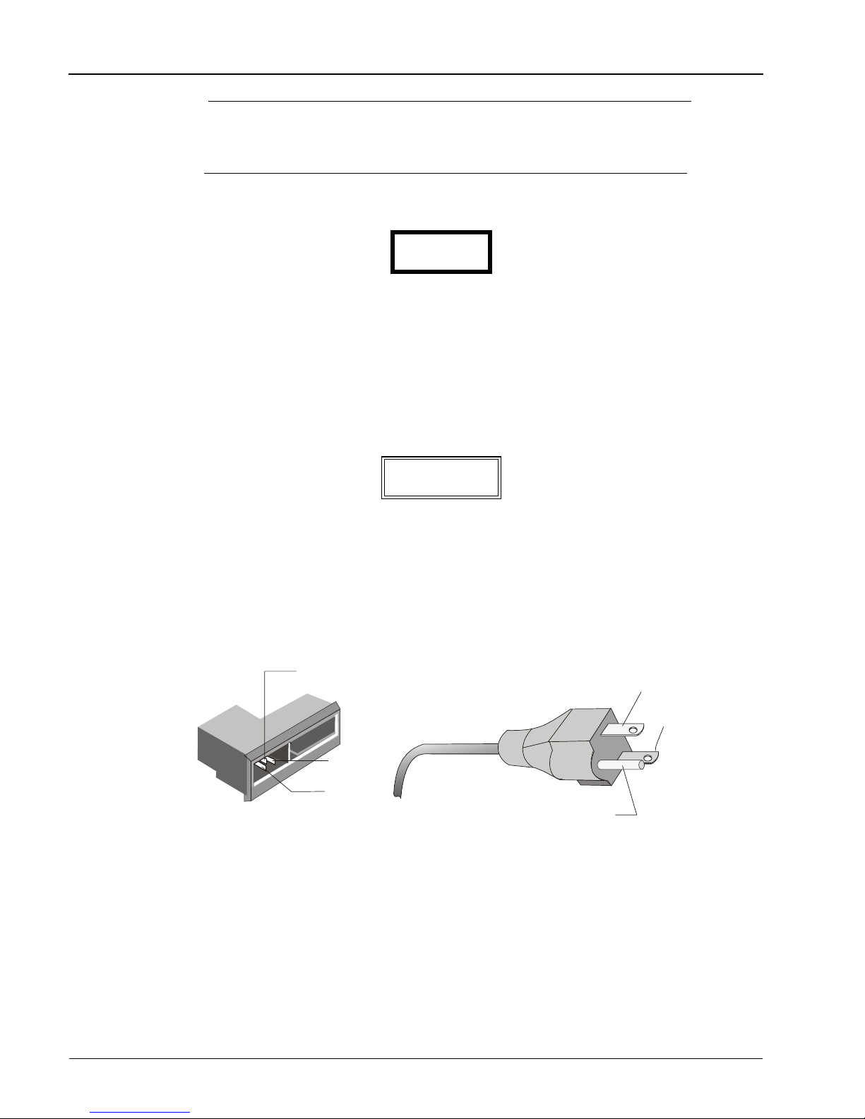
The power meter is supplied with a three-conductor NEMA type power cord for connection to the power
source and safety ground, as illustrated in Figure 2-1. The current carrying conductor is black and its
return is white. The green wire of the power cord is for connection to earth ground. The instrument will
be properly ground ed if the plug is connected to a proper ly installed three-prong rece ptacle. If a
three-prong to two-prong adapter is used, be su re that the pigtail lead of the adapter is earth-grounded.
WARNING
The safety ground is connected directly to the chassis. If a 3-to-2 wire adapter is
to be used, be sure to connect the ground lead from the adapter to earth ground.
Failure to do this could cause the instrument to float above ground, posing a shock
hazard.
2-2
EARTH GROUND
LINE
NEUTRAL
LINE
NEUTRAL
EARTH GROUND
Figure 2-1. Power Connector
Manual No. 20790, Rev C, November 1998
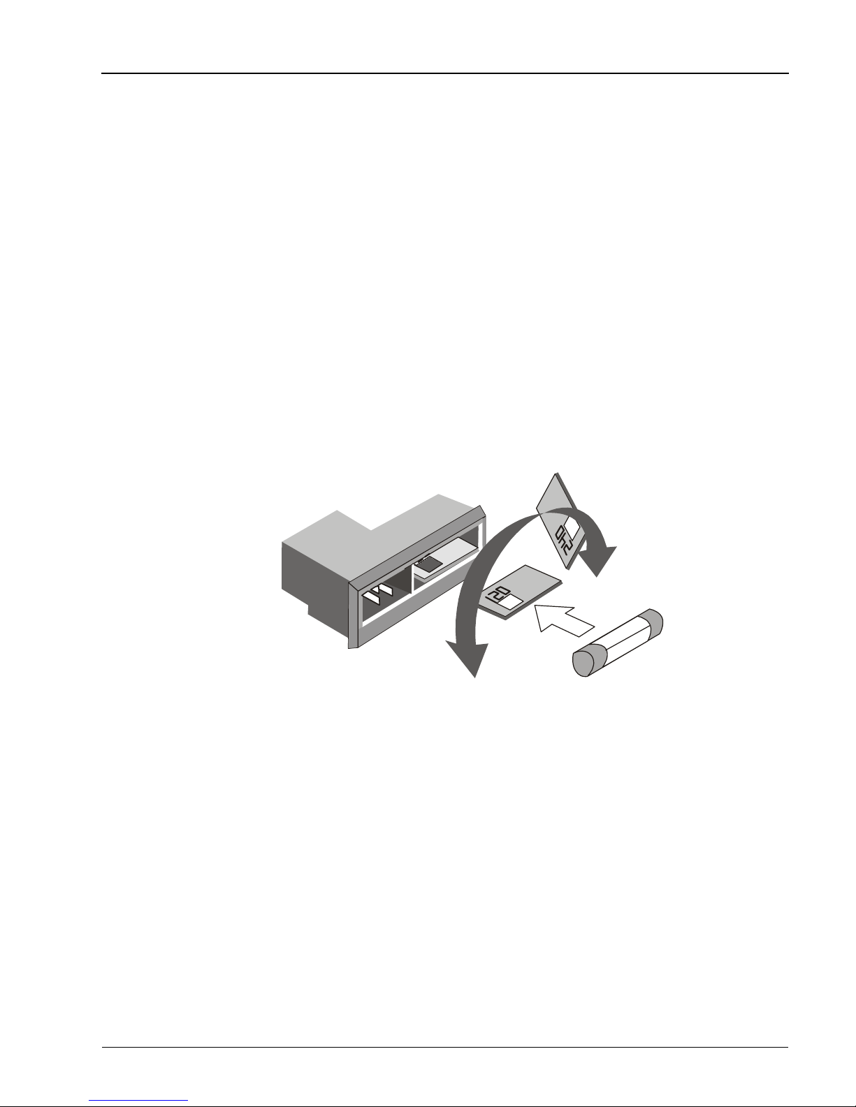
2.2.1 PCB-Oriented Voltage Selector and Fuse Holder
The number on the selector card, visible through the window, indicates the nominal line voltage to which
the power meter must be connected.
The line voltages and fuse ratings are:
Line Voltage Fuse Rating
100/120 Vac, ±10%, 50, 60 or 400 Hz ±5% 1.0 AMP Slo -Blo
220/240 Vac, ±10%, 50, 60 or 400 Hz ±5% 2.0 AMP Slo -Blo
To select a different operating line voltage and fuse, refer to Figure 2-2 and proceed as follows:
1. Op en the cover door, rotate the fuse-pull to the left, and remove the fuse.
2. Select the operating voltage by orienting the PC board so that the correct voltage label is on the
top left side.
3. Pu sh the board firmly back into the module slot.
4. R otate the fuse-pull back into the normal position and reinsert the fuse into the holder. Use care
to select the correct fuse value.
Operation
Operating v oltage is shown
in the module w ind ow
Manual No. 20790, Rev C, November 1998
Figure 2-2. PCB Voltage Selector and Fuse Holder
2-3
Series 8500A Peak Power Meters
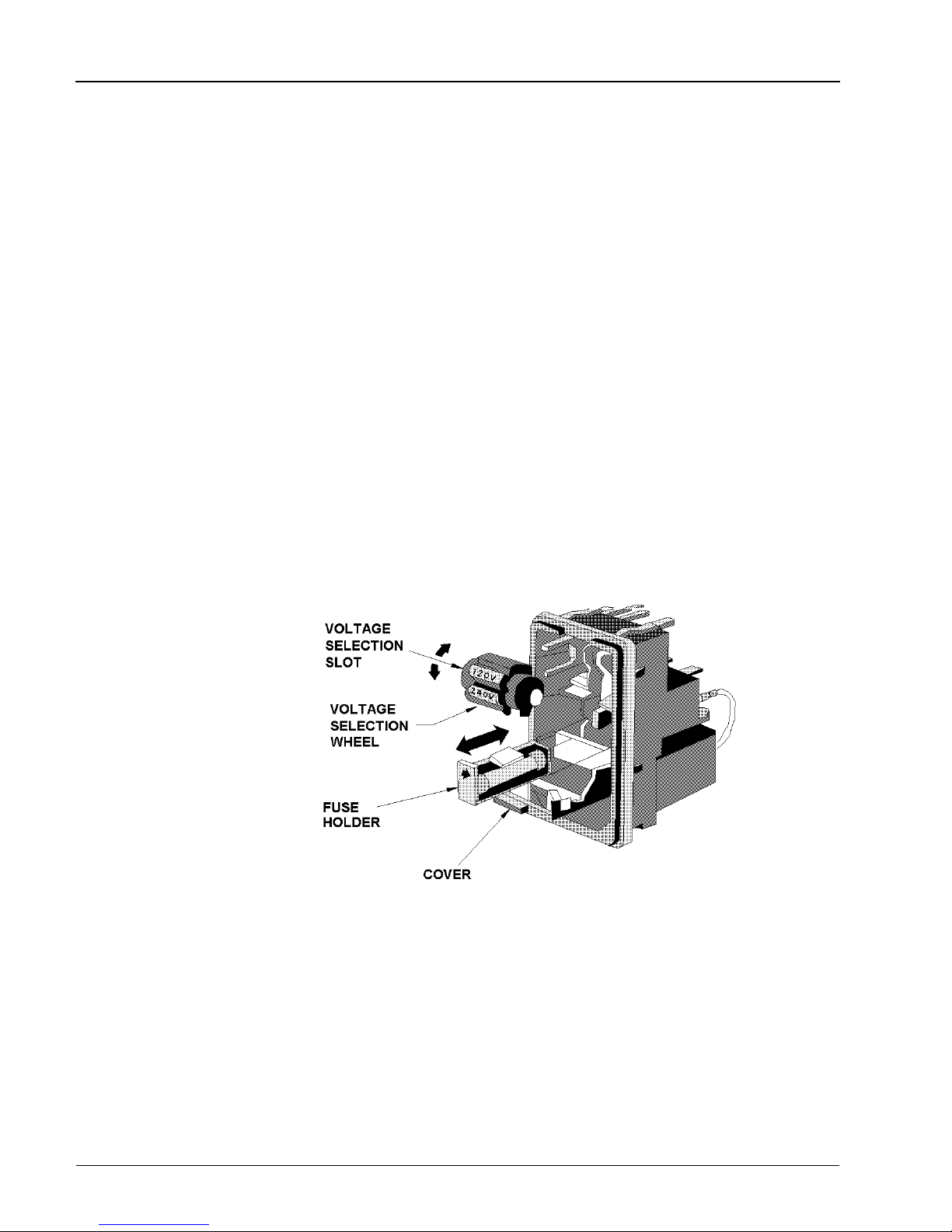
2.2.2 VDE Type Voltage and Fuse Holder
The VDE-approved voltage selector and fuse holder are contained in a covered housing directly above the
ac power connecter.
The line voltages and fuse ratings are:
Line Voltage Fuse Rating
100/120 Vac, ±10%, 50, 60 or 400 Hz ±5% 1.0 AMP Slo -Blo
220/240 Vac, ±10%, 50, 60 or 400 Hz ±5% 2.0 AMP Slo-Blo
To gain access to the voltage selector and fuse, open the cover with a small screwdriver or similar tool
and proceed as follows:
To change the voltage setting:
Use the same tool to remove the voltage selector (a small barrel-shaped component marked with voltage
settings). Rotate the selector so that the desired voltage faces outward and place the selector back in its
slot. Close the h ousing cover; the ap propriate voltage shou ld be visible thro ugh the window (see
Figure 2-3).
To replace the fuse :
With the housing cover open, pull out the small drawer on the right side of the housing (marked with an
arrow) and remove the old fuse. Replace with a new fuse, insert the drawer and close the housing cover
(see Figure 2-3).
Figure 2-3. VDE Voltage Selector and Fuse Holder
2-4
Manual No. 20790, Rev C, November 1998
 Loading...