

Giga-tronics 80350A, 80353A, 80354A, 80355A, 80351A Operation & Maintenance Manual
...
Manual Part Number:
Revision:
Print Date:
21568
F
March 2008
Series 8035XA Peak Power Sensors
Operation & Maintenance Manual
8035XA
............................................Certified Product
Registrar: BSI, Certification No. FM 34226 v Registered 04 June 1996 v Amended 01 March 2000
Giga-tronics Incorporated v 4650 Norris Canyon Road v San Ramon, California 94583
925.328.4650 or 800.726.4442 v 925.328.4700 (Fax) v 800.444.2878 (Customer Service) v 925.328.4702 (CS Fax)
www.gigatronics.com
ISO 9001.................................................. Certified Process

All technical data and specifications in this manual are subject to change without prior notice and do not represe nt a
commitment on the part of Giga-tronics Incorporated.
© 2001 Giga-tronics Incorporated. All rights reserved.
Printed in the USA
WARRANTY
Giga-tronics Series 8035XA Peak Power Sensors
are warranted against defective materials and
workmanship for one years from date of shipment .
Giga-tronics will at its option repair or replace
products that are proven defective during the
warranty period. This warranty DOES NOT cover
damage resulting from improper use, nor
workmanship other than Giga-tronics service.
There is no implied warranty of fitness for a
particular purpose, nor is Giga-tronics liable f or any
consequential damages. Specification and price
change privileges are reserved by Giga-tronics.

Declaration of Conformity
Application of Council Directive(s)
Standard(s) to which Conformity is Declared:
89/336/EEC and 73/23/EEC EMC Directive and Low Voltage Directive
EN61010-1 (1993) Electrical Safety
EN61326-1 (1997) EMC - Emissions & Immunity
Manufacturer’s Name: Manufacturer’s Address:
Giga-tronics, Incorporated 4650 Norris Canyon Road
San Ramon, California 94583
U.S.A.
Type of Equipment: Model Series Number:
Peak Power Sensors 8035XA
Model Numbers In Series:
80350A, 80351A, 80352A,
80353A, 80354A, 80355A
Declaration of Conformity on file. Contact Giga-tronics, Inc.
4650 Norris Canyon Rd.
San Ramon, CA 94583
Ph: 1-925-328-4650
Fx: 1-925-328-4700


1
Introduction
2
Operation
Table of Contents
About This Manual .................................................................................................. 1-vii
Conventions ........................................................................................................... 1-viii
Record of Manual Changes ........................................................................................1-x
Special Configurations ..............................................................................................1-xi
1.1 Description....................................................................................................1-1
1.1.1 Accessories ..................................................................................1-1
1.1.2 Product Returns ...........................................................................1-1
1.2 Specifications ...............................................................................................1-2
1.2.1 Performance Specifications ...........................................................1-3
1.2.2 Compatible Power Meters ............................................................1-5
3
2.1 Introduction ..................................................................................................2-1
2.2 Power Sweep Calibration ..............................................................................2-1
2.2.1 5, 25 and 50 Watt Peak Power Sensors ........................................2-2
2.2.2 Triggering .....................................................................................2-3
2.2.3 Zeroing .........................................................................................2-4
2.2.4 Sensor Triggering .........................................................................2-5
2.3 Sample Delay ................................................................................................2-6
2.3.1 Sample Delay Display ...................................................................2-7
2.3.2 Setting Sample Delay ...................................................................2-8
2.3.3 Sample Delay Limits .....................................................................2-9
2.3.4 Setting Sample Delay Offset .......................................................2-10
2.3.5 Single Peak Sample Measurements ............................................2-10
2.3.6 Real Time Pulse Profile and Sample Position Display ..................2-11
2.3.7 Sample Delay Offset ...................................................................2-12
2.3.8 Measuring Pulse Droop ..............................................................2-13
2.3.9 Measuring 3 dB Pulse Width ......................................................2-14
2.3.10 Measuring Rise-Time ..................................................................2-15
2.4 GPIB Commands.........................................................................................2-15
2.4.1 Setting Trigger Modes ................................................................2-15
2.4.2 Setting Delays ............................................................................2-16
2.4.3 Reading Values ...........................................................................2-17
2.4.4 Commands for the 58542 ...........................................................2-18
Theory of Operation
Manual 21568, Rev. F, March 2008 i

Series 8035XA Peak Power Sensors
3.1 Introduction...................................................................................................3-1
3.2 Analog Assembly Description........................................................................3-2
3.3 Digital Assembly Description.........................................................................3-5
3.3.1 Overview ......................................................................................3-5
3.3.2 Description ...................................................................................3-6
Calibration and Testing
4.1 Introduction...................................................................................................4-1
4.2 Equipment Required......................................................................................4-1
4
4.3 Power Linearity Test......................................................................................4-2
4.3.1 CW Linearity Test .........................................................................4-2
4.3.2 Peak Linearity Test ........................................................................4-3
4.4 Trigger Modes Tests .....................................................................................4-4
4.4.1 Detector Output Test ....................................................................4-4
4.4.2 Trigger Level Test .........................................................................4-4
4.4.3 Delay Test ....................................................................................4-6
4.4.2.1 100 mW Power Peak Sensors..................................... 4-4
4.4.2.2 High Power Peak Sensors........................................... 4-5
Maintenance
5
6
Parts Lists
5.1 Introduction...................................................................................................5-1
5.1.1 Rise-Time Adjustments .................................................................5-1
5.1.2 Zero Adjustment ...........................................................................5-2
5.2 Troubleshooting ............................................................................................5-2
5.2.1 Sensor Not Present .......................................................................5-4
5.2.2 Calibration ....................................................................................5-4
5.2.3 INTernal ........................................................................................5-5
5.2.4 EXTernal .......................................................................................5-6
5.2.5 Delay ............................................................................................5-6
5.2.6 Output Problems ..........................................................................5-6
5.3 Sensor Element Replacement ........................................................................5-7
5.3.1 Disassembly of the Sensor ...........................................................5-7
5.3.2 Replacing the Sensor Element ......................................................5-7
5.3.3 Reassembly of the Sensor ............................................................5-8
6.1 Introduction...................................................................................................6-1
80350A PEAK POWER SENSOR, TYPE N, Rev. F....................................... 6-1
80351A HI PWR PEAK POWER SENSOR, 5W, Rev. C................................ 6-2
80352A HI PWR PEAK POWER SENSOR, 25W, Rev. C.............................. 6-3
80353A PEAK POWER SENSOR, TYPE K, Rev. D....................................... 6-4
80354A PEAK POWER SENSOR, TYPE K, Rev. E....................................... 6-5
80355A HI PWR PEAK POWER SENSOR, 50W, Rev. C.............................. 6-6
32133 SENSOR-S-CLOCK-BUFFER PCA, Rev. A...................................... 6-6
21471 SENSOR HOUSING ASSY, Rev. C................................................. 6-7
ii Manual 21568, Rev. F, March 2008

7
Diagrams
Index
Preface
21350 ANALOG PCB ASSY (A1), Rev. P.................................................. 6-8
21353 DIGITAL PCB ASSY (A2), Rev. Z................................................. 6-10
6.2 List of Manufacturers..................................................................................6-12
7.1 Introduction ..................................................................................................7-1
Series 8035XA Peak Power Sensors Index........................................................... Index-1
Manual 21568, Rev. F, March 2008 iii

Series 8035XA Peak Power Sensors
Illustrations
Figure 2-1: Sensor Setup Menu Tree ......................................................................2-2
Figure 2-2: Internal Triggering Levels......................................................................2-3
Figure 2-3: 8035XA Sensor Timing Diagram...........................................................2-4
Figure 2-4: Sample Delay Adjustment Display ........................................................2-6
Figure 2-5: Channel A Default Sample Delay ..........................................................2-7
Figure 2-6: Channel B Default Sample Delay...........................................................2-7
Figure 2-7: Channel A & B Default Sample Delay....................................................2-7
Figure 2-8: Sample Delay with Uncalibrated Sensor ...............................................2-7
Figure 2-9: Sample Delay with No Trigger Display..................................................2-9
Figure 2-10: Sample Dely Over-Range Indication......................................................2-9
Figure 2-11: Sample Delay Over-Range Offset Display............................................2-10
Figure 2-12: Pulse Profile and Sample Delay Test Setup.........................................2-11
Figure 2-13: Sample Delay......................................................................................2-12
Figure 2-14: Using SD to Offset a 0 ns Time Reference...........................................2-12
Figure 2-15: SD Setting for Measuring Pulse Droop................................................2-13
Figure 2-16: Using SD to Measure a 3 dB Pulse Width...........................................2-14
Figure 3-1: 8035XA High Level Block Diagram........................................................3-2
Figure 3-2: Analog PC Assembly Block Diagram.....................................................3-3
Figure 3-3: Analog Circuit Timing Diagram.............................................................3-4
Figure 3-4: Digital PC Assembly Block Diagram......................................................3-5
Figure 3-5: Digital Timing Diagram, INT/EXT Trig Mode..........................................3-7
Figure 3-6: Digital Timing Diagram, CW Mode .......................................................3-8
Figure 3-7: Digital Serial Data Cycle Timing Diagram..............................................3-8
Figure 4-8: Power Linearity Test Setup...................................................................4-2
Figure 4-9: Detector Output and Trigger Level Setup..............................................4-4
Figure 5-10: Principal Test Component Locations.....................................................5-2
iv Manual 21568, Rev. F March 2008

Tables
Preface
Table 1-1: Peak Power Sensor Selection Guide..................................................... 1-2
Table 1-2: Power Sensor Cal Factor Uncertainties ................................................ 1-5
Table 6: Sample Delay Limits ............................................................................ 4-6
Table 7: 80350A, 80353A, 80354A Trigger Test............................................... 4-9
Table 8: 80351A Trigger Test............................................................................ 4-9
Table 9: 80352A, 80355A Trigger Verification................................................... 4-9
Table 10: External Trigger Verification................................................................. 4-9
Table 11: Sample Delay Test............................................................................. 4-10
Table 5-1: Sensor Malfunction Symptoms............................................................ 5-3
Table 5-2: Digital Board Components and Signals................................................ 5-6
Table 6-1: List of Manufacturers ........................................................................ 6-12
Manual 21568, Rev. F, March 2008

Series 8035XA Peak Power Sensors
vi Manual 21568, Rev. F, March 2008

About This Manual
This manual contains the following chapters and appendices to describe the operation and
maintenance of Giga-tronics Series 8035XA Peak Power Sensors:
Preface:
In addition to a comprehensive Table of Contents and general information abou t the manual,
the Preface also contains a record of changes made to the manual since its publication, an d
a description of Special Configurations. If you have ordered a user-specific manual, please
refer to page
Chapter 1 – Introduction:
This chapter contains a brief introduction to the instrument and its performance parameters.
Chapter 2 – Operation:
This chapter is a guide to operating the sensor with the Series 8540X Universal Power
Meters and the Model 58542 VXIbus Universal Power Meters.
Chapter 3 – Theory of Operation:
xi for a description of the special configuration.
This chapter provides a block diagram level description and its circuits for maintenance and
applications.
Chapter 4 – Calibration & Testing:
Procedures for inspection, calibration and performance testing are outlined in this chapter.
Chapter 5 – Maintenance:
This chapter contains procedures for main te na nce and troubleshooting.
Chapter 6 – Parts Lists:
This chapter lists all components and parts and their sources.
Chapter 7 – Diagrams:
This chapter contains schematics and parts placement diagrams for all circuits.
Index:
A comprehensive word index of the various elements of the 8035XA manual.
Changes that occur after publication of the manual, and Special Configuration data will be
inserted as loose pages in the manual binder. Please insert and/or replace the indicated
pages as detailed in the Technical Publication Change Instructions included with new and
replacement pages.
Manual 21568, Rev. F, March 2008

Series 8035XA Peak Power Sensors
The following conventions are used in this product manual. Additional conventions not included
here will be defined at the time of usage.
Warning
The WARNING statement is encased in gray and centered in the
page. This calls attention to a situation, or an operating or
maintenance procedure, or practice, which if not strictly corrected
or observed, could result in injury or death of personnel. An
example is the proximity of high voltage.
Caution
Conventions
WARNING
CAUTION
The CAUTION statement is enclosed with s ingle lines and c entered
in the page. This calls attention to a situation, or an ope rating or
maintenance procedure, or practice, which if not strictly corrected
or observed, could result in temporary or permanent da mage to the
equipment, or loss of effectiveness.
Notes
*
Logic Not
A logic NOT or LOW condition used in text will be indicated by an overscore, such as LOADCTR. Elsewhere, such as in schematics, a logic NOT or LOW condition may be indicate d by a
forward slash bar, such as /LOAD-CTR.
Key Press Commands
Commands requiring specific keys to be pressed on the supporting device, such as power
meter, are indicated by square brackets. For example, [ENTER] means to press the Enter Key.
NOTE: A NOTE Highlights or amplifies an essential operating or maintenance procedure,
practice, condition or statement.
viii Manual 21568, Rev. F, March 2008

Manual 21568, Rev. F, March 2008

Series 8035XA Peak Power Sensors
This table is provided for your convenience to maintain a permanent record of manual change
data. Corrected replacement pages will be issued as Technical Publication Change
Instructions, and will be inserted at the front of the binder. Remove the corresponding old
pages, insert the new pages, and record the changes here.
Record of Manual Changes
Change Instruction
Number
Change Instruction
Date
Date
Entered
Comments
x Manual 21568, Rev. F, March 2008

Special Configurations
When the accompanying product has been configured for user-specific applicatio n(s),
supplemental pages will be inserted at the front of the manual binder. Remove the indicated
page(s) and replace it (them) with the furnished Special Configuration supplemental page(s).
Manual 21568, Rev. F, March 2008

Series 8035XA Peak Power Sensors
xii Manual 21568, Rev. F, March 2008

Manual 21568, Rev. F, March 2008

Series 8035XA Peak Power Sensors
xiv Manual 21568, Rev. F, March 2008

1.1 Description
The 8035XA Series Peak Power Sensors perform true sample-based peak power
measurements on pulsed signals. The sensors are compatible with Giga-tronics Series 8540,
and the 8650 series Universal Power Meters and the Model 58542 VXIbus Universal Power
Meter (see Section
power versions of 5, 25 and 50 Watts, are available to 18 GHz. (see Table 1-1).
Peak Power sensors have three modes of operation: (1) CW, (2) Peak, internally triggered , and
(3)
Peak, externally triggered. When operated in the pea k mode s, trigge r- point to sam ple- point
delay (sample delay) is adjustable from -20 ns to 100 ms in 0.5 ns steps. T rigger levels are also
adjustable.
The Giga-tronics proprietary power sweep calibration system provides excellent linearity from
-20 dBm to +20 dBm in Peak modes, and from -30 dBm to +20 dBm in CW mode. Cal Factors
stored in EEPROMs in the power sensors automatically compensate for sensor frequency
response variations. This unique approach can be configured for automatic frequency
response correction. A detector output signal is provided for viewing the detected envelope of
the pulsed RF waveform on an oscilloscope. Use of a digital oscilloscope is recommended.
1
Introduction
1.2.2). The sensors operate from 45 MHz to 18, 26.5, and 40 GHz. High
1.1.1 Accessories
Included: 3 each SMB (plug) to BNC (m) cables, 2 m (6 ft) long
Optional: Option 02: 12 ft SMB (plug) to BNC cable
1.1.2 Product Returns
Should it be necessary to return the product to Giga-tronics, use the original shipping container.
If this is not possible, use a strong carton (350 lbs/in
Wrap the instrument in heavy paper or plastic before placing it in the shipping container.
Completely fill the areas on all sides of the instrument with packaging material, taking extra
precautions to protect the front and rear panels. Seal the package with strong tape or metal
bands. Mark the outside of the package “FRAGILE — DELICATE INSTRUMENT”.
If corresponding with the factory or the local Giga-tronics sales office regarding a product
return, please refer to the full model number and serial number. If the instrument is being
3 each Cable Harness Wraps, 1.2 m (4 ft) long
Option 03: SMB (plug) to SMA (jack) adapter
2
bursting strength), or a wooden box.
Manual 21568, Rev. F, March 2008

Series 8035XA Peak Power Sensors
*
shipped for repair, be sure to enclose all available pertinent data regar ding the problem that
has been found.
NOTE: If you are returning an instrument to Giga-tronics for service, first contact Customer
Service so that a return authorization number (RMA) can be assigned via e-mail at
repairs@gigatronics.com or at 800.227-9764 (The 800 number is only valid within the US).
You may also try our domestic line at 925.328.4650 or Fax at 925.328.4702.
1.2 Specifications
Table 1-1: Peak Power Sensor Selection Guide
Model
80350A
80353A
80354A
80351A
80352A
Freq. Range/
Power Range
45 MHz to 18 GHz
-20 to +20 dBm, Peak
-30 to +20 dBm, CW
45 MHz to 26.5 GHz
-20 to +20 dBm, Peak
-30 to +20 dBm, CW
45 MHz to 40 GHz
-20 to +0.0 dBm, Peak
-30 to +0.0 dBm, CW
45 MHz to 18 GHz
0.0 to +40 dBm, Peak
-10 to +37 dBm, CW
45 MHz to 18 GHz
+10 to +50 dBm, Peak
0.0 to +44 dBm, CW
Max.
Power
+23 dBm
(200 mW)
CW or Peak
CW:
+37 dBm
(5 W Avg.)
Peak:
+43 dBm
CW:
+44 dBm
(25 W Avg.)
Peak:
dBm
+53
Power Linearity
Standard Peak Power Sensors
-30 to -20 dBm ±0.00 dB
-20 to +20 dBm ±0.05 dB/10 dB
-30 to -20 dBm ±0.00 dB
-20 to +20 dBm ±0.1 dB/10 dB
-30 to -20 dBm ±0.00 dB
-20 to 0.0 dBm ±0.2 dB/10dB
-10 to +0 dBm ±0.00 dB
+0 to +40 dBm ±0.05 dB/10 dB
0.0 to +10 dBm ±0.00 dB
+10 to +50 dBm ±0.05 dB/10 dB
4
5W Peak Power Sensor
25W Peak Power Sensor
50W Peak Power Sensor
Type
N(m)
50Ω
Type
K(m)
50Ω
2,5
Type
N(m)
50Ω
3,5
Type
N(m)
50Ω
3,5
RF
Conn
1
Dimensions
Ln. Dia.
165 mm
(6.5 in)
200 mm
(7.9 in)
229.6mm
(9.05 in)
37 mm
1.25 in)
37 mm
(1.25 in)
41.15
mm
(1.62 in)
Wgt VSWR
1.12:0.045 - 2 GHz
1.22:2 - 12.4 GHz
1.37:12.4 -18 GHz
1.12:0.045 - 2 GHz
1.22:2 - 12.4 GHz
0.3 kg
1.37:12.4 -18 GHz
(0.7 lb)
1.50:18 - 26.5 GHz
1.12:0.045 - 2 GHz
1.22:2 - 12.4 GHz
1.37:12.4 -18 GHz
1.50:18 - 26.5 GHz
1.92:26.5 - 40 GHz
1.15:0.045 - 4 GHz
0.4 kg
1.25:4 - 12.4 GHz
(0.9 lb)
1.35:12.4 -18 GHz
1.20:0.045 - 6 GHz
0.4 kg
1.30:6 - 12.4 GHz
(0.9 lb)
1.40:12.4 -18 GHz
CW:
+47 dBm
(50 W Avg.)
Peak:
+53 dBm
0.0 to +10 dBm ±0.00 dB
+10 to +50 dBm ±0.05 dB/10 dB
Type
N(m)
50Ω
287.7
mm
(11.35 in)
41.15
mm
(1.62 in)
0.9 kg
(1.1 lb)
1.25:0.045 - 6 GHz
1.35:6 - 12.4 GHz
1.45:12.4 -18 GHz
80355A
45 MHz to 18 GHz
+10 to +50 dBm, Peak
0.0 to +47 dBm, CW
Notes:
1. The K connector is electrically and mechanically compatible with the APC-3.5 and SMA connectors.
2. Power coefficient equals <0.01 dB/Watt (AVG).
3. Power coefficient equals <0.015 dB/Watt (AVG).
4. For frequencies above 8 GHz, add power linearity to system linearity.
5. Peak operating range above CW maximum range is limited to <10% duty cycle.
1-2 Manual 21568, Rev. F, March 2008

1.2.1 Performance Specifications
Performance specifications describe warranted performance. Typical performance shown in
italics is non-warranted. Specifications are subject to change without notice.
Rise-Time (10% to 90%, 0 dBm = 100%) < 100 ns
Fall Time (90% to 10%, 0 dBm = 100%) < 250 ns
System Linearity (50 MHz for Standard Peak Power Sensors:)
±0.13 dB from -30 to +16 dBm
±0.13 dB +(+0 dB, -0.05 dB/dB) from +16 to +20 dBm
Manual 21568, Rev. F, March 2008

Series 8035XA Peak Power Sensors
Zero Accuracy
Applies to 80350A, 80353A and 80354; 80351A = 100x larger,
80352A = 1000x larger
Zero Set: < ±1.0 mW, Peak;
Zero Drift: < ±1.0 mW, Peak
Noise Uncertainty: < ±1.0 mW, Peak;
Sample Delay Timing
Delay Range: -20 ns to 104 ms
Delay Resolution: 0.5 ns
Delay Jitter: ±2.0 ns
Trigger Level Set Range:
Internal: -30 to +20 dBm
Resolution: ±0.01 dB
External: 0.0V to 4.0V
Trigger Jitter: < ±2.0 ns
Settling Time: (50% to within 3%) < 250 ns
Control Inputs and Outputs
< ±0.05 mW, CW
< ±0.05 mW, CW
in 1 hour at constant temperature, 24 hour warmup
< ±0.05 mW, CW at constant temperature, measured over a 1
minute interval, 24 hour warmup
Resolution to 0.01V
Trigger Input: [SMB (jack) connector]
Detector Out: [SMB (jack) connector]
Sample Delay: [SMB (jack) connector]
TTL External Trigger Input (absolute maximum = 10 V)
110 kΩ Impedance.
Monitor real time pulse waveform on an oscilloscope with this
voltage output (uncalibrated)
(High Impedance - Do Not Terminate)
High, 5 V, between trigger and sample points. Connect to digital
oscilloscope channel 2 for triggering and sample point
identification
(High Impedance - Do Not Terminate)
Maximum cable length = 3 meters
1-4 Manual 21568, Rev. F, March 2008

Table 1-2: Power Sensor Cal Factor Uncertainties
Freq. (GHz) Sum of Uncertainties (%)
Lower Upper 8035XA
0.1 1 1.61 3.06 9.09 9.51 10.16 1.04 1.64 4.92
1 2 1.95 3.51 9.43 9.85 10.50 1.20 1.73 5.04
2 4 2.44 4.42 13.10 13.57 14.52 1.33 1.93 7.09
4 6 2.67 4.74 13.33 13.80 14.75 1.41 2.03 7.17
6 8 2.86 4.94 13.52 13.99 14.94 1.52 2.08 7.25
8 12.4 3.59 6.04 14.25 14.72 15.67 1.92 2.55 7.56
12.4 18 4.09 6.86 19.52 20.97 21.94 2.11 2.83 12.37
18 26.5 —— 9.27 —— —— —— —— 3.63 ——
26.5 40 —— 15.19 —— —— —— —— 6.05 ——
80353A
80354A
80351A
3
1
80352A
Probable Uncertainties (%)
3
80355A
3
8035XA
80353A
80354A
80351A
80352A
80355A
Notes:
1. Includes uncertainty of reference standard and transfer uncertainty. Directly traceable to NIST.
2. Square root of sum of the individual uncertainties squared (RSS).
3. Cal Factor numbers allow for 3% repeatability when connecting attenuator to sensor, and 3% for attenuator
measurement uncertainty and mismatch of sensor/pad combination. Attenuator frequency response is added to
the Sensor Cal Factors which are stored in the sensor’s EEPROM.
2
3
3
3
1.2.2 Compatible Power Meters
8541X Single Channel Universal Power Meter
8542X Dual Channel Universal Power Meter
8651A Single Channel Universal Power Meter
8652A Dual Channel Universal Power Meter
58542 Dual Channel VXI Universal Power Meter
NOTE: If the Series 8035XA sensors will be used with a Model 8542 (dual channel) Power
Meter, the 8542 must be configured to code 06 or higher, or an asterisk (*) must be appended
to the code number. The code number is printed next to the serial number on the label
located on the rear panel of the 8542.
Manual 21568, Rev. F, March 2008

Series 8035XA Peak Power Sensors
1-6 Manual 21568, Rev. F, March 2008

2.1 Introduction
When a sensor is first connected to a Model 8540 or 8650 Series Unive rsal Power Meter or to a
Model 58542 VXIbus Universal Power Meter, it is necessary to calibrate the sensor to the
meter’s sensor input, using the meter’s power sweep calibration system. The power meter will
not allow measurements to be performed until this calibration is completed successfully. It is a
good practice to repeat the calibration whenever the ambient operating temperature of the
sensor varies by more than ±5 °C (±9 °F), and whenever any external connections or external
loads are added or removed from the sensor. Always a llow a 30 minute warm-up perio d before
calibrating the sensor.
2
Operation
*
The operational description of the 8035XA Peak Power Sensor applies to applications with
either the Series 8540 or 8650 Universal Power Meters (8541 /2, B and C) or the Model 58542
VXIbus Universal Power Meter. Except where noted, the front panel descriptions apply only to
the Series 8540 Power Meters, and SCPI command sequences apply to the Model 58542
VXIbus Power Meter. The Series 8650 Power Meter display lines vary from the Series 8540 but
include the same parameters.
NOTE: These instructions show the Series 8540 Power Meter front panel keys in brackets
[ ] and menu displays in bold print.
2.2 Power Sweep Calibration
Procedures for calibrating sensors to the meter are detailed in the specific power meter
manual. The 8035XA Peak Power Sensors are calibrated to the meter using the same
procedure as other sensors used with the 8540, 8650 Series Power Meters or the 5854 2 VXI
Power Meter. Connect the channel A sensor to the calibrator port, and press [ZERO/CAL].
Following the successful completion of Power Sweep Calibration, the 8541/2 will automatically
display the current value of sample delay for your 8035XA Series Peak Power Sensor. If the
sample delay does not appear, press [RECALL], select PRESET, and press [ENTER].
If you are using the dual channel 8542 Universal Power Meter, verify that only one 8035XA
Series Peak Power Sensor is connected. The 8542 will automatically display peak power on
one line and sample delay on the other. When two sensors are attached, the display will default
to display the two power levels. Some test procedures, such as A/B ratio measurements, will be
easier after performing some configuration of the display parameters. Press [MENU], select A,
B, A/B . . . B-A with the arrow keys, and press [ENTER]. This menu will allow you to select
various power measurements as well as DLY
and DLYB for the two line display.
A
Manual 21568, Rev. F, March 2008
Series 8035XA Peak Power Sensors
2.2.1 5, 25 and 50 Watt Peak Power Sensors
Power Sweep Calibration of the 5, 25 and 50 W Peak Power Sensors (80351A, 80352A and
80355A, respectively) require you to disconnect the high power attenuator before you connect
the sensor directly to the front panel calibrator connector. When power sweep calibration is
completed, reconnect the high power attenuator to the sensor.
Proper connector alignment is shown by small black arrows printed on the attenuator and
sensor labels. The serial number on the sensor housing and the serial number on the high
power attenuator should match. During manufacture, the frequency response of the attenuator
is calibrated and entered into the peak power sensor EEPROM as frequency calibration
factors. This technique improves the accuracy and repeatability of your measurements.
CAUTION
Do not exceed 200 mW (+23 dBm) Peak or Average. Excessive in-
put power will damage or destroy the power sensor element.
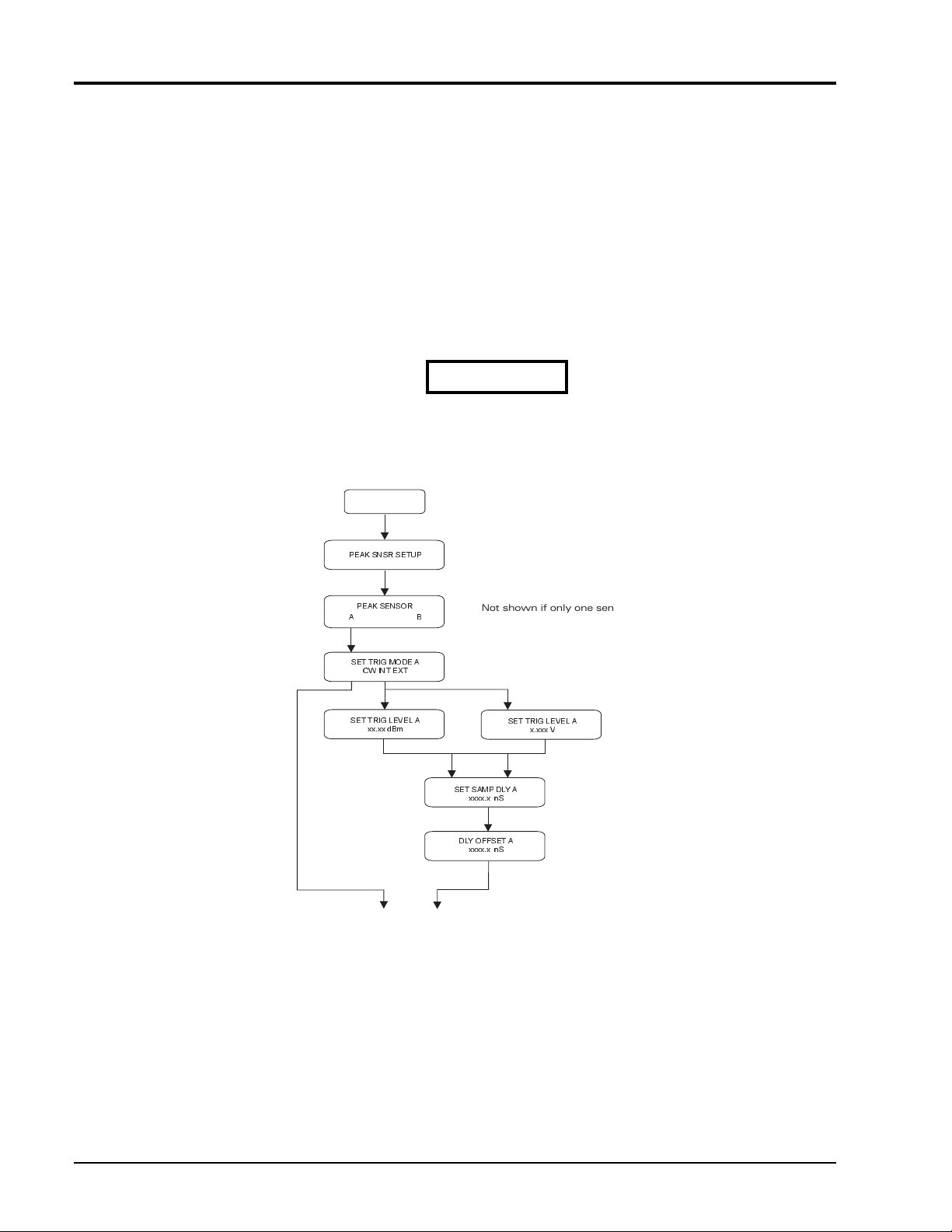
SET UP
PEAK SNSR SETUP
PEAK SENSOR
A
SET TRIG MODE A
CW INT EXT
SET TRIG LEVEL A
xx.xx dBm
To default display
B
Not shown if only one sensor is attached
or if the power meter is single- channel (8541)
SET TRIG LEVEL A
x.xxx V
SET SAMP DLY A
xxxx.x nS
DLY OFFSET A
xxxx.x nS
Figure 2-1: Sensor Setup Menu Tree
2-2 Manual 21568, Rev. F, March 2008

2.2.2 Triggering
The 8540 power meters will not display a new peak power reading until the 8035XA sensor is
triggered. The default configuration is internal triggering (INT) at -20 dBm. Press [MENU],
select SETUP MENU, select PEAK SNSR SETUP, (select sensor A or B if necessary), and then
select INT triggering. You can then enter a new internal trigger level. Be sure that the value is 3
dB or greater below the peak powe r level of the signal being measured. If you are attemptin g to
trigger at excessively low power levels, measurement repeatability and noise performance can
be improved by using external (EXT) triggering.
INT Trigger Level
Operation
Amplitude Profile of
Meaured Signal.
Figure 2-2: Internal Triggering Levels
Manual 21568, Rev. F, March 2008

Series 8035XA Peak Power Sensors
This is a pproximately 0.0 ns delay.
A built in delay line provides at least
20 ns look-ahead capability.
Sample Delay Pulse
10 sµ
Delay
58542 VXIbus Power Meter SCPI Compatible Commands
OUTPUT @Pwr_MTR;SENS1:TRIG:SOUR INT
OUTPUT @Pwr_mtr, SENS1: TRIG: DEL 10E-06
WAIT 200
OUTPUT @Pwr_mtr, MEAS1?
ENTER @Pwr_mtr: Peak_pwr_rdg
! Selects Internal Triggering
! Sets Sample Delay Position to 10 s
! Wait 200 ms for Sample Time Set
! Take a Measurement
µ
RF
Envelope
Trigger Level
(Int. or Ext.)
2.2.3 Zeroing
Zero the sensor before taking critical measurements in the bottom 10 dB of the peak power
sensor’s dynamic range. For standard peak power sensors, this level is -10 dBm.
When making dual channel power measurements, zero the sensors whenever another sensor
is attached or disconnected. Use the following steps:
1. Turn off the RF source.
2. Press [CAL/ZERO].
The sensors will zero automatically. The 8540 power meters detect when a sensor is attached
to the calibrator port. When a sensor is not attached to the power sweep calibrato r, the power
meter automatically initiates the zeroing procedure (if only one sensor is connected to the
meter). Be sure to deactivate the RF source for zeroing. Leaving the sensor attached to your
measurement test ports during zeroing properly accounts for test setup ground noise an d metal
to metal contact thermal EMF.
The 8035XA Series EXT trigger port is on the back of the sensor , not the power meter. A set of
three SMB(f) to BNC(m) cables are included with each 80 35XA Series senso r. The EXT tr igger
input impedance is 110 kΩ. This allows you to use TTL level signals without damaging the inp ut
circuit. However, the input impedance match might cause triggering line reflections and
potential false triggering when fast (50 Ω) trigger sources are used.
This can be resolved by setting the EXT trigger level (see Figure 2- 1).
The CW power measurement mode is also selected in the Peak Sensor Setup menu. CW
measurements are automatica lly performed on a continuous basis.
2-4 Manual 21568, Rev. F, March 2008
Figure 2-3: 8035XA Sensor Timing Diagram

2.2.4 Sensor Triggering
A measurement will not be possible until the peak power sensor is triggered. The Series 8540
Power Meters will display
verification technique is valid for both Series 8540 and 58542 VXI Power Meters:
1. If you need to verify triggering, connect the Sample Delay output on the back of the
8035XA Series sensor to an oscilloscope using one of the SMB(plug) to BNC(m)
cables provided with the sensor. Set the scope channel to dc coupling, 1.0 µs per
division. Use rising edge (Normal) triggering at about 0.5 V trig ger level. Set the sens or
sample delay to 2.0 µs.
2. The sample delay pulse will appear each time the sensor is triggered. If a pulse does
not appear on the scope display, the sensor is not triggering. Check the triggering
configuration and adjust it if necessary. An analog oscilloscope may show a dim trace
when the repetition rate is low.
3. A quick check that can be made on the 8540 power meter for triggering without using
an oscilloscope is to press [dB/mW] twice. This will clear the current reading and
display
NO TRIG until a valid trigger is received.
Operation
NO TRIG until a valid trigger is received. The following trigger
Manual 21568, Rev. F, March 2008
Series 8035XA Peak Power Sensors
2.3 Sample Delay
Sample Delay is the time value in nano-, micro-, or milliseconds that appears on the Series
8540 display after an 8035XA Series sensor has been calibrated. This is the length of time
between the trigger point and the sample point on the pulsed signal. This capability allows you
to measure the power level of your pulsed sig nal at any time point along its amplitude path. The
power level displayed is the true, sampled signal level at the time position that you specified;
the pulse level is not interpolated from two adjacent samples as is com mon in random sampling
oscilloscope-type peak power meters.
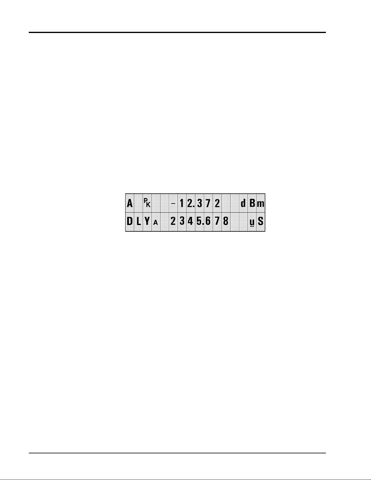
Sample delay is fully adjustable from -20 ns to 100 ms. On the 8541/2 front panel, use the
arrow keys to position the cursor and adjust the time values. Seven digits, four to the left of the
decimal and three to the right of the decimal, can be edited in the microsecond (ns) and
millisecond (ms) ranges (see Figure
allows four digits to the left of the decimal, but only a .0 or .5 to the right of the decimal.
The 0.0 ns time delay setting will be close to the trigger level when internal triggering is used. If
your measurements require definition of the 0.0 ns position, use Sample Delay Offset to adjust
for small triggering variations.
2-4 for an example.) The nanosecond range
Figure 2-4: Sample Delay Adjustment Display
Full 0.5 ns resolution is always possible regardless of the front panel units disp lay. On the
millisecond ranges, small nanosecond level increments in sample delay can be performed by
incrementing Sample Dly Offset in the Peak Sensor Setup menu tree. In addition to allowing
control of small nanosecond range sample delay increments while currently displaying
millisecond ranges, sample delay offsets allow you to compensate for cabling and circuit time
delays in your test setup. The sensor delay is the sum of DLY
and DLY OFFSET
)
B
and DLY OFFSETA (or DLYB
A
2-6 Manual 21568, Rev. F, March 2008
 Loading...