

Giga-tronics 8003 Operation Manual
P/N:
Revision:
Print Date:
20791
June 2001
C
8003 Precision Scalar Analyzer
Operation Manual
8003
ISO 9001
Registrar: BSI, Certification No. FM 34226 ❖ Registered 04 June 1996 ❖ Amended 01 March 2000
Giga-tronics Incorporated ❖ 4650 Norris Canyon Road ❖ San Ramon, California 94583
925.328.4650 or 800.726.4442 ❖ 925.328.4700 (Fax) ❖ 800.444.2878 (Customer Service) ❖ 925.328.4702 (CS Fax)
www.gigatronics.com
..................................................................................................................................... Certified Process

All technical data and specifications in this manual are subject to change without prior notice and do not represent a commitment on
the part of Giga-tronics Incorporated.
© 2001 Giga-tronics Incorporated. All rights reserved.
Printed in the USA.
WARRANTY
Giga-tronics Series 8003 instrument is warranted
against defective materials and workmanship for
one year from date of shipment. Giga-tronics will at
its option repair or replace products that are proven
defective during the warranty period. This warranty
DOES NOT cover damage resulting from improper
use, nor workmanship other than Giga-tronics
service. There is no implied warranty of fitness for
a particular purpose, nor is Giga-tronics liable for
any consequential damages. Specification and
price change privileges are reserved by Gigatronics.
Exclusion of Other Warranties
The Warranty described above is Buyer’s sole and exclusive remedy and no other Warranty, whether written or oral,
is expressed or implied. Giga-tronics specifically disclaims the implied warranties of merchantability and fitness for
a particular purpose. No statement, representing, agreement, or understanding, oral or written, made by an agent,
distributor, representative, or employee of Giga-tronics, which is not contained in the foregoing Warranty will be
binding upon Giga-tronics, unless made in writing and executed by an authorized Giga-tronics employee. Under no
circumstances shall Giga-tronics be liable for any direct, indirect, special, incidental, or consequential damages,
expenses, losses, or delays (including loss of profit) based on contract, tort, or any other legal theory.

IMPORTANT NOTICE
☛☛☛☛
Using Password Protection with the 8003
The Giga-tronics 8003 Precision Scalar Analyzer is shipped from the factory with the password protection feature OFF.
Password protection can be user activated to prevent unauthorized changes in the Cal Factor and Calibrator data stored
in the EEPROMs in the 8003 and sensors used with the instrument. It is strongly recommended that this password
protection be implemented immediately to prevent any problems that could arise due to accidental or unintentional
changes to the calibration data stored in the EEPROMs. Use the following procedure to activate the password protection
for the sensors and/or bridge:
1. Since the password is stored directly in the EEPROM physically contained in the housing of each sensor, attach the
sensor(s) to be protected to the A, B and/or C connections on the front panel of the 8003.
☛☛☛☛
2. After the 8003 has been turned on, press the CONFIG key on the front panel.
3. The display will present the primary CONFIG menu. Press the SERVICE softkey at the bottom of the menu.
4. Press the SENSOR EEPROM softkey of the next menu presented.
5. A menu will then be displayed showing a choice of sensors A, B or C. Each sensor must be individually password
6. Assuming that sensors are attached to all 3 inputs, press the SENSOR A EEPROM softkey. (If sensors are not
7. Press the PA S S WD softkey of the next menu presented, and then press the DEFINE PASSWD softkey of the menu
8. After the DEFINE PASSWD softkey has been pressed. a prompt will be displayed asking for a password. Six
9. Once the six number keys have been pressed, the display will again present a prompt asking that the password just
10. Then press RETURN and PROGRAM EEPROM to store the password in the sensor EEPROM. From this point on,
11. Start with Step 6 for the next sensor to be protected.
For further information on accessing the softkeys used to store a password in the sensor EEPROM, see pages 2-64 and
2-65 in the OPERATION chapter (Operation Manual).
1. The following procedure should be used to activate password protection for the calibrator in the 8003.
2. Press the CONFIG key on the front panel, and then press the SERVICE softkey at the bottom of the primary
3. Press the SET CAL softkey at the top of the next menu presented.
The next menu will contain a softkey label called DEFINE PASSWD. The DEFINE PASSWD softkey is used to define a
password that future users will have to enter in order to change the calibrator output. When this softkey is pressed, a
prompt is presented asking for a new password. Six number keys (the selected password sequence) should then be
pressed. The keys being pressed will not be shown on the screen. Once the six number keys have been pressed, the
display will again present a prompt asking that the password just defined be entered again to confirm the password.
When the password is confirmed, the defined password will be enabled.
NOTE: Sensors can be moved from one instrument to another, and will still retain their password
protection.
protected. Either the same or different passwords can be used for each individual sensor.
connected to all 3 inputs, repeat the procedure that follows for just the sensors being used.)
that follows.
number keys (the selected password sequence) should then be pressed. These keys will not be shown on the
screen.
defined be entered again for confirmation. When the password has been confirmed, the defined password will then
be accepted.
the password must be entered before any calibration data can be changed in the sensor EEPROM.
CONFIG menu.
NOTE: Jumper W1 on the Calibrator Board must be moved to pins 2 and 3 from pins 1 and 2 to complete
the enabling of password protection.
(The CLEAR PASSWD softkey in the same menu as above is used to clear the password. Once this softkey is pressed,
the password will be cleared and future users will be able to adjust the calibrator output without having to know a
password until one is assigned again).
Further information on accessing the softkeys used in setting the calibrator output is given on page 2-61 in the
OPERATION chapter (Operation Manual).

About This Manual .......................................................................................................... ix
Conventions ..................................................................................................................... xi
Record of Manual Changes ............................................................................................ xiii
Special Configurations ..................................................................................................... xv
1
Introduction
1.1 Description....................................................................................................1-1
1.2 Installation ....................................................................................................1-2
Contents
1.1.1 Features .......................................................................................1-1
1.2.1 Safety Precautions ........................................................................1-2
1.2.1.1 Power Input, Fuse & Voltage Selector ............................ 1-3
1.2.2 Line Voltage & Fuse Selection .......................................................1-3
1.2.2.1 Power Sensors............................................................... 1-3
1.2.2.2 Power Sensors Accessories ........................................... 1-3
1.2.3 Power Sensor Precautions ............................................................1-3
1.2.4 Power Requirements ....................................................................1-4
1.2.4.1 Standard Voltage Selector & Fuse Holder....................... 1-5
1.2.4.2 VDE Type Voltage Selector & Fuse Holder...................... 1-5
1.2.5 Environmental Requirements ........................................................1-5
1.2.6 Items Furnished ............................................................................1-5
1.2.7 Items Required .............................................................................1-6
1.2.8 Tools & Test Equipment ...............................................................1-6
1.2.9 Cooling .........................................................................................1-6
1.2.10 Cleaning .......................................................................................1-6
1.2.11 Receiving Inspection .....................................................................1-6
1.2.12 Preparation for Reshipment ..........................................................1-6
1.3 Specifications................................................................................................1-7
1.3.1 Cursors & Markers .......................................................................1-8
1.3.2 Accuracy ......................................................................................1-9
1.4 GPIB Interface .............................................................................................1-13
1.5 Rear Panel Inputs & Outputs.......................................................................1-14
1.5.1 BNC Connectors ......................................................................... 1-14
1.5.2 GPIB Connectors ........................................................................1-14
1.6 Signal Sources ............................................................................................1-15
1.6.1 System Integrated ......................................................................1-15
1.6.2 Operator Integrated ....................................................................1-15
1.6.3 Modulation .................................................................................1-15
1.7 General Specifications .................................................................................1-15
1.3.2.1 Transmission Loss or Gain Measurements..................... 1-9
1.3.2.2 Reflection Measurements............................................. 1-10
1.3.2.3 Absolute Power Measurement Accuracy...................... 1-11
Manual 20791, Rev. C, June 2001 i

8003 Precision Scalar Analyzer
2
Operation
2.1 Introduction...................................................................................................2-1
2.2 Front & Rear Panel Descriptions....................................................................2-1
2.2.1 GPIB Address Selection ................................................................2-7
2.2.2 Display Description .......................................................................2-8
2.3 Softkey Functional Description ....................................................................2-12
2.3.1 Softkey Labels & Color Indications ..............................................2-12
2.3.2 Channel & Function Selection .....................................................2-12
2.3.3 Sensors & Sensor Calibration .....................................................2-12
2.3.4 Absolute Power & Swept Capabilities .........................................2-13
2.3.5 Graph & Readout Display Modes ................................................2-13
2.3.6 Path Calibration Memory ............................................................2-13
2.3.7 Trace Memory ............................................................................2-14
2.3.8 Power On ...................................................................................2-14
2.4 CHANNEL Controls......................................................................................2-15
2.4.1 OFF Key ......................................................................................2-15
2.4.2 DEFINE Key ................................................................................2-15
2.5 FUNCTION Controls.....................................................................................2-18
2.5.1 MEAS Key ..................................................................................2-18
2.5.2 SCALE Key ..................................................................................2-22
2.5.3 DISPLAY Key ..............................................................................2-24
2.5.4 CAL Key ......................................................................................2-36
2.5.5 CURSOR Key ..............................................................................2-40
2.5.6 MEMORY Key .............................................................................2-47
2.6 SOURCE Controls ........................................................................................2-51
2.6.1 General Description ....................................................................2-51
2.6.2 ATE Operation ............................................................................2-51
2.6.3 8003 Source Compatibility ..........................................................2-51
2.6.4 Key Operation .............................................................................2-52
2.6.5 POWER Key ................................................................................2-54
2.6.6 SWEEP TIME Key .......................................................................2-56
2.7 SYSTEM Controls ........................................................................................2-57
2.7.1 PRESET Key ................................................................................2-57
2.7.2 CONFIG Key ................................................................................2-57
2.8 Front Panel Operation..................................................................................2-66
2.8.1 Calibrating for Power Measurement ...........................................2-67
2.8.2 Path Calibration Correction for Component Variations .................2-69
2.8.3 Making a Device Measurement ...................................................2-73
2.9 Insertion & Return Loss Measurements.......................................................2-75
2.9.1 Single-Sensor Insertion Loss Measurement ................................2-75
2.9.2 Two-Sensor Insertion Loss Measurements .................................2-77
2.9.3 Single-Sensor Return Loss Measurements ..................................2-79
2.9.4 Two-Sensor Return Loss Measurements ....................................2-81
2.9.5 Three-Sensor Configurations ......................................................2-82
2.9.6 Trace Memory ............................................................................2-82
2.6.4.1 UPDATE SWEEPER ON/OFF Key .................................. 2-52
2.6.4.2 START Key.................................................................. 2-52
2.6.4.3 STOP Key .................................................................... 2-53
2.8.1.1 Calibration Intervals..................................................... 2-68
2.8.2.1 Set Up Sweep Parameters........................................... 2-69
2.8.2.2 Frequency Response Correction .................................. 2-70
2.9.1.1 Using Channels ........................................................... 2-76
ii Manual 20791, Rev. C, June 2001

Preface
2.10 Scaling the Display...................................................................................... 2-84
2.10.1 Hints on Simplified Scaling .........................................................2-86
2.10.2 Using the Cursor to Set the Reference Level ...............................2-86
2.11 Cursors & Markers ......................................................................................2-87
2.11.1 Search Functions Using the Cursor .............................................2-87
2.11.2 Min & Max Search .....................................................................2-87
2.11.3 Searches on Frequency Selective Devices ................................... 2-89
2.11.4 Bandwidth Searches .................................................................. 2-91
2.11.5 Cursor Delta (
2.11.6 Cursors on Multiple Channels .....................................................2-93
2.11.7 Markers ...................................................................................... 2-94
2.12 Power Measurements .................................................................................2-95
2.12.1 CW Power Measurements ..........................................................2-98
2.12.2 Mixed Mode Measurements ....................................................... 2-98
2.12.3 Cal Factor Corrections in the CW Mode ......................................2-99
2.12.4 Sensor Offsets ..........................................................................2-100
2.12.5 Other CW Functions .................................................................2-100
2.13 Accurate Range Measurements.................................................................2-102
2.13.1 Temperature Stability ...............................................................2-102
2.13.2 Measurement Modes ................................................................2-102
2.13.2.1 CW Mode................................................................... 2-102
2.13.2.2 Swept Mode with AC Detection................................. 2-103
2.13.2.3 Swept Mode with DC Detection................................. 2-103
∆
) Functions ..........................................................2-92
2.14 8003 Power Sweep Measurements...........................................................2-104
3
Remote Operation
3.1 Introduction ..................................................................................................3-1
3.2 IEEE Bus Interface .........................................................................................3-1
3.2.1 Connect the System Controller .....................................................3-1
3.2.2 Set the GPIB Address ...................................................................3-1
3.3 Structured GPIB Language ............................................................................3-7
3.3.1 Common Structure .......................................................................3-7
3.3.2 8003 GPIB Commands .................................................................3-7
3.3.3 Command Execution ..................................................................3-10
3.3.4 IEEE GPIB Interface Characteristics .............................................3-11
3.3.5 Channel Bias Voltage Definition Command Structure ..................3-12
3.3.6 Sensor Calibration Command Structure ......................................3-12
3.3.7 Channel Definition Command Structure ......................................3-13
3.3.8 Cursor Definition Command Structure ........................................3-14
3.3.9 Instrument Preset Command Structure .......................................3-18
3.3.10 Disable Private Bus Command Structure ....................................3-19
3.3.11 Enable Private Bus Command Structure .....................................3-19
3.3.12 External Status Register Query Command Structure ...................3-20
3.3.13 Fixed Frequency Source Mode Definition Command Structure ...3-21
3.3.14 Graph Display Definition Command Structure ............................. 3-23
3.3.15 Instrument Identifier Command Structure ................................... 3-23
3.3.16 Input Command Structure ..........................................................3-24
3.3.17 Key Stroke Emulation Enable/Disable Command Structure ..........3-25
3.3.18 Memory Command Structure .....................................................3-29
3.3.19 Measurement Query Command Structure ..................................3-30
3.3.20 Plot Command Structure ............................................................3-33
3.2.2.1 Programming the 8003 .................................................. 3-2
3.3.3.1
3.3.3.2
3.3.3.3
3.3.3.4 EOL Definition.............................................................. 3-10
3.3.3.5 Case Insensitivity ......................................................... 3-10
hs
Definition................................................................. 3-10
ds
Definition................................................................. 3-10
us
Definition................................................................. 3-10
Manual 20791, Rev. C, June 2001 iii

8003 Precision Scalar Analyzer
3.3.21 CW Power Measurement Command Structure ...........................3-36
3.3.22 Temperature & Low Level Offset Update Structure .....................3-49
3.3.23 Print Definition Command Structure ...........................................3-49
3.3.24 Readout Display Definition Command Structure .........................3-50
3.3.25 Sensor Definition Command Structure ........................................3-51
3.3.26 Sensor Short/Open Calibration Command Structure ...................3-53
3.3.27 Swept Measurement Command Structure ..................................3-54
3.3.28 Start/Stop Swept Frequency Source Mode Def. Cmd. Structure . .3-64
3.3.29 Span Swept Frequency Source Mode Def. Cmd. Structure .........3-67
3.3.30 Sensor Path Calibration Command Structure ..............................3-69
3.3.31 Sensor Zeroing Command Structure ...........................................3-70
3.3.32 STATUS MESSAGES ..................................................................3-70
3.3.33 GPIB/PRIVATE Interface ..............................................................3-71
3.3.34 Pass Through Feature .................................................................3-72
3.3.32.1 488.2 Status Byte........................................................ 3-70
3.3.32.2 488.2 External Status .................................................. 3-71
4
Performance Test & Calibration
4.1 General..........................................................................................................4-1
4.2 Calibrator Verification Procedure....................................................................4-3
4.2.1 Calibrator Output Power Reference Level ......................................4-3
4.2.2 Calibrator Frequency Check ..........................................................4-5
4.2.1.1 Procedure...................................................................... 4-3
4.3 Performance Verification Tests ......................................................................4-6
A
Power Sensors
A.1 Introduction.................................................................................................. A-1
A.2 Power Sensor Selection................................................................................ A-1
4.3.1 Equipment Required .....................................................................4-6
4.3.2 Instrument Plus Power Sensor Linearity .......................................4-7
4.3.2.1 Test Description ............................................................ 4-7
4.3.2.2 Setup Parameters.......................................................... 4-8
4.3.2.3 Test Procedure .............................................................. 4-8
4.3.3 Serial Port Check ........................................................................4-10
4.3.4 GPIB/System Port Check .............................................................4-10
4.3.5 GPIB/Private Port Check ..............................................................4-11
4.3.6 Sweep in Connector Check .........................................................4-11
4.3.7 AC Mode Output Connector Check .............................................4-12
4.3.8 Bias Output Connector Check .....................................................4-12
4.3.9 DAC Output Connector Check .....................................................4-13
4.3.10 RGB Video Output Connector Check ...........................................4-13
4.3.11 SUMMARY .................................................................................4-13
A.2.1 Power Sensor Selection Charts ..................................................... A-2
A.2.2 Directional Bridges........................................................................ A-4
iv Manual 20791, Rev. C, June 2001

B
System Configuration
B.1 Introduction ................................................................................................. B-1
B.2 8003 Default Parameters.............................................................................. B-1
B.3 8003 System................................................................................................ B-3
B.3.1 Sensor Installation ........................................................................ B-3
B.3.2 Bridge Installation ......................................................................... B-3
B.3.3 Sweeper Installation ..................................................................... B-4
B.4 Printer Installation ........................................................................................ B-6
B.4.1 PaintJet Color GPIB Cable Interconnections .................................. B-7
B.4.2 ThinkJet GPIB Cable Interconnections........................................... B-7
B.4.3 LaserJet Family RS-232 Cable Interconnections............................ B-8
B.4.4 LaserJet Printer Switch & Jumper Location and Settings.............. B-9
B.5 Plotter GPIB Installation Interconnections & Pen Colors.............................. B-10
B.5.1 HP 7550A ................................................................................... B-10
B.5.2 HP 7440A ................................................................................... B-11
B.5.3 HP 7475A ................................................................................... B-12
B.5.4 HP 7470A .................................................................................. B-13
B.5.5 HP 7090A .................................................................................. B-14
Preface
B.3.3.1 8003 to Sweeper BNC Connections ........................... B-4
B.3.3.2 GPIB Interconnect Cable Connections ........................ B-5
B.4.3.1 RS-232 Electrical Description ..................................... B-8
B.5.1.1 HP 7550A Pen Color Format (8 Pens)....................... B-10
B.5.2.1 HP 7440A Pen Color Format (8 Pens)....................... B-11
B.5.3.1 HP 7475A Pen Color Format (6 Pens)....................... B-12
B.5.4.1 HP 7470A Pen Color Format (2 Pens)....................... B-13
B.5.5.1 HP 7090A Pen Color Format (6 Pens)....................... B-14
Index
B.6 Connecting Analyzer to an Instrument Controller ....................................... B-15
8003 Precision Scalar Analyzer Index .................................................................. Index-1
Manual 20791, Rev. C, June 2001 v

8003 Precision Scalar Analyzer
Illustrations
Figure 1-1: Power Line Connection .........................................................................1-2
Figure 1-2: Operating Voltage Selection..................................................................1-4
Figure 1-3: Uncertainty Due to Instrument Linearity & Zero Set vs. Input Power ....1-9
Figure 1-4: Reflection Uncertainty Relative to Directivity .......................................1-10
Figure 1-5: Reflection Uncertainty Relative to Source Match.................................1-10
Figure 2-1: 8003 Front & Rear Panel Components..................................................2-2
Figure 2-2: Display Screen Information Locations ...................................................2-8
Figure 2-3: Typical Channel Summary Indications ................................................2-10
Figure 2-4: 8003 Front Panel Controls ..................................................................2-12
Figure 2-5: Channel Control Menus Access w/ DEFINE Key ..................................2-17
Figure 2-6: Function Menus Accessed with the MEAS & SCALE Keys..................2-18
Figure 2-7: Function Menus Accessed w/ DISPLAY Key........................................2-26
Figure 2-8: PLOT ALL Function Hardcopy Printout (Typical)..................................2-27
Figure 2-9: PLOT 4 Function Hardcopy Printout....................................................2-28
Figure 2-10: SC P1P2 Function Screen Hardcopy Printout ......................................2-29
Figure 2-11: Function Menus Accessed with the CAL Key......................................2-36
Figure 2-12: Function Menus Accessed with the CURSOR & MEMORY Keys .........2-42
Figure 2-13: Softkey Menu Change from Frequency Change Prompt......................2-52
Figure 2-14: Stop Key Softkey Menu Prompt ..........................................................2-53
Figure 2-15: Power Softkey Menu Prompt..............................................................2-54
Figure 2-16: System Control Menus Accessed with CONFIG Key (Part 1) ...............2-58
Figure 2-17: System Control Menus Accessed with the CONFIG Key (Part 2) .........2-59
Figure 2-18: Analyzer, Sweeper, Sensor & Bridge Interconnection .........................2-66
Figure 2-19: CAL Softkey Menu..............................................................................2-67
Figure 2-20: Sensor CAL Menu...............................................................................2-67
Figure 2-21: Sensor Calibration Display Screen ......................................................2-68
Figure 2-22: New Frequency Parameters Display Screen........................................2-69
Figure 2-23: Autoscaled thru Path Before Path Calibration Display .........................2-70
Figure 2-24: THRU PATH Calibration Menu ............................................................2-71
Figure 2-25: Calibrated Path Display.......................................................................2-72
Figure 2-26: Successful SHORT/OPEN CAL Display w/ Open Attached ...................2-73
Figure 2-27: Device Measurement Plot (Typical Display).........................................2-74
Figure 2-28: Cursor Plot Typical Display .................................................................2-74
Figure 2-29: Swept Source & Power Sensor Only Block Diagram (w/ DUT) ............2-75
Figure 2-30: More Accurate Insertion Loss Ratioi ng Meas. (Back-to-Back Adpts. Improv-
Figure 2-31: Two Sensor Insertion Loss Setup w/ a Power Splitter.........................2-77
Figure 2-32: Two Sensor Insertion Loss using a Directional Coupler.......................2-77
Figure 2-33: Return Loss Setup Using a Bridge ......................................................2-79
Figure 2-34: Return Loss Test Setup Using a Directional Coupler ...........................2-80
Figure 2-35: Two Sensor Return Loss Setup Block Diagram ...................................2-81
Figure 2-36: Three Sensor Configuration Block Diagram.........................................2-82
Figure 2-37: “Golden Standard” Pr ecision 20 dB Attenuator Measurement Using 20 dB
Figure 2-38: Device Gross Characteristics (Filter Skirt) Display ...............................2-84
Figure 2-39: Device Fine Characteristics (Filter Pass Band) Display.........................2-84
Figure 2-40: SCALE Display & Softkey Menu Typical Display .................................2-85
Figure 2-41: REF
Figure 2-42: Typical Measurement (Cursors, Delta Cursors & Markers)..................2-87
Figure 2-43: MAX Search Finds Minimum Return Loss of a Filter (Passband).........2-88
Figure 2-44: MIN Search Finds Max. Insertion Loss Point (20 dB Fixed Attenuator)2-88
Figure 2-45: -3 dB Point (Low Pass Filter) at 3.175 GHz.........................................2-89
Figure 2-46: -30 dB Point (High Pass Filter) ............................................................2-90
Figure 2-47: Automatic Bandwidth Movement (Very Narrow Bandpass Filter) .......2-91
Figure 2-48: Cursor Delta Indicates Relative Level & Frequency (Next Worse Return Loss
Figure 2-49: Cursors (Each Channel) Tied to Same Frequency Help Finding the 1 dB Com-
Figure 2-50: Filter Passband (Tuned Until Amplitude is -0.5 dB at the Marker) .......2-94
Figure 2-51: Sensor Calibration Screen...................................................................2-95
Figure 2-52: Sensor ID Table ..................................................................................2-96
Figure 2-53: Sensor CAL Factor Table.....................................................................2-96
Figure 2-54: 8003 Swept Power Measurements with CAL Factor Correction..........2-97
Figure 2-55: CW Readings (All 3 Sensor Inputs Plus Ratio).....................................2-98
ing Source Match) ..............................................................................2-76
Attenuator Reference..........................................................................2-83
→
CURSOR Function puts Local Maximum Reference Point at the Ref-
erence Point for Easy Scale Factor Expansion.....................................2-86
Point) .................................................................................................2-92
pression Point on an Amplifier............................................................2-93
vi Manual 20791, Rev. C, June 2001

Preface
Figure 2-56: 3 Different Methods (CAL Factor Correction Plus Sensor Offsets) .......2-99
Figure 2-57: Averaging Used to Reduce Noise ......................................................2-100
Figure 2-58: Reference Level & Corresponding Relative Reading...........................2-101
Figure 2-59: Menus & Typical Display (Power Sweep Measurements) .................2-104
Figure 3-1: Location of GPIB/System Connection (Rear Panel).................................3-1
Figure 3-2: GPIB Commands (Front) .......................................................................3-8
Figure 3-3: GPIB Commands (Back)........................................................................3-9
Figure 3-4: Plot Obtained Using More Complex HP Series 300 Prg. Example........3-28
Figure 3-5: Limit Line Display Example ................................................................. 3-63
Figure 4-1: Calibrator Output Test Setup................................................................4-3
Figure 4-2: Power Linearity Test Setup...................................................................4-7
Manual 20791, Rev. C, June 2001 vii

8003 Precision Scalar Analyzer
Tables
Table 3-1: Definition of ASCII Codes................................................................... 3-26
Table 4-1: Test Equipment Required..................................................................... 4-2
Table A-1: Power Sensor Selection Guide ............................................................ A-2
Table A-2: Power Sensor Cal Uncertainties .......................................................... A-3
Table A-3: Directional Bridge Selection Guide ...................................................... A-4
Table B-1: 8003 Default Settings ......................................................................... B-1
viii Manual 20791, Rev. C, June 2001

About This Manual
This operation manual covers the Giga-tronics 8003 Precision Scalar Analyzer:
Preface:
In addition to a comprehensive Table of Contents and general information about the manual, the
Preface also contains a record of changes made to the manual since its publication, and a description
of Special Configurations. If you have ordered a user-specific manual, please refer to page xv for a
description of the special configuration.
Chapters
1 – Introduction:
This chapter provides a brief introduction to the instrument and its performance parameters.
2 – Operation:
This chapter is a guide to the instrument’s front and rear panel keys, display and configuration
menus.
3 – Remote Operation:
This chapter provides how to operate the instrument from a remote location over the General
Purpose Interface Bus (GPIB). All programming codes are presented in this chapter with
various applications to aid you in understanding the operation.
4 – Performance Test & Calibration:
This chapter provides the procedures to verify the performance of the 8003 Precision Scalar
Analyzer.
Appendices
A - Power Sensors:
This appendix provides selection data, specifications, and calibration procedures for power
sensors.
B - System Configuration:
This appendix contains the 8003 default function parameters, it also contains instructions for
common test equipment and the initial 8003 printer installation directions for its ability to
generate displayed data/plot hardcopies.
Index:
A word index of the various elements of the 8003 manual.
Changes that occur after publication of the manual, and Special Configuration data will be inserted as
loose pages in the manual binder. Please insert and/or replace the indicated pages as detailed in the
Technical Publication Change Instructions included with new and replacement pages.
Manual 20791, Rev. C, June 2001 ix

8003 Precision Scalar Analyzer
x Manual 20791, Rev. C, June 2001

Conventions
The following conventions are used in this product manual. Additional conventions not included here
will be defined at the time of usage.
Warning
WARNINGWARNING
The WARNING statement is encased in gray and centered in the
page. This calls attention to a situation, or an operating or
maintenance procedure, or practice, which if not strictly corrected
or observed, could result in injury or death of personnel. An
example is the proximity of high voltage.
Caution
CAUTION
Notes
☛☛☛☛
The CAUTION statement is enclosed with single lines and centered
in the page. This calls attention to a situation, or an operating or
maintenance procedure, or practice, which if not strictly corrected
or observed, could result in temporary or permanent damage to the
equipment, or loss of effectiveness.
NOTE: A NOTE Highlights or amplifies an essential operating or maintenance procedure,
practice, condition or statement.
Manual 20791, Rev. C, June 2001 xi

8003 Precision Scalar Analyzer
xii Manual 20791, Rev. C, June 2001

Record of Manual Changes
This table is provided for your convenience to maintain a permanent record of manual change data.
Corrected replacement pages will be issued as Technical Publication Change Instructions, and will be
inserted at the front of the binder. Remove the corresponding old pages, insert the new pages, and
record the changes here.
Change
Instruction
Number
Change
Instruc tion
Date
Date
Entered Comments
Manual 20791, Rev. C, June 2001 xiii

8003 Precision Scalar Analyzer
xiv Manual 20791, Rev. C, June 2001

Special Configurations
When the accompanying product has been configured for user-specific application(s), supplemental
pages will be inserted at the front of the manual binder. Remove the indicated page(s) and replace it
(them) with the furnished Special Configuration supplemental page(s).
Manual 20791, Rev. C, June 2001 xv

8003 Precision Scalar Analyzer
xvi Manual 20791, Rev. C, June 2001

1.1 Description
The 8003 Precision Scalar Analyzer measures scalar (magnitude only) properties of microwave
components. These properties include insertion characteristics (gain or attenuation) and reflection
characteristics (return loss or VSWR). The 8003 offers a 90 dB dynamic range with a linearity of
±
0.04 dB in the CW Mode and ±0.06 dB in the Swept Mode.
A unique feature of the 8003 is its ability to make CW power meter-accurate power measurements.
Giga-tronics power sensors include EEPROMs programmed with Cal Factor data to give fully corrected
power readings during frequency sweeps. A front panel calibrator linearizes sensors and bridges to
±
0.04 dB linearity, and provides an absolute power accuracy of ±0.7% at 1 mW. In essence, the 8003
can be used as an accurate 3-channel power meter.
1.1.1 Features
• Large full color display for easy viewing of traces and quick identification of channels
1
Introduction
• Built-in sweeper control for automated setups and easier control of complex measurements
• Expert system menus that use color to help the operator quickly learn instrument operation
• Non-volatile memory to store functions such as path calibrations, user selected traces, and
instrument states
• Full CW meter functionality including a large digital display mode, plus capabilities for including
offsets, max and min hold, averaging, and ratio or difference measurements
• Full plot compatibility with most GPIB plotters and HP Laserjet series printers
• Fast CW Mode option over the GPIB
• Use with Triggerable Pulse (Peak Power) Sensors for swept peak measurements
Manual 20791, Rev. C, June 2001 1-1
8003 Precision Scalar Analyzer
1.2 Installation
The analyzer can be placed directly on a work bench or mounted in a 24-inch deep equipment rack by
using the optional Y6001 or Y6002 Rack Mount Kit. Instructions for installing the 8003 with Rack
Mount Kit are provided in the kit.
Allow at least 3-inches of clearance behind and on each side of the instrument for proper air circulation.
The following installation procedures must be completed before
turning the instrument on for the first time, and whenever it is relocated or installed into a different system.
Select the correct operating voltage and install the proper fuse in this housing. Refer to Section 1.2.2,
Line Voltage and Fuse Selection for instructions on how to select the voltage and replace the fuse.
Observe the following Safety Precautions when installing the 8003. See Section 1.5 for connecting to
the rear panel.
CAUTION
Do not connect main power to the unit until you have checked the
required operating voltage and fuse rating. The instrument can be
damaged if connected to a source voltage with the line voltage selector set incorrectly.
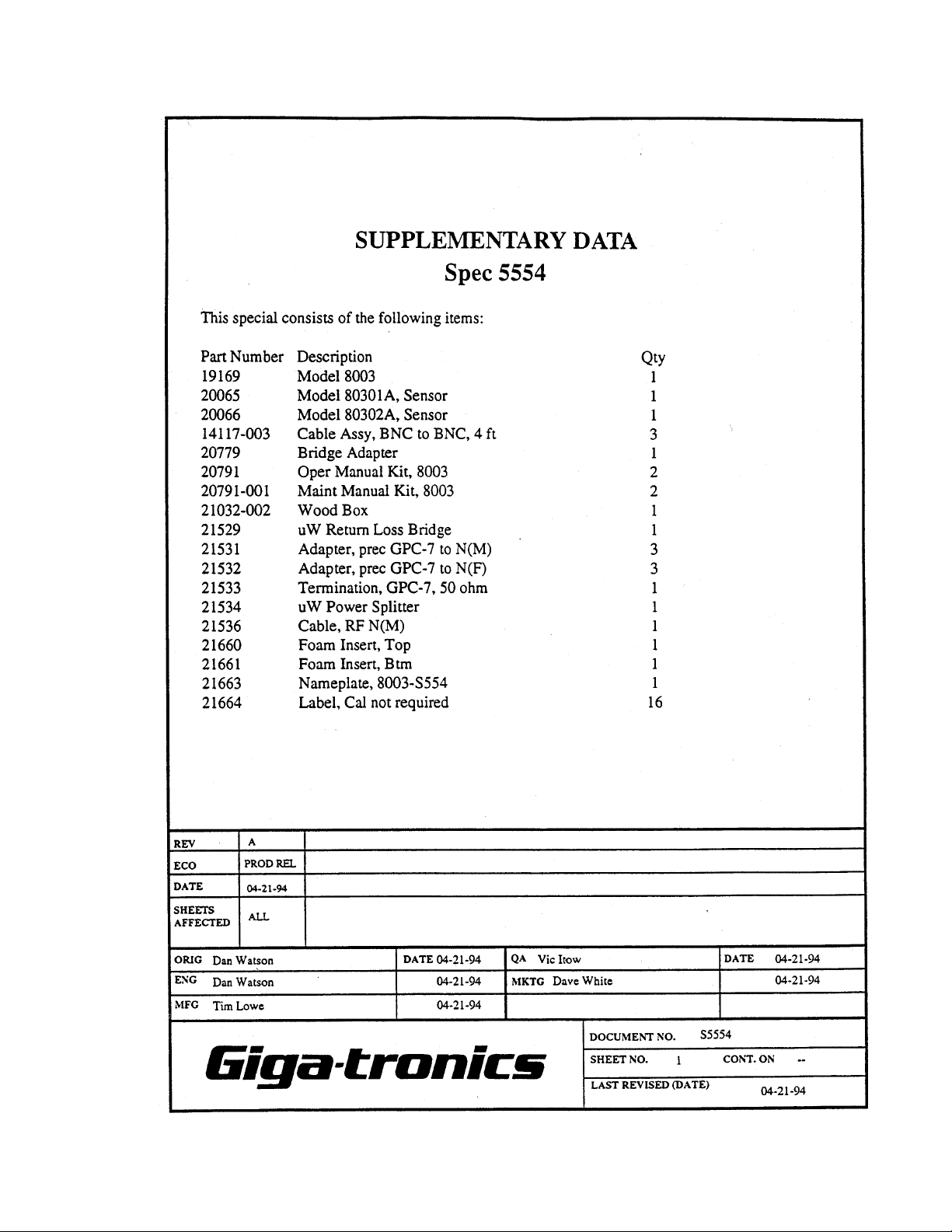
1.2.1 Safety Precautions
This 8003 has a 3-wire power cord with a 3-terminal polarized plug for connection to the power source
and safety-ground. The ground (or safety ground) is connected directly to the chassis.
If a 3-to-2 wire adapter is used, connect the ground lead from the
adapter to earth ground. Failure to do this can cause the instrument to float above earth ground, posing a shock hazard.
EARTH GROUND
CAUTION
WARNING
LINE
NEUTRAL
LINE
NEUTRAL
EARTH GROUND
Figure 1-1: Power Line Connection
1-2 Manual 20791, Rev. C, June 2001

The 8003 is designed for international use with source voltages of 100, 120, 220, or 240 Vac, ±10% at
48 to 440 Hz. The 8003 uses an internationally approved connector that includes voltage selection, fuse,
and filter for RFI protection.
1.2.1.1 Power Input, Fuse & Voltage Selector
The input voltage must be set to match the source at the location where the instrument is to be used.
The number visible through the window on the selector card is the nominal line voltage to which the
analyzer must be connected. See Section 1.2.4 for the power and fuse requirements, and procedures to
select the voltage and to change the fuse.
CAUTION
Do not connect the ac power cord until you have confirmed that the
input voltage has been properly selected and that the fuse for the ac
input is correct.
1.2.2 Line Voltage & Fuse Selection
The instrument is shipped in an operational condition and no special installation procedures are
required except to check and/or set the operating voltage and fuse selection as described in the
following.
Introduction
1.2.2.1 Power Sensors
The 8003 Series of Power Sensors are designed specifically for use with the 8003. The same sensors are
used for both swept measurements and CW measurements. Both AC and DC detection modes can be
used with any of the power sensors with the exception of the 80340 Series. Each sensor includes an
EEPROM which has been programmed with Calibration Factor data for that specific sensor. General
specifications for each sensor and calibration factor uncertainties are detailed in Appendix A.
1.2.2.2 Power Sensors Accessories
Each 8003 instrument is shipped with an adapter to interface power sensors with APC3.5(m) and
Type K (m) connectors to the Type N (m) connector of the 8003’s front panel Calibrator output.
Adapters for sensors with APC7 connectors are optionally available.
1.2.3 Power Sensor Precautions
Power sensor safety precautions, selection, specifications, and calibration are detailed in Appendix A of
this manual.
Manual 20791, Rev. C, June 2001 1-3
8003 Precision Scalar Analyzer
1.2.4 Power Requirements
100/120/220/240 Vac ±10%, 48-440 Hz, 200 VA, typical.
The instrument is supplied with a three-conductor NEMA type power cord. For 100/120 Vac operation,
the neutral conductor is white and the hot wire is black. For 200/240 Vac operation, both the white and
black wires are hot. The green wire of the power cord is for connection to earth ground. The instrument
will be properly grounded if the plug is connected to a properly installed three-prong receptacle. If a
three-prong to two-prong adapter is used, be sure that the pigtail lead of the adapter is earth-grounded.
The safety ground is connected directly to the chassis. If a 3-to-2
wire adapter is to be used, be sure to connect the ground lead
from the adapter to earth ground. Failure to do this could cause
the instrument to float above ground, posing a shock hazard to
personnel.
The line voltages and fuse ratings are:
WARNING
Line Voltage
Fuse Rating
100/120 Vac, ±10%, 50, 60 or 400 Hz 3.0 AMP
±
220/240 Vac,
10%, 50, 60 or 400 Hz 1.5 AMP
CAUTION
Verify that the voltage setting and line fuse in the 8003 match the
ac power source at your facility before connecting the line power
cord.
The unit is set at the factory for operation at the normal supply voltage for the country in which it is
±
sold. The input frequency must be 50, 60, or 400 Hz
transformer design allows instrument operation of 100/120 Vac (using a 3 Amp Slo-Blo fuse) or
220/240 Vac (using a 1.5 Amp Slo-Blo fuse), with an average power consumption of 100 VA.
Conversion from one voltage to another can be made by changing the voltage selection PC board.
5%. The combination of the module and
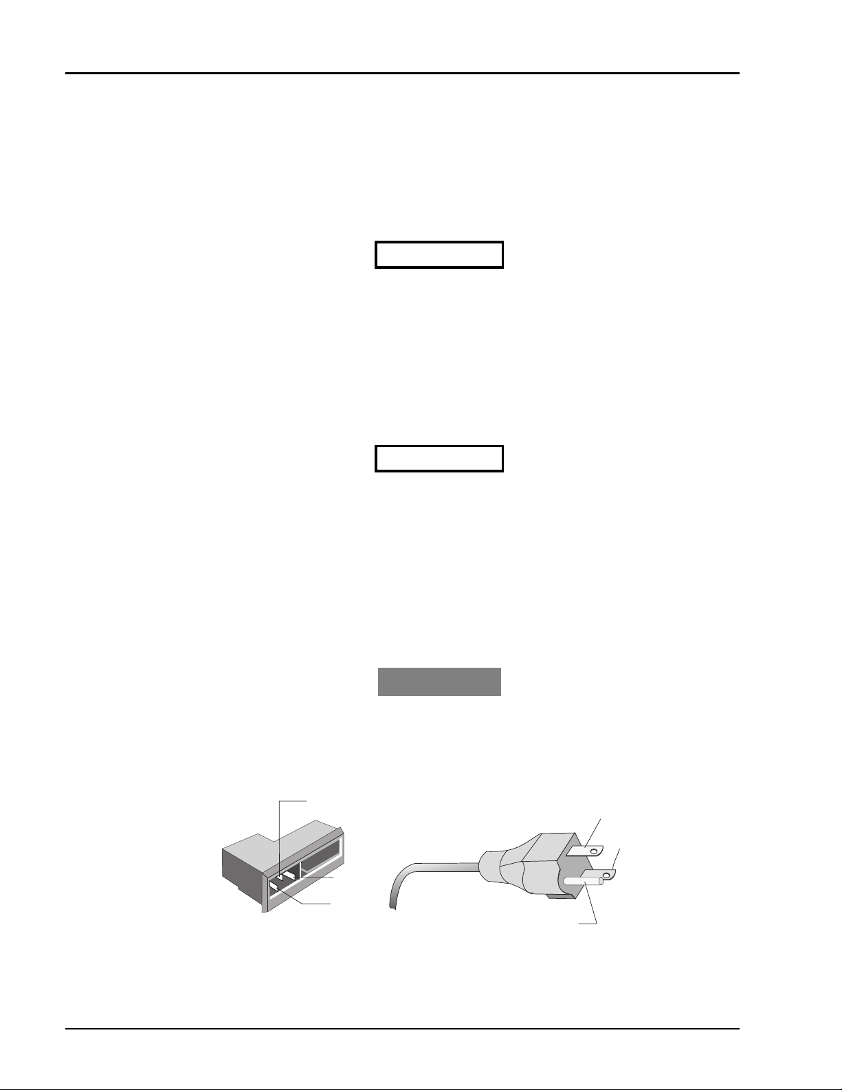
Operating voltage is shown
in the module window
Figure 1-2: Operating Voltage Selection
1-4 Manual 20791, Rev. C, June 2001

Introduction
To select a different operating line voltage and fuse, refer to Figure 1-2 and proceed as follows:
☛☛☛☛
1.2.4.1 Standard Voltage Selector & Fuse Holder
1. Open the cover door, rotate the fuse-pull to the left, and remove the fuse.
2. Select the operating voltage by orienting the PC board so that the correct voltage label is on the
3. Push the board firmly back into the module slot.
4. Rotate the fuse-pull back into the normal position and reinsert the fuse into the holder. Use care to
1.2.4.2 VDE Type Voltage Selector & Fuse Holder
1. Open the cover using a small screwdriver or similar tool and proceed as follows:
2. Use the same tool to remove the voltage selector (a small barrel-shaped component marked with
NOTE:
below, or the VDE-type fuse holder described in Section 1.2.4.2. Refer to the appropriate
instructions for your analyzer.
top left side.
select the correct fuse value.
voltage settings). Rotate the selector so that the desired voltage faces outward and place the selector
back in its slot. Close the housing cover; the appropriate voltage should be visible through the
window (see Figure 1-2).
The analyzer may be furnished with the voltage selector and fuse holder described
3. With the housing cover open, pull out the small drawer on the right side of the housing (it’s marked
with an arrow) and remove the old fuse. Replace with a new fuse, insert the drawer and close the
housing cover (see Figure 1-2).
1.2.5 Environmental Requirements
The 8003A instrument is type tested as follows:
• Operating temperature range is 0°C to 50°C (calibrator operating temperature range is
5°C to 35°C
• Non-operating (storage) temperature range is -40°C to +70°C
• Relative humidity is limited to 95% non-condensing
1.2.6 Items Furnished
In addition to options and/or accessories specifically ordered, items furnished with the instrument are:
• 1 ea. - Power Cord
• 1 ea. - Model 8003 Network Analyzer & CW Power Meter
• 1 ea. - Operation Manual (P/N 20791)
• 3 Detachable sensor/bridge cables each (5 feet long)
Manual 20791, Rev. C, June 2001 1-5

8003 Precision Scalar Analyzer
1.2.7 Items Required
The 8003 requires an external power sensor; see Appendix A for Power Sensor Specifications.
1.2.8 Tools & Test Equipment
No special tools are required to operate the 8003.
1.2.9 Cooling
No cooling is required if the instrument is operated within its specified operating temperature range
(0 to 50°C).
1.2.10 Cleaning
The front panel can be cleaned using a cloth dampened with a mild detergent; wipe off the detergent
residue with a damp cloth and dry with a dry cloth. Solvents and abrasive cleaners should not be used.
1.2.11 Receiving Inspection
Use care in removing the instrument from the carton and check immediately for physical damage, such
as bent or broken connectors on the front and rear panels, dents or scratches on the panels, broken
extractor handles, etc. Check the shipping carton for evidence of physical damage and immediately
report any damage to the shipping carrier.
Each Giga-tronics instrument must pass rigorous inspections and tests prior to shipment. Upon receipt,
its performance should be verified to ensure that operation has not been impaired during shipment.
Follow the installation instructions in Section 1.2 and the operating instructions in Chapters 2 or 3.
1.2.12 Preparation for Reshipment
Follow these instructions if it is necessary to return the product to the factory.
To protect the instrument during reshipment, use the best packaging materials available. If possible use
the original shipping container. If this is not possible, a strong carton or a wooden box should be used
Wrap the instrument in heavy paper or plastic before placing it in the shipping container. Completely
fill the areas on all sides of the instrument with packaging material. Take extra precautions to protect
the front and rear panels.
Seal the package with strong tape or metal bands. Mark the outside of the package
DELICATE INSTRUMENT”
regarding reshipment, please reference the full model number and serial number. If the instrument is
being reshipped for repair, enclose all available pertinent data regarding the problem that has been
found.
NOTE:
☛☛☛☛
Customer Service so that a return authorization number (RMA) can be assigned via e-mail
at repairs@gigatronics.com or at 800.444.2878 (The 800 number is only valid within the
US). You may also try our domestic line at 925.328.4650 or Fax at 925.328.4702.
If you are returning an instrument to Giga-tronics for service, first contact
. If corresponding with the factory or local Giga-tronics sales office
“FRAGILE —
1-6 Manual 20791, Rev. C, June 2001

1.3 Specifications
The following are the specifications for the 8003.
System
Introduction
Frequency Range: 10 MHz to 40 GHz in coax using Giga-tronics 803XXA Series power
sensors and 80500 Series bridges and an appropriate sweeper (see
the signal sources in Appendix A)
Power Range: +30 to -70 dBm (see the Power Sensor specifications in Appendix A)
System Dynamic Range
CW Measurements: 90 dB
Swept Measurements: AC Mode: 90 dB
DC Mode: 80 dB
Peak Measurements: 40 dB
Inputs: Three identical inputs, A, B and C accept detected outputs from
Giga-tronics power sensors and bridges.
Display
CRT: Full color display. Each channel can be assigned a different color.
Display Resolution: 608 x 430 points for each channel.
Channels: Four channels can be used to select and simultaneously display up to
Graticule is selectable (default is green). Menus for the softkeys use
color.
three inputs from A, B and C in single channel or ratio mode.
Graph/Readout Mode
Graph Mode
Log: dBm: Single channel power measurement.
Readout Mode
Log: dBm: Single channel power measurement.
Linear: nW,
Graph mode displays swept frequency response on the CRT. The
Readout mode displays the power level at the cursor frequency or
CW power levels in digital format on the CRT.
dB: Relative power measurement (ratio or relative to the trace
memory).
dB: Relative power measurement.
µ
W, mW, and Watts: Single channel measurement
%: Dual channel measurement.
% Rel: Dual channel measurement relative to a device.
Display
Mode
dBm/dB 0.1 to 20 dB/Div
Display Scale
Resolution
(1, 2, 5 sequence)
Display Range
-99.99 to +99.99 dBm 0.01 dB
Ver tical
Resolution
Manual 20791, Rev. C, June 2001 1-7

8003 Precision Scalar Analyzer
Channel Offset: -90 to +90 dB in .01 dB increments.
Autoscale: Automatically sets the scale factor, reference level, and reference
Averaging: 2, 4, 8, 16, 32, 64, 128, or 256 successive traces (swept) or readings
Smoothing: Provides a linear moving average of adjacent data points. The
Adaptive Path Calibration
(Normalization): Traces are stored in non-volatile memory and normalized with the
Trace Memory: Ten traces can be stored in non-volatile memory and recalled.
Settings Store and Recall: Allows up to nine full front panel setups plus a power-down last
Limit Lines: Horizontal, sloped, and/or single point lines for each trace can be set
position to provide an optimum display of the active channel.
(CW) can be averaged to reduce the effects of noise on
measurements.
smoothing aperture defines the trace width (number of data points) to
be averaged. The smoothing aperture can be set from 0.1% to 20%
of the trace width.
highest resolution, independent of display scale/division or offset.
4096 points for each trace are stored over the full frequency range of
the sweeper or any user-selected frequency range. Normalization
data is automatically interpolated for ranges within the original
normalized range.
Memory traces can be individually labeled. Stored traces can be
displayed, and trace differences from any measurement can also be
displayed.
instrument state can be stored and recalled from non-volatile
memory.
as go/no-go data limits. Limit lines are stored in non-volatile memory.
Complex limit lines can be entered through the front panel or via
GPIB interface.
1.3.1 Cursors & Markers
Cursor: The cursor can be positioned with the tuning or via the numeric
Cursor Delta: Displays the differences in dB and frequency between the reference
Cursor Min/Max: Moves the cursor to the minimum or maximum value of test data.
Cursor x dB: Moves the cursor to the point on the trace equal to the value of x in
Cursor x Bandwidth: Displays cursors to the right and left of the cursor at the frequencies
Cursor Flatness: Displays the difference in dB between the Max and Min values on the
Ref to Cursor: Changes the Ref Level to the level at the cursor.
Markers: Displays up to 10 markers generated by the 8003. The cursor can be
keypad. The frequency and amplitude of test data at the cursor on all
active channels is digitally displayed.
cursor and the main cursor.
dB or dBm.
where the test data is equal to the value of x dB. The bandwidth
between the cursors is displayed.
active channel.
moved directly to any marker or sequentially through the markers.
1-8 Manual 20791, Rev. C, June 2001
1.3.2 Accuracy
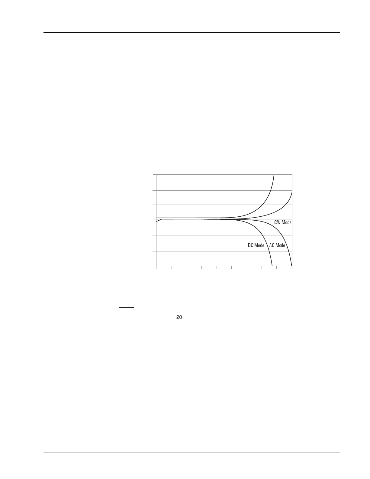
1.3.2.1 Transmission Loss or Gain Measurements
Transmission loss or gain measurements are made relative to a 0 dB reference point established during
calibration. Therefore, frequency response errors of the source, sensors, and signal splitting device are
removed. The remaining elements of uncertainty are instrument linearity and zero set uncertainty, see
Figure 1-3, and mismatch error.
Transmission Accuracy = Instrument Accuracy + Mismatch Uncertainty
The low VSWR 8031XA series of sensors and the high power 8032XA series sensors have built-in
attenuators. Therefore, the linearity at a particular power level must be modified to apply to the
unattenuated sensor. Thus, for the 8031XA series which have a 6 dB attenuator, the linearity
specifications will be for 6 dB more power than in the basic 8030XA Series of sensors. This is reflected
in the scaling at the bottom of Figure 1-3.
3
2
Introduction
1
0
-1
Maximum Error (dB)
-2
-3
Sensor
80301A
80310A
80320A
80330A
Bridge
80501
Figure 1-3: Uncertainty Due to Instrument Linearity & Zero Set vs. Input Power
20
26
30
10
16
20
20
10
15
0
-10
6
-20
-4
-14
0
-10
20
-5
5
Power (dBm)
-30
-24
-20
10
-15
-40
-34
-30
0
-25
-50
-44
-40
-10
-35
CW Mode
AC ModeDC Mode
-60
-54
-50
-20
-45
70
-64
-60
-30
-55
Manual 20791, Rev. C, June 2001 1-9
8003 Precision Scalar Analyzer
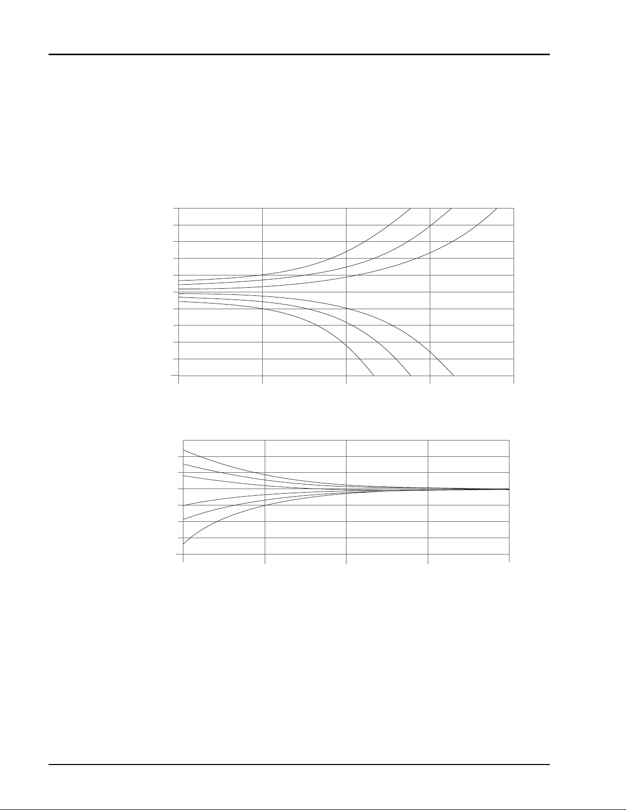
1.3.2.2 Reflection Measurements
When measuring devices with high return loss (>10 dB), reflection accuracy is typically dominated by
the effective system directivity, instrument linearity errors, and noise uncertainty. With low return loss
devices (<10 dB), reflection accuracy is typically dominated by source match. Calibration with an open
and short effectively removes uncertainties due to frequency response of the source, sensors, and signal
splitting device.
Reflection Accuracy = Scalar Accuracy+ Reflection Bridge Accuracy
5
4
3
2
Directivity = 30 dB
Directivity = 35 dB
Directivity = 40 dB
1
0
-1
-2
Maximum Error (dB)
-3
-4
Directivity = 30 dB
Directivity = 35 dB
Directivity = 40 dB
-5
010203040
Figure 1-4: Reflection Uncertainty Relative to Directivity
VSWR = 2
2
VSWR = 1.5
1
VSWR = 1.25
0
-1
VSWR = 1.25
-2
VSWR = 1.5
-3
-4
VSWR = 2
Maximum Error (dB)
0
10 20 30 40
DUT Return Loss (dB)
Figure 1-5: Reflection Uncertainty Relative to Source Match
1-10 Manual 20791, Rev. C, June 2001
 Loading...