

Giga-tronics 3000-08 90400490-100, 3000-08 90400490-105, 3000-08 90400490-102, 3000-08 90400490-106, 3000-09 90400230 Operation Manual
Page 1
Manual 07507588 Model 3000-08,-09
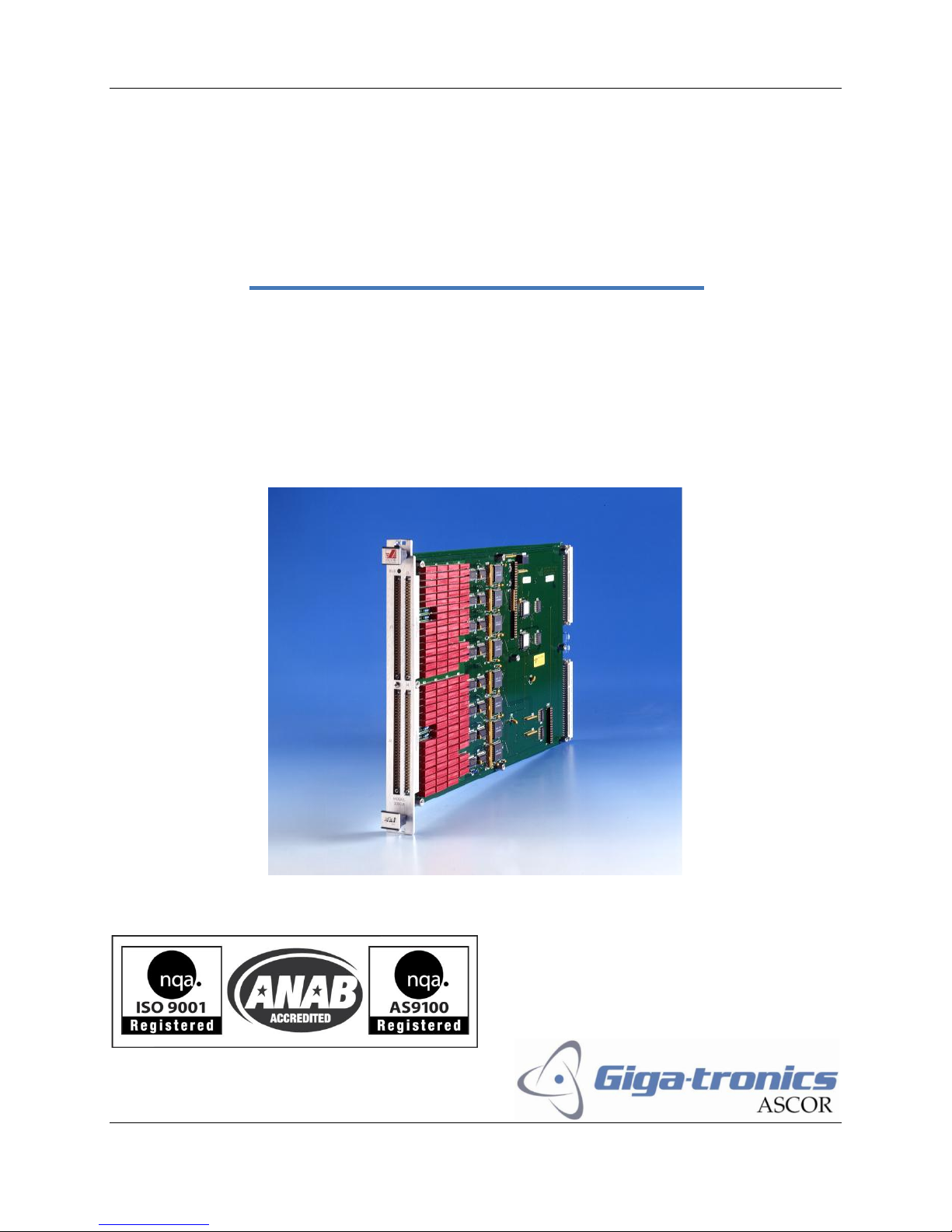
Model 3000-08
8(1x30) Multiplexers
90400490-100, -102, -105, -106
Model 3000-09
16(1x30) Multiplexers
90400230
Page 1 Operation Manual
Page 2

Manual 07507588 Model 3000-08,-09
Warranty
Giga-tronics Series 3000 Switching Modules are warranted against
defective materials and workmanship for three years from date of shipment,
or as detailed in the warranty section of this manual. Giga-tronics will, at its
option, repair or replace products that are proven defective during the
warranty period. This warranty DOES NOT cover damage resulting from
improper use, nor workmanship other than Giga-tronics service. There is no
implied warranty of fitness for a particular purpose, nor is Giga-tronics liable
for any consequential damages. Specification and price change privileges are
reserved by Giga-tronics.
All technical data and specifications in this publication are subject to change without prior notice and do
not represent a commitment on the part of Giga-tronics, Incorporated.
© 2011 Giga-tronics Incorporated. All rights reserved. Printed in the U.S.A.
CONTACT INFORMATION
Giga-tronics, Incorporated
4650 Norris Canyon Road
San Ramon, California 94583
Telephone: 800.726.4442 (only within the United States)
925.328.4650
Fax: 925.328.4700
On the Internet: www.gigatronics.com
Page 2 Operation Manual
Page 3

Manual 07507588 Model 3000-08,-09
89/336/EEC and 73/23/EEC
EMC Directive and Low Voltage Directive
EN61010-1 (1993)
Electrical Safety
EN61326-1 (1997)
EMC – Emissions and Immunity
Manufacturer’s Name:
Manufacturer’s Address
Giga-tronics, Incorporated
4650 Norris Canyon Road
San Ramon, California 94583
U.S.A.
Type of Equipment:
Model Series Number
Switching Module
3000-08
Regulatory compliance information
This product complies with the essential requirements of the following applicable European
Directives, and carries the CE mark accordingly.
Declaration of Conformity on file. Contact Giga-tronics at the following;
Giga-tronics, Incorporated
4650 Norris Canyon Road
San Ramon, California 94583
Telephone: 800.726.4442 (only within the United States)
925.328.4650
Fax: 925.328.4700
Page 3 Operation Manual
Page 4

Manual 07507588 Model 3000-08,-09
TPCI
Number
TPCI Issue
Date
Date Entered
Comments
Record of Changes to This Manual
Use the table below to maintain a permanent record of changes to this document. Corrected
replacement pages are issued as Technical Publication Change Instructions (TPCI). When you
are issued a TPCI, do the following:
1. Insert the TPCI at the front of the manual binder.
2. Remove the pages from the manual binder that are noted in the TPCI.
3. Replace the page(s) removed in the previous step with the corrected page(s).
4. Record the changes in the table below.
Page 4 Operation Manual
Page 5

Manual 07507588 Model 3000-08,-09
Revision History
Revision
Description of Change
Chg Order #
Approved By
A
Initial Release 12/05
B
Updated 9/11
C
Reformatted 2/12
RCW
Page 5 Operation Manual
Page 6

Manual 07507588 Model 3000-08,-09
Contents
Contents ........................................................................................................................................................ 6
Chapter 1 Introduction ................................................................................................................................. 7
1.1 Safety and Manual Conventions ......................................................................................................... 7
1.1.1 Product Reference ....................................................................................................................... 7
1.1.2 Personal Safety Alert ................................................................................................................... 7
1.1.3 Equipment Safety Alert ............................................................................................................... 7
1.1.4 Notes ........................................................................................................................................... 7
1.1.5 Electrical Safety Precautions ....................................................................................................... 7
Chapter 2 Configuration Table ...................................................................................................................... 8
Chapter 3 Functional Description ................................................................................................................. 9
Chapter 4 Block Diagram ............................................................................................................................ 10
Chapter 5 Controls and Indicators .............................................................................................................. 11
5.1 VXI LOGICAL ADDRESS ...................................................................................................................... 12
5.2 LEDs................................................................................................................................................... 12
5.2.1 “BUS” LED .................................................................................................................................. 12
Chapter 6 Internal Settings ......................................................................................................................... 12
6.1 FUSE .................................................................................................................................................. 12
6.2 VXI
Chapter 7 Specifications ............................................................................................................................. 13
Chapter 8 Front Panel Connectors .............................................................................................................. 14
8.1 J1 - Front Panel Connector Pins ...................................................................................................... 15
8.2 J2 - Front Panel Connector Pins ...................................................................................................... 16
8.3 J3 - Front Panel Connector Pins ...................................................................................................... 17
8.4 J4 - Front Panel Connector Pins ...................................................................................................... 18
Chapter 9 Register Map .............................................................................................................................. 19
INTERRUPT LEVEL SELECTION ................................................................................................. 12
bus
Page 6 Operation Manual
Page 7
Manual 07507588 Model 3000-08,-09
WARNING
CAUTION
Chapter 1 Introduction
1.1 Safety and Manual Conventions
This manual contains conventions regarding safety and equipment usage as described below.
1.1.1 Product Reference
Throughout this manual, the term “Common Core Switching Platform, Series 8800” refers to all models
of within the series, unless otherwise specified.
1.1.2 Personal Safety Alert
WARNING: Indicates a hazardous situation which, if not avoided, could result in
death or serious injury.
1.1.3 Equipment Safety Alert
CAUTION: Indicates a situation which can damage or adversely affect the product or
associated equipment.
1.1.4 Notes
Notes are denoted and used as follows:
NOTE: Highlights or amplifies an essential operating or maintenance procedure, practice,
condition or statement.
1.1.5 Electrical Safety Precautions
Any servicing instructions are for use by service-trained personnel only. To avoid personal injury, do not
perform any service unless you are qualified to do so.
For continued protections against fire hazard, replace the AC line fuse only with a fuse of the same
current rating and type. Do not use repaired fuses or short circuited fuse holders.
Page 7 Operation Manual
Page 8

Manual 07507588 Model 3000-08,-09
DOCUMENTATION
DESCRIPTION
904000490-100 - TOP ASM
PL 90400490-100 - TOP ASM PL
85004200 - MB ASM
PL 85004200 - MB PL LIST
SCH 85004200 - MB SCHEMATIC
85004210 - DB ASM
PL 85004210 - DB PL LIST
SCH 85004210 - DB SCHEMATIC
PROGRAMMABLE MATRIX
TWO 120X1 MATRIXES
or
FOUR 60X1 MATRIXES
904000490-102 - TOP ASM
PL 90400490-102 - TOP ASM PL
85004200-002 - MB ASM
PL 85004200-002 - MB PL LIST
SCH 85004200 - MB SCHEMATIC
85004210-002 - DB ASM
PL 85004210-002 - DB PL LIST
SCH 85004210 - DB SCHEMATIC
MATRIXES FIXED BY JUMPERS
TWO 60X1 & FOUR 30X1 MATRIXES
904000490-105 - TOP ASM
PL 90400490-105 - TOP ASM PL
85004200-005 - MB ASM
PL 85004200-005 - MB PL LIST
SCH 85004200 - MB SCHEMATIC
85004210-005 - DB ASM
PL 85004210-005 - DB PL LIST
SCH 85004210 - DB SCHEMATIC
PROGRAMMABLE TWO 60X1
AND
FIXED FOUR 30X1
904000490-106 - TOP ASM
PL 90400490-106 - TOP ASM PL
85004200 - MB ASM
PL 85004200-006 - MB PL LIST
SCH 85004200 - MB SCHEMATIC
85004210-006 - DB ASM
PL 85004210-006 - DB PL LIST
SCH 85004210 - DB SCHEMATIC
MATRIXES FIXED BY JUMPERS
TWO 120X1 MATRIXES
Chapter 2 Configuration Table
Page 8 Operation Manual
Page 9

Manual 07507588 Model 3000-08,-09
RELAY
CIRCUIT FUNCTION
K25 (mother board)
Connects M1 OUTPUT to J1-18
K29 (mother board)
Connects M2 OUTPUT to J1-17
K87 (mother board)
Connects M3 OUTPUT to J2-18
K91 (mother board)
Connects M4 OUTPUT to J2-17
K125 (mother board)
Connects the outputs of M1 & M2 together to create a 60x1
K127 (mother board)
Connects the outputs of M3 & M4 together to create a 60x1
K126 (mother board)
Connects M3 OUTPUT to GUARD
K128 (motherboard)
Connects M4 OUTPUT to GUARD
K25 (daughter board)
Connects M5 OUTPUT to J3-18
K29 (daughter board)
Connects M6 OUTPUT to J3-17
K87 (daughter board)
Connects M7 OUTPUT to J4-18
K91 (daughter board)
Connects M8 OUTPUT to J4-17
Chapter 3 Functional Description
The model 3000-08 basically consists of eight 30x1 matrixes, which can be connected together either by
jumpers or relay contacts to form the various options.
1. The 30x1 matrix designations (M1, M2, etc.) that are referenced on the Front Panel Connector
Pins tables are arbitrary and do not appear in the schematics.
2. The GUARD signals are connected to the relay shields of the relays associated with each front
panel connectors. The GUARD signals are separate for each front panel connector.
3. Look at the register maps. Relay designations may be repeated on the Mother board
(85004200) and the Daughter board (85004210) but the register address is different. The
Mother board relays are associated with front panel connectors J1 and J2. Daughter board
relays are associated with front panel connectors J3 and J4.
4. On the Mother board schematic (85004200), in this manual, note the following:
Output connector J1 = Front Panel connector J1.
Output connector J2 = Front Panel connector J2
Block connectors J3 (schematic page 14) and J4 (schematic page 15) are INTERNAL
connectors not related to the Front Panel.
1. On the Daughter board schematic (85004210), in this manual, note the following:
Output connector J1 = Front Panel connector J3
Output connector J2 = Front Panel connector J4
Block connectors J3 (schematic page 11) and J4 (schematic page 12) are INTERNAL
connectors not related to the Front Panel.
The following relays perform the described circuit functions when ACTIVATED. Reference the block
diagram or register map as needed.
Page 9 Operation Manual
Page 10

Manual 07507588 Model 3000-08,-09
M
x
Ky = Ch1
K
y+30
= Ch30
Analog Groundplane
Pinout for Typical Channel
Analog Groundplane - MB
30
J1-17
K29
K125
J2-17
K91
J2-18
K87
K126K128
K127
Guard, J1-9, 26, 50
Guard, J2-9, 26, 50
J1-18
K25
30 30 30
30
Analog Groundplane - DB
30
J1-17
K29
J2-17
K91
J2-18
K87
K126K128
Guard, J1-9, 26, 50
Guard, J2-9, 26, 50
J1-18
K25
30 30 30
Chapter 4 Block Diagram
4.1 3000-08 Configuration
Page 10 Operation Manual
Page 11

Manual 07507588 Model 3000-08,-09
M
x
Ky = Ch1
K
y+30
= Ch30
Analog Groundplane
Pinout for Typical Channel
Analog Groundplane - MB
30
J1-17
K29
K125
J2-17
K91
J2-18
K87
K126K128
K127
Guard, J1-9, 26, 50
Guard, J2-9, 26, 50
J1-18
K25
30 30 30
30
Analog Groundplane - DB
30
J1-17
K29
J2-17
K91
J2-18
K87
K126K128
Guard, J1-9, 26, 50
Guard, J2-9, 26, 50
J1-18
K25
30 30 30
Analog Groundplane - DB
30
J1-17
K29
J2-17
K91
J2-18
K87
K126K128
Guard, J1-9, 26, 50
Guard, J2-9, 26, 50
J1-18
K25
30 30 30
Analog Groundplane - DB
30
J1-17
K29
J2-17
K91
J2-18
K87
K126K128
Guard, J1-9, 26, 50
Guard, J2-9, 26, 50
J1-18
K25
30 30 30
4.2 3000-09 Configuration
Page 11 Operation Manual
Page 12

Manual 07507588 Model 3000-08,-09
Chapter 5 Controls and Indicators
The following controls and indicators are provided to select and display the functions of the ASCOR
3000-08 Module’s operating environment.
5.1 VXI LOGICAL ADDRESS
See the Logical Address Switch setting in the Installation and Maintenance section
located in Section 2 .
5.2 LEDs
The following LEDs are visible at the Module’s front panel to indicate the
status of the module’s operation:
5.2.1 “BUS” LED
This green color LED is normally off and will flash on when the 3000-08
module is addressed by the system.
Chapter 6 Internal Settings
The following items are inside the module and can be reached by removing the side
cover.
6.1 FUSE
The ASCOR VXI 3000-08 uses a 10 Amp fuse in the +5 Volt line and is located on
the Mother Board (MB) assembly.
6.2 VXI
The VXIbus interrupt level is set with three bits in the “3Eh” register.
See the section on “A16 ADDRESS SPACE REGISTER DESCRIPTION”.
The interrupt level is factory set to “no interrupt”.
INTERRUPT LEVEL SELECTION
bus
Page 12 Operation Manual
Page 13

Manual 07507588 Model 3000-08,-09
Chapter 7 Specifications
Relay Type : COTO : 9002-05 (ASCOR p/n 50100060)
Contact Ratings : Switching Current (MAX) = 0.5 A
Carrying Current (MAX) = 1.0 A
(DC / PEAK AC, RESISTIVE) Switching Voltage (MAX) = 200 VDC, 200VACpk
Switching Power (MAX) = 10 W
Initial Resistance : < 0.20 Ohms
Operational Life : 500,000,000 Cycles
Pick Time : < 1.0 ms
Release time : < 0.5 ms
VXI Compatibility : Fully compatible with VXI Spec REV. 1.0
VXI Device Type : VXI register based with ASCOR driver.
VXI Card Size : C size, one slot wide.
Power Requirements : +5 V @ 3.87 A (MAX)
Temperature : 0°C to +50°C, operating
-40°C to +85°C, storage
Humidity < 95% R.H., non-condensing, 0°C to +30°C.
< 75% R.H., non-condensing, +31°C to +40°C
< 45% R.H., non-condensing, +41°C to +50°C
VXI Bus Radiated Emissions : Complies with VXIbus Specification
VXI Bus Conducted Emissions : Complies with VXIbus Specification.
Dimensions : VXI C size ; 10.3in x 13.8in x 1.2in
Weight : 3 lbs.
Front Panel Connectors : Airborn #WTB66PRJ342 (ASCOR p/n 56101510)
REF: Mating Parts Kit (NOT included with 3000-08 Module) ASCOR p/n 89800050-001
Contains four connectors and hardware to mate with front panel connectors.
Page 13 Operation Manual
Page 14

Manual 07507588 Model 3000-08,-09
Chapter 8 Front Panel Connectors
Page 14 Operation Manual
Page 15

Manual 07507588 Model 3000-08,-09
30 X 1 MATRIX - M1
PIN
SIGNAL
PIN
SIGNAL
66
K4
33
K3
65
K2
32
K1
64
K8
31
K7
63
K6
30
K5
62
K12
29
K11
61
K10
28
K9
60
K16
27
K15
59
K14
26
GUARD
58
K20
25
K19
57
K18
24
K13
56
K24
23
K23
55
K22
22
K17
54
K28
21
K27
53
K26
20
K21
52
K32
19
K31
51
K30
18
M1 OUTPUT
30 X 1 MATRIX - M2
PIN
SIGNAL
PIN
SIGNAL
50
GUARD
17
M2 OUTPUT
49
K33 16
K34
48
K35 15
K36
47
K37 14
K38
46
K39 13
K40
45
K41 12
K42
44
K43 11
K44
43
K45 10
K46
42
K47 9
GUARD
41
K48 8
K49
40
K50 7
K51
39
K52 6
K53
38
K54 5
K55
37
K56 4
K57
36
K58 3
K59
35
K60 2
K61
34
K62 1
CHASSIS
8.1 J1 - Front Panel Connector Pins
Page 15 Operation Manual
Page 16

Manual 07507588 Model 3000-08,-09
30 X 1 MATRIX - M3
PIN
SIGNAL
PIN
SIGNAL
66
K66 33
K65
65
K64 32
K63
64
K70 31
K69
63
K68 30
K67
62
K74 29
K73
61
K72 28
K71
60
K78 27
K77
59
K76 26
GUARD
58
K82 25
K81
57
K80 24
K75
56
K86 23
K85
55
K84 22
K79
54
K90 21
K89
53
K88 20
K83
52
K94 19
K93
51
K92 18
M3 OUTPUT
30 X 1 MATRIX - M4
PIN
SIGNAL
PIN
SIGNAL
50
GUARD
17
M4 OUTPUT
49
K95 16
K96
48
K97 15
K98
47
K99 14
K100
46
K101 13
K102
45
K103 12
K104
44
K105 11
K106
43
K107 10
K108
42
K109 9
GUARD
41
K110 8
K111
40
K112 7
K113
39
K114 6
K115
38
K116 5
K117
37
K118 4
K119
36
K120 3
K121
35
K122 2
K123
34
K124 1
CHASSIS
8.2 J2 - Front Panel Connector Pins
Page 16 Operation Manual
Page 17

Manual 07507588 Model 3000-08,-09
30 X 1 MATRIX - M5
PIN
SIGNAL
PIN
SIGNAL
66
K4 33
K3
65
K2 32
K1
64
K8 31
K7
63
K6 30
K5
62
K12 29
K11
61
K10 28
K9
60
K16 27
K15
59
K14 26
GUARD
58
K20 25
K19
57
K18 24
K13
56
K24 23
K23
55
K22 22
K17
54
K28 21
K27
53
K26 20
K21
52
K32 19
K31
51
K30 18
M5 OUTPUT
30 X 1 MATRIX - M6
PIN
SIGNAL
PIN
SIGNAL
50
GUARD
17
M6 OUTPUT
49
K33 16
K34
48
K35 15
K36
47
K37 14
K38
46
K39 13
K40
45
K41 12
K42
44
K43 11
K44
43
K45 10
K46
42
K47 9
GUARD
41
K48 8
K49
40
K50 7
K51
39
K52 6
K53
38
K54 5
K55
37
K56 4
K57
36
K58 3
K59
35
K60 2
K61
34
K62 1
CHASSIS
8.3 J3 - Front Panel Connector Pins
Page 17 Operation Manual
Page 18

Manual 07507588 Model 3000-08,-09
30 X 1 MATRIX - M7
PIN
SIGNAL
PIN
SIGNAL
66
K66 33
K65
65
K64 32
K63
64
K70 31
K69
63
K68 30
K67
62
K74 29
K73
61
K72 28
K71
60
K78 27
K77
59
K76 26
GUARD
58
K82 25
K81
57
K80 24
K75
56
K86 23
K85
55
K84 22
K79
54
K90 21
K89
53
K88 20
K83
52
K94 19
K93
51
K92 18
M7 OUTPUT
30 X 1 MATRIX - M8
PIN
SIGNAL
PIN
SIGNAL
50
GUARD
17
M8 OUTPUT
49
K95 16
K96
48
K97 15
K98
47
K99 14
K100
46
K101 13
K102
45
K103 12
K104
44
K105 11
K106
43
K107 10
K108
42
K109 9
GUARD
41
K110 8
K111
40
K112 7
K113
39
K114 6
K115
38
K116 5
K117
37
K118 4
K119
36
K120 3
K121
35
K122 2
K123
34
K124 1
CHASSIS
8.4 J4 - Front Panel Connector Pins
Page 18 Operation Manual
Page 19

Manual 07507588 Model 3000-08,-09
OFFSET
16 BIT
32 BIT
RELAY
40h (16 & 32 bit)
0 0 K4
1 1 K3
2 2 K2
3 3 K1
4 4 K8
5 5 K7
6 6 K6
7 7 K5
8 8 K12
9 9 K11
10
10
K10
11
11
K9
12
12
K16
13
13
K15
14
14
K14
15
15
K25
42h (16 bit only)
0
16
K20
1
17
K19
2
18
K18
3
19
K13
4
20
K24
5
21
K23
6
22
K22
7
23
K17
8
24
K28
9
25
K27
10
26
K26
11
27
K21
12
28
K32
13
29
K31
14
30
K30
15
31
K87
Chapter 9 Register Map
Motherboard Schematic # 85004200
Page 19 Operation Manual
Page 20

Manual 07507588 Model 3000-08,-09
OFFSET
16 BIT
32 BIT
RELAY
44h (16 & 32 bit)
0 0 K33
1 1 K34
2 2 K35
3 3 K36
4 4 K37
5 5 K38
6 6 K39
7 7 K40
8 8 K41
9 9 K42
10
10
K43
11
11
K44
12
12
K45
13
13
K46
14
14
K47
15
15
K29
46h (16 bit only)
0
16
K48
1
17
K49
2
18
K50
3
19
K51
4
20
K52
5
21
K53
6
22
K54
7
23
K55
8
24
K56
9
25
K57
10
26
K58
11
27
K59
12
28
K60
13
29
K61
14
30
K62
15
31
K125
Motherboard Schematic # 85004200
Page 20 Operation Manual
Page 21

Manual 07507588 Model 3000-08,-09
OFFSET
16 BIT
32 BIT
RELAY
48h (16 & 32 bit)
0 0 K66
1 1 K65
2 2 K64
3 3 K63
4 4 K70
5 5 K69
6 6 K68
7 7 K67
8 8 K74
9 9 K73
10
10
K72
11
11
K71
12
12
K78
13
13
K77
14
14
K76
15
15
K126
4Ah (16 bit only)
0
16
K82
1
17
K81
2
18
K80
3
19
K75
4
20
K86
5
21
K85
6
22
K84
7
23
K79
8
24
K90
9
25
K89
10
26
K88
11
27
K83
12
28
K94
13
29
K93
14
30
K92
15
31
K91
Motherboard Schematic # 85004200
Page 21 Operation Manual
Page 22

Manual 07507588 Model 3000-08,-09
OFFSET
16 BIT
32 BIT
RELAY
4Ch (16 & 32 bit)
0 0 K95
1 1 K96
2 2 K97
3 3 K98
4 4 K99
5 5 K100
6 6 K101
7 7 K102
8 8 K103
9 9 K104
10
10
K105
11
11
K106
12
12
K107
13
13
K108
14
14
K109
15
15
K128
4Eh (16 bit only)
0
16
K110
1
17
K111
2
18
K112
3
19
K113
4
20
K114
5
21
K115
6
22
K116
7
23
K117
8
24
K118
9
25
K119
10
26
K120
11
27
K121
12
28
K122
13
29
K123
14
30
K124
15
31
K127
Motherboard Schematic # 85004200
Page 22 Operation Manual
Page 23

Manual 07507588 Model 3000-08,-09
OFFSET
16 BIT
32 BIT
RELAY
50h (16 & 32 bit)
0 0 K4
1 1 K3
2 2 K2
3 3 K1
4 4 K8
5 5 K7
6 6 K6
7 7 K5
8 8 K12
9 9 K11
10
10
K10
11
11
K9
12
12
K16
13
13
K15
14
14
K14
15
15
K25
52h (16 bit only)
0
16
K20
1
17
K19
2
18
K18
3
19
K13
4
20
K24
5
21
K23
6
22
K22
7
23
K17
8
24
K28
9
25
K27
10
26
K26
11
27
K21
12
28
K32
13
29
K31
14
30
K30
15
31
K87
Daughterboard Schematic # 85004210
Page 23 Operation Manual
Page 24

Manual 07507588 Model 3000-08,-09
OFFSET
16 BIT
32 BIT
RELAY
54h (16 & 32 bit)
0 0 K33
1 1 K34
2 2 K35
3 3 K36
4 4 K37
5 5 K38
6 6 K39
7 7 K40
8 8 K41
9 9 K42
10
10
K43
11
11
K44
12
12
K45
13
13
K46
14
14
K47
15
15
K29
56h (16 bit only)
0
16
K48
1
17
K49
2
18
K50
3
19
K51
4
20
K52
5
21
K53
6
22
K54
7
23
K55
8
24
K56
9
25
K57
10
26
K58
11
27
K59
12
28
K60
13
29
K61
14
30
K62
15
31
-----
Daughterboard Schematic # 85004210
Page 24 Operation Manual
Page 25

Manual 07507588 Model 3000-08,-09
OFFSET
16 BIT
32 BIT
RELAY
58h (16 & 32 bit)
0 0 K66
1 1 K65
2 2 K64
3 3 K63
4 4 K70
5 5 K69
6 6 K68
7 7 K67
8 8 K74
9 9 K73
10
10
K72
11
11
K71
12
12
K78
13
13
K77
14
14
K76
15
15
-----
5Ah (16 bit only)
0
16
K82
1
17
K81
2
18
K80
3
19
K75
4
20
K86
5
21
K85
6
22
K84
7
23
K79
8
24
K90
9
25
K89
10
26
K88
11
27
K83
12
28
K94
13
29
K93
14
30
K92
15
31
K91
Daughterboard Schematic # 85004210
Page 25 Operation Manual
Page 26

Manual 07507588 Model 3000-08,-09
OFFSET
16 BIT
32 BIT
RELAY
5Ch (16 & 32 bit)
0 0 K95
1 1 K96
2 2 K97
3 3 K98
4 4 K99
5 5 K100
6 6 K101
7 7 K102
8 8 K103
9 9 K104
10
10
K105
11
11
K106
12
12
K107
13
13
K108
14
14
K109
15
15
-----
5Eh (16 bit only)
0
16
K110
1
17
K111
2
18
K112
3
19
K113
4
20
K114
5
21
K115
6
22
K116
7
23
K117
8
24
K118
9
25
K119
10
26
K120
11
27
K121
12
28
K122
13
29
K123
14
30
K124
15
31
-----
Daughterboard Schematic # 85004210
Page 26 Operation Manual
 Loading...