

Giga-tronics 2500B Series Microwave Signal Generators
Operation Manual
2500B Series Microwave Signal Generators
Operation Manual, Part Number 34737, Rev C, June 30, 2011

Giga-tronics 2500B Series Microwave Signal Generators
Date:
July 1, 2011
Serial Number:
1125001
Code:
16
Warranty
Giga-tronics 2500B Series instruments are warranted against defective
materials and workmanship for one year from date of shipment. Giga-tronics
will at its option repair or replace products that are proven defective during the
warranty period. This warranty DOES NOT cover damage resulting from
improper use, nor workmanship other than Giga-tronics service. There is no
implied warranty of fitness for a particular purpose, nor is Giga-tronics liable
for any consequential damages. Specification and price change privileges are
reserved by Giga-tronics.
The information in this manual applies to 2500B Series instruments manufactured after the following date and serial
numbers:
For information on previously manufactured instruments, refer to the manual that came with the instrument.
All technical data and specifications in this publication are subject to change without prior notice and do not represent a
commitment on the part of Giga-tronics, Incorporated.
© 2011 Giga-tronics Incorporated. All rights reserved. Printed in the U.S.A.
CONTACT INFORMATION
Giga-tronics, Incorporated
4650 Norris Canyon Road
San Ramon, California 94583
Telephone: 800.726.4442 (only within the United States)
925.328.4650
Fax: 925.328.4700
On the Internet: www.gigatronics.com
Page ii Operation Manual, Part Number 34737, Rev C, June 30, 2011

Giga-tronics 2500B Series Microwave Signal Generators
Low Voltage Directive
73/23/EEC, amended by 93/68/EEC
EMC Directive
89/336/EEC, amended by 93/68/EEC
Electrical Safety
EN61010-1 (1993)
EMC – Emissions and Immunity
EN61326-1 (1997)
Manufacturer’s Name:
Manufacturer’s Address
Giga-tronics, Incorporated
4650 Norris Canyon Road
San Ramon, California 94583
U.S.A.
Type of Equipment:
Model Series Number
Microwave Signal Generator
2500B Series
Model Numbers:
2502B, 2508B, 2520B,
2526B, 2540B, 2550B
Regulatory Compliance Information
This product complies with the essential requirements of the following applicable European Directives, and
carries the CE mark accordingly.
Declaration of Conformity on file. Contact Giga-tronics at the following;
Giga-tronics, Incorporated
4650 Norris Canyon Road
San Ramon, California 94583
Telephone: 800.726.4442 (only within the United States)
925.328.4650
Fax: 925.328.4700
Operation Manual, Part Number 34737, Rev C, June 30, 2011 Page iii

Giga-tronics 2500B Series Microwave Signal Generators
TPCI Number
TPCI Issue Date
Date Entered
Comments
Record of changes to this Manual
Use the table below to maintain a permanent record of changes to this document. Replacement pages are issued as a
TPCI (Technical Publication Change Instruction), and must be inserted at the front of the manual’s binder. Remove the
corresponding old pages, insert the new pages, and record the changes here. Do the same thing with TPCI pages that are
issued after you have received this manual.
Page iv Operation Manual, Part Number 34737, Rev C, June 30, 2011

Giga-tronics Series 2500B Microwave Signal Generators
Table of Contents
CHAPTER 1 SAFETY AND MANUAL CONVENTIONS .................................................................................................................... 1
1.1 Unsafe Operating Conditions ........................................................................................................................................ 1
1.2 Safety and Manual Conventions ................................................................................................................................... 1
1.3 Personal Safety Alert ..................................................................................................................................................... 1
1.4 Equipment Safety Alert ................................................................................................................................................. 1
1.5 Notes ............................................................................................................................................................................. 1
1.6 Graphic Symbols for Front Panel Buttons ..................................................................................................................... 2
CHAPTER 2 INTRODUCTION ................................................................................................................................................. 3
2.1 Overview ....................................................................................................................................................................... 3
2.2 Giga-tronics 2500B Microwave Signal Generator Summary ......................................................................................... 3
2.3 Configuration Information ............................................................................................................................................ 4
2.3.1 Special Configurations ........................................................................................................................................... 4
2.4 Receiving and Inspection .............................................................................................................................................. 5
2.5 Prepare the 2500B for Use ............................................................................................................................................ 6
2.5.1 Cooling Considerations .......................................................................................................................................... 6
2.5.2 AC Power Requirements ........................................................................................................................................ 6
2.5.3 Start-up the 2500B ................................................................................................................................................. 7
2.5.4 Reset the 2500B to Factory-Default Values ........................................................................................................... 8
2.5.5 Replace the AC Line Fuse ....................................................................................................................................... 9
2.6 Shipping, Repair, and Calibration ................................................................................................................................ 10
2.6.1 Shipping the 2500B .............................................................................................................................................. 10
2.6.2 Repairs ................................................................................................................................................................. 10
2.6.3 Calibration ............................................................................................................................................................ 10
2.7 2500B Front Panel ....................................................................................................................................................... 11
2.7.1 Menus .................................................................................................................................................................. 14
2.7.2 Menu Structure .................................................................................................................................................... 16
2.7.3 Access the Menus ................................................................................................................................................ 17
2.7.4 Softkeys ................................................................................................................................................................ 17
2.7.5 Modify Menu Parameters .................................................................................................................................... 17
2.7.6 Modify the Step Size ............................................................................................................................................ 18
2.8 2500B Rear Panel ........................................................................................................................................................ 19
CHAPTER 3 CW OPERATION ............................................................................................................................................. 22
3.1 CW Menu Description ................................................................................................................................................. 22
3.2 Generate a CW Signal .................................................................................................................................................. 24
CHAPTER 4 RAMP OPERATION .......................................................................................................................................... 27
4.1 Ramp Menu Description ............................................................................................................................................. 27
4.2 Generate a Frequency-Swept Signal ........................................................................................................................... 34
4.3 Generate a Power-Swept Signal .................................................................................................................................. 35
CHAPTER 5 MODULATION OPERATION ................................................................................................................................ 36
5.1 AM Menu Description ................................................................................................................................................. 36
5.2 Generate an Internally Modulated AM Signal ............................................................................................................ 40
Operation Manual, Part Number 34737, Rev C, June 30, 2011 Page v

Giga-tronics 2500B Series Microwave Signal Generators
5.3 Generate an Externally Modulated AM Signal ............................................................................................................ 41
5.4 FM Menu Description ................................................................................................................................................. 44
5.5 Generate an Internally Modulated FM Signal ............................................................................................................. 50
5.6 Generate an Externally Modulated FM Signal ............................................................................................................ 52
5.7 Generate an Externally Phase Modulated Signal ........................................................................................................ 54
5.8 Pulse Modulation (PM) Menu Description ................................................................................................................. 56
5.9 Generate an External Pulse-Modulated Signal ........................................................................................................... 65
CHAPTER 6 SPECIAL MODES ............................................................................................................................................. 67
6.1 Use Cable Correction ................................................................................................................................................... 68
6.2 Use External ALC ......................................................................................................................................................... 71
6.3 Use the External Reference Input ............................................................................................................................... 74
CHAPTER 7 SYSTEM MENUS ............................................................................................................................................. 75
7.1 System Menus Description ......................................................................................................................................... 75
7.2 Use the Ref Tune Function .......................................................................................................................................... 80
CHAPTER 8 LANGUAGE MENUS ......................................................................................................................................... 82
8.1 Language Menu Description ....................................................................................................................................... 82
CHAPTER 9 PERFORMANCE VERIFICATION ............................................................................................................................ 86
9.1 Specifications .............................................................................................................................................................. 86
9.2 Performance Verification Procedures ....................................................................................................................... 100
9.2.1 List of Performance Verification Procedures ..................................................................................................... 100
9.2.2 Datasheets ......................................................................................................................................................... 101
9.2.3 Test Equipment .................................................................................................................................................. 101
9.2.4 Frequency Range, Resolution, and Accuracy ..................................................................................................... 102
9.2.5 Spectral Purity .................................................................................................................................................... 103
9.2.6 Maximum Leveled Power .................................................................................................................................. 106
9.2.7 Level Accuracy .................................................................................................................................................... 108
9.2.8 Step Attenuator Level Accuracy ......................................................................................................................... 110
9.2.9 Amplitude Modulation Accuracy ....................................................................................................................... 113
9.2.10 Amplitude Modulation Bandwidth .................................................................................................................. 116
9.2.11 Frequency Modulation Accuracy - Low Rate ................................................................................................... 118
9.2.12 Frequency Modulation Accuracy - High Rate .................................................................................................. 121
9.2.13 Pulse Modulation: Rise and Fall Time .............................................................................................................. 123
9.2.14 Pulse Modulation: Pulse Power Level Accuracy .............................................................................................. 126
9.2.15 Pulse Modulation: Pulse On/Off Ratio ............................................................................................................. 128
APPENDIX A ACCESSORIES AND OPTIONS .......................................................................................................................... 130
A.1 2500B Accessory & Option List ................................................................................................................................. 130
APPENDIX B ERROR MESSAGES ....................................................................................................................................... 132
B.1 Start-up Error Messages ........................................................................................................................................... 132
B.2 NV RAM Messages .................................................................................................................................................... 134
B.3 Remote Error Messages ............................................................................................................................................ 135
Page vi Operation Manual, Part Number 34737, Rev C, June 30, 2011

Giga-tronics Series 2500B Microwave Signal Generators
List of Tables
Table 1: 2500B Serial Number Label ....................................................................................................................................... 4
Table 2: Receiving and Inspection of the 2500B ..................................................................................................................... 5
Table 3: 2500B AC Power and Fuse Specifications ................................................................................................................. 6
Table 4: Start-Up the 2500B .................................................................................................................................................... 7
Table 5: Reset the 2500B to Default Values............................................................................................................................ 8
Table 6: Replace the 2500B Line Fuse ..................................................................................................................................... 9
Table 7: Contacting Giga-tronics Customer Service .............................................................................................................. 10
Table 8: 2500B Front Panel ................................................................................................................................................... 12
Table 9: 2500B Display Description ....................................................................................................................................... 14
Table 10: Modify a Menu Parameter .................................................................................................................................... 17
Table 11: Change the Step Size of a Parameter .................................................................................................................... 18
Table 12: 2500B Rear Panel .................................................................................................................................................. 20
Table 13: CW Menu ............................................................................................................................................................... 23
Table 14: Generate a CW Signal ............................................................................................................................................ 24
Table 15: Ramp Menus ......................................................................................................................................................... 28
Table 16: Generate a Frequency Swept Signal ..................................................................................................................... 34
Table 17: Generate a Power Swept Signal ............................................................................................................................ 35
Table 18: AM Menus ............................................................................................................................................................. 37
Table 19: Generate an Internally Modulated AM Signal ...................................................................................................... 40
Table 20: Generate an Externally Modulated AM Signal ...................................................................................................... 42
Table 21: FM Menus ............................................................................................................................................................. 45
Table 22: Generate an Internally Modulated FM Signal ....................................................................................................... 50
Table 23: Generate an Externally Modulated FM Signal ...................................................................................................... 52
Table 24: Generate an Externally Phase Modulated Signal .................................................................................................. 54
Table 25: PM Menus ............................................................................................................................................................. 57
Table 26: Generate an Externally Pulse Modulated Signal ................................................................................................... 66
Table 27: Use Cable Correction ............................................................................................................................................. 69
Table 28: External ALC Using a Crystal (Diode) Detector ...................................................................................................... 72
Table 29: External ALC Using a Power Meter ....................................................................................................................... 73
Table 30: Use an External Frequency Reference .................................................................................................................. 74
Table 31: System Menus ....................................................................................................................................................... 76
Table 32: System Menu - Connectivity ................................................................................................................................. 77
Table 33: System Menu – Service Submenu ......................................................................................................................... 78
Table 34: System Menu –Ethernet Submenu ....................................................................................................................... 79
Table 35: Use the Ref Tune Feature ...................................................................................................................................... 81
Table 36: Language Menus ................................................................................................................................................... 83
Table 37: General Specifications ........................................................................................................................................... 86
Table 38: 2500B Series Model Frequency Ranges ................................................................................................................ 88
Table 39: Frequency Specifications ....................................................................................................................................... 88
Table 40: Frequency Bands ................................................................................................................................................... 89
Table 41: Spectral Purity ....................................................................................................................................................... 90
Table 42: General Power Specifications................................................................................................................................ 91
Table 43: Maximum Leveled Output Power in dBm - Standard ........................................................................................... 91
Operation Manual, Part Number 34737, Rev C, June 30, 2011 Page vii

Giga-tronics 2500B Series Microwave Signal Generators
Table 44: Maximum Leveled Output Power in dBm - Option 20 .......................................................................................... 92
Table 45: Minimum Leveled RF Output Power In dBm ......................................................................................................... 93
Table 46: RF Power level Accuracy in dB .............................................................................................................................. 93
Table 48: SSB Phase Noise - Option 28A ............................................................................................................................... 94
Table 49: SSB Phase Noise - Option 28B ............................................................................................................................... 94
Table 50: Frequency and Power Sweep ................................................................................................................................ 94
Table 51: Amplitude Modulation .......................................................................................................................................... 95
Table 52: Frequency Modulation .......................................................................................................................................... 95
Table 53: Phase Modulation ................................................................................................................................................. 96
Table 54: Pulse Modulation .................................................................................................................................................. 96
Table 55: List Mode ............................................................................................................................................................... 97
Table 56: External ALC .......................................................................................................................................................... 97
Table 57: Internal Modulation Generator............................................................................................................................. 98
Table 58: Remote Programming ........................................................................................................................................... 99
Table 59: List of Performance Verification Procedures ...................................................................................................... 100
Table 60: Equipment for 2500B Performance Verification ................................................................................................. 101
Table 61: Frequency Range, Resolution, and Accuracy ...................................................................................................... 102
Table 62: Datasheet 1: Frequency Range, Resolution, and Accuracy ................................................................................. 103
Table 63: Spectral Purity ..................................................................................................................................................... 104
Table 64: Datasheet 2: Spectral Purity ................................................................................................................................ 105
Table 65: Maximum Leveled Power .................................................................................................................................... 106
Table 66: Datasheet 3: Maximum Leveled Power .............................................................................................................. 107
Table 67: Level Accuracy ..................................................................................................................................................... 108
Table 68: Datasheet 4: Level Accuracy ............................................................................................................................... 109
Table 69: Step Attenuator Level Accuracy .......................................................................................................................... 111
Table 70: Datasheet 5: Step Attenuator Level Accuracy Test ............................................................................................. 112
Table 71: Amplitude Modulation Accuracy ........................................................................................................................ 114
Table 72: Datasheet 6: Amplitude Modulation Accuracy Test ........................................................................................... 115
Table 73: Amplitude Modulation Bandwidth ..................................................................................................................... 116
Table 74: Datasheet 7: Amplitude Modulation Bandwidth ................................................................................................ 117
Table 75: Frequency Modulation Accuracy - Low Rate....................................................................................................... 119
Table 76: Datasheet 8: FM Accuracy - Low Rate ................................................................................................................. 120
Table 77: Frequency Modulation Accuracy - High Rate ...................................................................................................... 121
Table 78: Datasheet 9: FM Accuracy - High Rate ................................................................................................................ 122
Table 79: Pulse Modulation: Rise and Fall Time ................................................................................................................. 124
Table 80: Datasheet 10: Pulse Modulation Rise and Fall Time Test ................................................................................... 125
Table 81: Pulse Modulation: Pulse Level Accuracy ............................................................................................................. 127
Table 82: Pulse Modulation: On/Off Ratio .......................................................................................................................... 129
Table 83: 2500B Add-on Accessories and Options ............................................................................................................. 130
Table 84: Start-up Error Messages ...................................................................................................................................... 133
Table 85: 2500B Remote Error Messages ........................................................................................................................... 135
Page viii Operation Manual, Part Number 34737, Rev C, June 30, 2011

Giga-tronics Series 2500B Microwave Signal Generators
List of Figures
Figure 1: 2500B Start Up ......................................................................................................................................................... 7
Figure 2: 2500B Fuse Holder ................................................................................................................................................... 9
Figure 3: 2520B Front Panel .................................................................................................................................................. 11
Figure 4: Functional Areas of the 2500B Display .................................................................................................................. 14
Figure 5: Structure of the 2500B Menus ............................................................................................................................... 16
Figure 6: 2500B Rear Panel ................................................................................................................................................... 19
Figure 7: CW Menu ............................................................................................................................................................... 22
Figure 8: Power Offset Example ............................................................................................................................................ 23
Figure 9: Ramp Main Menu .................................................................................................................................................. 27
Figure 10: Ramp Freq Start/Stop Sweep Menu .................................................................................................................... 28
Figure 11: Ramp Freq Center/Span Sweep Menu................................................................................................................. 29
Figure 12: Ramp Power Sweep Menu ................................................................................................................................... 30
Figure 13: Step Freq Sweep Menu ........................................................................................................................................ 31
Figure 14: Intensity Marker Menu ........................................................................................................................................ 32
Figure 15: Amplitude Marker Menu ..................................................................................................................................... 33
Figure 16: AM Main Menu and Submenus ........................................................................................................................... 36
Figure 17: AM External Menu ............................................................................................................................................... 37
Figure 18: AM Internal Waveform ........................................................................................................................................ 38
Figure 19: AM - Internal Noise Menu.................................................................................................................................... 39
Figure 20: FM Main Menu and Submenus ............................................................................................................................ 44
Figure 21: FM External Menu ................................................................................................................................................ 45
Figure 22: DC FM Menu ........................................................................................................................................................ 46
Figure 23: FM Internal Menu ................................................................................................................................................ 47
Figure 24: ΦM External Menu .............................................................................................................................................. 48
Figure 25: ΦM Internal Menu ............................................................................................................................................... 49
Figure 26: PM Main Menu and Submenus ........................................................................................................................... 56
Figure 27: PM External Menu ............................................................................................................................................... 57
Figure 28: PM Internal Continuous Menu ............................................................................................................................ 58
Figure 29: PM Internal Gated Menu ..................................................................................................................................... 59
Figure 30: PM Internal Triggered Menu ................................................................................................................................ 61
Figure 31: PM Burst Mode Menu .......................................................................................................................................... 63
Figure 32: PM Burst Mode Menu 2 ....................................................................................................................................... 64
Figure 33: Pulse Modulation Using an External Modulation Source .................................................................................... 65
Figure 34: 8650A/B Universal Power Meter; Front Panel Controls ...................................................................................... 69
Figure 35: Cable Connection Setup ....................................................................................................................................... 70
Figure 36: Setup for External ALC ......................................................................................................................................... 71
Figure 37: System Main Menu and Submenus ..................................................................................................................... 75
Figure 38: System Menu ....................................................................................................................................................... 76
Figure 39: Connectivity Menu ............................................................................................................................................... 77
Figure 40: Service Menu ....................................................................................................................................................... 78
Figure 41: Ethernet Menu ..................................................................................................................................................... 79
Figure 42: Reference Tune Setup .......................................................................................................................................... 80
Operation Manual, Part Number 34737, Rev C, June 30, 2011 Page ix

Giga-tronics 2500B Series Microwave Signal Generators
Figure 43: Ref Tune Input Circuit .......................................................................................................................................... 80
Figure 44: Language Menu 1 ................................................................................................................................................. 82
Figure 45: Language Menu 2 ................................................................................................................................................. 84
Figure 46: Language Menu 3 ................................................................................................................................................. 85
Figure 47: 2500B Mechanical Specifications ......................................................................................................................... 87
Figure 48: Setup; Frequency Range, Resolution, and Accuracy .......................................................................................... 102
Figure 49: Spectral Purity Test Setup .................................................................................................................................. 104
Figure 50: Power Specifications Test Setup ........................................................................................................................ 106
Figure 51: Step Attenuator Level Accuracy Test Setup ....................................................................................................... 110
Figure 52: Amplitude Modulation Accuracy and Bandwidth Test Setup ............................................................................ 113
Figure 53: Frequency Modulation Accuracy and Deviation Bandwidth Test Setup ........................................................... 118
Figure 54: Pulse Modulation Rise and Fall Time Test ......................................................................................................... 123
Figure 55: Pulse Modulation Level Accuracy Test Setup .................................................................................................... 126
Figure 56: Pulse Modulation On/Off Ratio Test Setup ....................................................................................................... 128
Figure 57: Checksum Test Failure Screen ........................................................................................................................... 134
Page x Operation Manual, Part Number 34737, Rev C, June 30, 2011
Giga-tronics 2500B Series Microwave Signal Generators Safety and Manual Conventions
WARNING
WARNING
CAUTION
Chapter 1 Safety and Manual Conventions
1.1 Unsafe Operating Conditions
If you notice any of the following conditions while operating electronics equipment, IMMEDIATELY de-energize the
equipment.
The instrument fails to operate normally, or operates erratically.
The power cable, receptacle, or plug on the instrument is damaged
The instrument causes electrical shock or operates at abnormally high temperature.
A liquid or foreign substance falls into the instrument
The instrument generates an abnormal sound, smell, smoke, or sparking light.
If any of the above conditions occurs, contact Giga-tronics to get the instrument repaired.
Continuing to operate the instrument with any of the above conditions could cause death or
serious damage to the instrument and any equipment connected to it.
1.2 Safety and Manual Conventions
This manual contains conventions regarding safety and equipment usage as described below.
1.3 Personal Safety Alert
WARNING: Indicates a hazardous situation, which, if not avoided, could result in death or
serious injury.
1.4 Equipment Safety Alert
CAUTION: Indicates a situation that can damage or adversely affect the 2500B or associated equipment.
1.5 Notes
Notes are denoted and used as follows:
NOTE: Highlights or amplifies an essential operating or maintenance procedure, practice, condition or
statement.
Operation Manual, Part Number 34737, Rev C, June 30, 2011 Page 1

Safety and Manual Conventions Giga-tronics 2500B Series Microwave Signal Generators
Preset
Local
RF ON
System
Menu Name
Soft Button
Soft Button
1.6 Graphic Symbols for Front Panel Buttons
(Refer to Figure 3 on page 11)
Softkeys are adjacent to menu items that appear in the right-side area of the display. Pressing a softkey selects a menu
item, which makes the menu item modifiable, or opens a submenu.
The menu items next to the softkeys are different for different menus, thus changing the function of the softkeys.
In this manual, softkeys are shown as: followed by the name of the softkey.
For example: Frequency, for setting the instrument frequency.
Menu Buttons are shown as: For example, the System Menu button is:
Other front panel buttons are shown graphically as: , , .
Step Up/Step Down buttons:
Rotary knob:
Page 2 Operation Manual, Part Number 34737, Rev C, June 30, 2011

Giga-tronics 2500B Series Microwave Signal Generators Introduction
Chapter 2 Introduction
2.1 Overview
This chapter describes the controls, inputs/outputs, indicators, and display of the 2500B.
NOTE: In this manual, the term “2500B” is used to refer to all models in the 2500B series. A specific model of 2500B is
referred to when necessary.
2.2 Giga-tronics 2500B Microwave Signal Generator Summary
The Giga-tronics 2500B series of microwave generators are high-performance, flexible instruments ideal for research
and development (R & D) and manufacturing environments.
Among the characteristics that make the 2500B series an excellent choice for a wide variety of applications are:
Frequency range from 100 kHz to 50 GHz (depending on model in series)
Low phase noise
High output power (Option 20)
Fast switching of both frequency and power (Option 29)
Fast switching in both list mode and under remote control
Full suite of analog modulation
All 2500B signal generators comply with MIL-PRF-28800F, Class 3
In addition, the following are standard features on all models in the 2500B series:
High stability time-base
10 MHz and 100 MHz reference input/output
External ALC, digital ramp frequency and power sweep
Pulse burst mode capability
Automation Xpress Interface software
Analog Sweep
Emulation modes
NOTE: Complete technical data for all options for the 2500B series is located on page 130.
Operation Manual, Part Number 34737, Rev C, June 30, 2011 Page 3

Introduction Giga-tronics 2500B Series Microwave Signal Generators
2500B Serial Number Label
Descriptor
Type of Information
Code
This is a two-digit manufacturing code
Model
This is a four-number code formatted as 25XXB. There are six models, each
with a different frequency range. See below.
Serial
This is a seven-digit serial number, and provides a unique identifier for each
2500B.
Opt
When options have been included in the 2500B, one or more two-digit
numbers are listed on this line of the label. For more information about
options, refer to page 130.
Model
Frequency Range
2502B
100 kHz to 2.5 GHz
2508B
2 GHz to 8 GHz
2520B
2 GHz to 20 GHz
2526B
2 GHz to 26.5 GHz
2540B
2 GHz to 40 GHz
2550B
2 GHz to 50 GHz
NOTE: The models shown above whose frequency ranges start at 2 GHz can be ordered with Option
18, which extends the frequency range down to 100 kHz.
2.3 Configuration Information
Specific information regarding each 2500B is included on the serial number label on the rear of the instrument. The
information on this label is described below.
Table 1: 2500B Serial Number Label
2.3.1 Special Configurations
When the 2500B has been configured for user-specific application(s), supplemental pages are inserted in the front of the
binder for this manual. Remove the indicated page(s) and replace it (them) with the furnished Special Configuration
supplemental page(s).
If the “Opt.” line contains a three digit number (for example, 641), there is a combination of options and/or special
modifications installed in the instrument. Information relating to these special configurations is contained in
supplemental pages included with the manual.
Information about standard options starts on page 130.
Page 4 Operation Manual, Part Number 34737, Rev C, June 30, 2011
Giga-tronics 2500B Series Microwave Signal Generators Introduction
Receiving and Inspection of the 2500B
Step
Action
1.
Before opening the shipping container, inspect it for any signs of damage.
If THERE IS evidence of damage; record the location and extent of the damage and contact the
shipper immediately to report the damage.
If there is NO EVIDENCE of damage; continue to the next step.
2.
Open the shipping container and inspect the contents for evidence of damage. The contents
should include any external, loose options and accessories, and the following:
Operation Manual
USB 2.0 Type A Male to Type B Male cable
NOTE: This cable can be used to connect a computer to the 2500B for remote control
and firmware upgrades.
Power cord, 6 feet
Automation Express CD-ROM
NOTE: for complete information about Automation Xpress, refer to the 2500B
Programming Manual, Part Number 34783.
If any of the contents are damaged or missing, contact Giga-tronics immediately. Refer to the
Contact Information on page ii of this manual.
End of procedure
2.4 Receiving and Inspection
Follow the procedure in Table 2 for receiving and inspecting the 2500B.
Table 2: Receiving and Inspection of the 2500B
Operation Manual, Part Number 34737, Rev C, June 30, 2011 Page 5

Introduction Giga-tronics 2500B Series Microwave Signal Generators
2500B AC Power and Fuse Specifications
Parameter
Specification
AC line voltage
90 to 253 Volts.
NOTE: The 2500B automatically adjusts to operate at
any voltage within the voltage range shown above.
No adjustments are necessary.
AC line frequency
47 to 440 Hz
Internal fuse (in rear of 2500B)
3 A, Slow-Blow, 250V, Type T
NOTE: The procedure for replacing the fuse is in
Table 6 on page 9.
2.5 Prepare the 2500B for Use
2.5.1 Cooling Considerations
The 2500B has an internal cooling fan. The air intake is located on the rear panel of the instrument. When placing or
installing the instrument for use, ensure there are no obstructions to the flow of air into the instrument, nor obstruction
for exhaust air flow at either side of the instrument.
2.5.2 AC Power Requirements
Table 3 below describes the power requirements and internal fuse specifications for the 2500B.
AC Line Cord: All 2500B microwave signal generators are supplied with a 6-foot, three-wire power cord with three-
terminal polarized plug with a safety ground. If a different power cord is used, it must not exceed 3 meters (9 feet) in
order to meet safety requirements.
Table 3: 2500B AC Power and Fuse Specifications
Page 6 Operation Manual, Part Number 34737, Rev C, June 30, 2011
Giga-tronics 2500B Series Microwave Signal Generators Introduction
Start-Up the 2500B
Step
Action
1.
Place the 2500B in the location where it will be used, observing the recommendations in section
2.5 on page 6.
2.
Plug the 2500B power cord into a suitable source of electrical power (see Table 3 on page 6 for
electrical power specifications).
3.
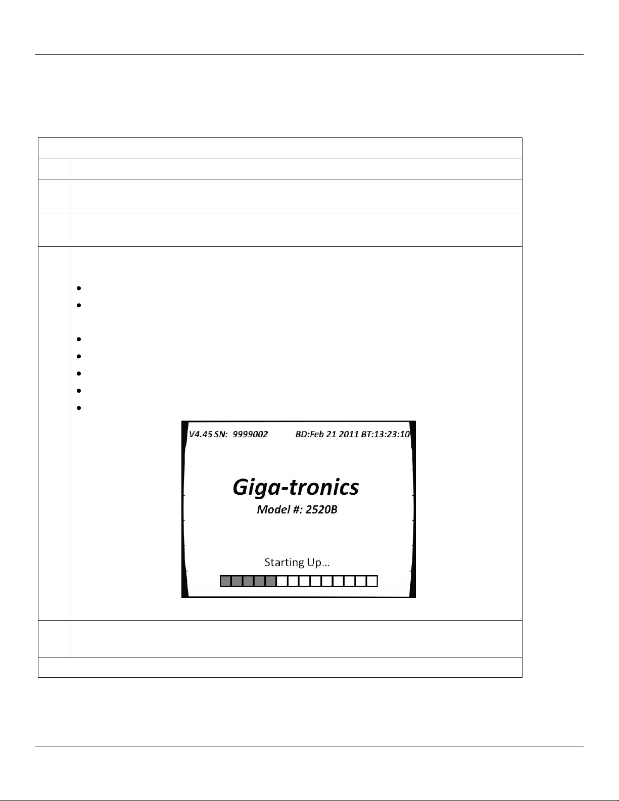
Press the power switch on the front panel of the 2500B. The 2500B displays the following
sequence of screens:
“Initializing” momentarily appears on the display.
The screen shown in Figure 1 appears.
The following information is displayed on the start-up screen:
The firmware version
The serial number of the 2500B
The Build Date (BD) or the firmware version
The Build Time (BT) of the firmware version
A progress bar at the bottom of the screen
Figure 1: 2500B Start Up
4.
Upon the successful conclusion of start-up, the CW Menu is displayed.
If error messages occur during start-up: Refer to page 132.
End of Procedure
2.5.3 Start-up the 2500B
Table 4 below describes how to start-up the 2500B.
Table 4: Start-Up the 2500B
Operation Manual, Part Number 34737, Rev C, June 30, 2011 Page 7

Introduction Giga-tronics 2500B Series Microwave Signal Generators
Reset the 2500B to Default Values
Step
Action
1.
Press the power switch on the front of the 2500B to de-energize the instrument. Wait 5 seconds,
then go to the next step.
2.
Push the power switch in to energize the unit. While the message “INITIALIZING” is displayed,
press and hold the Preset button.
3.
When the “Resetting Memory...” screen is displayed, release the PRESET button.
4.
The system continues to power up normally. All information stored in the memory locations is
cleared, and the system resets to factory default settings.
End of Procedure
2.5.4 Reset the 2500B to Factory-Default Values
The 2500B uses non-volatile memory (NVRAM), which is preserved with a battery for storing the instrument’s current
state, saved setups, and lists. If you want to return these saved settings in NVRAM to the default values they were set to
at the factory, perform the procedure below.
Table 5: Reset the 2500B to Default Values
Page 8 Operation Manual, Part Number 34737, Rev C, June 30, 2011
Giga-tronics 2500B Series Microwave Signal Generators Introduction
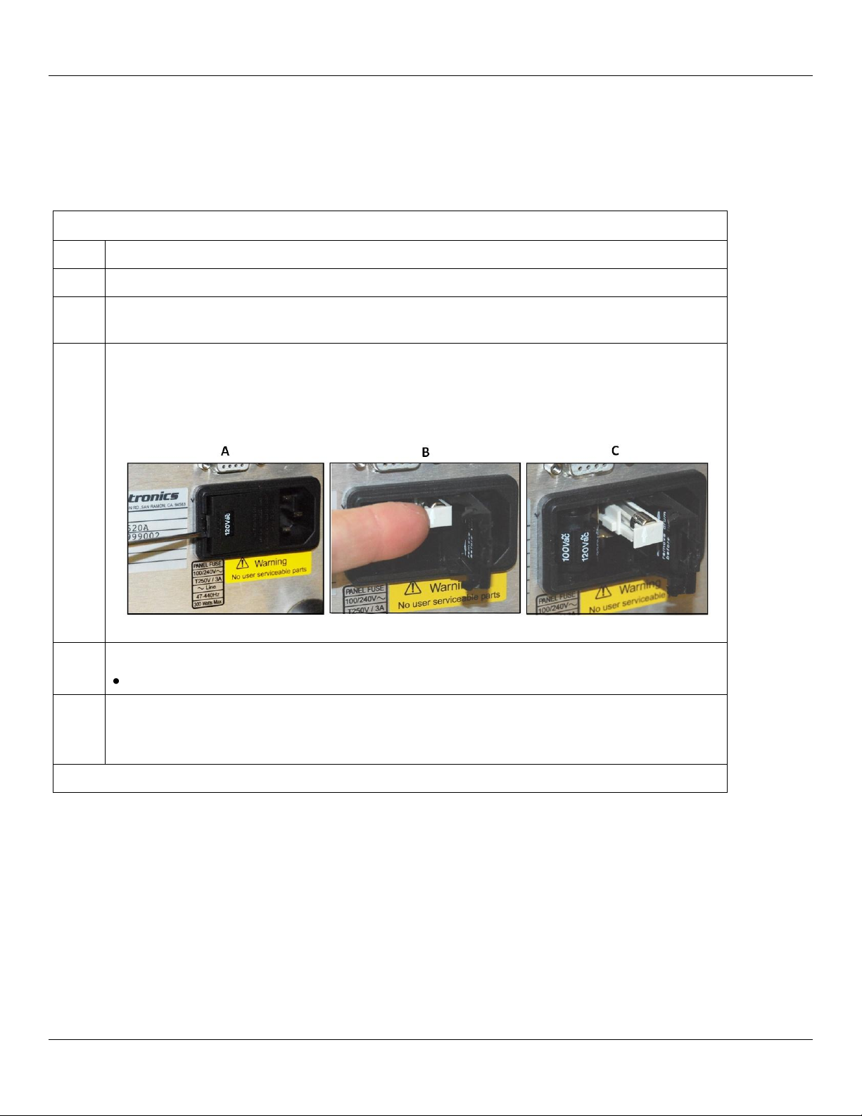
Replace the 2500B Line Fuse
Step
Action
1.
Use the power switch on the front of the 2500B to switch the unit into STANDBY.
2.
On the rear of the 2500B, disconnect the AC line cord. The fuse compartment is located to the
left of the AC line cord socket.
3.
Remove the fuse as follows (see Figure 2):
A) Use a small flat-blade screwdriver to pry open the fuse compartment.
B) Pull out the white fuse holder.
C) You can now remove the fuse from the fuse holder.
Figure 2: 2500B Fuse Holder
4.
Replace the fuse with a new fuse (3 A, Slow-Blow, 250V, Type T).
Push the fuse holder in, and close the fuse compartment door.
5.
Plug the AC line cord into the rear of the 2500B and return the instrument to operation.
NOTE: If the 2500B continues to blow fuses, contact your local Giga-tronics sales representative
or the Giga-tronics factory. See the contact information on page ii of this manual.
End of Procedure
2.5.5 Replace the AC Line Fuse
If the AC line fuse in the 2500B continues to blow, it’s usually an indication of internal problems. If this occurs, contact
Giga-tronics for help (see Table 7 on page 10). Table 6 below describes how to replace the fuse in the 2500B.
Table 6: Replace the 2500B Line Fuse
Operation Manual, Part Number 34737, Rev C, June 30, 2011 Page 9
Introduction Giga-tronics 2500B Series Microwave Signal Generators
Contacting Giga-tronics Customer Service
Email
repairs@gigatronics.com
Telephone (within the United States)
800.726.4442
Telephone
925.328.4669
Fax
925.328.4702
2.6 Shipping, Repair, and Calibration
2.6.1 Shipping the 2500B
If it is necessary to ship the 2500B, observe the following:
Use the best packaging materials available. If possible, reuse the original shipping container.
If the original shipping container is not available, use a strong carton (350 lbs./sq. in. bursting strength) or a wooden
box.
Wrap the instrument in electro-static dissipative material before placing it into the shipping container.
Completely fill the areas on all sides of the instrument with packaging material. Take extra precaution to protect the
front and rear panels.
Seal the package with strong tape or metal bands. Mark the outside of the package clearly, and in bold type, as
follows:
FRAGILE — DELICATE INSTRUMENT
2.6.2 Repairs
The Giga-tronics 2500B microwave signal generator is a robust instrument that has been designed and built for years of
trouble-free service. However, if you experience problems with the instrument, do the following:
1. Contact your local Giga-tronics sales office, or the factory, and be prepared to provide the model, serial number,
and any included options of your instrument, and a description of the problem. To contact the factory directly,
use the following information:
Table 7: Contacting Giga-tronics Customer Service
2. If it is has been determined that you must ship the 2500B to the factory or a service center for repair, you will be
issued a Return Materials Authorization (RMA) number. Use the RMA number in all correspondence regarding
the repair.
3. Pack the 2500B for shipment as described in the previous section, and enclose all relevant information regarding
the problem.
4. Ship the 2500B to the address provided by Giga-tronics Customer Service.
2.6.3 Calibration
Giga-tronics recommends that the 2500B be calibrated every two years. For more information regarding calibration of
your instrument, contact Giga-tronics (see page ii of this manual).
Page 10 Operation Manual, Part Number 34737, Rev C, June 30, 2011
Giga-tronics 2500B Series Microwave Signal Generators Introduction
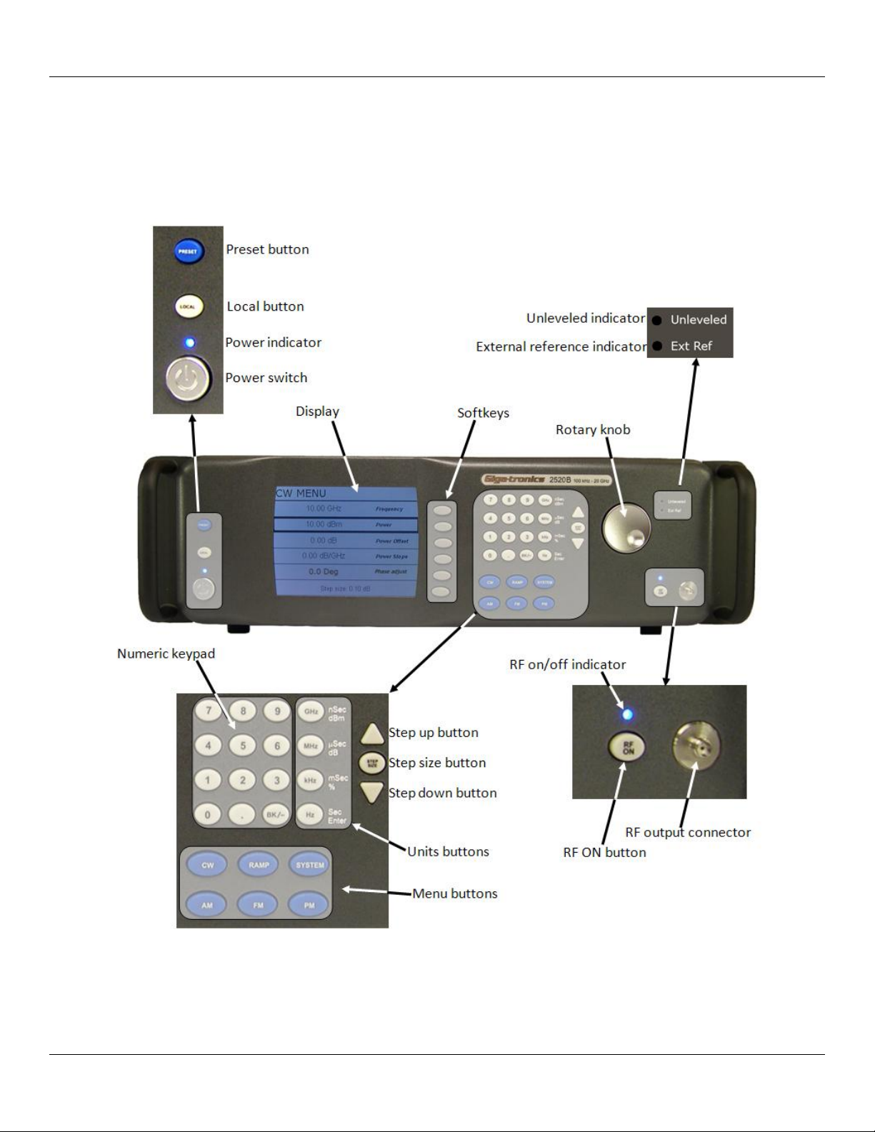
2.7 2500B Front Panel
Figure 3, below, describes the main features of the front panel of the 2500B. Refer to the tables on the following pages
for detailed descriptions of the parts of the front panel.
NOTE: A 2520B is shown in Figure 3. The 2520B front panel is representative of the entire 2500B series.
Figure 3: 2520B Front Panel
Operation Manual, Part Number 34737, Rev C, June 30, 2011 Page 11

Introduction Giga-tronics 2500B Series Microwave Signal Generators
2500B Front Panel
Name
Description
POWER button
Puts the 2500B into one of two states:
STANDBY; power is applied to the internal timebase oscillator. This is to maintain
timebase stability when the 2500B is not in use.
ON; all functions of the 2500B are available for use.
NOTE: To ensure specified performance, allow the 2500B to remain ON or in
STANDBY for at least 30 minutes prior to using the instrument.
POWER indicator
BLUE indicates the instrument is ON and all functions are available.
AMBER indicates the instrument is in STANDBY mode.
LOCAL button
If in REMOTE mode, pressing this button puts the instrument into LOCAL mode.
If the unit is in LOCAL mode: pressing this button displays menus that allow you
to choose the remote command language used during remote operation.
PRESET button
Pressing the PRESET button momentarily presets instrument settings to factory
default values, but does not affect system memory locations, display contrast, or
the GPIB address.
Pressing and holding the PRESET button while the unit is powering up initializes
NVRAM, which includes presetting instrument settings to factory default values
as well as initializing all ten system memory locations, the display contrast, and
the GPIB address.
Display
Displays current instrument settings, and menus for modifying the settings.
The active display is the group of instrument settings and associated menu items
that are currently displayed.
Softkeys
Selects the menu items adjacent to them in the display for modification.
Numeric Keypad
Use for entering numeric settings for generator functions.
STEP SIZE button
Selects and allows editing of the step size by the Step Up/Step Down buttons, rotary
knob, or numeric keypad. To change a step size, see Table 11 on page 18.
RF ON button
Activates RF power output from the 2500B.
Step up/down
buttons
Increases or decreases the selected parameter in the display by the amount specified
by the step size.
Rotary knob
Adjusts the parameter that is selected in the display. When a maximum or minimum
limit is reached, a message appears at the bottom of the display.
Unleveled indicator
When this indicator illuminates, it means that the power output cannot be increased
any further, even though the power output displayed on the front panel may show an
increase. The unleveled point varies with frequency.
External Reference
(Ext Ref) Indicator
Illuminated when the 2500B is operating with an external reference applied.
Table 8: 2500B Front Panel
Page 12 Operation Manual, Part Number 34737, Rev C, June 30, 2011
Giga-tronics 2500B Series Microwave Signal Generators Introduction
2500B Front Panel
Name
Description
RF On/Off Indicator
This indicator has two states:
BLUE indicates the 2500B RF output is active.
NOT illuminated indicates the RF output is not active.
RF Output
The connector type of the RF Output is determined by the upper frequency limit of
the instrument, as follows:
2502B and 2508B: type-N (F)
2520B: SMA (F)
2526B: SMA (F)
2540B: 2.92 mm (F)
2550B: 2.4 mm (F)
NOTE: On some options, the RF output is on the rear panel. Refer to page 130 for
information about all options.
Menu buttons
CW Button
Press this button to display the CW Menu. Shows parameters related to the CW
functions and the Cable Correction functions and their associated menu items.
RAMP Button
Press this button to display either the Ramp Frequency or Ramp Power Menus.
SYSTEM Button
Press this button to display either the System 1 or System 2 menu.
AM Button
Press this button to display the Amplitude Modulation (AM) menus.
FM Button
(Includes phase
modulation menus)
Press this button to display the Frequency Modulation (FM) and Phase Modulation
(ΦM) menus.
PM Button
Press this button to display the Pulse Modulation (PM) menu.
Operation Manual, Part Number 34737, Rev C, June 30, 2011 Page 13
Introduction Giga-tronics 2500B Series Microwave Signal Generators
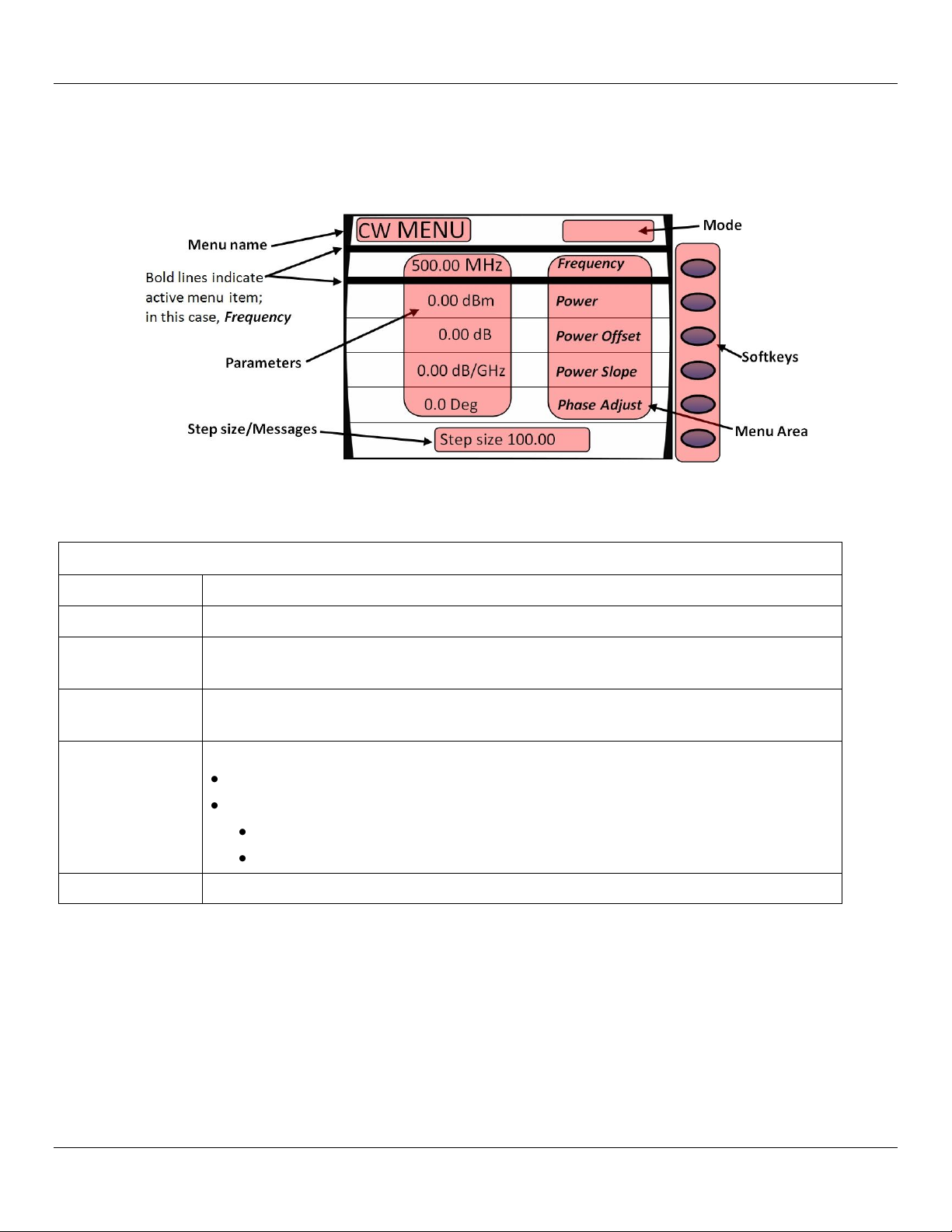
2500B Display Description
Area of Display
Description
Menu Name
Name of the menu that is displayed. This is called the active menu.
Parameters
Displays the current values of the instrument settings associated with the active menu.
Parameters can be modified by the rotary knob or Step Up/Down buttons.
Step
Size/Messages
The step size is the minimum increment by which a parameter can be modified. The step
size can be adjusted. Non-error user messages can also appear in this area.
Menu Area
Displays one of the following:
Submenus
Menu items that can be modified in the active menu.
Menu items are selected (made active) by pressing the adjacent softkey.
The row containing the active parameter has a bold border around it.
Softkeys
Each softkey makes a submenu selectable or parameter active for modification.
2.7.1 Menus
Menus appear on the front panel display of the 2500B. The figure below shows the CW menu to illustrate the common
areas of all menus.
Figure 4: Functional Areas of the 2500B Display
Table 9: 2500B Display Description
Page 14 Operation Manual, Part Number 34737, Rev C, June 30, 2011

Giga-tronics 2500B Series Microwave Signal Generators Introduction
2500B Display Description
Area of Display
Description
Mode
This area may contain one of the following codes:
OFS appears if a power offset greater than 0 dB is set in the CW menu.
SLP appears if a power slope greater than 0 dB/GHz is set in the CW menu.
AM appears if internal or external amplitude modulation is enabled
FM appears if internal or external frequency modulation is enabled
ΦM appears if internal or external phase modulation is enabled
PM appears if internal or external pulse modulation is enabled
EXT LEVEL appears if ALC is set to external
UNLK appears if the Phase Lock Loop is unlocked
OVEN COLD appears if the internal temperature of the 2500B has not reached
operational temperature. It is not recommended to use the 2500B while this indicator is
active.
Operation Manual, Part Number 34737, Rev C, June 30, 2011 Page 15
Introduction Giga-tronics 2500B Series Microwave Signal Generators
AM Ext Menu
Page 37
AM Int Noise Menu
Page 39
AM Int Menu
Page 38
AM
CW
CW MENU
Page 22
FM Ext Menu
Page 45
DC FM Menu
Page 46
FM Int Menu
Page 47
ΦM Ext Menu
Page 48
ΦM Int Menu
Page 49
FM
PM
PM Int Cont Menu
Page 58
PM Int Gated Menu
Page 59
PM Trig Menu
Page 61
PM Burst Menu
Page 63
PM Ext Menu
Page 57
Language Menu 1
Page 83
Language Menu 2
Page 84
Language Menu 3
Page 85
LOCAL
RAMP
Intensity Marker Menu
Page 32
Ramp Freq Start/Stop Sweep Menu
Page 28
Ramp Freq Center/Span Sweep Menu
Page 29
Amplitude Marker Menu
Page 33
SYSTEM
Connectivity Menu
Page 77
Service Menu
Page 78
System Menu
Page 75
Ramp Power Sweep Menu
Page 30
Step Freq Sweep Menu
Page 31
Ethernet Menu
Page 79
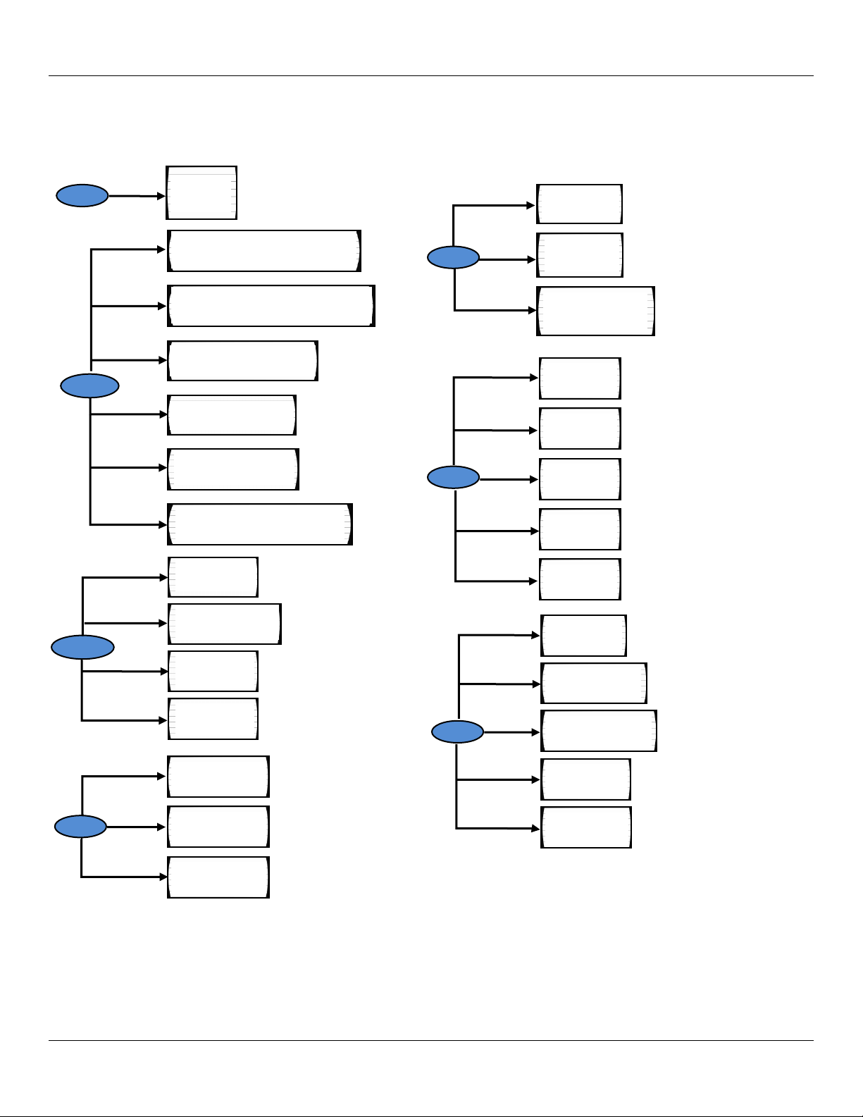
2.7.2 Menu Structure
Figure 5 below shows the structure of the menus of the 2500B. To access the menus, you must first press one of the
blue Menu buttons (see Figure 3 on page 11).
Page 16 Operation Manual, Part Number 34737, Rev C, June 30, 2011
Figure 5: Structure of the 2500B Menus

Giga-tronics 2500B Series Microwave Signal Generators Introduction
Modify a Menu Parameter
Step
Action
1.
Press the softkey adjacent to the parameter you want to modify. Note that the parameter
becomes enclosed in a bold outline box when it is selected.
2.
Modify the value of the parameter by using , , or the numeric keypad (except where
otherwise noted).
End of Procedure
2.7.3 Access the Menus
In local operation, the 2500B menus are accessed via the Menu buttons or Local button on the front panel (see
Figure 3 on page 11). Pressing a Menu button causes the menu for that button to appear on the display. The Menu
buttons are:
o CW
o Ramp
o System
o AM
o FM; includes phase modulation (ΦM) menus
o PM
The LOCAL button allows you to access and modify communication functions during remote operation of the 2500B
(see Figure 3 on page 11).
2.7.4 Softkeys
Use the softkeys (see Figure 4 on page 14) to select a submenu or parameter shown to the left of the softkey, in the
display.
Pressing a softkey next to a submenu displays the submenu and makes its parameters available for viewing and
modification.
Pressing a softkey next to a parameter makes it active for modification.
2.7.5 Modify Menu Parameters
Parameters in the Menu Area of the display (see Figure 4 on page 14) can be modified using either the rotary knob, Step
Up/Down keys, or the numeric keypad (see Figure 3 on page 11), except where otherwise noted. Table 10 below
describes how to modify a menu parameter.
Table 10: Modify a Menu Parameter
Operation Manual, Part Number 34737, Rev C, June 30, 2011 Page 17

Introduction Giga-tronics 2500B Series Microwave Signal Generators
Change the Step Size of a Parameter
Step
Action
1.
Use a softkey to select a parameter. For example, in the CW menu, select Frequency.
2.
Press the Step Size button (see Figure 3 on page 11).
3.
Enter a new step size using the numeric keypad.
4.
Press the appropriate Units button (see Figure 3 on page 11).
5.
Press the Step Size button to save the new step size. Now, when you change the CW frequency using
the Step Up/Step Down buttons or the rotary knob, the parameter changes according to the new Step
Size.
End of Procedure
2.7.6 Modify the Step Size
The step size for a parameter can be modified as described below.
Table 11: Change the Step Size of a Parameter
Page 18 Operation Manual, Part Number 34737, Rev C, June 30, 2011
Giga-tronics 2500B Series Microwave Signal Generators Introduction
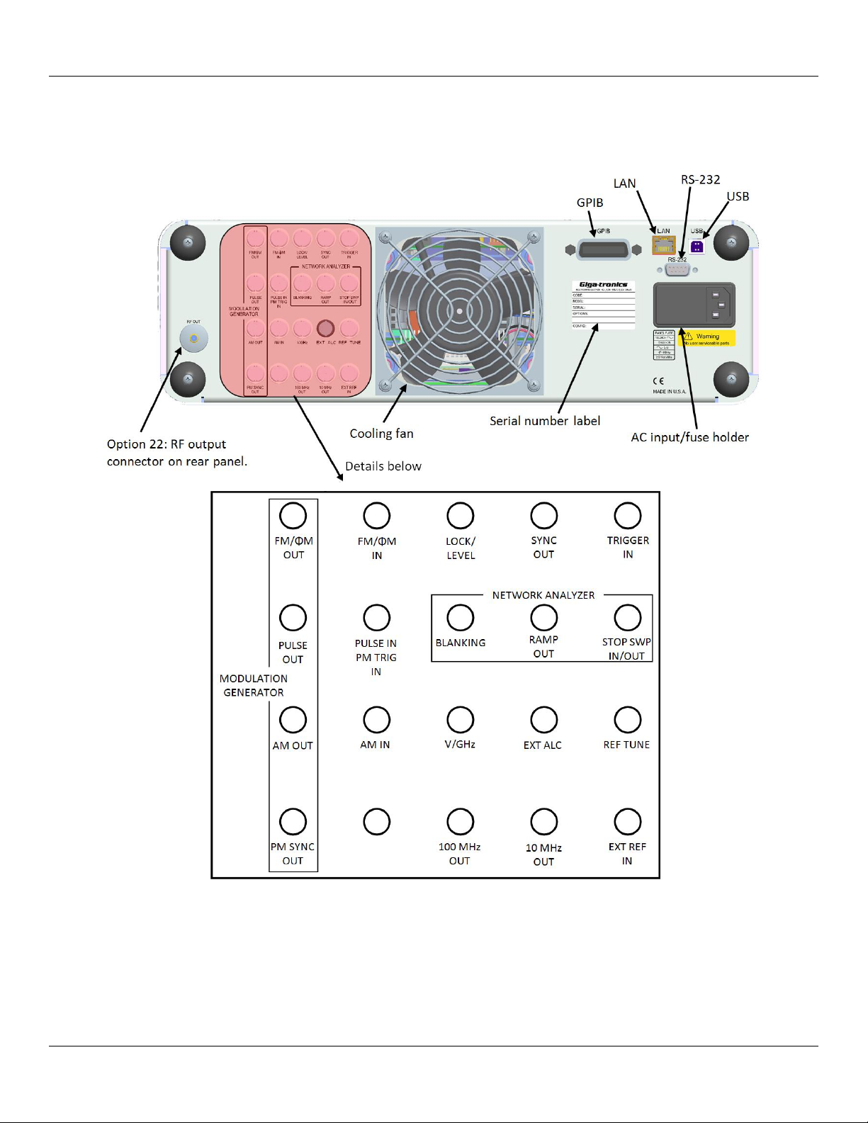
2.8 2500B Rear Panel
Figure 6 below shows the locations of the components on the 2500B rear panel. Descriptions of the rear panel
components are on the following pages.
Figure 6: 2500B Rear Panel
Operation Manual, Part Number 34737, Rev C, June 30, 2011 Page 19

Introduction Giga-tronics 2500B Series Microwave Signal Generators
2500B Rear Panel
Name
Description
EXT ALC
In external leveling, the RF output of the 2500B is detected by either a positive or
negative crystal detector, or power meter with an analog output. The signals from
these devices are connected to the ALC circuitry of the 2500B, which is used to
compensate for standing wave effects or cable and component losses at the input of
the device under test.
MODULATION GENERATOR
FM/φΜ OUT
The internal modulation generator output; 2 Vpp into 10 kΩ.
PULSE OUT
A +4 V video representation of the pulsed RF output signal.
AM OUT
The internal modulation generator output; 2 Vp-p into 10 kΩ.
PM SYNC OUT
A synchronization output pulse of > 75 ns width, TTL levels that can be delayed
relative to the leading edge of the video signal at the PULSE OUT connector.
Limits of delay: ≥ 50 ns, ≤ 10 ms.
FM/φM IN
A 50 Ω input for an external FM or φM modulating signal. The input signal can be
any waveform compatible with bandwidth considerations. A 1-V peak input
produces maximum deviation. Maximum input is ± 1 V p-p.
An externally supplied DC signal can be applied to this input to modulate the
frequency of the CW output.
AM IN
A 600 Ω input for an external AM signal. The input signal can be any waveform
compatible with bandwidth considerations. Maximum input is ± 1 V p-p.
PULSE IN
PM TRIG IN
A Pulse Modulation Input for external Pulse In. The input parameters are:
TTL, polarity selectable, 50 Ω characteristic impedance, 2 kΩ pull-up.
LOCK/LEVEL
+5 Volt output, active high when the 2500B is phase locked and output leveled. The
Lock and Level indicator is valid for CW and List mode.
REF TUNE
A 0 to +10 Volts, high-impedance input for tuning the internal reference in order to
adjust the output frequency approximately +5 ppm. Do not exceed
+15 Volts or apply a negative voltage greater than -1 Volt.
SYNC OUT
In List mode, the unit can be set to generate a pulse at this output when a specified list
point is reached. The RF output can be delayed from the start of the list point up to a
maximum of 10 ms. The pulse width of the SYNC OUT signal is determined as follows:
Pulse width = Step Time - Sync Delay - 10 µs.
In Ramp operation, the pulse occurs at the start of each ramp sweep. In either case,
the output pulse is +5 Volts.
TRIGGER IN
Triggers a List. Accepts a TTL level signal of > 50 ns width.
Table 12: 2500B Rear Panel
Page 20 Operation Manual, Part Number 34737, Rev C, June 30, 2011

Giga-tronics 2500B Series Microwave Signal Generators Introduction
2500B Rear Panel
Name
Description
NETWORK ANALYZER
BLANKING
A +5 Volt output signal occurring at band crossings, filter switches, and retraces for the
duration of those events.
RAMP OUT
A 0 to 10 Volt ramp output scaled to the frequency sweep.
STOP SWP
IN/OUT
Stop Sweep I/O is a 5 Volt, 2 kΩ, active-low signal that temporarily interrupts the
instrument’s frequency or power ramp sweep. This feature is only available with
HP8340 or HP8370 command emulation.
V/GHz
An output voltage that is directly proportional to output frequency. The output is 0.5
Volts per GHz.
100 MHz OUT
> +5 dBm, AC coupled, 100 MHz low-noise reference output signal into 50 Ω.
10 MHz OUT
10 MHz TTL reference output signal into 50 Ω.
EXT REF IN
The external reference input. Can be either a 10 MHz input that is > -5.0 dBm into 50
Ω or a 100 MHz input > +5 dBm. The 100 MHz input level should not exceed
+8 dBm for best performance.
NOTE: If the external frequency reference has excessive noise or drift, this will
degrade the performance of the 2500B.
GPIB
A 24-pin IEEE STD 488.2 connector for control of the instrument during remote
operation using GPIB.
RS-232
A DB-9 connector for control of the instrument during remote operation using
RS-232 serial communications.
USB
A USB connector for control of the instrument during remote operation using USB 2.0
(full speed) communications
Ethernet
An Ethernet connector for control of the instrument during remote operation using
LAN interface communications.
AC Power Input
90 to 253 V ac, auto-sensing, 47 Hz to 440 Hz.
NOTE: All rear panel I/O connectors (except the GPIB, RS-232, LAN, USB, and AC power connections) are type
BNC unless otherwise stated. Some connectors may be inactive due to installed options.
Operation Manual, Part Number 34737, Rev C, June 30, 2011 Page 21

CW Operation Giga-tronics 2500B Series Microwave Signal Generators
Chapter 3 CW Operation
This section describes the CW Menu of the 2500B, and includes an example procedure for generating a CW signal.
The CW specifications of the 2500B start on page 86.
3.1 CW Menu Description
Figure 7: CW Menu
Page 22 Operation Manual, Part Number 34737, Rev C, June 30, 2011

Giga-tronics 2500B Series Microwave Signal Generators CW Operation
CW Menu
Parameter
Description
Frequency
The instrument’s center frequency. The range of the center frequency is dependent on the
model number and options of the instrument.
Power
The output power level of the selected frequency. The range of the output power level
also depends on the Power Offset and Power Slope settings in the CW menu, as well as
other settings of the instrument.
Power Offset
The Power Offset feature increases the instrument’s output power by the amount of the
Power Offset setting, without changing the Power level as shown in the display. This allows
you to compensate for the insertion or conversion loss of components that are attached to
the instrument’s RF output. An example is shown in Figure 8.
Figure 8: Power Offset Example
The Power Offset indicator (OFS) appears in the upper right-hand corner of the display
when any power offset value greater than 0.00 dB is entered.
Power Slope
The power slope feature increases the instrument’s output power linearly as a function of
the output frequency. The power slope function allows you to automatically compensate
for insertion/conversion losses of components attached to the instrument’s RF output that
exhibit a linear loss characteristic with frequency. The Power Slope indicator (SLP) appears
in the upper right-hand corner of the display when the power slope is greater than 0.00
dB/GHz.
Phase Adjust
This menu item displays and allows you to modify the phase of the output signal. Note the
following:
The phase of the signal is maintained until the phase is readjusted or whenever the
instrument frequency setting is changed.
When the instrument frequency setting is changed, the phase adjust setting is reset to
0 degrees.
Phase Adjust is specified for a minimum frequency range of 500 MHz to the maximum
frequency range of the instrument. Phase adjust is available for frequencies below 500
MHz, however the output response time of the phase adjust is decreased.
Table 13: CW Menu
Operation Manual, Part Number 34737, Rev C, June 30, 2011 Page 23

CW Operation Giga-tronics 2500B Series Microwave Signal Generators
Generate a CW Signal
Step
Action
1.
Press .
2.
Select Frequency. Enter the 1.250 GHz using the numeric keypad, , or .
NOTE: Whenever the frequency of the instrument is changed, the Phase Adjust setting resets to 0
degrees. The Phase Adjust range is 500 MHz to the maximum frequency of the instrument.
3.
If the step attenuator option IS INSTALLED in the unit:
Go to the Step 4.
If the step attenuator option IS NOT installed in the unit:
Go to Step 5.
Softkey
CW
3.2 Generate a CW Signal
This procedure describes how to setup the 2500B to generate a CW signal with the following characteristics:
Frequency: 1.250 GHz
Power: 1 dBm
Power offset: adjust as necessary to compensate for losses in test setup
Power slope: adjust as necessary to compensate for losses that vary linearly with frequency
Phase adjust: adjust as necessary
NOTE: The example procedure below uses specific parameters to illustrate how to setup the 2500B. You can use this
procedure for real-life situations by simply changing the parameters to fit your needs.
Use this setup where a single, un-modulated frequency is needed, and where losses and frequency response are not
significant in the cables and fixtures connecting to the DUT.
This procedure describes how to set up the 2500B to generate a continuous wave (CW) signal at a specified output
power level. This procedure is also used to configure the carrier signal when modulation is used.
Table 14: Generate a CW Signal
Page 24 Operation Manual, Part Number 34737, Rev C, June 30, 2011

Giga-tronics 2500B Series Microwave Signal Generators CW Operation
Generate a CW Signal
Step
Action
4.
The step attenuator, if installed, can be set to one of two modes:
Auto Mode: In this mode, the step attenuator automatically switches attenuation state as the
instrument’s output power level setting is varied. To set the step attenuator so that it
automatically switches attenuation levels with changes in output power level;
1. Press .
2. Select System Menu.
3. Select Attenuation.
4. Use or Attenuation to select Auto.
Fixed Mode: In this mode, the step attenuator is set to a fixed level of attenuation. The
maximum and minimum settable range is +25 dB to -20 dB relative to the attenuator setting. To
set the step attenuator so that it remains fixed at a desired level of attenuation
1. Press .
2. Select System Menu.
3. Select Attenuation.
4. Use , or Attenuation to select the level of attenuation.
5.
Return to the main CW menu if necessary by pressing .
6.
Select Power, and enter 1.00 dBm:
1. On the numeric keypad (see Figure 3 on page 11), enter 1.00.
2. Press the GHz/nSec/dBm units button
NOTE: You can also change the value by using the keys, or .
NEXT STEP: The insertion/conversion loss compensation features of the 2500B includes the:
Power Offset feature, which is used to compensate for a fixed level of insertion or conversion loss;
Power Slope feature, which is used to compensate for insertion or conversion loss that linearly varies with
frequency.
7.
If YOU WANT to use the insertion/conversion loss compensation features of the 2500B:
Perform either, or both, Step 8 and Step 9 as necessary.
If you DO NOT want to use the insertion/conversion loss compensation features of the 2500B:
Go to Step 10.
8.
To compensate for a fixed level of loss;
1. Select Power Offset.
2. Enter the desired loss correction using the numeric keypad, , or . Note that when a
correction factor is entered, OFS appears in the upper right corner of the display.
Softkey
Softkey
CW
Softkey
Softkey
Softkey
System
Softkey
Softkey
Softkey
System
Operation Manual, Part Number 34737, Rev C, June 30, 2011 Page 25

CW Operation Giga-tronics 2500B Series Microwave Signal Generators
Generate a CW Signal
Step
Action
9.
To compensate for a loss that varies linearly with frequency;
1. Select Power Slope.
2. Enter the desired correction factor using the numeric keypad, keys, or . Note that when
this correction factor is entered, SLP appears in the upper right corner of the display.
10.
To adjust the phase of the output; select Phase Adjust, and enter the desired phase
shift using the numeric keypad, keys, or .
11.
If the RF ON indicator is not lit, press the RF ON button to enable the RF output.
12.
Verify that the Unleveled indicator is not lit.
13.
If the Unleveled indicator is lit, then the combination of output power level, power offset, power
slope, and step attenuator mode (if applicable) is set inappropriately, and the RF output is unleveled.
Adjust the combination of settings until the Unleveled indicator turns off.
End of Procedure
Softkey
Softkey
Page 26 Operation Manual, Part Number 34737, Rev C, June 30, 2011

Giga-tronics 2500B Series Microwave Signal Generators Ramp Operation
Chapter 4 Ramp Operation
This chapter describes in detail the menus and parameters in the Ramp Menus. This chapter includes example
procedures for using the 2500B front panel controls to setup ramps.
4.1 Ramp Menu Description
The Ramp Menu provides a powerful, flexible suite of functions to meet the most demanding test requirements. The
figure below shows the Ramp Main Menu.
Ramps can be set up for frequency or power. When a ramp is created, one parameter is swept (either frequency or
power), and the other parameter is held constant.
For example, if a frequency ramp is created, the power is held constant over the range of ramp frequencies. Conversely,
if a power ramp is created, the frequency is held constant over the range of power.
Figure 9: Ramp Main Menu
Operation Manual, Part Number 34737, Rev C, June 30, 2011 Page 27

Ramp Operation Giga-tronics 2500B Series Microwave Signal Generators
Ramp Menus
Submenu
Parameter
Figure 10: Ramp Freq Start/Stop Sweep Menu
Ramp Freq
Start/Stop Sweep
Menu
(see Figure 10)
Start Frequency This is the starting frequency of the frequency sweep. The start
frequency must be less than the stop frequency. If the start frequency is set higher
than the stop frequency, the stop frequency is automatically adjusted to the same
value.
Stop Frequency This is the ending frequency of the frequency sweep. The stop
frequency must be greater than the start frequency. If it is set lower than the start
frequency, the start frequency is automatically set to the same value.
Power The output power level during the frequency sweep. The range of the power
level depends on the next two menu items and other settings of the instrument.
The power level is held constant during a frequency sweep.
Sweep Time This is the duration of a single sweep.
Resolution The sweep resolution is the number of frequency steps to be included in
the frequency sweep.
The step resolution can be set to:
401, 801, or 1601, or
Analog sweep
Use the step up/step down buttons or rotary knob to set the resolution; the numeric
keypad cannot be used.
Table 15: Ramp Menus
Page 28 Operation Manual, Part Number 34737, Rev C, June 30, 2011

Giga-tronics 2500B Series Microwave Signal Generators Ramp Operation
Ramp Menus
Submenu
Parameter
Figure 11: Ramp Freq Center/Span Sweep Menu
Ramp Freq
Center/Span
Sweep Menu
(see Figure 11)
Center Freq The center frequency of the frequency span that is swept.
Span This menu item displays and allows you to modify the frequency range of the
ramp (sweep). The span is centered on the Center frequency.
Power The output power level during the center/span frequency sweep. The range of
the power level can be set to any valid power setting of the instrument.
Sweep Time This is the duration of one cycle of a frequency sweep.
Resolution This is the number of frequency steps in the frequency sweep.
The resolution can be set to:
401, 801, or 1601, or
Analog sweep.
Analog Sweep provides a number of smooth frequency segments across a frequency range
as opposed to the Digital Sweep feature which is made up of individual frequency points,
from 401/801/1601 discrete frequency points.
A single Analog Sweep is comprised of a number of smaller sweep segments. Analog
sweeps are broken down into anywhere from 1 to 685 sweep segments. Each segment is a
smooth frequency ramp. The segment size depends on the current operating band and the
sweep speed. Breaking a sweep into smaller segments allows the instrument to correct for
RF amplitude variations between segments. See figure below.
Use the step up/step down buttons or rotary knob to set the resolution; the numeric
keypad cannot be used.
Operation Manual, Part Number 34737, Rev C, June 30, 2011 Page 29

Ramp Operation Giga-tronics 2500B Series Microwave Signal Generators
Ramp Menus
Submenu
Parameter
Figure 12: Ramp Power Sweep Menu
Ramp Power
Sweep Menu
(see Figure 12)
This function sweeps the RF output power level linearly from a start power level to a
stop power level in a set duration, then repeats the sweep. The power level can sweep
from a lower to a higher power level, or in the reverse direction. The output frequency
is held constant during a power sweep. The maximum settable range for ramp power
sweep is 45 dB.
NOTE: As soon as the Ramp Power menu is chosen, the instrument calculates the ramp,
and then begins sweeping the output power. The ramp is recalculated whenever a
parameter is changed. During calculations, the following message is shown at the
bottom of the display:
PREPARING SWEEP DATA...
When the calculations are complete and the output is actively sweeping, the following
message is shown:
RAMP SWEEPING
Start Power This is the beginning power level of the power level sweep.
The range for the start power parameter is -20 dBm to +25 dBm if the step
attenuator option is not installed in the instrument.
If the step attenuator option is installed, the start power range is from 25 dB above
to 20 dB below the step attenuator setting.
Stop Power This is the ending power level of the sweep.
If the step attenuator option is installed, the stop power range is from 25 dB above
to 20 dB below the step attenuator setting chosen.
If the step attenuator option is not installed in the instrument, the range for the
stop power parameter is -20 dBm to +25 dBm.
Frequency This is the frequency that undergoes a power ramp. The range of
adjustment of this parameter is dependent on the model number of the instrument.
Sweep Time This is the amount of time that elapses for one cycle of a power level
sweep to complete.
Step size Power step size
Page 30 Operation Manual, Part Number 34737, Rev C, June 30, 2011

Giga-tronics 2500B Series Microwave Signal Generators Ramp Operation
Ramp Menus
Submenu
Parameter
Figure 13: Step Freq Sweep Menu
Step Freq Sweep
Menu
(see Figure 13)
This menu allows you to view and modify settings for the frequency sweep feature.
Note the following:
When this feature is used, the frequency of the RF output sweeps linearly from a
settable start frequency to a settable stop frequency, over a sweep time, then
repeats the sweep.
The sweep occurs in a set number of equal increments, as determined by the
Resolution setting.
The output power is held at the same level during a frequency sweep.
NOTE: As soon as the Step Freq Sweep menu is chosen, the instrument calculates the
ramp, and then begins sweeping the output frequency. The ramp is recalculated
whenever a parameter is changed. During calculations, the following message is shown
at the bottom of the display:
PREPARING SWEEPING DATA...
When the calculations are complete and the output is actively sweeping, the following
message is shown:
RAMP SWEEPING
Start Frequency This is the starting frequency of the frequency sweep. The start
frequency must be less than the stop frequency. If the start frequency is set higher than
the stop frequency, the stop frequency is automatically adjusted to the same value.
Stop Frequency This is the ending frequency of the frequency sweep. The stop
frequency must be greater than the start frequency. If it is set lower than the start
frequency, the start frequency is automatically adjusted to the same value.
Power The output power level during the frequency sweep. The range of the power
level depends on the configuration and settings of the instrument.
Step Time The duration of the step.
Step Size Frequency step size
Operation Manual, Part Number 34737, Rev C, June 30, 2011 Page 31

Ramp Operation Giga-tronics 2500B Series Microwave Signal Generators
Ramp Menus
Submenu
Parameter
Figure 14: Intensity Marker Menu
Intensity Marker
Menu
(see Figure 14)
The Intensity Marker Menu allows you to view and modify settings related to the
instrument’s Intensity Markers used in conjunction with the frequency sweep. Five
intensity markers can be set.
Intensity Markers These five items allow you to set the frequency of the intensity
markers using the numeric key pad. The marker is activated and deactivated by
pressing the marker soft key.
Markers All On/Off This menu item allows you to toggle the states of all 5 markers in
the Intensity Marker menu. Pressing the adjacent softkey toggles all marker states to
be all on or all off.
Page 32 Operation Manual, Part Number 34737, Rev C, June 30, 2011

Giga-tronics 2500B Series Microwave Signal Generators Ramp Operation
Ramp Menus
Submenu
Parameter
Figure 15: Amplitude Marker Menu
Amplitude Markers
Menu
(see Figure 15)
The Amplitude Marker Menu allows you to view and modify settings related to the
instrument’s Amplitude Markers used in conjunction with the frequency sweep. Five
amplitude markers can be set.
AmplMrkr1 through AmplMrkr2 These 5 items allow you to set the frequency of the
amplitude markers using the numeric key pad. The marker is activated and deactivated
by pressing the adjacent amplitude marker soft key.
Markers All On/Off This menu item allows you to toggle the states of all markers in the
Amplitude Marker menu. Pressing the adjacent soft key toggles all marker states to be
all on or all off.
Operation Manual, Part Number 34737, Rev C, June 30, 2011 Page 33

Ramp Operation Giga-tronics 2500B Series Microwave Signal Generators
Softkey
Softkey
Softkey
Generate a Frequency-Swept Signal
Step
Action
1.
Press to display the Sweep Main menu.
2.
Press RAMP FREQ Start/Stop Sweep menu.
3.
Select Start Frequency, and enter 1.00 GHz using the numeric keypad (and Units
buttons), , or .
4.
Select Stop Frequency, and enter 2.00 GHz using the numeric keypad (and Units
buttons), , or .
NOTE: The ramp stop frequency must be set equal to or greater than the ramp start frequency.
5.
Select Power and enter the 1.00 dBm using the numeric keypad (and Units buttons),
, or .
6.
Select Sweep Time, and enter 1.00 seconds using the numeric keypad (and Units
buttons), , or .
7.
Resolution, and select 401 using .
Select
NOTE: The resolution setting determines the number of discreet frequency steps that will be included
in the frequency ramp. Three resolutions are available: 401, 801, or 1601. Higher resolution settings
will result in more steps and a finer resolution ramp.
8.
If the RF ON indicator is not lit, press the RF ON button to enable the RF output. When the RF output is
enabled, the RF ON indicator is illuminated blue.
End of Procedure
Softkey
Softkey
Softkey
RAMP
4.2 Generate a Frequency-Swept Signal
This procedure describes how to set up a signal at a constant power level that sweeps linearly from a start frequency to
a stop frequency over a set duration, then repeats the sweep. The signal will be set up with the following characteristics:
Start frequency: 1.00 GHz
Stop frequency: 2.00 GHz
Power level: 1.00 dBm
NOTE: The example procedure in this section uses specific parameters to illustrate how to setup the 2500B. You can use
this procedure for real-life situations by simply changing the parameters to fit your needs.
Table 16: Generate a Frequency Swept Signal
Page 34 Operation Manual, Part Number 34737, Rev C, June 30, 2011

Giga-tronics 2500B Series Microwave Signal Generators Ramp Operation
RAMP
Softkey
Softkey
Softkey
Softkey
Softkey
Softkey
Softkey
Generate a Power-Swept Signal
Step
Action
1.
Press
to display the Sweep Main menu.
2.
Select
Ramp Power Sweep Menu.
3.
Select Start Power, and enter 0.00 dBm using the numeric keypad (and Units buttons),
, or .
4.
If the step attenuator option IS INSTALLED in the unit; Go to Step 5.
If the step attenuator option IS NOT installed in the unit; Go to Step 6.
5.
Attenuation in the RAMP POWER menu, and use to select the desired
Select
step attenuator level.
NOTE: The step attenuator cannot be set to auto-switch while in power sweep mode. Choose a step
attenuator level so that the range of the power sweep will be within 25 dB above and 20 dB below the
step attenuator level chosen.
6.
Select Stop Power, and enter 5.00 dBm using the numeric keypad (and Units buttons) ,
, or .
NOTE: The ramp stop power level can be set equal to, greater than, or less than the ramp start power
level.
7.
Select Frequency, and enter 1.00 GHz using the numeric keypad (and Units buttons) ,
, or .
8.
Select Sweep Time, and enter 5.00 seconds using the numeric keypad (and Units
buttons), , or .
9.
Select Step Size, and enter 0.10 dB using the numeric keypad (and Units buttons),
, or .
10.
If the RF ON indicator is not lit, press the RF ON button to enable the RF output.
When the RF output is enabled, the RF ON indicator is illuminated blue.
End of Procedure
4.3 Generate a Power-Swept Signal
This procedure describes how to set up the 2500B to generate a signal at a constant frequency that sweeps linearly from
a set start power level to a set stop power level over a set amount of time, and repeats the sweep. The signal will be
setup with the following characteristics:
Start power: 0.00 dBm
Stop power: 5.00 dBm
Frequency: 1.00 GHz
Sweep time: 5.00 second
Step size: 0.10 dB
NOTE: The example procedure in this section uses specific parameters to illustrate how to set up the 2500B. You can
use this procedure for real-life situations by simply changing the parameters to fit your needs.
Table 17: Generate a Power Swept Signal
Operation Manual, Part Number 34737, Rev C, June 30, 2011 Page 35

Modulation Operation Giga-tronics 2500B Series Microwave Signal Generators
Chapter 5 Modulation Operation
This section describes the modulation menus in the 2500B, and includes example procedures for setting up modulated
test signals.
NOTE: This section only applies to instruments with Option 17A or Option 17B installed.
Option 17A: add internal and external modulation
Option 17B: add external modulation
5.1 AM Menu Description
Press the AM Menu button to display the AM Main Menu. From here, you can go to one of three submenus. See Figure
16 below.
The following pages describe the AM menus and their parameters.
Figure 16: AM Main Menu and Submenus
Page 36 Operation Manual, Part Number 34737, Rev C, June 30, 2011

Giga-tronics 2500B Series Microwave Signal Generators Modulation Operation
AM Menus
Submenu
Parameter
Figure 17: AM External Menu
AM Ext Menu
(see Figure 17)
The AM External Menu allows you to view and modify settings for external
amplitude modulation mode. In this mode, the RF output signal is modulated
according to the signal that is applied to the rear panel AM IN connector.
Parameters in this submenu that can be modified are:
AM Enables or disables amplitude modulation. The active menu, that is, the menu
that is currently being displayed, determines the AM mode that is used. Pressing
either the adjacent soft key or the Step Up or Step Down buttons toggle the AM
state.
The AM indicator is displayed in the upper right-hand corner of the display when
amplitude modulation is turned on.
Sensitivity Determines the percentage of modulation produced per Volt of input
into the AM IN connector. The AM sensitivity can be modified using the numeric
keypad, the step up/step down buttons, or the rotary knob. The AM sensitivity
range is 0 to 95 %/Volt, and the step size can be set in the range of 0.10 to 47.5
%/Volt.
Table 18: AM Menus
Operation Manual, Part Number 34737, Rev C, June 30, 2011 Page 37

Modulation Operation Giga-tronics 2500B Series Microwave Signal Generators
AM Menus
Submenu
Parameter
Figure 18: AM Internal Waveform
AM Int Menu
(see Figure 18)
The AM Internal Waveform menu allows you to view and modify settings in which
the modulating signal is an internally-generated sine, triangle, ramp, or square
waveform (the signal at the AM IN connector is not used).
Parameters in this submenu are:
AM Enables or disables amplitude modulation. The active menu (the menu that is
currently being displayed), determines the AM mode that is used. Pressing the
adjacent softkey or the Step Up or Step Down buttons toggle the AM state.
Depth The amount of modulation of the carrier amplitude expressed as a
percentage. The maximum depth adjustment available is 95 %.
Rate The frequency (rate) of the internal modulating signal. The frequency cannot
be set above 100 kHz.
Waveform Allows you to choose the type of waveform used as the internal
modulating signal. The available selections are Sine, Triangle (symmetrical triangle
wave), Ramp (positive going ramp), or Square (50 % duty cycle square wave).
Page 38 Operation Manual, Part Number 34737, Rev C, June 30, 2011

Giga-tronics 2500B Series Microwave Signal Generators Modulation Operation
AM Menus
Submenu
Parameter
Figure 19: AM - Internal Noise Menu
AM Int Noise Menu
(see Figure 19)
The AM - Internal Noise menu allows you to view and modify settings related to an
internal amplitude modulation mode in which the modulating signal is an internallygenerated Gaussian noise source (the signal at the AM IN connector is not used).
AM Enables or disables amplitude modulation. The active menu, (the menu
currently displayed), determines the AM mode that is used. Pressing the adjacent
softkey or the Step Up or Step Down buttons toggles the AM state.
Depth This menu item allows you to view and modify the AM depth setting, which is
the amount of modulation of the carrier amplitude expressed as a percentage.
Operation Manual, Part Number 34737, Rev C, June 30, 2011 Page 39

Modulation Operation Giga-tronics 2500B Series Microwave Signal Generators
Generate an Internally Modulated AM Signal
Step
Action
1.
Verify that the RF output is NOT energized by checking the RF on/off indicator on the front of the
2500B (see Figure 3 on page 11). If the indicator is lit, press the button to
de-energize the RF output.
2.
Connect the RF output on the 2500B as needed.
3.
Press the menu button (see Figure 3 on page 11).
4.
In the CW menu, select 1.00 GHz for the frequency of the AM signal:
1. Press Frequency.
2. On the numeric keypad on the front panel of the 2500B, enter 1.
3. Press the GHz Units button (next to the numeric keypad) to enter the new frequency.
NOTE: You can also use the keys and to change the frequency.
5.
In the CW menu, select 1.00 dBm for the power level of the AM signal:
1. Press Power.
2. On the numeric keypad on the front panel of the 2500B, enter 1.
3. Press the GHz (nSec/dBm) Units button (next to the numeric keypad) to enter the new power
level.
NOTE: You can also use the keys and to change the power level.
6.
Press the menu button.
7.
In the AM Main Menu, press AM Int Menu. This opens the AM — Internal Waveform
submenu (see Figure 18 on page 38).
Soft Button
AM
Soft Button
Soft Button
CW
RF ON
5.2 Generate an Internally Modulated AM Signal
The procedure below describes how to generate an AM signal with the following characteristics:
Carrier frequency = 1.00 GHz
Carrier power = 1.00 dBm
Depth of AM modulation = 20 %
Rate of AM modulation = 50 kHz
Modulating waveform = sine wave
NOTE: The example procedure in this section uses specific parameters to illustrate how to setup the 2500B. You can use
this procedure for real-life situations by simply changing the parameters to fit your needs.
Table 19: Generate an Internally Modulated AM Signal
Page 40 Operation Manual, Part Number 34737, Rev C, June 30, 2011

Giga-tronics 2500B Series Microwave Signal Generators Modulation Operation
Generate an Internally Modulated AM Signal
Step
Action
8.
In the AM — Internal Waveform submenu, set the following parameters:
1. Turn on AM modulation; press AM.
2. Set the depth of AM modulation; press Depth.
a. Use the numeric keypad, keys, or to change the depth of AM modulation to 20
%.
3. Set the rate of AM modulation; press Rate.
a. Use the numeric keypad, keys, or to change the rate of AM modulation to 50
kHz.
4. Set the type of waveform used for AM modulation as a sine wave; press Waveform
until Sine selected.
9.
Press the button to energize the RF output of the 2500B.
End of Procedure
RF ON
Soft Button
Soft Button
Soft Button
Soft Button
5.3 Generate an Externally Modulated AM Signal
The procedure below describes how to generate an AM signal using an external modulation source. The AM signal is set
up to have the following characteristics:
Carrier frequency = 1.00 GHz
Carrier power = 1.00 dBm
Depth of AM modulation = 50 %/V
Rate of AM modulation = 50 kHz
Modulating waveform = sine wave
NOTE: The example procedure in this section uses specific parameters to illustrate how to setup the 2500B. You can use
this procedure for real-life situations by simply changing the parameters to fit your needs.
Equipment and Materials
External AM modulation source (see specifications in Table 51 on page 95)
Cables and connectors for connecting the AM modulation source to the 2500B
Cables and connectors for connecting device to be tested to the 2500B RF Output
Operation Manual, Part Number 34737, Rev C, June 30, 2011 Page 41

Modulation Operation Giga-tronics 2500B Series Microwave Signal Generators
Generate an Externally Modulated AM Signal
Step
Action
1.
Verify that the RF output is NOT energized by checking the RF on/off indicator on the front of the
2500B (see Figure 3 on page 11). If the indicator is lit, press the button to de-energize
the RF output.
2.
Connect the RF output on the 2500B as needed.
3.
On the rear of the 2500B, locate the AM IN connector (see Figure 6 on page 19).
4.
Connect the external AM modulation source to the AM IN connector (see Table 51 on page 95 for
specifications for the external AM signal).
5.
Press the menu button.
6.
In the CW menu, select 1.00 GHz for the frequency of the AM signal:
1. Press Frequency.
2. On the numeric keypad on the front panel of the 2500B, enter 1.
3. Press the GHz Units button (next to the numeric keypad) to enter the new frequency.
NOTE: You can also use the keys and to change the frequency.
7.
In the CW menu, select 1 dBm for the power level of the AM signal:
1. Press Power.
2. On the numeric keypad on the front panel of the 2500B, enter 1.
3. Press the GHz (nSec/dBm) Units button (next to the numeric keypad) to enter the new power
level.
NOTE: You can also use the keys and to change the power level.
8.
Press to display the AM Main Menu (see Figure 16 on page 36).
9.
Press AM Ext Menu.
10.
Press AM to switch AM mode ON.
11.
Press Sensitivity.
12.
Adjust the sensitivity to 50 %/Volt:
1. On the numeric keypad, enter 50.
2. Press the kHz/mSec/ % Units button (see Figure 3 on page 11).
NOTE: You can also set the sensitivity by the using the keys and .
13.
Set the external AM modulation source for the following output:
Frequency: 50 kHz
Amplitude: 1 V peak (or 2 V peak-to-peak)
Output waveform: sine wave
Soft Button
Soft Button
Soft Button
AM
Soft Button
Soft Button
CW
RF ON
Table 20: Generate an Externally Modulated AM Signal
Page 42 Operation Manual, Part Number 34737, Rev C, June 30, 2011

Giga-tronics 2500B Series Microwave Signal Generators Modulation Operation
Generate an Externally Modulated AM Signal
Step
Action
14.
Energize the output of the external AM modulation source.
15.
Energize the RF output of the 2500B.
End of Procedure
Operation Manual, Part Number 34737, Rev C, June 30, 2011 Page 43

Modulation Operation Giga-tronics 2500B Series Microwave Signal Generators
5.4 FM Menu Description
Pressing the FM menu button displays the FM Main Menu. From here, you can choose from among five submenus for
modifying parameters for frequency and phase modulation. See Figure 20.
The following pages describe the FM menu and submenus in detail.
NOTE: The FM Menu includes phase modulation modes.
Figure 20: FM Main Menu and Submenus
Page 44 Operation Manual, Part Number 34737, Rev C, June 30, 2011

Giga-tronics 2500B Series Microwave Signal Generators Modulation Operation
FM Menus
Submenu
Parameter
Figure 21: FM External Menu
FM Ext Menu
(see Figure 21)
The FM External menu allows you to view and modify settings for external
frequency modulation mode, which is used when the modulating signal is provided
externally. In external FM mode, the RF output signal is modulated by the signal that
is applied to the rear panel FM/φM IN connector.
Items in this submenu that can be modified are:
FM Enables or disables frequency modulation. The active menu, (the menu currently
displayed), determines the FM mode that is used. Pressing the adjacent soft key or
the Step Up or Step Down buttons toggles the FM state.
Sensitivity Determines how much the RF output deviates in frequency per Volt of
signal at the rear panel FM/φM IN connector.
Table 21: FM Menus
Operation Manual, Part Number 34737, Rev C, June 30, 2011 Page 45

Modulation Operation Giga-tronics 2500B Series Microwave Signal Generators
FM Menus
Submenu
Parameter
Figure 22: DC FM Menu
DC FM Menu
(see Figure 22)
In DC FM mode, the RF output signal is modulated by an external signal that is
applied to the rear panel FM/φM IN connector. Note the following:
DC FM is available on all models including models with option 17A.
Frequency range for DC FM operation is 500 MHz to the maximum frequency of
the instrument with a fixed maximum deviation of 125 kHz.
DC FM operation is available for frequencies above 500 MHz; however,
maximum deviation is limited to the frequency band maximum deviation of the
output frequency.
There is one settable item in this submenu:
DC FM Enables or disables DC frequency modulation. The active menu, (the menu
currently displayed), determines the FM mode that is used. Pressing the adjacent
soft key or the Step Up or Step Down buttons toggle the FM state.
Page 46 Operation Manual, Part Number 34737, Rev C, June 30, 2011

Giga-tronics 2500B Series Microwave Signal Generators Modulation Operation
FM Menus
Submenu
Parameter
Figure 23: FM Internal Menu
FM Int Menu
(see Figure 23)
Allows you to view and modify settings related to an internal frequency modulation
mode in which the modulating signal is an internally-generated sine, triangle, ramp,
or square waveform (the signal at the FM/φM IN connector is not used).
Settable menu items are:
FM Switches FM Internal on and off. FM Internal is an internally driven modulation.
FM - Internal can only be activated or deactivated using the step up/step down
buttons.
Deviation Determines how much (in Hertz) the RF output deviates in frequency
when modulated by the internal source.
Rate The rate (frequency) of the internal modulating signal.
Waveform Allows you to view and choose the type of waveform used as the internal
modulating signal. The available selections are Sine, Triangle (symmetrical triangle
wave), Ramp (positive going ramp), or Square (50 % duty cycle square wave).
Operation Manual, Part Number 34737, Rev C, June 30, 2011 Page 47

Modulation Operation Giga-tronics 2500B Series Microwave Signal Generators
FM Menus
Submenu
Parameter
Figure 24: ΦM External Menu
ΦM Ext Menu
(see Figure 24)
The ΦM External menu allows you to view and modify settings for external phase
modulation mode, which is used when the modulating signal is provided externally.
In external ΦM mode, the RF output signal is modulated by a signal that is applied
to the rear panel FM/φM IN connector.
Items in this submenu that can be modified are:
ΦM Enables or disables modulation. The active menu, (the menu that is currently
displayed), determines the ΦM mode that is used. Pressing either the adjacent
softkey or the Step Up or Step Down buttons toggle the ΦM state.
Sensitivity Use to view and modify the external ΦM sensitivity setting, which
determines how much the RF output phase deviates in radians per Volt of signal at
the rear panel FM/φM IN connector.
Page 48 Operation Manual, Part Number 34737, Rev C, June 30, 2011

Giga-tronics 2500B Series Microwave Signal Generators Modulation Operation
FM Menus
Submenu
Parameter
Figure 25: ΦM Internal Menu
ΦM Int Menu
(see Figure 25)
The ΦM -Internal menu allows you to view and modify settings related to an
internal phase modulation mode in which the modulating signal is an
internally-generated sine, triangle, ramp, or square wave-form (the signal at the
FM/φM IN connector is not used).
Items in this submenu that can be modified are:
ΦM This menu item enables or disables internally-generated phase modulation. ΦM
- Internal can only be activated or deactivated using the Step Up/Step Down
buttons.
Deviation Determines how much the RF output deviates in phase when modulated
by the internal source.
Rate The frequency of the internal modulating signal.
Waveform This menu item allows you to view and choose the type of waveform
used as the internal modulating signal. The available selections are Sine, Triangle
(symmetrical triangle wave), Ramp (positive going ramp),
or Square (50 % duty cycle square wave).
Operation Manual, Part Number 34737, Rev C, June 30, 2011 Page 49

Modulation Operation Giga-tronics 2500B Series Microwave Signal Generators
Generate an Internally Modulated FM Signal
Step
Action
1.
Verify that the RF output is NOT energized by checking the RF on/off indicator on the front of the
2500B (see Figure 3 on page 11). If the indicator is lit, press the button to de-energize
the RF output.
2.
Connect the RF output on the 2500B as needed.
3.
Press the menu button.
4.
In the CW menu, select 1.00 GHz for the frequency of the FM signal:
4. Press Frequency.
5. On the numeric keypad on the front panel of the 2500B, enter 1.
6. Press the GHz Units button (next to the numeric keypad) to enter the new frequency.
NOTE: You can also use the keys and to change the frequency.
5.
In the CW menu, select 1.00 dBm for the power level of the FM signal:
1. Press Power.
2. On the numeric keypad on the front panel of the 2500B, enter 1.
3. Press the GHz (nSec/dBm) Units button (next to the numeric keypad) to enter the new power
level.
NOTE: You can also use the keys and to change the power level.
6.
Press the Menu button. The FM Main Menu opens in the display.
7.
In the FM Main Menu, press FM Int Menu. The FM — Internal Waveform menu opens
(see Figure 23 on page 47).
8.
Press FM to switch FM on.
Soft Button
Soft Button
FM
Soft Button
Soft Button
CW
RF ON
5.5 Generate an Internally Modulated FM Signal
The procedure below describes how to generate an internally-modulated FM signal with the following characteristics:
Carrier frequency = 1.00 GHz
Carrier power = 1.00 dBm
Deviation = 200 Hz
Rate of FM modulation = 50 kHz
Modulating waveform = sine wave
NOTE: The example procedure in this section uses specific parameters to illustrate how to setup the 2500B. You can use
this procedure for real-life situations by simply changing the parameters to fit your needs.
Equipment and Materials
Cables and connectors for connecting device to be tested to the 2500B RF Output
Table 22: Generate an Internally Modulated FM Signal
Page 50 Operation Manual, Part Number 34737, Rev C, June 30, 2011

Giga-tronics 2500B Series Microwave Signal Generators Modulation Operation
Generate an Internally Modulated FM Signal
Step
Action
9.
Press Deviation.
10.
Set the FM deviation to 200 Hz:
1. On the numeric keypad on the front panel of the 2500B, enter 200.
2. Press the Hz Units button (next to the numeric keypad) to enter the new frequency.
NOTE: You can also use the keys and to change the frequency.
11.
Press Rate.
12.
Set the FM rate (frequency of the modulating signal) 50.00 kHz:
1. On the numeric keypad on the front panel of the 2500B, enter 50.
2. Press the kHz Units button (next to the numeric keypad) to enter the new frequency.
NOTE: You can also use the keys and to change the frequency.
13.
Repeatedly press Waveform until Sine is displayed.
14.
Press the button to energize the RF output of the 2500B.
End of Procedure
RF ON
Soft Button
Soft Button
Soft Button
Operation Manual, Part Number 34737, Rev C, June 30, 2011 Page 51

Modulation Operation Giga-tronics 2500B Series Microwave Signal Generators
Generate an Externally Modulated FM Signal
Step
Action
1.
Verify that the RF output is NOT energized by checking the RF on/off indicator on the front of the
2500B (see Figure 3 on page 11). If the indicator is lit, press the button to de-energize
the RF output.
2.
Connect the RF output on the 2500B as needed.
3.
On the rear of the 2500B, locate the FM/ΦM IN connector (see Figure 6 on page 19).
4.
Connect the external FM modulation source to the FM/ΦM IN connector (see specifications in Table
52 on page 95).
5.
Press the menu button.
6.
In the CW menu, select 1.00 GHz for the frequency of the FM signal:
1. Press Frequency.
2. On the numeric keypad on the front panel of the 2500B, enter 1.
3. Press the GHz Units button (next to the numeric keypad) to enter the new frequency.
NOTE: You can also use the keys and to change the frequency.
7.
In the CW menu, select 1.00 dBm for the power level of the FM signal:
1. Press Power.
2. On the numeric keypad on the front panel of the 2500B, enter 1.
3. Press the GHz (nSec/dBm) Units button (next to the numeric keypad) to enter the new power
level.
NOTE: You can also use the keys and to change the power level.
Soft Button
Soft Button
CW
RF ON
5.6 Generate an Externally Modulated FM Signal
The procedure below describes how to generate an FM signal that uses an external FM modulation source connected to
the 2500B. An FM signal is created with the following characteristics:
Carrier frequency = 1.00 GHz
Carrier power = 1.00 dBm
Deviation = 1.00 kHz
Rate of FM modulation = 50 kHz
Modulating waveform = sine wave
NOTE: The example procedure in this section uses specific parameters to illustrate how to setup the 2500B. You can use
this procedure for real-life situations by simply changing the parameters to fit your needs.
Equipment and Materials
External FM modulation source (see specifications in Table 52 on page 95)
Cables and connectors for connecting the FM modulation source to the 2500B
Cables and connectors for connecting device to be tested to the 2500B RF Output
Table 23: Generate an Externally Modulated FM Signal
Page 52 Operation Manual, Part Number 34737, Rev C, June 30, 2011

Giga-tronics 2500B Series Microwave Signal Generators Modulation Operation
Generate an Externally Modulated FM Signal
Step
Action
8.
Press the Menu button. The FM Main Menu opens in the display.
9.
In the FM Main Menu, press FM Ext Menu. The FM — External Waveform menu opens
(see Figure 21 on page 45).
10.
Press FM to switch FM on.
11.
Press Sensitivity. Set the Sensitivity to 1.00 kHz per Volt as follows:
1. On the numeric keypad on the front panel of the 2500B, enter 1.
2. Press the kHz Units button (next to the numeric keypad) to enter the new power level.
NOTE: You can also use the keys and to change the power level.
12.
Setup the external FM modulation source as follows:
Frequency: 50 kHz
Amplitude: 1.00 V peak (or 2 V peak-to-peak)
13.
Press the button to energize the RF output of the 2500B.
End of Procedure
RF ON
Soft Button
Soft Button
Soft Button
FM
Operation Manual, Part Number 34737, Rev C, June 30, 2011 Page 53

Modulation Operation Giga-tronics 2500B Series Microwave Signal Generators
Generate an Externally Phase Modulated Signal
Step
Action
1.
Verify that the RF output is NOT energized by checking the RF on/off indicator on the front of the
2500B (see Figure 3 on page 11). If the indicator is lit, press the button to de-energize
the RF output.
2.
Connect the RF output on the 2500B as needed.
3.
On the rear of the 2500B, locate the FM/ΦM IN connector (see Figure 6 on page 19).
4.
Connect the external ΦM modulation source to the FM/ΦM IN connector.
5.
Press the menu button.
6.
In the CW menu, select 4.00 GHz for the frequency of the ΦM signal:
4. Press Frequency.
5. On the numeric keypad on the front panel of the 2500B, enter 4.
6. Press the GHz Units button (next to the numeric keypad) to enter the new frequency.
NOTE: You can also use the keys and to change the frequency.
In the CW menu, select 1 dBm for the power level of the ΦM signal:
4. Press Power.
5. On the numeric keypad on the front panel of the 2500B, enter 1.
6. Press the GHz (nSec/dBm) Units button (next to the numeric keypad) to enter the new power
level.
NOTE: You can also use the keys and to change the power level.
14.
Press the Menu button. The FM Main Menu opens in the display.
FM
Soft Button
Soft Button
CW
RF ON
5.7 Generate an Externally Phase Modulated Signal
The procedure in this section describes how to generate a phase-modulated (ΦM) signal from the 2500B using an
external phase modulation source connected to the 2500B. The ΦM signal is set up to have the following characteristics:
Carrier frequency = 4.00 GHz
Carrier power = 1.00 dBm
Deviation = 1 rad
Rate of phase modulation = 1 kHz
Modulating waveform = sine wave
Equipment and Materials
External phase modulation source (see specifications in Table 52 on page 95)
Cables and connectors for connecting the ΦM modulation source to the 2500B
Cables and connectors for connecting the device to be tested to the 2500B RF Output
Table 24: Generate an Externally Phase Modulated Signal
Page 54 Operation Manual, Part Number 34737, Rev C, June 30, 2011

Giga-tronics 2500B Series Microwave Signal Generators Modulation Operation
Generate an Externally Phase Modulated Signal
Step
Action
15.
In the FM Main Menu, press ΦM Ext Menu. The ΦM — External Waveform menu
opens (see Figure 21 on page 45).
16.
Press ΦM to switch ΦM on.
17.
Press Sensitivity. Set the Sensitivity to 1 radian per Volt as follows:
3. On the numeric keypad on the front panel of the 2500B, enter 1.
4. Press the Hz Units button (next to the numeric keypad) to enter the new phase deviation level.
NOTE: You can also use the keys and to change the phase deviation.
18.
Setup the external ΦM modulation source as follows:
Amplitude = 1 V peak (or 2 V peak-to-peak)
Frequency = 1 kHz
19.
Press the button to energize the RF output of the 2500B.
End of Procedure
RF ON
Soft Button
Soft Button
Soft Button
Operation Manual, Part Number 34737, Rev C, June 30, 2011 Page 55

Modulation Operation Giga-tronics 2500B Series Microwave Signal Generators
5.8 Pulse Modulation (PM) Menu Description
Pressing the PM menu button provides access to the internal and external pulse modulation features of the instrument.
Figure 26 illustrates the PM Main menu and five submenus.
The following pages describe the PM submenus in detail.
Figure 26: PM Main Menu and Submenus
Pressing the bottom-right softkey toggles the PM leveling Menu between two states:
Always on
Off for pulse widths < 1µs (causes 1 ms cal pulse)
Page 56 Operation Manual, Part Number 34737, Rev C, June 30, 2011

Giga-tronics 2500B Series Microwave Signal Generators Modulation Operation
PM Menus
Submenu
Parameter
Figure 27: PM External Menu
PM Ext Menu
(see Figure 27)
The PM External menu allows you to view and modify settings for external pulse
modulation mode, which is used when the modulating signal is provided externally. In
external PM mode, the RF output signal is pulsed by the signal that is applied to the
rear panel PULSE IN/PM TRIG IN connector. When the instrument does not include the
internal modulation generator, this is the only PM mode that is available.
Items in this submenu that can be modified are:
PM Turns pulse modulation on and off. Press the adjacent soft key or the Step Up or
Step Down buttons toggle the PM state. The PM indicator is displayed in the upper
right-hand corner of the display when pulse modulation is turned on.
Input Polarity Input polarity determines the TTL level at the PULSE IN/PM TRIG IN
connector that will produce an “on” condition at the RF output. The available
selections are:
Active High
Active Low
Table 25: PM Menus
Operation Manual, Part Number 34737, Rev C, June 30, 2011 Page 57

Modulation Operation Giga-tronics 2500B Series Microwave Signal Generators
PM Menus
Submenu
Parameter
Figure 28: PM Internal Continuous Menu
PM Int Cont Menu
(see Figure 28)
The PM Internal Continuous menu produces a continuous pulse-modulated RF output
with pulse characteristics determined by an internally-generated pulse signal (any
signal at the PULSE IN/PM TRIG IN connector is ignored).
Items in this submenu that can be modified are:
PM Turns pulse modulation on and off. Press the adjacent soft key or the Step Up or
Step Down buttons toggle the PM state. The PM indicator is displayed in the upper
right-hand corner of the display when pulse modulation is turned on.
PRI The pulse repetition interval (PRI) of the internal pulse modulating signal. PRI sets
the duration between similar edges of the modulating signal, and thus, the RF output’s
pulse repetition interval. The frequency of the pulses is the reciprocal of the PRI;
frequency = 1/PRI.
NOTE: This parameter setting is used for the internal continuous and internal gated
pulse modulation modes; it is not set and stored separately for those modes.
Width: The width of the internal pulse modulating signal. Sets the duration of the
longest state of the internal modulating signal and the RF output’s pulse width.
NOTE: This parameter setting is used for all three internal pulse modulation modes
(continuous, triggered, and gated); it is not set and stored separately for each of these
modes.
Sync Out Delay Sets the amount of delay that occurs between the leading edge of the
video pulse at the PULSE OUT connector and the leading edge of the sync pulse at the
PM SYNC OUT connector.
NOTE: This parameter setting is used for all three internal pulse modulation modes
(continuous, triggered, and gated); it is not set and stored separately for each of these
modes.
Page 58 Operation Manual, Part Number 34737, Rev C, June 30, 2011

Giga-tronics 2500B Series Microwave Signal Generators Modulation Operation
PM Menus
Submenu
Parameter
Figure 29: PM Internal Gated Menu
PM Int Gated Menu
(see Figure 29)
The PM Internal Gated menu allows you to view and modify the internal gated pulse
modulation mode. In this mode, the instrument’s CW signal is pulse modulated
according to the PRI and Width settings of its internal pulse modulation generator, but
appears at the RF output connector as determined by the gating signal that is applied
to the rear-panel PULSE IN/PM TRIG IN connector.
PM Turns pulse modulation on and off. Pressing the adjacent soft key or the Step Up
or Step Down buttons toggles the PM state. The PM indicator is displayed in the upper
right-hand corner of the display when pulse modulation is turned on
PRI The pulse repetition interval (PRI) of the instrument’s internal pulse modulating
signal. The PRI parameter sets the duration between similar edges of the modulating
signal, and thus, the pulse repetition interval (frequency) of the pulsed RF output.
NOTE: This parameter setting is used for the internal continuous and internal gated
pulse modulation modes; it is not set and stored separately for these modes.
Width Sets the duration of the longest state of the modulating signal pulses, and thus,
the width of the pulses that appear at the RF output connector when an appropriate
gating signal is applied to the rear-panel PULSE IN/PM TRIG IN connector.
If the width parameter is set to a value that is more than the current PRI setting,
the PRI setting is automatically adjusted to be 20 ns greater than the Width
setting. The step size can be set in the range of 10 ns to 5 ms.
NOTE: The same width parameter setting gets used for all three internal pulse
modulation modes (continuous, triggered, and gated); it is not set and stored
separately for each of these modes.
Operation Manual, Part Number 34737, Rev C, June 30, 2011 Page 59

Modulation Operation Giga-tronics 2500B Series Microwave Signal Generators
PM Menus
Submenu
Parameter
PM Int Gated Menu,
continued
(see Figure 29)
Synch Out Delay Determines the amount of delay that occurs between the leading
edge of the pulse video and the leading edge of the sync pulse at the PM SYNC OUT
connector.
NOTE: The same sync out delay parameter setting gets used for all three internal pulse
modulation modes (continuous, triggered, and gated); it is not set and stored
separately for each of these modes.
Trigger In Determines the polarity of the TTL level at the PULSE IN/PM TRIG IN
connector that is the active gating condition for a pulse modulated RF output. The
available selections are as follows:
Active High
Active Low
Page 60 Operation Manual, Part Number 34737, Rev C, June 30, 2011

Giga-tronics 2500B Series Microwave Signal Generators Modulation Operation
PM Menus
Submenu
Parameter
Figure 30: PM Internal Triggered Menu
PM Int Trig Menu
(see Figure 30)
The PM Internal Triggered menu allows you to view and modify settings for internal
triggered pulse modulation mode. In this mode, the instrument produces a single RF
pulse at the RF output connector whenever it receives a valid trigger signal at the rearpanel PULSE IN/PM TRIG IN connector. The RF pulse thus generated has a width that is
determined by the Width setting in this menu, and is delayed by the amount of delay
set with the RF Pulse Delay setting in this menu.
Settable items in this submenu are:
PM This menu item turns pulse modulation on and off. Pressing either the adjacent
softkey or the Step Up or Step Down buttons toggle the PM state. The PM indicator is
displayed in the upper right-hand corner of the display when pulse modulation is
turned on.
RF Pulse Delay Determines the amount of delay that occurs between the chosen
triggering edge (rising or falling) of the signal at the PULSE IN/PM TRIG IN connector
and the rising edge of the video pulse at the rear-panel PULSE OUT connector.
NOTE: The pulse that subsequently appears at the RF output connector is typically
delayed by approximately 50 ns.
The RF pulse delay parameter can be modified using the numeric keypad, the step up/step
down buttons, or the rotary knob.
Operation Manual, Part Number 34737, Rev C, June 30, 2011 Page 61

Modulation Operation Giga-tronics 2500B Series Microwave Signal Generators
PM Menus
Submenu
Parameter
PM Int Trig Menu,
Continued
(see Figure 30)
Width This menu item allows you to view and modify the width of the pulse that
appears at the RF out-put connector when an appropriate triggering signal is applied
to the rear-panel PULSE IN/PM TRIG IN connector.
NOTE: The same width parameter setting gets used for all three internal pulse
modulation modes (continuous, triggered, and gated); it is not set and stored
separately for each of these modes.
Sync Out Delay Determines the amount of delay that occurs between the leading edge
of the video pulse at the PULSE OUT connector and the leading edge of the sync pulse
at the PM SYNC OUT connector.
Trigger Polarity Allows you to view and choose the edge of the TTL pulsed input signal
applied to the PULSE IN/PM TRIG IN connector that is used to trigger an RF pulse at
the RF output connector. Determines whether the rising edge or falling edge of the
pulse at the PULSE IN/ PM TRIG IN connector will trigger an RF pulse at the output.
The available selections are:
Rising Edge
Falling Edge
Page 62 Operation Manual, Part Number 34737, Rev C, June 30, 2011

Giga-tronics 2500B Series Microwave Signal Generators Modulation Operation
PM Menus
Submenu
Parameter
Figure 31: PM Burst Mode Menu
PM Burst Menu
(see Figure 31)
PM This menu item turns pulse modulation on and off. Pressing the adjacent softkey or
the Step Up or Step Down buttons toggles the PM state. The PM indicator appears in
the upper right-hand corner of the display when pulse modulation is turned on.
PRI The pulse repetition interval (PRI) of the instrument’s internal pulse modulating
signal. The PRI parameter sets the duration between similar edges of the modulating
signal, and thus, the pulse repetition interval of the individual pulses within the pulse
burst RF output. Range is 200 ns to 1 s. Each pulse in the pulse burst will have the same
PRI. Note that the PRI must be equal or greater than the pulse width plus 20 ns.
Width The width of each pulse in a burst. Range is 10 ns to 10 ms. Each pulse in the
pulse burst will have the same pulse width.
Num of Pulses per Burst Number of pulses in a burst. Range is 1 to 300.
Burst Period The duration of a burst, or the repetition interval of the pulse burst. Range
is 200 ns to 10 s. Note that the burst period must be equal or greater than the PRI times
the number of pulse in the pulse burst.
Burst Mode 2/2 Pressing this softkey displays the second menu screen.
Operation Manual, Part Number 34737, Rev C, June 30, 2011 Page 63

Modulation Operation Giga-tronics 2500B Series Microwave Signal Generators
PM Menus
Submenu
Parameter
Figure 32: PM Burst Mode Menu 2
PM Burst Menu 2
(see Figure 32)
Trigger Type You can choose from three different trigger types by using the softkey, or
the Step Up or Step Down keys. The three trigger types are:
Continuous
Triggered: This selection has two parameters:
o Trigger Polarity: Can select a rising edge or falling edge as the trigger
using the softkey or Step Up/Step Down keys
o RF Pulse Delay: Use the rotary knob, Step Up/Step Down keys, or the
numeric keypad to adjust the amount of delay before the start of the
pulse burst. Limits: ≥ 100.0 ns to 1 s.
Gated: This selection has a single parameter:
o Trigger In: Can be set to Active High or Active Low using the rotary
knob, Step Up/Step Down keys, or adjacent softkey.
Sync Out Delay Sets the amount of delay for the signal at the PM SYNC OUT connector
on the rear of the 2500B (see Figure 6 on page 19).
Page 64 Operation Manual, Part Number 34737, Rev C, June 30, 2011

Giga-tronics 2500B Series Microwave Signal Generators Modulation Operation
5.9 Generate an External Pulse-Modulated Signal
This procedure describes how to set up the 2500B to generate a signal that is pulse modulated by an external source.
When this type of pulse modulation is used, the RF output signal is pulsed according to the signal that is applied to the
rear-panel PULSE IN/PM TRIG IN connector. Figure 33 shows an example of this with the input polarity of the PULSE
IN/PM TRIG IN signal set to active high.
NOTE: The example procedure in this section uses specific parameters to illustrate how to setup the 2500B. You can use
this procedure for real-life situations by simply changing the parameters to fit your needs.
Figure 33: Pulse Modulation Using an External Modulation Source
In this procedure, a PM signal is generated with the following characteristics:
Carrier frequency = 2.00 GHz
Carrier power = 1.00 dBm
External modulating signal pulse width = 1 ms
External modulating signal pulse repetition interval (PRI) = 2 ms
Equipment and Materials
External PM modulation source (see specifications in Table 54 on page 96)
Cables and connectors for connecting the PM modulation source to the 2500B
Cables and connectors for connecting device to be tested to the 2500B RF Output
Operation Manual, Part Number 34737, Rev C, June 30, 2011 Page 65

Modulation Operation Giga-tronics 2500B Series Microwave Signal Generators
Softkey
Generate an Externally Pulse-Modulated Signal
Step
Action
1.
Perform steps 1 through 10 of the procedure Generate a CW Signal on page 24 to set the frequency
and power level of the carrier.
2.
Connect a TTL pulse source to the PULSE IN/PM TRIG IN connector on the rear of the instrument, and
set it for the following characteristics:
Pulse width = 1 ms
Pulse repetition interval (PRI) = 2 ms
3.
Press to display the PM Main menu, then press PM Ext Menu.
4.
Select PM, and use or press PM again to set PM to On (as
indicated on the display).
5.
Select Input Polarity, and choose the appropriate polarity setting using .
NOTE:
With an Active High setting, a TTL high level at the PULSE IN/PM TRIG IN connector turns on the
carrier at the RF output.
With an Active Low setting, a TTL high level at the PULSE IN/PM TRIG IN connector turns off the
carrier at the RF output.
6.
If you want to delay the signal at the PM SYNC OUT connector on the rear of the 2500B: Select
Sync Out Delay, and enter the desired sync pulse delay setting using the numeric
keypad, , or .
Limits of delay: ≥ 50 ns; ≤ 10 ms
7.
If the RF ON indicator is not lit, press the RF ON button to enable the RF output (see Figure 3 on page
11).
NOTE: When the RF output is enabled, the RF ON indicator is blue.
8.
Verify that the Unleveled indicator is not illuminated.
NOTE: If the Unleveled indicator is lit, then the combination of output power level, power offset,
power slope, and step attenuator mode (if applicable) is set inappropriately, and the RF output is
unleveled. Adjust the combination of settings until the Unleveled indicator turns off.
End of Procedure
Softkey
Softkey
Softkey
Softkey
PM
Table 26: Generate an Externally Pulse Modulated Signal
Page 66 Operation Manual, Part Number 34737, Rev C, June 30, 2011

Giga-tronics 2500B Series Microwave Signal Generators Special Modes
Chapter 6 Special Modes
The 2500B has special modes that accommodate a wide variety of test configurations. These modes are:
Cable Correction; Creates a power level correction-versus-frequency table to change the power output of the
2500B. The cable correction table is created based on a power measurement procedure performed prior to
normal testing. If the normal test setup is changed, the power measurement procedure must be performed
again in order to re-create the cable correction table.
See page 68.
External ALC; Uses a constant feedback loop to measure the power level externally, typically at the DUT.
External ALC operation allows automatic adjustment of the RF power output of the 2500B to maintain a
constant, known power level at the DUT.
See page 71.
External frequency reference: Uses an external 10 MHz or 100 MHz source as the frequency reference for the
2500B.
See page 74.
Operation Manual, Part Number 34737, Rev C, June 30, 2011 Page 67

Special Modes Giga-tronics 2500B Series Microwave Signal Generators
6.1 Use Cable Correction
Cable Correction allows you to adjust the output power of the 2500B to compensate for losses created by connecting
devices such as RF cables, connectors and other RF devices. The maximum correction is less than 10 dB, and depends on
the absolute power output level. The power correction cannot exceed the maximum or minimum power output within a
given setting of the step attenuator.
This function creates a user correction table of 1001 points for the frequency range of the unit. The power output for
frequencies between the correction points is determined using a linear interpolation algorithm for the first frequency
points above and below the selected frequency.
NOTE: The example procedure in this section uses specific parameters to illustrate how to setup the 2500B. You can use
this procedure for real-life situations by simply changing the parameters to fit your needs.
Required Equipment
Model 2500B series Microwave Signal Generator with firmware version 4.09 or higher
Giga-tronics 8650A or 8650B series Universal Power Meter
Giga-tronics 803XXA series CW Power Sensor, or other sensor appropriate to the frequency range and signal
type to be calibrated (with power sensor cable)
BNC Male to Male Coaxial Cable
RS-232 Null Modem Cable, Male to Male (DB9)
Page 68 Operation Manual, Part Number 34737, Rev C, June 30, 2011

Giga-tronics 2500B Series Microwave Signal Generators Special Modes
Use Cable Correction
Step
Action
Configure the 8650A/B series Universal Power Meter
1.
On the front of the 8650A/B series Power Meter, select the following:
1. Meter Setup
2. Config
2.
On the front of the 8650A/B series Power Meter, press the right arrow key to select RS-232; see Figure
34.
Figure 34: 8650A/B Universal Power Meter; Front Panel Controls
3.
Select Config.
4.
On the 8650A/B series Power Meter, set the RS-232 parameters as shown below. Use the Up/Down
Arrow keys to change the values of the parameters (see Figure 34).
Baud Rate; 38400
Data Bits; 8
Parity; None
Stop Bits; 1
5.
Press OK twice to return to the power meter main menu.
Setup the Equipment
Softkey
Softkey
Softkey
Softkey
Table 27: Use Cable Correction
Operation Manual, Part Number 34737, Rev C, June 30, 2011 Page 69

Special Modes Giga-tronics 2500B Series Microwave Signal Generators
Use Cable Correction
Step
Action
6.
Refer to for the following steps.
Figure 35: Cable Connection Setup
7.
Connect the null modem cable between the RS-232 ports on the rear of the 2500B and 8650A/B series
Power Meter.
8.
Connect the BNC cable to these two points:
SYNC OUT connector on the rear of the 2500B
Gate/Trig Input on the rear of the 8650A/B series Power Meter
9.
Connect the power sensor into the RF path to be characterized. Connect the sensor to be as close as
possible to the point where you need the most control over the power level.
10.
On the front of the 2500B, press .
11.
Select Cable Cal Menu.
12.
Select Device Name, and select the Giga-tronics 8650A/B series Power Meter using
or .
13.
Select Interface.
14.
Press Cable Cal to begin the swept frequency characterization.
15.
After the frequency sweep is completed, a cable correction table will be generated and automatically
applied to the output of the 2500B. The first line in the Cable Cal menu will change to Cable Cal
Stored. The cable calibration will apply to the output of the 2500B until the Clear Cable Cal button in
the Cable Cal menu is pressed.
End of Procedure
Softkey
Softkey
Softkey
Softkey
System
Page 70 Operation Manual, Part Number 34737, Rev C, June 30, 2011

Giga-tronics 2500B Series Microwave Signal Generators Special Modes
6.2 Use External ALC
One application of this procedure would be a test setup where cables and fixtures connecting to the DUT incur
significant losses, and you want to deliver a precise, known power level to the DUT under dynamic conditions.
With External Automatic Level Control (ALC), the power level close to the DUT is sampled by a power meter or crystal
detector, and the sample is used to generate a signal that is connected to the 2500B. This signal is used to automatically
adjust the RF output power of the 2500B to compensate for the power lost in the cables and fixture. See Figure 36
below.
NOTE: The example procedures in this section use specific parameters to illustrate how to setup the 2500B. You can use
this procedure for real-life situations by simply changing the parameters to fit your needs.
This section describes two methods for using External ALC:
Use External ALC with a crystal (diode) detector; see Table 28 on page 72.
Use External ALC with a Power meter; see Table 29 on page 73.
Figure 36: Setup for External ALC
Note the following about using external ALC:
ALC can be used in CW, Ramp, and Pulse modes only.
The output of the 2500B is typically sampled through a directional coupler or power splitter. The signal is detected
using a positive or negative crystal (diode) detector or power meter.
External ALC response with the instrument configured for Pulse Modulation varies according to duty cycle of the
signal being sampled. Low duty cycles result in a slower response time for the instrument to level.
Level control for External ALC operation using crystal detectors are described in dBV units.
The crystal detector output may vary for power and frequency. Because of the variability of the crystal detector
output, it may be necessary to characterize the crystal detector output with a power reference standard.
Operation Manual, Part Number 34737, Rev C, June 30, 2011 Page 71

Special Modes Giga-tronics 2500B Series Microwave Signal Generators
External ALC Using a Crystal (Diode) Detector
Step
Action
1.
Connect the RF output of the 2500B to a power splitter or directional coupler that is placed as close to
the DUT as possible. See Figure 36 on page 71.
2.
Connect the input of the crystal detector to the appropriate port of the power splitter or directional
coupler.
3.
Connect the output of the crystal detector to the EXT ALC connector on the rear panel using an
appropriate cable.
4.
Press , then press System Menu.
5.
Select ALC Leveling.
6.
Use ALC Leveling or to select Positive Diode or Negative Diode. The choice
depends on the type of detector used.
7.
Press .
8.
Select Frequency, and enter the desired CW frequency using the keypad, , or
.
9.
Select Power and enter the output level using the keypad, , or .
NOTE: When entering a new level setting using the keypad, use the dBm or dB Units buttons. Units are
assumed to be in dBV.
10.
If the RF ON indicator is not lit, press the RF ON button to enable the RF output. The RF ON indicator is
illuminated blue when the RF Output is enabled.
End of Procedure
Softkey
Softkey
CW
Softkey
Softkey
Softkey
System
Table 28: External ALC Using a Crystal (Diode) Detector
Page 72 Operation Manual, Part Number 34737, Rev C, June 30, 2011

Giga-tronics 2500B Series Microwave Signal Generators Special Modes
External ALC Using a Power Meter
Step
Action
1.
Connect the sensor of the power meter to the appropriate port of the power splitter or directional
coupler. See Figure 36 on page 71.
2.
Connect the Analog Out output of the power meter to the EXT ALC connector on the rear panel of the
2500B.
3.
Adjust the Analog Out range of the power meter from 0.0005 to 2 Volts.
4.
Press , then select System Menu.
5.
Select ALC Leveling.
6.
Select the Power Meter setting using or by repeatedly pressing ALC Leveling.
7.
Press .
8.
Select Frequency, and enter the desired CW frequency using the numeric keypad,
, or .
9.
Select Level and enter the desired output level using the numeric keypad, , or
.
NOTE: When entering a new level setting using the numeric keypad, use the dBm or dB Units buttons.
Units are assumed to be in dBV. Use the following formula to convert to Volts to dBV:
dBV = 20 log
10
(V) for a 50 Ohm system.
10.
If the RF ON indicator is not lit, press the RF ON button to enable the RF Output. When the RF Output
is enabled, the RF ON indicator is illuminated blue.
End of Procedure
Softkey
Softkey
System
Softkey
Softkey
Softkey
System
Table 29: External ALC Using a Power Meter
Operation Manual, Part Number 34737, Rev C, June 30, 2011 Page 73

Special Modes Giga-tronics 2500B Series Microwave Signal Generators
Use an External Frequency Reference
Step
Action
1.
Verify that the RF output is NOT energized by checking the RF on/off indicator on the front of the
2500B (see Figure 3 on page 11). If the indicator is lit, press the button to de-energize
the RF output.
2.
Energize the external frequency reference and let it warm up according to the manufacturer’s
recommendations.
NOTE 4: Observe Notes 1 and 2 above regarding the integrity and specifications of the reference
signal.
3.
On the rear of the 2500B, locate the EXT REF IN connector (see Figure 6 on page 19).
4.
Connect the external frequency reference to the EXT REF IN connector on the rear of the 2500B.
NOTE: The Ext Ref indicator on the front panel (see Figure 3 on page 11) illuminates when an
energized, appropriate external frequency reference is connected to the EXT REF IN connector.
5.
Proceed to use the 2500B as you normally would.
End of Procedure
RF ON
6.3 Use the External Reference Input
Internally, the 2500B generates a 100 MHz reference signal for the instrument. This reference signal is normally phaselocked to a high-stability internal 10 MHz signal.
However, if an external 10 MHz or 100 MHz signal is connected to the rear EXT REF IN connector, the internal 100 MHz
reference signal phase-locks to this external signal. When an external signal is connected to the EXT REF IN connector,
the instrument detects and automatically routes it through the instrument.
Required Equipment
External signal reference (see Table 39 on page 88 for reference specifications)
Cables and connectors to connect the equipment
NOTE 1: The example procedure in this section uses specific parameters to illustrate how to setup the 2500B. You can
use this procedure for real-life situations by simply changing the parameters to fit your needs.
NOTE 2: If the external reference has excessive noise or drift, this will degrade the performance of the 2500B.
The procedure below describes how to use the EXT REF IN connector on the rear of the 2500B.
Table 30: Use an External Frequency Reference
.
Page 74 Operation Manual, Part Number 34737, Rev C, June 30, 2011

Giga-tronics 2500B Series Microwave Signal Generators System Menus
Chapter 7 System Menus
7.1 System Menus Description
The System menus gives you access to system-level settings, such as memory storage locations, GPIB address
configuration, display contrast, and system volume control. System information, including the model number, serial
number, firmware version, etc., can also be displayed.
Pressing the System menu button opens the main System menu, which consists of four submenus as shown in Figure 37.
Any submenu can be opened by pressing the softkey next to the submenu’s name. All parameters shown in the System
menus can be modified once selected by their adjacent softkey.
Table 31 on page 76 describes the menu items of the System menus.
Figure 37: System Main Menu and Submenus
Operation Manual, Part Number 34737, Rev C, June 30, 2011 Page 75

System Menus Giga-tronics 2500B Series Microwave Signal Generators
System Menus
Submenu
Action or Parameter
Figure 38: System Menu
System Menu
(see Figure 38)
Attenuation Provides control of the step attenuator if it is installed in the instrument.
The step attenuator option can insert up to 90 dB of attenuation (110 dB with option
27) into the RF output path of the instrument.
It is switchable in 10 dB steps
Can be set to automatically switch as the instrument’s power level is varied, or it can
be manually set to insert a fixed amount of attenuation.
ALC Leveling This menu item allows you to set the instrument's ALC input. The ALC input
settings are;
Internal
Positive Detector
Negative Detector
Power Meter.
External ALC enables the instrument to compensate for device transmission losses
without user intervention.
External Tune Input This function allows you to tune the output frequency of the 2500B
over a range of approximately 20 ppm (2 ppm with option 28) using an analog tuning
voltage of 0 to +10 Volts applied to the Ref Tune input on the rear panel. Pressing this
softkey enables and disables this feature.
Table 31: System Menus
Page 76 Operation Manual, Part Number 34737, Rev C, June 30, 2011

Giga-tronics 2500B Series Microwave Signal Generators System Menus
System Menu - Connectivity
Submenu
Action or Parameter
Figure 39: Connectivity Menu
Connectivity
Menu
(see Figure 39)
GPIB Address Allows you to set the instrument’s General-Purpose Interface Bus (GPIB)
address. The GPIB address range is 1 to 30.
Baud Rate Sets the data transfer rate over the RS-232 port on the rear panel of the
2500B. This menu item lets you can select from the following rates :
1200
2400
4800
9600
19200
38400
115200
Table 32: System Menu - Connectivity
Operation Manual, Part Number 34737, Rev C, June 30, 2011 Page 77

System Menus Giga-tronics 2500B Series Microwave Signal Generators
System Menu – Service Submenu
Submenu
Action or Parameter
Figure 40: Service Menu
Service Menu
(see Figure 40)
Save Allows you to save the current state of the instrument to non-volatile memory, so that the
saved state can subsequently be restored. The 2500B contains ten registers, numbered 0 through 9,
in which instrument states can be saved. Note that saving an instrument state to a given register
overwrites any state that might have previously been stored in that register.
To save the current instrument configuration to a given register;
1. Select the Save menu item
2. Use the numeric keypad to enter the number of the register into which you wish to save the
configuration (the step up/step down buttons and rotary knob cannot be used for this).
3. Press any Units button.
Recall This menu item allows you to recall a previously saved instrument state from any of the ten
storage registers contained in the instrument’s non-volatile memory.
The parameter area in the display shows the following text:
From Register (X)
Where X is the list of registers, separated by commas that currently have an instrument state saved
in them. For example, if instrument states are currently stored in registers 1, 2, and 5, the
parameter area would read as follows:
From Register (1, 2, 5)
If none of the registers have instrument states saved to them, as would be the case after the
instrument’s memory is cleared, the following is displayed in the parameter area:
No register has been saved
To recall a previously saved instrument configuration, press the Recall softkey, enter the number of
the register from which you wish to recall the configuration using the numeric keypad, and then
press any units button.
Only the numeric keypad can be used to enter a register number; the step up/step down buttons
and rotary knob cannot be used.
Table 33: System Menu – Service Submenu
Page 78 Operation Manual, Part Number 34737, Rev C, June 30, 2011

Giga-tronics 2500B Series Microwave Signal Generators System Menus
System Menu – Service Submenu
Submenu
Action or Parameter
Service Menu,
Continued
(see Figure 40)
Contrast This menu item allows you to set the contrast of the instrument’s front panel display. The
contrast range is 1 to 15, where 1 represents most contrast and results in the darkest display, and
15 represents least contrast and results in the lightest display.
Sound This menu item allows you to enable or disable (mute) the system sound. The available
selections are ON and MUTE. When Sound is set to ON, the instrument provides audio feedback
whenever a button is pressed or the knob is rotated, and an operational error notification is
emitted when an error condition occurs, such as when an improper button sequence is pressed, a
parameter limit is exceeded.
System Menu – Ethernet Submenu
Submenu
Action or Parameter
Figure 41: Ethernet Menu
Ethernet Menu
(see Figure 41)
The Ethernet Menu allows you to set up the 2500B for remote operations using the LAN
connection.
Settable menu items:
DHCP Allows you to configure the 2500B Dynamic Host Configuration Protocol to be set manually
or allow a DHCP server to obtain the IP and Subnet Mask. When the DHCP is set to Off, the
previously stored static IP address will be displayed.
IP Address Allows you to set the instrument’s IP (Internet Protocol) address. The range for each of
the sections is 0 to 255.
Subnet Mask Allows you to set the instrument’s Subnet Mask. The range for each of the sections is
0 to 255.
Link Status Indicates whether the 2500B Ethernet connection is established or disconnected.
Table 34: System Menu –Ethernet Submenu
Operation Manual, Part Number 34737, Rev C, June 30, 2011 Page 79

System Menus Giga-tronics 2500B Series Microwave Signal Generators
7.2 Use the Ref Tune Function
Why use this procedure: Use this function when you want to phase-lock the output frequency of the 2500B with a
stable, external frequency source. See Figure 42 below.
The Reference Tune (Ref Tune) function allows you to adjust the output frequency of the 2500B over a range of
approximately 20 ppm (2 ppm with option 28) when the phase-lock loop with external source applies a 0 to +10 V
control voltage to the REF TUNE input on the rear panel.
Figure 42: Reference Tune Setup
Note the following about the Ref Tune function:
It is expected that the unlock (UNLK) message will appear in the upper right-side of the display when the Ref Tune
function is enabled. The 2500B is “unlocked”. The user must determine the appropriate parameters necessary to
lock the 2500B to the external frequency source.
The tuning voltage must not exceed +15 Volts and must not go more negative than -1 Volt.
The instrument's phase noise performance may be degraded when Ref Tune is enabled.
The Ref Tune input is a high impedance input and has a 3 dB bandwidth of approximately 1 kHz that is set by a pole
consisting of 150 Ω and 1 µF as shown in the Figure 43.
Figure 43: Ref Tune Input Circuit
Additional resistance in the driving source will lower the bandwidth accordingly. The tuning sensitivity at the
instrument's output frequency is approximately 2 ppm/Volt (0.2 ppm/V with option 28) but should be carefully
characterized for the specific DC Voltage range being applied. A nominal tuning voltage of 4.5 Volts corresponds to the
instrument's nominal frequency setting.
Page 80 Operation Manual, Part Number 34737, Rev C, June 30, 2011

Giga-tronics 2500B Series Microwave Signal Generators System Menus
Use the Ref Tune Feature
Step
Action
1.
Connect a cable with a BNC connector between the REF TUNE connector on the rear panel of the
2500B and the controlling source.
2.
On the 2500B front panel, press .
3.
Select System Menu. External Tune Input will appear as one of the softkeys.
4.
Enable and disable the Reference Tune input by:
Toggling External Tune Input
Pressing .
End of Procedure
Softkey
Softkey
System
Table 35: Use the Ref Tune Feature
Operation Manual, Part Number 34737, Rev C, June 30, 2011 Page 81

Language Menus Giga-tronics 2500B Series Microwave Signal Generators
Chapter 8 Language Menus
There are three Language menus that allow you to choose the language to be used by the instrument during remote
operation.
NOTE: Complete information for remotely programming the 2500B via a host computer is available in the 2500B
Programming Manual, Part Number 34783.
Displaying the Language Menus
In Local mode (front panel operation), access the Language menus at any time by pressing the LOCAL button.
NOTE: Pressing the LOCAL button when the instrument is in the remote operating mode returns it to local operating
mode.
You can leave the Language menus at any time by pressing any of the Menu buttons on the front panel, or by going
in to Remote mode.
You can navigate between the three Language menus by pressing the bottom softkey on the front panel. See Figure
44.
8.1 Language Menu Description
Figure 44 shows Language Menu 1. The following pages describe the settable items in the three Language menus.
Figure 44: Language Menu 1
Press the bottom-right softkey to toggle between the three Language Menus.
Page 82 Operation Manual, Part Number 34737, Rev C, June 30, 2011

Giga-tronics 2500B Series Microwave Signal Generators Language Menus
Language Menus
Menu
Parameter
Press LOCAL on the
front panel of the
2500B to display:
Language Menu 1
(see Figure 44)
Language Menu 1 and Language Menu 2 allow you to view and choose the
language to be used by the instrument during remote operation. Some of the
remote language choices are standard, and some are optional. The remote
language that is used by the instrument corresponds to the Language menu item
that is currently selected.
Settable items in Language Menu 1 are:
SCPI This menu item allows you to select Standard Commands for Programmable
Instruments (SCPI) as the language to be used by the instrument during remote
operations. SCPI is one of the standard remote language choices that are
available. To choose SCPI as the remote language, select this menu item.
GT12000 This menu item allows you to select the Giga-tronics Series 12000A
native command set as the language to be used by the instrument during remote
operations.
GT9000 This menu item allows you to select GT 9000 command set as the
remote control language to be used by the instrument using the instrument's
GPIB or RS-232 port.
GT7000 This menu item allows you to select GT 7000 command set as the
remote control language to be used by the instrument using the instrument's
GPIB or RS-232 port.
GT900 This menu item allows you to select GT 900 command set as the remote
control language to be used by the instrument using the instrument's GPIB or RS232 port.
Language 2/3 Pressing this softkey invokes Language Menu 2 in the display.
Language Menu 2 is described on the next page.
Table 36: Language Menus
Operation Manual, Part Number 34737, Rev C, June 30, 2011 Page 83

Language Menus Giga-tronics 2500B Series Microwave Signal Generators
Language Menus
Menu
Parameter
Figure 45: Language Menu 2
Press softkey
Language 2/3 to
display:
Language Menu 2
(see Figure 45)
HP8340 This menu item allows you to select HP 8340 command emulation as the
language to be used by the instrument during remote operations.
HP8350 This menu item allows you to select HP 8350 command emulation as the
language to be used by the instrument during remote operations.
HP8360 This menu item allows you to select HP 8360 command emulation as the
language to be used by the instrument during remote operations.
HP8370 This menu item allows you to select HP 8370 command emulation as the
language to be used by the instrument during remote operations.
HP8663 This menu item allows you to select HP 8663 command emulation as the
language to be used by the instrument during remote operations.
Language 3/3 Pressing this softkey displays Language Menu 3. Language Menu 3
is described on the next page.
Page 84 Operation Manual, Part Number 34737, Rev C, June 30, 2011

Giga-tronics 2500B Series Microwave Signal Generators Language Menus
Language Menus
Menu
Parameter
Figure 46: Language Menu 3
Press softkey
Language 3/3 to
display:
Language Menu 3
(see Figure 46)
Language Menu 3 allows you to view and choose the language to be used by the
instrument during remote operation. The remote language that will be used by
the instrument corresponds to the Language menu item that is currently
selected.
Settable items in this menu are:
HP8673 This menu item allows you to select HP 8673 command emulation as the
language to be used by the instrument during remote operations.
Systron Donner This menu item allows you to select Systron Donner command
set as the remote control language to be used by the instrument using the
instrument's GPIB or RS-232 port.
Wavetek 90X This menu item allows you to select Wavetek 90X command set as
the remote control language to be used by the instrument using the instrument's
GPIB or RS-232 port.
Operation Manual, Part Number 34737, Rev C, June 30, 2011 Page 85

Performance Verification Giga-tronics 2500B Series Microwave Signal Generators
General Specifications
Parameter
Specification
Operating Temperature
0 °C to 55 °C
Environmental
Conforms to MIL-PRF-28800F, Class 3
Safety
EN61010
Emissions
EN61326
Approvals
CE Marked
Power
90 to 253 VAC, 47 to 440 Hz, 300 Watts typical,
350 Watts maximum
Fuse Rating
3 A Slow-Blow (SB)
Width 1 (without rack handles)
16.75 inches (425.5 mm)
Width 1 (with rack handles)
19 inches (482.6 mm)
Depth
1
21 inches (533.4 mm)
Height
1
3U (5.25 inches, 133.4 mm)
Weight
Less than 35 lbs. (15.9 kg)
1
See the next page for drawings with dimensions of the 2500B.
Chapter 9 Performance Verification
This section is comprised of two sub-sections:
Specifications; contains the operating specifications of the 2500B
Verification; contains the procedures for verifying that the 2500B is operating within its design specifications
9.1 Specifications
All specifications apply over a 0 °C to 55 °C range after 30 minutes of warm-up time, unless otherwise stated.
Table 37: General Specifications
Page 86 Operation Manual, Part Number 34737, Rev C, June 30, 2011

Giga-tronics 2500B Series Microwave Signal Generators Performance Verification
Figure 47: 2500B Mechanical Specifications
NOTE: These drawings show the 2500B with the rack-mounting hardware installed.
Operation Manual, Part Number 34737, Rev C, June 30, 2011 Page 87

Performance Verification Giga-tronics 2500B Series Microwave Signal Generators
2500B Series Model Frequency Ranges
Model Number
Frequency Range
RF Output Connector
2502B
100 kHz to 2.5 GHz
Type-N (F)
2508B*
2 GHz to 8 GHz
Type-N (F)
2520B*
2 GHz to 20 GHz
SMA (F)
2526B*
2 GHz to 26.5 GHz
SMA (F)
2540B*
2 GHz to 40 GHz
2.92 mm (F)
2550B*
2 GHz to 50 GHz
2.4 mm (F)
* Adding Option 18 to these models extends the frequency range down to 100 kHz.
Frequency Specifications
Parameter
Specification
Accuracy
Same as time-base
Resolution
0.001 Hz
Power Slope
Adjustable up to 0.5 dB/GHz
Internal Reference Output
10 MHz
TTL level into 50 Ω
100 MHz
> +5 dBm square wave into 50 Ω
Aging rate 1
< 5 x 10
-10
/day
Temperature stability
2
< 2.5 x 10⁻⁸
External Frequency Reference Input
Frequency
10 MHz or 100 MHz
Frequency Deviation
± 1 ppm
Recommended input
level
10 MHz: > -5 dBm into 50 Ω
100 MHz: > +5 dBm to < +8
dBm into 50 Ω
Reference Tuning
Voltage Range
0 to 10V
Sensitivity
2 ppm/Volt nominal, or
0.2 ppm/V nom. with Opt 28
Lock/Level indicator (CW mode only)
Sync Out = +5 V (TTL High)
1
After 30 days
2
Temperature stability over operating range of 0 °C to +55 °C after 30 days
Table 38: 2500B Series Model Frequency Ranges
Table 39: Frequency Specifications
Page 88 Operation Manual, Part Number 34737, Rev C, June 30, 2011

Giga-tronics 2500B Series Microwave Signal Generators Performance Verification
Frequency Bands
Band
Frequency
N (Band index)
0
0.1 to ≤ 10 MHz
N/A
1
> 10 to ≤ 15.625 MHz
512 2 > 15.625 to 31 ≤ MHz
256
3
> 31 to 63 MHz
128 4 > 63 to ≤ 125 MHz
64 5 > 125 to ≤ 250 MHz
32 6 > 250 to ≤ 500 MHz
16 7 > 500 to ≤ 1000 MHz
8 8 > 1 to ≤ 2 GHz
4
9
> 2 to ≤ 4 GHz
2
10
> 4 to ≤ 10.1 GHz
1
11
> 10.1 to ≤ 20.2 GHz
1/2
12
> 20.2 to ≤ 39.6 GHz
1
1/4
13
> 39.6 to ≤ 50 GHz
1/6
1 Band 12 frequency range extends to 40 GHz for model 2540B
Table 40: Frequency Bands
Operation Manual, Part Number 34737, Rev C, June 30, 2011 Page 89

Performance Verification Giga-tronics 2500B Series Microwave Signal Generators
Spectral Purity
Harmonics
Maximum leveled output power or +10 dBm, whichever is lower. Specifications
for harmonics above instrument frequency range are nominal.
100 kHz to 10 MHz
-30 dBc
> 10 MHz to 100 MHz
-40 dBc
> 100 MHz to 39.6 GHz
1
-50 dBc
> 39.6 to 50 GHz
-30 dBc nominal
Sub-Harmonics
Maximum leveled output power or +10 dBm, whichever is lower. Specifications
for Sub-harmonics above instrument frequency range are nominal.
100 kHz to 2 GHz
-80 dBc
> 2 to 20.2 GHz
-60 dBc
> 20.2 to 50 GHz
-40 dBc
Spurious
Specifications are for offsets > 300 Hz. Specification is -45 dBc + 20 log(1/N)
dBc nominal for offsets < 300 Hz.
100 kHz to 10.1 GHz
-65 dBc
> 10.1 to 20.2 GHz
-58 dBc
> 20.2 to 39.6 GHz
-50 dBc
> 39.6 to 50 GHz
-40 dBc
Residual FM (typical)
50 Hz to 15 kHz Bandwidth
100 kHz to 20.2 GHz
< 6 Hz
> 20.2 to 39.6 GHz
2
< 12 Hz
> 39.6 to 50 GHz
< 18 Hz
AM Noise (typical)
Offset > 5 MHz at maximum leveled power. Applies in CW only.
100 kHz to 2 GHz
-130 dBm/Hz
> 2 to 20.2 GHz
-145 dBm/Hz
> 20.2 to 50 GHz
-132 dBm/Hz
1, 2
Specification for model 2540B extends to 40 GHz
Table 41: Spectral Purity
Page 90 Operation Manual, Part Number 34737, Rev C, June 30, 2011
 Loading...