

Giga-tronics 2508A, 2526A, 2520AS, 2540A, 2520A Operation Manual
...
2500A Serie
s
2500A Series Microwave Synthesizer Operations Manual
34172, Revision C, March 2008

All technical data and specifications in this publication are subject to change without prior notice and do not
represent a commitment on the part of Giga-tronics, Incorporated.
© 2004 Giga-tronics Incorporated. All rights reserved. Printed in the USA.
WARRANTY
Giga-tronics 2500A Series instruments are
warranted against defective materials and
workmanship for four years from date of shipment.
Giga-tronics will at its option repair or replace
products that are proven defective during the
warranty period. This warranty DOES NOT cover
damage resulting from improper use, nor
workmanship other than Giga-tronics service.
There is no implied warranty of fitness for a
particular purpose, nor is Giga-tronics liable for any
consequential damages. Specification and price
change privileges are reserved by Giga-tronics.
MODEL NUMBERS
The 2500A Series has model numbers for each instrument with a specific frequency range as described in Chapter 1.
All models are referred to in this manual by the general term 2500A, except where it is necessary to make a
distinction between the models. In these cases, the specific model number(s) will be used.
Giga-tronics, Incorporated
4650 Norris Canyon Road
San Ramon, California 94583
TEL: 800.726.4442
925.328.4650
FAX: 925.328.4700
www.gigatronics.com

Declaration of Conformity
Application of Council Directive(s)
Standard(s) to which Conformity is Declared:
89/336/EEC and 73/23/EEC EMC Directive and Low Voltage Directive
EN61010-1 (1993) Electrical Safety
EN61326-1 (1997) EMC - Emissions & Immunity
Manufacturer’s Name: Manufacturer’s Address:
Giga-tronics, Incorporated 4650 Norris Canyon Road
San Ramon, California 94583
U.S.A.
Type of Equipment: Model Series Number:
Microwave Synthesizer 2500A Series
Model Numbers In Series:
2508A, 2520A, 2526A, 2540A
2508AS, 2520AS, 2526AS, 2540AS
Declaration of Conformity on file. Contact Giga-tronics, Inc.
4650 Norris Canyon Rd.
San Ramon, CA 94583
Ph: 1-925-328-4650
Fx: 1-925-328-4700


About The Publication
Preface
This publication provides an overview and describes local (front panel) operation, remote operation,
specifications, and performance verification of the Giga-tronics 2500A family of Microwave Synthesizers. This Preface contains chapter descriptions, a record of changes made to the publication since its production, and a description of the special configurations. Changes that occur after production of this
publication, and Special Configuration data will be inserted as loose bound pages in the publication
binder. Please insert and/or replace the indicated pages as detailed in the Technical Publication Instructions included with new and/or replacement pages.
Chapters:
1- Introduction
This chapter contains an overview of the 2500A, basic system information, and input and output descriptions.
2 - Front Panel Operation
This chapter contains information about front panel operation of the instrument. Controls, features, and
menus are described, operating tasks are explained, and factory default settings are listed.
3- Remote Operation
This chapter contains information about remote operation of the instrument over the General Purpose
Interface Bus (GPIB) or RS-232.
4- Specifications & Performance Verification
This chapter contains 2500A specifications and step-by-step procedures to verify 2500A Series Microwave Synthesizer performance.
Appendices:
A- Accessories and Options
This appendix describes the accessories and options that are available for the 2500A Series Microwave
Synthesizers. Each accessory and option is described under its respective heading.
B - Error Messages
This appendix provides a description of the various error messages and other user messages that might be
encountered during instrument operation.
Index
A subject listing of contents.
2500A Series Operation Manual, 34172 Revision C, March 2008

Conventions
The following safety conventions are used in this publication. Additional conventions not included here are
defined at the time of usage.
Warning
WARNING
The WARNING statement is encased in gray and centered in the page. This calls
attention to a situation, or an operating or maintenance procedure or practice, which if
not strictly corrected or observed, could result in injury or death of personnel. An
example is the proximity of high voltage.
Caution
CAUTION
The CAUTION statement is enclosed with single lines and centered in the page. This
calls attention to a situation, or an operating or maintenance procedure, or practice,
which if not strictly corrected or observed, could result in temporary or permanent
damage to the equipment, or loss of effectiveness.
Notes
NOTE: A NOTE Highlights or amplifies an essential operating or maintenance procedure, practice,
condition or statement.
6 2500A Series Operation Manual, 34172 Revision C, March 2008

Configuration Data
Giga-tronics: Serial, Code, Models, Option or Configuration Label
Examine the code, model number, serial number, and option/configuration label affixed to the rear panel of the
2500A Microwave Synthesizer.
Code Number
Each instrument has a two-digit code, referred to as the Manufacturing Configuration Code.
Model Number
Each instrument has a four-digit model number in the form 25XX, and one or two character suffix which designates the series:
- 25XXB - Benchtop model
- 25XXS - ATE model
The frequency range of the instrument is designated by the model number:
- 2508A - 0.1 MHz to 8 GHz
- 2520A - 0.1 MHz to 20 GHz
- 2526A - 0.1 MHz to 26.5 GHz
- 2540A - 0.1 MHz to 40 GHz
Serial Number
Each instrument has a seven-digit serial number, shown on the label of the rear panel.
Option Number(s)
When options are installed, one or more 2 digit numbers are listed on the “Opt.” line and correspond to
options installed in the instrument. Option numbers are explained in Appendix A.
Special Configurations
When the accompanying product has been configured for user-specific application(s), supplemental pages will
be inserted at the front of the publication binder. Remove the indicated page(s) and replace it (them) with the
furnished Special Configuration supplemental page(s).
If the “Opt.” line contains a three digit number (for example, 641), there is combination of options and/or special modifications installed in the instrument. Information relating to these special configurations is contained
in supplemental pages included with the manual.
2500A Series Operation Manual, 34172 Revision C, March 2008

Record of Publication
Changes
This table is provided for your convenience to maintain a permanent record of publication change data.
Replacement pages will be issued as a TPCI (Technical Publication Change Instruction), and will be
inserted at the front of the binder. Remove the corresponding old pages, insert the new pages, and
record the changes here.
TCPI Number TPCI Issue Date Date Entered Comments
8 2500A Series Operation Manual, 34172 Revision C, March 2008

CHAPTER 1: 2500A INTRODUCTION
1.1 Overview. . . . . . . . . . . . . . . . . . . . . . . . . . . . . . . . . . . . . . . . . . . . . . . . . . 13
1.1.1 2500A Frequency Ranges . . . . . . . . . . . . . . . . . . . . . . . . . . . . . . . 13
1.1.2 2500A Options . . . . . . . . . . . . . . . . . . . . . . . . . . . . . . . . . . . . . . . . 14
1.1.3 Items Furnished . . . . . . . . . . . . . . . . . . . . . . . . . . . . . . . . . . . . . . . 14
1.1.4 Items Required . . . . . . . . . . . . . . . . . . . . . . . . . . . . . . . . . . . . . . . . 14
1.2 General Information . . . . . . . . . . . . . . . . . . . . . . . . . . . . . . . . . . . . . . . . 15
1.2.1 Receiving Inspection . . . . . . . . . . . . . . . . . . . . . . . . . . . . . . . . . . . 15
1.2.2 Cooling. . . . . . . . . . . . . . . . . . . . . . . . . . . . . . . . . . . . . . . . . . . . . . 15
1.2.3 Cleaning . . . . . . . . . . . . . . . . . . . . . . . . . . . . . . . . . . . . . . . . . . . . . 15
1.2.4 Power . . . . . . . . . . . . . . . . . . . . . . . . . . . . . . . . . . . . . . . . . . . . . . . 15
1.2.5 Line Fuse . . . . . . . . . . . . . . . . . . . . . . . . . . . . . . . . . . . . . . . . . . . . 17
1.2.6 Calibration Cycle . . . . . . . . . . . . . . . . . . . . . . . . . . . . . . . . . . . . . . 18
1.2.7 Reshipment Preparation . . . . . . . . . . . . . . . . . . . . . . . . . . . . . . . . . 18
1.3 Inputs and Outputs . . . . . . . . . . . . . . . . . . . . . . . . . . . . . . . . . . . . . . . . . 18
1.3.1 Front Panel Connector (RF Output). . . . . . . . . . . . . . . . . . . . . . . . 19
1.3.2 Rear Panel Interface and I/O Connectors. . . . . . . . . . . . . . . . . . . . 19
Table of Contents
1.2.5.1 Line Fuse Replacement . . . . . . . . . . . . . . . . . . . . . . . . . . . . . 17
CHAPTER 2: FRONT PANEL OPERATION
2.1 Introduction . . . . . . . . . . . . . . . . . . . . . . . . . . . . . . . . . . . . . . . . . . . . . . . 23
2.2 Front Panel At a Glance . . . . . . . . . . . . . . . . . . . . . . . . . . . . . . . . . . . . . 23
2.2.1 Front Panel Description . . . . . . . . . . . . . . . . . . . . . . . . . . . . . . . . . 24
2.3 2500A Menus . . . . . . . . . . . . . . . . . . . . . . . . . . . . . . . . . . . . . . . . . . . . . . 26
2.3.1 Menu System Overview. . . . . . . . . . . . . . . . . . . . . . . . . . . . . . . . . 27
2.3.1.1 Menu Buttons . . . . . . . . . . . . . . . . . . . . . . . . . . . . . . . . . . . . 27
2.3.2 CW Menu Descriptions . . . . . . . . . . . . . . . . . . . . . . . . . . . . . . . . . 28
2.3.2.1 Cable Cal Menu. . . . . . . . . . . . . . . . . . . . . . . . . . . . . . . . . . . 30
2.3.3 RAMP Menu Descriptions. . . . . . . . . . . . . . . . . . . . . . . . . . . . . . . 30
2.3.3.1 Ramp Freq 1 Menu . . . . . . . . . . . . . . . . . . . . . . . . . . . . . . . . 31
2.3.3.2 Ramp Freq 2 Menu . . . . . . . . . . . . . . . . . . . . . . . . . . . . . . . . 32
2.3.3.3 Ramp Power Menu . . . . . . . . . . . . . . . . . . . . . . . . . . . . . . . . 33
2.3.3.4 Step Sweep Freq Menu . . . . . . . . . . . . . . . . . . . . . . . . . . . . . 34
2.3.4 SYSTEM Menu Descriptions . . . . . . . . . . . . . . . . . . . . . . . . . . . . 36
2.3.4.1 System 1 Menu . . . . . . . . . . . . . . . . . . . . . . . . . . . . . . . . . . . 36
2.3.4.2 System 2 Menu . . . . . . . . . . . . . . . . . . . . . . . . . . . . . . . . . . . 38
2.3.4.3 System Menu 3 . . . . . . . . . . . . . . . . . . . . . . . . . . . . . . . . . . . 39
2.3.4.4 System Menu 4 . . . . . . . . . . . . . . . . . . . . . . . . . . . . . . . . . . . 39
2500A Series Operation Manual, 34172 Revision C, March 2008
9

2.3.5 AM Menu Descriptions . . . . . . . . . . . . . . . . . . . . . . . . . . . . . . . . . 40
2.3.5.1 External AM Menu . . . . . . . . . . . . . . . . . . . . . . . . . . . . . . . . 40
2.3.5.2 AM - Internal Waveform . . . . . . . . . . . . . . . . . . . . . . . . . . . 41
2.3.5.3 AM - Internal Noise . . . . . . . . . . . . . . . . . . . . . . . . . . . . . . . 42
2.3.6 FM Menu Descriptions . . . . . . . . . . . . . . . . . . . . . . . . . . . . . . . . . 43
2.3.6.1 FM - External Menu . . . . . . . . . . . . . . . . . . . . . . . . . . . . . . . 44
2.3.6.2 FM - Internal Menu. . . . . . . . . . . . . . . . . . . . . . . . . . . . . . . . 44
2.3.6.3 DC FM Menu . . . . . . . . . . . . . . . . . . . . . . . . . . . . . . . . . . . . 45
2.3.7 PM Menu Descriptions . . . . . . . . . . . . . . . . . . . . . . . . . . . . . . . . . 46
2.3.7.1 PM - External Source Menu . . . . . . . . . . . . . . . . . . . . . . . . . 47
2.3.7.2 PM Internal-Continuous Menu . . . . . . . . . . . . . . . . . . . . . . . 47
2.3.7.3 PM Internal-Gated Menu . . . . . . . . . . . . . . . . . . . . . . . . . . . 49
2.3.7.4 PM Internal-Triggered Menu . . . . . . . . . . . . . . . . . . . . . . . . 50
2.3.8 Language Menu Descriptions . . . . . . . . . . . . . . . . . . . . . . . . . . . . 52
2.3.8.1 Language Menu 1 . . . . . . . . . . . . . . . . . . . . . . . . . . . . . . . . . 52
2.3.8.2 Language Menu 2 . . . . . . . . . . . . . . . . . . . . . . . . . . . . . . . . . 53
2.3.8.3 Language Menu 3 . . . . . . . . . . . . . . . . . . . . . . . . . . . . . . . . . 54
2.4 Front Panel Operating Tasks . . . . . . . . . . . . . . . . . . . . . . . . . . . . . . . . . 55
2.4.1 Power-Up. . . . . . . . . . . . . . . . . . . . . . . . . . . . . . . . . . . . . . . . . . . . 55
2.4.1.1 Normal Power-Up. . . . . . . . . . . . . . . . . . . . . . . . . . . . . . . . . 55
2.4.1.2 Errors During Power-Up. . . . . . . . . . . . . . . . . . . . . . . . . . . . 57
2.4.2 Basic Operating Tasks . . . . . . . . . . . . . . . . . . . . . . . . . . . . . . . . . . 57
2.4.2.1 Resetting the System/Sanitization Procedure . . . . . . . . . . . . 57
2.4.2.2 Entering and Modifying Parameters . . . . . . . . . . . . . . . . . . . 57
2.4.3 Signal Generation . . . . . . . . . . . . . . . . . . . . . . . . . . . . . . . . . . . . . 59
2.4.3.1 Generating a CW Signal . . . . . . . . . . . . . . . . . . . . . . . . . . . . 59
2.4.3.2 Generating an External ALC Leveled Signal . . . . . . . . . . . . 60
2.4.3.3 Using the Ref Tune Feature . . . . . . . . . . . . . . . . . . . . . . . . . 62
2.4.3.4 Cable Correction Function . . . . . . . . . . . . . . . . . . . . . . . . . . 63
2.4.3.4 Required Equipment . . . . . . . . . . . . . . . . . . . . . . . . . . . . . . . . . . 63
2.4.3.5 Configuring the 8650A Universal Power Meter . . . . . . . . . . 64
2.4.3.6 Configuring the Cable Correction Setup. . . . . . . . . . . . . . . . 64
2.4.3.7 Generating a Frequency Swept Signal . . . . . . . . . . . . . . . . . 65
2.4.3.8 Generating a Power Swept Signal. . . . . . . . . . . . . . . . . . . . . 65
2.4.3.9 Generating an Externally Pulse Modulated Signal . . . . . . . . 66
2.4.4 Remote Setup. . . . . . . . . . . . . . . . . . . . . . . . . . . . . . . . . . . . . . . . . 68
2.4.4.1 Setting the GPIB Address . . . . . . . . . . . . . . . . . . . . . . . . . . . 68
2.4.4.2 Selecting the Remote Language . . . . . . . . . . . . . . . . . . . . . . 68
CHAPTER 3: REMOTE OPERATION
3.1 Introduction . . . . . . . . . . . . . . . . . . . . . . . . . . . . . . . . . . . . . . . . . . . . . . . 69
10 2500A Series Operation Manual, 34172 Revision C, March 2008

3.1.1 What is Automation Xpress? . . . . . . . . . . . . . . . . . . . . . . . . . . . . . 69
3.1.2 Computer Interfaces. . . . . . . . . . . . . . . . . . . . . . . . . . . . . . . . . . . . 70
3.2 SCPI Command Set. . . . . . . . . . . . . . . . . . . . . . . . . . . . . . . . . . . . . . . . . 71
3.2.1 SCPI Command Format. . . . . . . . . . . . . . . . . . . . . . . . . . . . . . . . . 71
3.2.2 SCPI Command Subsystems . . . . . . . . . . . . . . . . . . . . . . . . . . . . . 72
3.2.2.1 Output Subsystem . . . . . . . . . . . . . . . . . . . . . . . . . . . . . . . . . 72
3.2.2.2 Source Subsystem - CW Mode . . . . . . . . . . . . . . . . . . . . . . . 72
3.2.2.3 Source Subsystem - Correction. . . . . . . . . . . . . . . . . . . . . . . 73
3.2.2.4 Source Subsystem - List Mode . . . . . . . . . . . . . . . . . . . . . . . 73
3.2.2.5 Status Subsystem. . . . . . . . . . . . . . . . . . . . . . . . . . . . . . . . . . 75
3.2.2.6 System Subsystem. . . . . . . . . . . . . . . . . . . . . . . . . . . . . . . . . 75
3.2.2.7 Trigger Subsystem. . . . . . . . . . . . . . . . . . . . . . . . . . . . . . . . . 76
3.2.2.8 Source Subsystem - Ramp Sweep. . . . . . . . . . . . . . . . . . . . . 77
3.2.2.9 Source Subsystem- Modulation . . . . . . . . . . . . . . . . . . . . . . 78
3.3 IEEE 488.2 Common Commands . . . . . . . . . . . . . . . . . . . . . . . . . . . . . 81
3.4 2500A Specific Commands . . . . . . . . . . . . . . . . . . . . . . . . . . . . . . . . . . . 82
3.5 Status Register System . . . . . . . . . . . . . . . . . . . . . . . . . . . . . . . . . . . . . . 83
3.5.1 Status Byte (STB) and Service Request Enable (SRE)
Registers . . . . . . . . . . . . . . . . . . . . . . . . . . . . . . . . . . . . . . . . 84
3.5.2 Standard Event Status (ESR) and Standard Event Status
Enable (ESE) Registers. . . . . . . . . . . . . . . . . . . . . . . . . . . . . 84
3.5.3 Questionable Status Condition and Enable Registers . . . . . . . . . . 85
3.5.4 List Mode Operation . . . . . . . . . . . . . . . . . . . . . . . . . . . . . . . . . . . 86
3.5.4.1 Example: List Mode . . . . . . . . . . . . . . . . . . . . . . . . . . . . . . . 86
CHAPTER 4: SPECIFICATIONS & PERFORMANCE VERIFICATION
4.1 Models. . . . . . . . . . . . . . . . . . . . . . . . . . . . . . . . . . . . . . . . . . . . . . . . . . . . 89
4.2 Specifications . . . . . . . . . . . . . . . . . . . . . . . . . . . . . . . . . . . . . . . . . . . . . . 89
4.2.1 Frequency. . . . . . . . . . . . . . . . . . . . . . . . . . . . . . . . . . . . . . . . . . . . 89
4.2.1.1 Frequency Bands . . . . . . . . . . . . . . . . . . . . . . . . . . . . . . . . . . 90
4.2.2 Output Power . . . . . . . . . . . . . . . . . . . . . . . . . . . . . . . . . . . . . . . . . 91
4.2.3 Spectral Purity . . . . . . . . . . . . . . . . . . . . . . . . . . . . . . . . . . . . . . . . 92
4.2.4 List Mode . . . . . . . . . . . . . . . . . . . . . . . . . . . . . . . . . . . . . . . . . . . . 93
4.2.5 Amplitude Modulation. . . . . . . . . . . . . . . . . . . . . . . . . . . . . . . . . . 94
4.2.6 Frequency Modulation . . . . . . . . . . . . . . . . . . . . . . . . . . . . . . . . . . 94
4.2.7 Pulse Modulation . . . . . . . . . . . . . . . . . . . . . . . . . . . . . . . . . . . . . . 94
4.2.8 External ALC . . . . . . . . . . . . . . . . . . . . . . . . . . . . . . . . . . . . . . . . . 95
4.2.9 Internal Modulation Generator. . . . . . . . . . . . . . . . . . . . . . . . . . . . 96
4.2.10 General Specifications . . . . . . . . . . . . . . . . . . . . . . . . . . . . . . . . 97
4.3 Performance Verification . . . . . . . . . . . . . . . . . . . . . . . . . . . . . . . . . . . . 98
4.3.1 Recommended Equipment . . . . . . . . . . . . . . . . . . . . . . . . . . . . . . . 98
2500A Series Operation Manual, 34172 Revision C, March 2008
11

4.3.2 Performance Tests: All 2500A Series . . . . . . . . . . . . . . . . . . . . . . 99
4.3.2.1 Frequency Range, Resolution & Accuracy. . . . . . . . . . . . . . 99
4.3.2.2 Spectral Purity Tests . . . . . . . . . . . . . . . . . . . . . . . . . . . . . . . 100
4.3.2.3 RF Output Power Tests. . . . . . . . . . . . . . . . . . . . . . . . . . . . . 101
4.3.3 Performance Tests: 2500A Series . . . . . . . . . . . . . . . . . . . . . . . . . 104
4.3.3.1 Amplitude Modulation Tests . . . . . . . . . . . . . . . . . . . . . . . . 104
4.3.3.2 Frequency Modulation Tests. . . . . . . . . . . . . . . . . . . . . . . . . 107
4.3.3.3 Pulse Modulation Tests. . . . . . . . . . . . . . . . . . . . . . . . . . . . . 109
4.3.3.4 Internal Modulation Generator Tests . . . . . . . . . . . . . . . . . . 114
4.3.4 2500A Series Test Datasheets . . . . . . . . . . . . . . . . . . . . . . . . . . . . 116
APPENDIX A: ACCESSORIES & OPTIONS
A.1 Introduction . . . . . . . . . . . . . . . . . . . . . . . . . . . . . . . . . . . . . . . . . . . . . . 123
A.2 List of Accessories and Options. . . . . . . . . . . . . . . . . . . . . . . . . . . . . . . 123
APPENDIX B: ERROR MESSAGES
B.1 Start-Up Error Messages . . . . . . . . . . . . . . . . . . . . . . . . . . . . . . . . . . . . 125
B.2 NVRAM Messages . . . . . . . . . . . . . . . . . . . . . . . . . . . . . . . . . . . . . . . . . 126
B.2.1 NVRAM Reset Due to a Firmware Upgrade . . . . . . . . . . . . . . . . 127
B.2.2 NVRAM Reset Due to a Battery Failure . . . . . . . . . . . . . . . . . . . 127
B.2.3 NVRAM Reset Due to a Checksum Failure . . . . . . . . . . . . . . . . . 127
B.3 Remote Error Messages . . . . . . . . . . . . . . . . . . . . . . . . . . . . . . . . . . . . . 128
12 2500A Series Operation Manual, 34172 Revision C, March 2008

2500A Introduction
1
1.1 Overview
The Giga-tronics 2500A Microwave Synthesizers deliver industry-leading performance combining outstanding low phase noise performance, high output power, and fast switching simultaneously. These features of the 2500A Synthesizer family make it an excellent test solution for a wide range of CW,
modulation, swept frequency, and fast frequency switching RF and Microwave applications in both R&D
and manufacturing environments. All 2500A Synthesizers comply with MIL-PRF-28800F, Class 3.
The 2500A Synthesizer family is available in two series, with four unique models within each series.
Table 1-1 lists the model numbers, and the frequency ranges covered by each model.
2500A Series. The 2500A Series includes frequency ranges from 100 kHz to 8 GHz, 20 GHz,
26.5 GHz, and 40 GHz. In addition, external ALC, ramp frequency and power sweep, high stability timebase, 100 MHz reference output, DC-FM, AM, FM, and Pulse capability, and Automation Xpress Interface software and rack ears are all standard features.
1.1.1 2500A Frequency Ranges
Table 1-1 shows the various models of the 2500A Series Microwave Synthesizers, and their respective
RF output frequency ranges:
Table 1-1: 2500A Frequency Ranges
Models Frequency Range
2508A/2508AS 100 kHz to 8 GHz
2520A/2508AS 100 kHz to 20.199 GHz
2526A/2508AS 100 kHz to 26.5 GHz
2540A/2508AS 100 kHz to 40 GHz
2500A Series Operation Manual, 34172 Revision C, March 2008

Chapter 1: 2500A Introduction
1.1.2 2500A Options
The following briefly describes the options that are available within the various series of the 2500A.
Appendix A further describes the options:
• Option 17A- Delete Modulation
• Option 17B - Delete Modulation Function Generator
• Option 18- Delete 10 MHz - 2 GHz Frequency Extension
• Option 23 - Type N Connector (2520 Models only)
• Option 26- Delete 90 dB Step Attenuator
• Option 31- Reduced Frequency Switching and Pulse Width Performance
• Option 44- Delete Display Front panel
• Option 46- Rack Slide Kit
• Option 55- Command Sets
• 55A - HP 8370
• 55B - HP 8340
• 55C - HP 8673
• 55D - HP 8662
• 55E - Systron-Donner 1720
• 55F - Wavetek 90X
• 55G - HP 8350
• 55H - HP 8360
1.1.3 Items Furnished
Accessories and Options are detailed in Appendix A of this publication. In addition to the options and/or
accessories specifically ordered, the following items are furnished with the instrument:
• Operation Manual
• USB 1.1/RS-232 Cable Adapter
• Power Cord, 6 ft.
• Giga-tronics Automation Xpress Software Package
1.1.4 Items Required
No special items are required to operate the 2500A Series during local (front panel) operation. Remote
operation requires some of the following items depending on the interface used:
• IEEE 488 Interface Cable
• PC with GPIB, RS-232, or USB
14 2500A Series Operation Manual, 34172 Revision C, March 2008

• Standard 9 Pin Type D Serial Cable
Test equipment required for performance verification is described in Chapter 4.
1.2 General Information
All instruments are shipped in operational condition. No special installation procedures are required.
Each 2500A Series model must pass rigorous inspections and tests prior to shipment. Following installation, a performance verification should be performed to ensure that operation has not been impaired during shipment. The following below apply to all models:
• Unless otherwise stated, warm-up time of 30 minutes for normal operation
• Performance Verification procedures are outlined in Chapter 4
1.2.1 Receiving Inspection
General Information
Use care when removing the instrument from the carton and immediately inspect for physical damage,
such as bent or broken connectors on the front and rear panels, dents or scratches on the panels, broken
handles, etc. Check the shipping carton for evidence of physical damage and immediately report any
damage to the carrier.
1.2.2 Cooling
A cooling fan is installed in all 2500A Series instruments. The cooling air intake is located on the rear
panel. Care must be taken to avoid obstructing the flow of air into the instrument.
1.2.3 Cleaning
The air intake screen should be cleaned whenever a significant amount of dust has accumulated on it.
Whenever the instrument covers are removed, the interior should be blown out with a dry air at a low
velocity.
1.2.4 Power
All 2500A models contain primary and standby power with internal switching. The instrument automatically senses input line voltage in the range of 90 to 253 Vac, 47 to 440 Hz. There are no manual voltage
adjustments or selection controls (the voltage select wheel within the power module is not used in the
2500A). All 2500A Series have a 3-Wire power cord with a 3-terminal polarized plug for connection to
2500A Series Operation Manual, 34172 Revision C, March 2008

Chapter 1: 2500A Introduction
the power source and safety ground. The power cord must not exceed 3 meters (9 feet) to meet safety
requirements.
16 2500A Series Operation Manual, 34172 Revision C, March 2008
The safety ground is connected directly to the chassis. If a 3-to-2 wire adapter is to be used, be sure
to connect the ground lead from the adapter to earth ground. Failure to do this poses a shock hazard.
DO NOT position the equipment so that it is difficult to remove the AC line cord.
1.2.5 Line Fuse
WARNING
CAUTION
WARNING
General Information
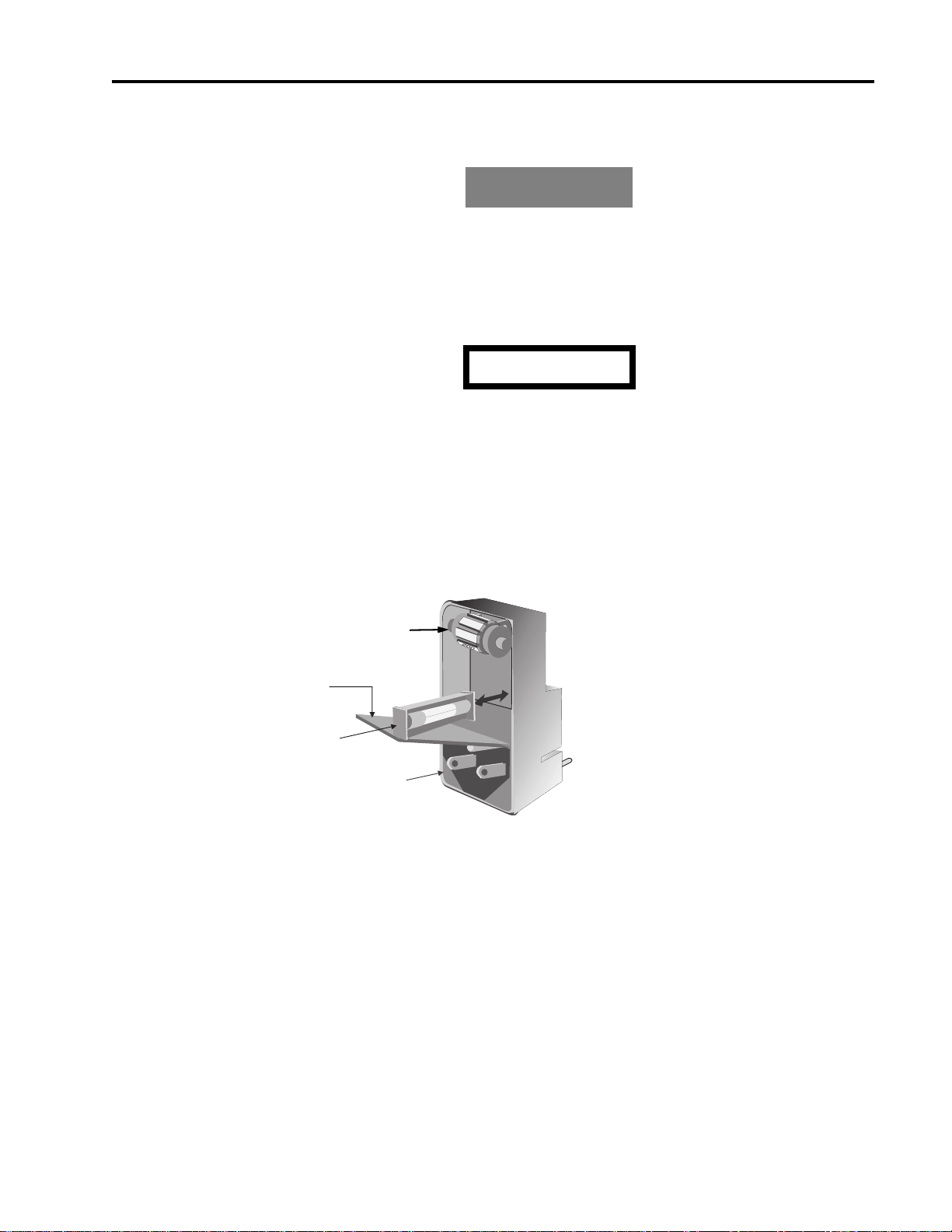
All 2500A Series models have a line fuse holder on the rear panel. The power line fuse is 2A, SlowBlow, 250V, Type T. See Figure 1-1 below for the location of the line fuse.
Not Used
COVER
FUSE AND
FUSE HOLDER
AC POWER
INPUT
Figure 1-1: Fuse Holder
1.2.5.1 Line Fuse Replacement
Open the housing cover. Pull out the small drawer on the right side of the housing (marked with an
arrow) and remove the old fuse. Replace with a new fuse, insert the drawer and close the housing cover,
see Figure 1-1, above.
1
1
0
1
2
0
2500A Series Operation Manual, 34172 Revision C, March 2008

Chapter 1: 2500A Introduction
NOTE: The voltage select wheel shown in Figure 1-1, above, can be set at any position. Its position
has no effect on the 2500A line voltage, as the 2500A line voltage is auto-sensing and autosetting.
1.2.6 Calibration Cycle
Giga-tronics recommends a calibration cycle of two years for the 2500A.
1.2.7 Reshipment Preparation
If it is necessary to return the instrument to the factory, protect it during reshipment using the best packaging materials available. If possible, reuse the original shipping container. If the original shipping container is not available, use a strong carton (350lbs./ sq.in. bursting strength) or a wooden box. Wrap the
instrument in heavy paper or plastic before placing it into the shipping container. Completely fill the
areas on all sides of the instrument with packaging material. Take extra precaution to protect the front
and rear panels. Seal the package with strong tape or metal bands. Mark the outside of the package as follows:
FRAGILE - DELICATE INSTRUMENT
If corresponding with the factory or local Giga-tronics sales office regarding reshipment, please provide
the model and serial number. If the instrument is being returned for repair, be sure to enclose all relevant
information regarding the problem that has been found.
NOTE: If returning an instrument to Giga-tronics for service, first contact Customer Service so that a
return authorization number (RMA) can be assigned. Contact Giga-tronics via email
(repairs@gigatronics.com) or by phone (800.726.4442). The 800 number is only valid within
in the United States. Contact can also occur via our domestic line at (925.328.4640) or Fax at
(925.328.4702).
1.3 Inputs and Outputs
The input and output connectors are shown in figures 1-2 and 1-3. Table 1-3 contains the front and rear
panel I/O connector functional descriptions for all 2500A Series models.
18 2500A Series Operation Manual, 34172 Revision C, March 2008
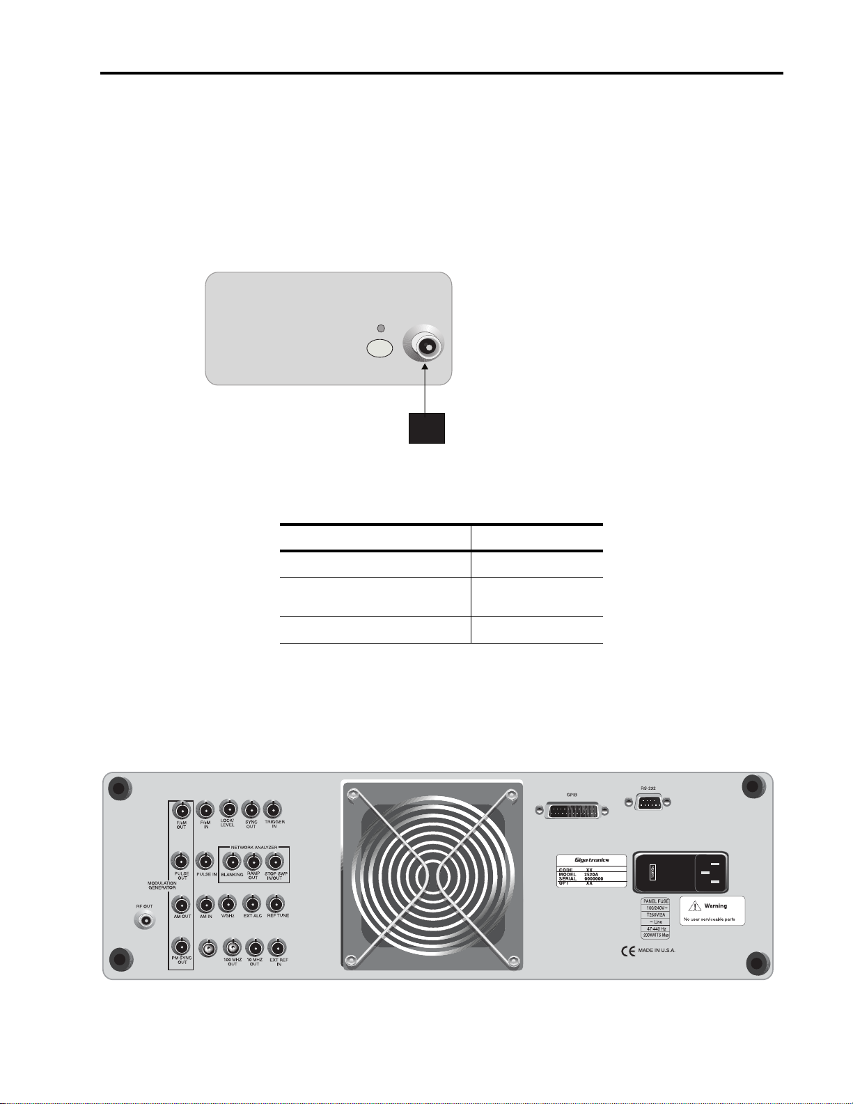
1.3.1 Front Panel Connector (RF Output)
This is the instrument’s RF output. It is located on the front panel of 2500B Series Synthesizer models,
and on the rear panel of versions of 2500S Series models.
The type of RF connector that is supplied depends on the frequency range of the instrument. Figure 1-2
shows the general location of the front panel RF output connector on 2500B Series models, and
Table 1-2 indicates by model the type of RF connector that is supplied.
RF
ON
RF OUT
Figure 1-2: Series 2500B Front Panel Output
ALC IN
Inputs and Outputs
Table 1-2: RF Connector Types
Models RF Connector Type
2508A/2508AS N (f)
2520A/2520AS
2526A/2526AS
2540A/2540AS K (f)
SMA (f)
1.3.2 Rear Panel Interface and I/O Connectors
This section defines the functions of the 2500A Series rear panel connectors (see Figure 1-3).
2500A Series Operation Manual, 34172 Revision C, March 2008

Chapter 1: 2500A Introduction
Figure 1-3: 2500A Rear Panel
All rear panel I/O connectors explained in this section are type BNC unless otherwise stated. Some connectors may not be supported because of installed options. For example, Modulation and Modulation
Generator connectors are not active with Option 17A or 17B. Table 1-3 describes the 2500A rear panel
I/O connectors.
Table 1-3: 2500A Rear Panel I/O Connector Descriptions
Connector Label Description
EXT ALC In external leveling, the output of the 2500B is detected by either a positive or negative
crystal detector or power meter with an analog output. The signals from these devices
are connected to the ALC circuitry of the 2500B which is used to compensate for
standing wave effects or cable and component losses at the input of the device under
test.
See Section 4.2.8 for External ALC specifications
RF OUT The RF signal output for the instrument. See Table 1-2 for RF connector types.
It is located on the front panel for all 2500B Series instruments and rear panel for all
2500S Series instruments.
FM OUT
1
The internal modulation generator output;
2 Vp-p into 10k Ω.
PULSE OUT
AM OUT
1
1
A +4V video representation of the pulsed RF output signal.
The internal modulation generator output;
2 Vp-p into 10k Ω.
PM SYNC OUT
1
A synchronization output pulse of >75 ns width, TTL level that can be delayed relative
to the leading edge of the video signal at the PULSE OUT connector.
2
FM IN
A 50 Ω input for an external FM signal. The input signal can be any waveform
compatible within bandwidth considerations. A 1 Vp input produces maximum
deviation.
An externally supplied DC signal can be applied to modulate the frequency of the CW
output using this connector.
See Section 4.2.6 for DC FM specifications
AM IN
2
A 600 Ω input for an external AM signal. The input signal can be any waveform
compatible within bandwidth considerations. A 1 Vp-p input produces 50% AM depth.
PULSE IN/PM TRIG IN2A Pulse Modulation Input for external pulse gating, pulse triggering or external Pulse In.
The input parameters are +5 volt, 50 Ω
LOCK/LEVEL +5 volt indicator, active high when the 2500A is phase locked and output leveled. The
Lock and Level indicator is valid for CW mode only.
REF TUNE A 0 to +10 volts, high impedance input for tuning the internal reference for adjusting the
output frequency approximately +
5 ppm. Do not exceed +15 volts or apply a negative
voltage greater than -1 volt.
SYNC OUT In List mode, the unit can be set to generate a pulse at this output when a specified list
point is reached. The output can be delayed from the start of the list point up to a
maximum of 10 msec. The pulse width of the SYNC OUT signal is determined by the
following parameters: pulse width = Step Time - Sync Delay - 10 usec
In Ramp operation, the pulse occurs at the start of each ramp sweep.
In either case, the output pulse is +5 volt.
20 2500A Series Operation Manual, 34172 Revision C, March 2008

Inputs and Outputs
Table 1-3: 2500A Rear Panel I/O Connector Descriptions
Connector Label Description
TRIGGER IN Used to trigger a List. Accepts a TTL level signal of > 50 ns width.
BLANKING A +5 volt output signal occurring at band crossings, filter switches, and retraces for the
duration of those events.
RAMP OUT A 0 to 10 volt ramp output scaled to the frequency sweep.
STOP SWP IN/OUT Stop Sweep I/O is a 5 volt, 2 K Ω, active low signal that temporarily interrupts an
instrument frequency or power ramp sweep. This feature is only available with 2500B
models with option 55 and 2500S models with options 55 and 44.
V/GHz An output voltage that is directly proportional to output frequency. For 26 and 40 GHz
models, the output is 0.25 volts per GHz. For 8 and 20 GHz models, the output is 0.5
volts per GHz.
100 MHz OUT A +5 dBm typical, AC coupled, 100 MHz low noise reference output signal into 50 Ω
10 MHz OUT A 2 Vp-p 10 MHz square wave reference output signal into 50 Ω.
EXT REF IN The external reference input. Can be either a 10 MHz input that is >-5.0 dBm into 50 Ω
or a 100 MHz input > +5 dBm. The 100 MHz input level should not exceed +8 dBm for
best performance.
GPIB A 24-pin IEEE STD 488.2 connector for control of the instrument during remote
operation using GPIB.
RS-232 A DB-9 connector for control of the instrument during remote operation using RS-232
serial communications.
AC Power Input 90-253 VAC, auto-sensing, 47 Hz to 440 Hz.
1. Not available with Option 17A or 17B.
2. Not available with Option 17A
.
2500A Series Operation Manual, 34172 Revision C, March 2008

Chapter 1: 2500A Introduction
22 2500A Series Operation Manual, 34172 Revision C, March 2008

Front Panel Operation
2
2.1 Introduction
This chapter describes how to operate the 2500A Series from the front panel.
The information in this chapter pertains primarily to the 2500A Series of Gigatronics Microwave Synthesizers. Note, however, that while the menus, key sequences, etc., presented in this chapter pertain primarily to front panel operation, the features explained are universal for either the front panel or remote
operating modes.
NOTE: Chapter 3 provides instructions on using the 2500A Series from a remote host computer over
the General Purpose Interface Bus (GPIB), an RS-232 serial connection, USB or Ethernet.
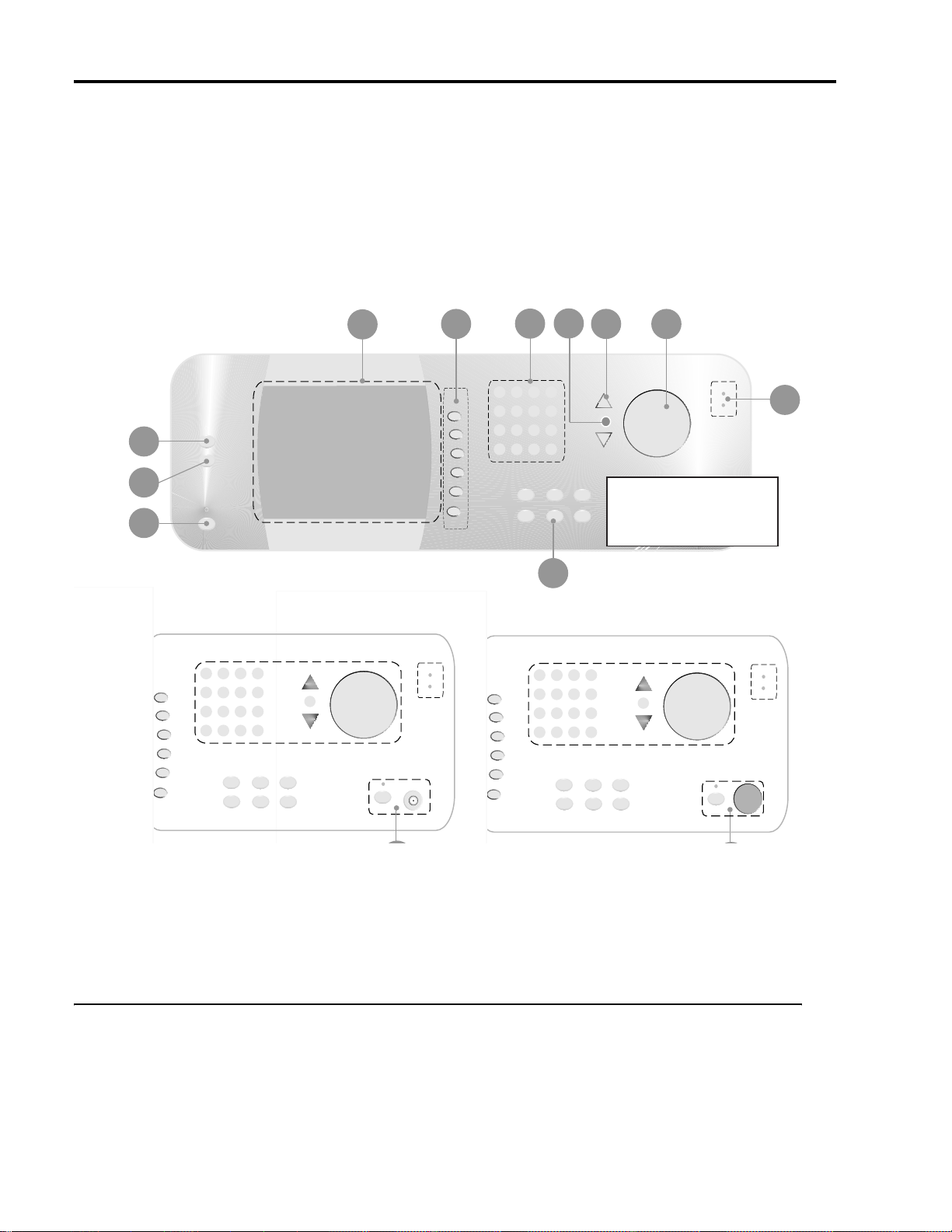
2.2 Front Panel At a Glance
The 2500A Series front panel contains the controls and display for local operation of the instrument.
Some functions are not available from the front panel; they require use of a PC with a compatible remote
interface. Front panel controls are grouped according to the functions they perform. Descriptions for the
front panel controls are referenced to the numbers depicted in Figure 2-1 on the next page.
2500A Series Operation Manual, 34172 Revision C, March 2008
Chapter 2: Front Panel Operation
4
5
6
8
7
9
10
3
2
1
Microwave Synthesizers
Bottom Sectional Differential
See A for 2500A Series
See B for 2500AS S eries
12
Front Panel Layout of 2500 Series Microwave Synthesizers
Figure 2-1: 2500A Front Panel with Callouts
2.2.1 Front Panel Description
Power
The main power switch for the 2500A, which is used to set the power either to on or standby. A blue
indicator indicates that main power button is blue, an amber indicator indicates that the main power is off
but power is applied to the internal timebase oscillator.
24 2500A Series Operation Manual, 34172 Revision C, March 2008

LOCAL Button
1
PRESET Button
Front Panel At a Glance
Allows front panel access when the unit is in remote mode. If the unit is already in local mode, pressing
this button accesses menus that allow you to choose the remote command language to be used by the
instrument while remote operation.
Presets the 2500A to factory defaults, or initializes NVRAM.
2
3
Display
4
Interactive Softkeys
Data Entry Keypad
• Pressing the PRESET button momentarily presets instrument settings to factory default values, but
does not affect system memory locations, display contrast, or the GPIB address.
• Pressing and holding the PRESET button while the unit is powering up initializes NVRAM, which
includes presetting instrument settings to factory default values as well as initializing all ten system
memory locations, the display contrast, and the GPIB address.
Displays current instrument settings, as well as the menus that allow you to modify the settings. The
group of instrument settings and associated menu items that are currently displayed is called the active
display.
Menus are accessed by pressing the menu buttons. The menus appear along the right-hand side of the display adjacent to the interactive softkeys. To select a particular menu item, press the adjacent interactive
softkey. Modify the parameter using the data entry keypad, step-up/step-down buttons, or knob.
Selects the menu items adjacent to them in the display for modification.
A 12-button numeric keypad and adjacent Units buttons for direct entry of instrument parameters.
STEP SIZE Button
5
Selects and allows editing of the step size used by the Step Up/Down buttons and rotary knob. To change
a step size, choose a menu item, press the STEP SIZE button, enter the step size using the keypad, then
press the appropriate units button.
6
Step Up/Down Buttons
Increases or decreases the selected parameter in the display by the amount specified by the step size.
7
Rotary Knob
Increases or decreases the parameter that is selected in the display. When a maximum or minimum limit
is reached, a message will be displayed at the bottom of the display indicating that the parameter limit
has been reached.
8
Front Panel LED indicators
The front panel indicators are located in several places.
2500A Series Operation Manual, 34172 Revision C, March 2008

Chapter 2: Front Panel Operation
9
10
RF Output
Menu Buttons
11
Unleveled Indicator. This indicator is lit when the 2500A output is operating in an unleveled state.
External Reference (Ext Ref) Indicator. This indicator is lit when the 2500A is operating with an
external reference applied.
RF On/Off Indicator. This indicator, which is located above the RF ON button, is blue when the 2500A
RF output is active. When the RF output is inactive, the indicator is not lit.
Power Indicator. This indicator, which is above the main power button, is blue when the unit is on, and
amber when the unit is in standby mode.
This is the RF output section for 2500A Series instruments. The 2500A series connector is located on the
lower left portion of the front panel.
CW Button. Pressing this button displays the CW Menu, which shows parameters related to the CW
functions of the instrument, and the Cable Correction functions and their associated menu items.
RAMP Button. Pressing this button displays either the Ramp Freq or Ramp Power Menu, which shows
parameters related to either the frequency or power ramp (sweep) functions of the instrument, and their
associated menu items.
SYSTEM Button. Pressing this button displays either the System 1 or System 2 Menu, which shows
parameters related to certain system-level functions, and their associated menu items.
12
AM Button. Amplitude modulation is not available on the 2500A.
FM Button. Frequency Modulation is not available on the 2500A.
PM Button. Pressing this button displays the External PM Menu which shows parameters related to the
pulse modulation functions of the instrument, and their associated menu items.
2.3 2500A Menus
This section provides a brief overview of the 2500A’s display and menus, and explains each of the
2500A menus in more detail.
26 2500A Series Operation Manual, 34172 Revision C, March 2008
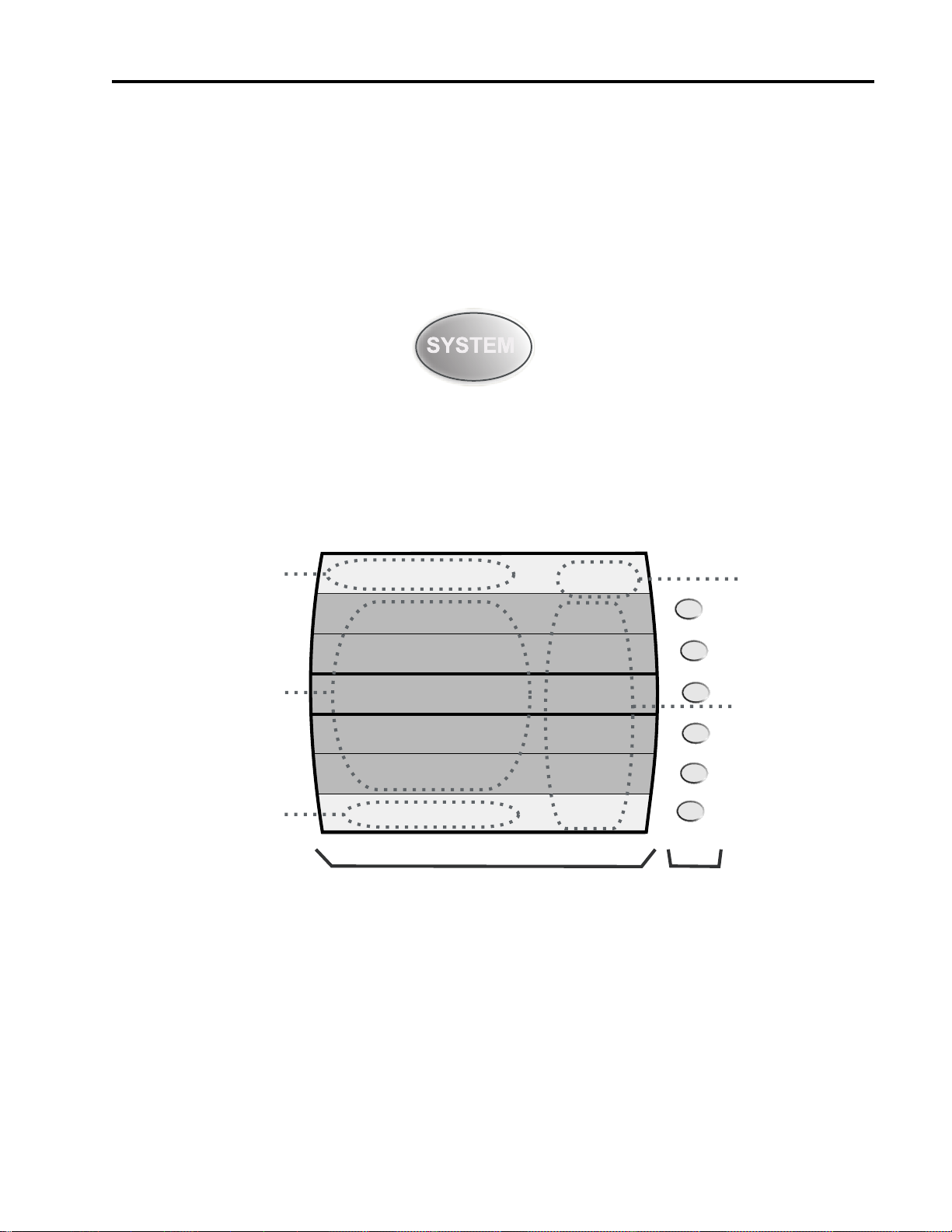
2.3.1 Menu System Overview
SYSTEM 1
OFS SLP
To Register (0-9)
No register has been saved
8
ON
Save
Recall
Sound
Contrast
Auto
Attenuation
System 2
Menu
AM FM PM
Contrast must be <= 15
Menu Area
Mode Indicators
Menu Name
Parameter Area
Error/Step Size Area
Display
Interactive
Softkeys
2.3.1.1 Menu Buttons
Most 2500A features and functions are accessed through a series of menus. The menus are accessed by
pressing one of the menu buttons that are on the front panel of the instrument. As an example, to access
the System menus, press the SYSTEM button:
The following menu buttons are available:
CW, RAMP, SYSTEM, PM, LOCAL.
2500A Menus
The 2500A’s front panel display is divided into several functional areas, as shown in Figure 2-2:
Figure 2-2: Functional Areas of the 2500A Display
The following explains each of the functional areas of the display shown in Figure 2-2:
Menu Name. This is the name of the menu that is currently shown in the front panel display. The menu
that is currently shown is called the active menu.
2500A Series Operation Manual, 34172 Revision C, March 2008
Menu Area. This area displays the various menu choices that are available in the active menu. The row
containing the menu item and parameter that is currently selected is surrounded by bold lines.

Chapter 2: Front Panel Operation
Parameter Area. This area displays the current values of the instrument settings that are associated with
the active menu. Parameters can be modified.
Error/Step Size Area. If applicable, this area shows the currently set step size for the parameter that is
selected for modification. Certain non-error user messages might also be displayed in this area.
Mode Indicators. Indicators will appear in this area of the display if the instrument is currently in any of
several operating modes. If the instrument is currently in a given operating mode, its indicator will
appear regardless of the menu that is currently active. The following indicators are available:
OFS - Appears if a power offset of greater than 0 dB is set in the CW menu.
SLP - Appears if a power slope of greater than 0 dB/GHz is set in the CW menu.
PM - Appears if either internal or external pulse modulation is currently enabled.
EXT. LEVEL - Appears if the ALC is set to External.
UNLK - Appears if the Phase Lock Loop is unlocked.
OVEN COLD - Appears if the internal temperature of the 2500A has not reached operational tem-
perature. It is not recommended to use the 2500A while this indicator is active.
2.3.2 CW Menu Descriptions
The CW menus display the instrument’s currently set CW (continuous wave) frequency, power level,
power offset, and power slope, and allows you to make changes to those settings. The Cable Cal menu
allows you to perform and a apply a cable offset correction to the CW menu power level setting. The
Cable Cal feature requires a Giga-tronics 8650A series power meter or any power meter with a SCPI
compatible command set. To access the CW menu, press the front panel CW menu button:
There are two menus associated with the CW menu button. Figure 2-3 shows the CW menu:
28 2500A Series Operation Manual, 34172 Revision C, March 2008

CW MENU
2500A Menus
6.00 GHz
3.21 dBm
0.00 dB
0.00 dB/GHz
0 Degrees
Step Size: 0.1 Hz
Frequency
Power
Power Offset
Power Slope
Phase
Cable Cal
Menu
Figure 2-3: CW Menu with Interactive Softkeys
The following explains each item in the CW menu:
Frequency. This menu item displays and allows you to modify the instrument’s CW frequency. The
range of the CW frequency parameter is dependent on the model number of the instrument.
Power. This menu item displays and allows you to modify the instrument’s output power level. The
range of the output power level depends on the following configuration and settings of the instrument:
Power Offset. This menu item displays and allows you to modify the instrument’s power offset. The
power offset feature increases the instrument’s output power by the amount of the power offset setting,
without changing the power level as shown in the Display. This allows you to compensate for the insertion or conversion loss of components that are attached to the instrument’s RF output. An example
appears in Figure 2-4.
2400LMicrowave Synthesizer
Power Level Setting = +10 dBm
Power Offset Setting = 2.23 dB
Figure 2-4: Power Offset Example
The Power Offset indicator (OFS) appears in the upper right-hand corner of the display when any power
offset value greater than 0.00 dB is entered.
Power Slope. This menu item displays and allows you to modify the instrument’s power slope. The
power slope feature increases the instrument’s output power linearly as a function of the output frequency. The power slope function allows you to automatically compensate for insertion/conversion
losses of components attached to the instrument’s RF output that exhibit a linear loss characteristic with
2500A Series Operation Manual, 34172 Revision C, March 2008
RF Mixer
×
Conversion Loss = 2.23 dB
+10 dBm is present
at the output of
the RF mixer
Chapter 2: Front Panel Operation
frequency. The Power Slope indicator (SLP) appears in the upper right-hand corner of the display when
any power slope value greater than 0.00 dB/GHz is entered.
Phase Adjust. This menu item displays and allows you to modify the phase of the output signal. The
phase of the signal is maintained until the phase is readjusted or whenever the instrument frequency setting is changed. When the instrument frequency setting is changed, the phase adjust setting is reset to 0
degrees. Phase Adjust is specified for a minimum frequency range of 500 MHz to the maximum frequency range of the instrument. Phase adjust is available for frequencies below 500 MHz however the
output response time of the phase adjust is decreased.
Specifications:
Frequency: 500 MHz to maximum frequency
Range:
Accuracy: <0.2
±360 degrees
°, typical
2.3.2.1 Cable Cal Menu
This menu allows you to generate an offset table for use with the power level setting in the CW menu
using the pre-selected power meter and RS-232 interface. Figure 2-5 shows the Cable Cal RS-232 menu.
A similar menu is displayed if an Agilent EPM power meter is selected.
Cable Cal: RS-232
Cable Cal Cleared
1. Connect NULL modem cable between 2400B & 8650A RS-232 ports
2. Connect BNC cable between 2400B Sync Out and 8650A Trig In
3 Connect calibrated sensor on 8650A Chan A to 2400B RF Out cable
4. Set 8650 RS232 baud rate to 38400 and press Start Cable Cal
Cable Cal sweeps from 10 MHz to 20 GHz.
Cable Cal Setup
Use appropriate sensor
Figure 2-5: Cable Cal RS-232 Menu
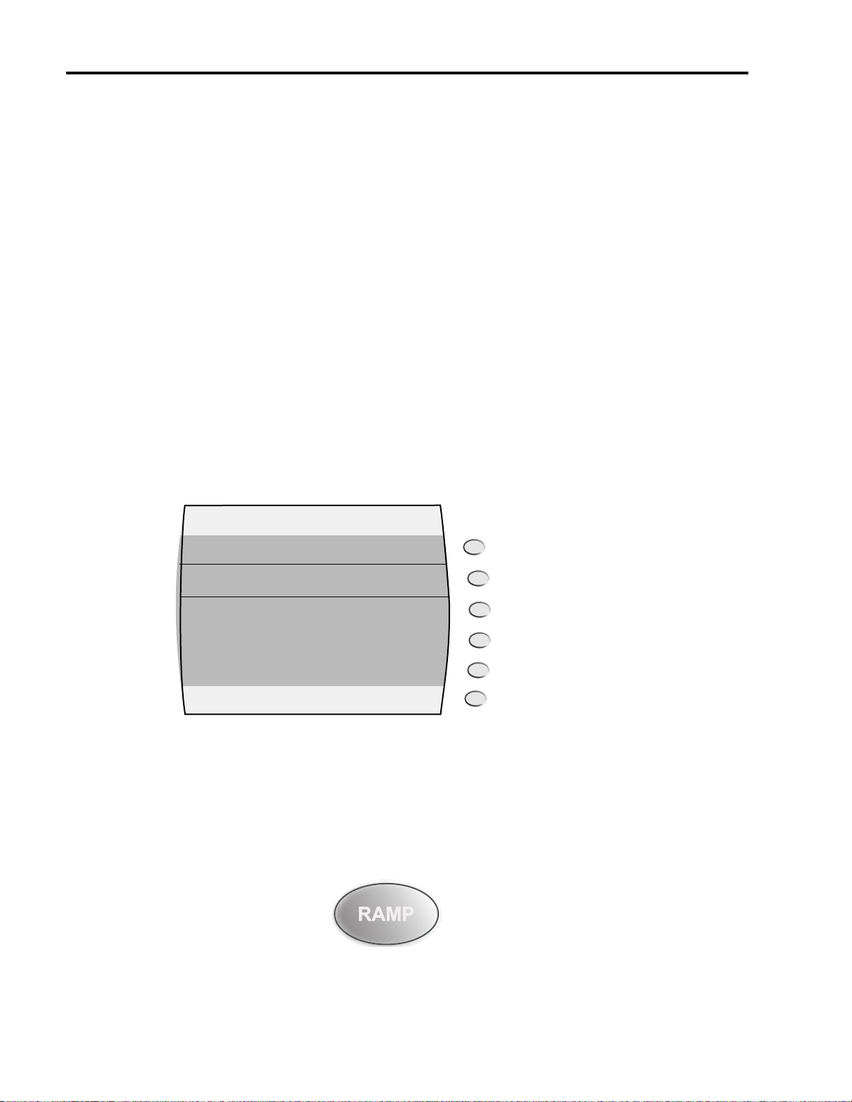
2.3.3 RAMP Menu Descriptions
The RAMP menus display the instrument’s currently set ramp frequency sweep and ramp power sweep
settings, and allow you to make changes to those settings.
Start
Cable Cal
Clear
Cable Cal
CW
Menu
There are 7 menus associated with the RAMP menu button. There is one top level menu that alllows
access to any of the 6 sweep function menus. Figure 2-6 shows the Sweep Main Menu.
30 2500A Series Operation Manual, 34172 Revision C, March 2008
 Loading...