

2500A Serie
s
2500A Series Microwave Synthesizer Operations Manual
34172, Revision C, March 2008

All technical data and specifications in this publication are subject to change without prior notice and do not
represent a commitment on the part of Giga-tronics, Incorporated.
© 2004 Giga-tronics Incorporated. All rights reserved. Printed in the USA.
WARRANTY
Giga-tronics 2500A Series instruments are
warranted against defective materials and
workmanship for four years from date of shipment.
Giga-tronics will at its option repair or replace
products that are proven defective during the
warranty period. This warranty DOES NOT cover
damage resulting from improper use, nor
workmanship other than Giga-tronics service.
There is no implied warranty of fitness for a
particular purpose, nor is Giga-tronics liable for any
consequential damages. Specification and price
change privileges are reserved by Giga-tronics.
MODEL NUMBERS
The 2500A Series has model numbers for each instrument with a specific frequency range as described in Chapter 1.
All models are referred to in this manual by the general term 2500A, except where it is necessary to make a
distinction between the models. In these cases, the specific model number(s) will be used.
Giga-tronics, Incorporated
4650 Norris Canyon Road
San Ramon, California 94583
TEL: 800.726.4442
925.328.4650
FAX: 925.328.4700
www.gigatronics.com

Declaration of Conformity
Application of Council Directive(s)
Standard(s) to which Conformity is Declared:
89/336/EEC and 73/23/EEC EMC Directive and Low Voltage Directive
EN61010-1 (1993) Electrical Safety
EN61326-1 (1997) EMC - Emissions & Immunity
Manufacturer’s Name: Manufacturer’s Address:
Giga-tronics, Incorporated 4650 Norris Canyon Road
San Ramon, California 94583
U.S.A.
Type of Equipment: Model Series Number:
Microwave Synthesizer 2500A Series
Model Numbers In Series:
2508A, 2520A, 2526A, 2540A
2508AS, 2520AS, 2526AS, 2540AS
Declaration of Conformity on file. Contact Giga-tronics, Inc.
4650 Norris Canyon Rd.
San Ramon, CA 94583
Ph: 1-925-328-4650
Fx: 1-925-328-4700


About The Publication
Preface
This publication provides an overview and describes local (front panel) operation, remote operation,
specifications, and performance verification of the Giga-tronics 2500A family of Microwave Synthesizers. This Preface contains chapter descriptions, a record of changes made to the publication since its production, and a description of the special configurations. Changes that occur after production of this
publication, and Special Configuration data will be inserted as loose bound pages in the publication
binder. Please insert and/or replace the indicated pages as detailed in the Technical Publication Instructions included with new and/or replacement pages.
Chapters:
1- Introduction
This chapter contains an overview of the 2500A, basic system information, and input and output descriptions.
2 - Front Panel Operation
This chapter contains information about front panel operation of the instrument. Controls, features, and
menus are described, operating tasks are explained, and factory default settings are listed.
3- Remote Operation
This chapter contains information about remote operation of the instrument over the General Purpose
Interface Bus (GPIB) or RS-232.
4- Specifications & Performance Verification
This chapter contains 2500A specifications and step-by-step procedures to verify 2500A Series Microwave Synthesizer performance.
Appendices:
A- Accessories and Options
This appendix describes the accessories and options that are available for the 2500A Series Microwave
Synthesizers. Each accessory and option is described under its respective heading.
B - Error Messages
This appendix provides a description of the various error messages and other user messages that might be
encountered during instrument operation.
Index
A subject listing of contents.
2500A Series Operation Manual, 34172 Revision C, March 2008

Conventions
The following safety conventions are used in this publication. Additional conventions not included here are
defined at the time of usage.
Warning
WARNING
The WARNING statement is encased in gray and centered in the page. This calls
attention to a situation, or an operating or maintenance procedure or practice, which if
not strictly corrected or observed, could result in injury or death of personnel. An
example is the proximity of high voltage.
Caution
CAUTION
The CAUTION statement is enclosed with single lines and centered in the page. This
calls attention to a situation, or an operating or maintenance procedure, or practice,
which if not strictly corrected or observed, could result in temporary or permanent
damage to the equipment, or loss of effectiveness.
Notes
NOTE: A NOTE Highlights or amplifies an essential operating or maintenance procedure, practice,
condition or statement.
6 2500A Series Operation Manual, 34172 Revision C, March 2008

Configuration Data
Giga-tronics: Serial, Code, Models, Option or Configuration Label
Examine the code, model number, serial number, and option/configuration label affixed to the rear panel of the
2500A Microwave Synthesizer.
Code Number
Each instrument has a two-digit code, referred to as the Manufacturing Configuration Code.
Model Number
Each instrument has a four-digit model number in the form 25XX, and one or two character suffix which designates the series:
- 25XXB - Benchtop model
- 25XXS - ATE model
The frequency range of the instrument is designated by the model number:
- 2508A - 0.1 MHz to 8 GHz
- 2520A - 0.1 MHz to 20 GHz
- 2526A - 0.1 MHz to 26.5 GHz
- 2540A - 0.1 MHz to 40 GHz
Serial Number
Each instrument has a seven-digit serial number, shown on the label of the rear panel.
Option Number(s)
When options are installed, one or more 2 digit numbers are listed on the “Opt.” line and correspond to
options installed in the instrument. Option numbers are explained in Appendix A.
Special Configurations
When the accompanying product has been configured for user-specific application(s), supplemental pages will
be inserted at the front of the publication binder. Remove the indicated page(s) and replace it (them) with the
furnished Special Configuration supplemental page(s).
If the “Opt.” line contains a three digit number (for example, 641), there is combination of options and/or special modifications installed in the instrument. Information relating to these special configurations is contained
in supplemental pages included with the manual.
2500A Series Operation Manual, 34172 Revision C, March 2008

Record of Publication
Changes
This table is provided for your convenience to maintain a permanent record of publication change data.
Replacement pages will be issued as a TPCI (Technical Publication Change Instruction), and will be
inserted at the front of the binder. Remove the corresponding old pages, insert the new pages, and
record the changes here.
TCPI Number TPCI Issue Date Date Entered Comments
8 2500A Series Operation Manual, 34172 Revision C, March 2008

CHAPTER 1: 2500A INTRODUCTION
1.1 Overview. . . . . . . . . . . . . . . . . . . . . . . . . . . . . . . . . . . . . . . . . . . . . . . . . . 13
1.1.1 2500A Frequency Ranges . . . . . . . . . . . . . . . . . . . . . . . . . . . . . . . 13
1.1.2 2500A Options . . . . . . . . . . . . . . . . . . . . . . . . . . . . . . . . . . . . . . . . 14
1.1.3 Items Furnished . . . . . . . . . . . . . . . . . . . . . . . . . . . . . . . . . . . . . . . 14
1.1.4 Items Required . . . . . . . . . . . . . . . . . . . . . . . . . . . . . . . . . . . . . . . . 14
1.2 General Information . . . . . . . . . . . . . . . . . . . . . . . . . . . . . . . . . . . . . . . . 15
1.2.1 Receiving Inspection . . . . . . . . . . . . . . . . . . . . . . . . . . . . . . . . . . . 15
1.2.2 Cooling. . . . . . . . . . . . . . . . . . . . . . . . . . . . . . . . . . . . . . . . . . . . . . 15
1.2.3 Cleaning . . . . . . . . . . . . . . . . . . . . . . . . . . . . . . . . . . . . . . . . . . . . . 15
1.2.4 Power . . . . . . . . . . . . . . . . . . . . . . . . . . . . . . . . . . . . . . . . . . . . . . . 15
1.2.5 Line Fuse . . . . . . . . . . . . . . . . . . . . . . . . . . . . . . . . . . . . . . . . . . . . 17
1.2.6 Calibration Cycle . . . . . . . . . . . . . . . . . . . . . . . . . . . . . . . . . . . . . . 18
1.2.7 Reshipment Preparation . . . . . . . . . . . . . . . . . . . . . . . . . . . . . . . . . 18
1.3 Inputs and Outputs . . . . . . . . . . . . . . . . . . . . . . . . . . . . . . . . . . . . . . . . . 18
1.3.1 Front Panel Connector (RF Output). . . . . . . . . . . . . . . . . . . . . . . . 19
1.3.2 Rear Panel Interface and I/O Connectors. . . . . . . . . . . . . . . . . . . . 19
Table of Contents
1.2.5.1 Line Fuse Replacement . . . . . . . . . . . . . . . . . . . . . . . . . . . . . 17
CHAPTER 2: FRONT PANEL OPERATION
2.1 Introduction . . . . . . . . . . . . . . . . . . . . . . . . . . . . . . . . . . . . . . . . . . . . . . . 23
2.2 Front Panel At a Glance . . . . . . . . . . . . . . . . . . . . . . . . . . . . . . . . . . . . . 23
2.2.1 Front Panel Description . . . . . . . . . . . . . . . . . . . . . . . . . . . . . . . . . 24
2.3 2500A Menus . . . . . . . . . . . . . . . . . . . . . . . . . . . . . . . . . . . . . . . . . . . . . . 26
2.3.1 Menu System Overview. . . . . . . . . . . . . . . . . . . . . . . . . . . . . . . . . 27
2.3.1.1 Menu Buttons . . . . . . . . . . . . . . . . . . . . . . . . . . . . . . . . . . . . 27
2.3.2 CW Menu Descriptions . . . . . . . . . . . . . . . . . . . . . . . . . . . . . . . . . 28
2.3.2.1 Cable Cal Menu. . . . . . . . . . . . . . . . . . . . . . . . . . . . . . . . . . . 30
2.3.3 RAMP Menu Descriptions. . . . . . . . . . . . . . . . . . . . . . . . . . . . . . . 30
2.3.3.1 Ramp Freq 1 Menu . . . . . . . . . . . . . . . . . . . . . . . . . . . . . . . . 31
2.3.3.2 Ramp Freq 2 Menu . . . . . . . . . . . . . . . . . . . . . . . . . . . . . . . . 32
2.3.3.3 Ramp Power Menu . . . . . . . . . . . . . . . . . . . . . . . . . . . . . . . . 33
2.3.3.4 Step Sweep Freq Menu . . . . . . . . . . . . . . . . . . . . . . . . . . . . . 34
2.3.4 SYSTEM Menu Descriptions . . . . . . . . . . . . . . . . . . . . . . . . . . . . 36
2.3.4.1 System 1 Menu . . . . . . . . . . . . . . . . . . . . . . . . . . . . . . . . . . . 36
2.3.4.2 System 2 Menu . . . . . . . . . . . . . . . . . . . . . . . . . . . . . . . . . . . 38
2.3.4.3 System Menu 3 . . . . . . . . . . . . . . . . . . . . . . . . . . . . . . . . . . . 39
2.3.4.4 System Menu 4 . . . . . . . . . . . . . . . . . . . . . . . . . . . . . . . . . . . 39
2500A Series Operation Manual, 34172 Revision C, March 2008
9

2.3.5 AM Menu Descriptions . . . . . . . . . . . . . . . . . . . . . . . . . . . . . . . . . 40
2.3.5.1 External AM Menu . . . . . . . . . . . . . . . . . . . . . . . . . . . . . . . . 40
2.3.5.2 AM - Internal Waveform . . . . . . . . . . . . . . . . . . . . . . . . . . . 41
2.3.5.3 AM - Internal Noise . . . . . . . . . . . . . . . . . . . . . . . . . . . . . . . 42
2.3.6 FM Menu Descriptions . . . . . . . . . . . . . . . . . . . . . . . . . . . . . . . . . 43
2.3.6.1 FM - External Menu . . . . . . . . . . . . . . . . . . . . . . . . . . . . . . . 44
2.3.6.2 FM - Internal Menu. . . . . . . . . . . . . . . . . . . . . . . . . . . . . . . . 44
2.3.6.3 DC FM Menu . . . . . . . . . . . . . . . . . . . . . . . . . . . . . . . . . . . . 45
2.3.7 PM Menu Descriptions . . . . . . . . . . . . . . . . . . . . . . . . . . . . . . . . . 46
2.3.7.1 PM - External Source Menu . . . . . . . . . . . . . . . . . . . . . . . . . 47
2.3.7.2 PM Internal-Continuous Menu . . . . . . . . . . . . . . . . . . . . . . . 47
2.3.7.3 PM Internal-Gated Menu . . . . . . . . . . . . . . . . . . . . . . . . . . . 49
2.3.7.4 PM Internal-Triggered Menu . . . . . . . . . . . . . . . . . . . . . . . . 50
2.3.8 Language Menu Descriptions . . . . . . . . . . . . . . . . . . . . . . . . . . . . 52
2.3.8.1 Language Menu 1 . . . . . . . . . . . . . . . . . . . . . . . . . . . . . . . . . 52
2.3.8.2 Language Menu 2 . . . . . . . . . . . . . . . . . . . . . . . . . . . . . . . . . 53
2.3.8.3 Language Menu 3 . . . . . . . . . . . . . . . . . . . . . . . . . . . . . . . . . 54
2.4 Front Panel Operating Tasks . . . . . . . . . . . . . . . . . . . . . . . . . . . . . . . . . 55
2.4.1 Power-Up. . . . . . . . . . . . . . . . . . . . . . . . . . . . . . . . . . . . . . . . . . . . 55
2.4.1.1 Normal Power-Up. . . . . . . . . . . . . . . . . . . . . . . . . . . . . . . . . 55
2.4.1.2 Errors During Power-Up. . . . . . . . . . . . . . . . . . . . . . . . . . . . 57
2.4.2 Basic Operating Tasks . . . . . . . . . . . . . . . . . . . . . . . . . . . . . . . . . . 57
2.4.2.1 Resetting the System/Sanitization Procedure . . . . . . . . . . . . 57
2.4.2.2 Entering and Modifying Parameters . . . . . . . . . . . . . . . . . . . 57
2.4.3 Signal Generation . . . . . . . . . . . . . . . . . . . . . . . . . . . . . . . . . . . . . 59
2.4.3.1 Generating a CW Signal . . . . . . . . . . . . . . . . . . . . . . . . . . . . 59
2.4.3.2 Generating an External ALC Leveled Signal . . . . . . . . . . . . 60
2.4.3.3 Using the Ref Tune Feature . . . . . . . . . . . . . . . . . . . . . . . . . 62
2.4.3.4 Cable Correction Function . . . . . . . . . . . . . . . . . . . . . . . . . . 63
2.4.3.4 Required Equipment . . . . . . . . . . . . . . . . . . . . . . . . . . . . . . . . . . 63
2.4.3.5 Configuring the 8650A Universal Power Meter . . . . . . . . . . 64
2.4.3.6 Configuring the Cable Correction Setup. . . . . . . . . . . . . . . . 64
2.4.3.7 Generating a Frequency Swept Signal . . . . . . . . . . . . . . . . . 65
2.4.3.8 Generating a Power Swept Signal. . . . . . . . . . . . . . . . . . . . . 65
2.4.3.9 Generating an Externally Pulse Modulated Signal . . . . . . . . 66
2.4.4 Remote Setup. . . . . . . . . . . . . . . . . . . . . . . . . . . . . . . . . . . . . . . . . 68
2.4.4.1 Setting the GPIB Address . . . . . . . . . . . . . . . . . . . . . . . . . . . 68
2.4.4.2 Selecting the Remote Language . . . . . . . . . . . . . . . . . . . . . . 68
CHAPTER 3: REMOTE OPERATION
3.1 Introduction . . . . . . . . . . . . . . . . . . . . . . . . . . . . . . . . . . . . . . . . . . . . . . . 69
10 2500A Series Operation Manual, 34172 Revision C, March 2008

3.1.1 What is Automation Xpress? . . . . . . . . . . . . . . . . . . . . . . . . . . . . . 69
3.1.2 Computer Interfaces. . . . . . . . . . . . . . . . . . . . . . . . . . . . . . . . . . . . 70
3.2 SCPI Command Set. . . . . . . . . . . . . . . . . . . . . . . . . . . . . . . . . . . . . . . . . 71
3.2.1 SCPI Command Format. . . . . . . . . . . . . . . . . . . . . . . . . . . . . . . . . 71
3.2.2 SCPI Command Subsystems . . . . . . . . . . . . . . . . . . . . . . . . . . . . . 72
3.2.2.1 Output Subsystem . . . . . . . . . . . . . . . . . . . . . . . . . . . . . . . . . 72
3.2.2.2 Source Subsystem - CW Mode . . . . . . . . . . . . . . . . . . . . . . . 72
3.2.2.3 Source Subsystem - Correction. . . . . . . . . . . . . . . . . . . . . . . 73
3.2.2.4 Source Subsystem - List Mode . . . . . . . . . . . . . . . . . . . . . . . 73
3.2.2.5 Status Subsystem. . . . . . . . . . . . . . . . . . . . . . . . . . . . . . . . . . 75
3.2.2.6 System Subsystem. . . . . . . . . . . . . . . . . . . . . . . . . . . . . . . . . 75
3.2.2.7 Trigger Subsystem. . . . . . . . . . . . . . . . . . . . . . . . . . . . . . . . . 76
3.2.2.8 Source Subsystem - Ramp Sweep. . . . . . . . . . . . . . . . . . . . . 77
3.2.2.9 Source Subsystem- Modulation . . . . . . . . . . . . . . . . . . . . . . 78
3.3 IEEE 488.2 Common Commands . . . . . . . . . . . . . . . . . . . . . . . . . . . . . 81
3.4 2500A Specific Commands . . . . . . . . . . . . . . . . . . . . . . . . . . . . . . . . . . . 82
3.5 Status Register System . . . . . . . . . . . . . . . . . . . . . . . . . . . . . . . . . . . . . . 83
3.5.1 Status Byte (STB) and Service Request Enable (SRE)
Registers . . . . . . . . . . . . . . . . . . . . . . . . . . . . . . . . . . . . . . . . 84
3.5.2 Standard Event Status (ESR) and Standard Event Status
Enable (ESE) Registers. . . . . . . . . . . . . . . . . . . . . . . . . . . . . 84
3.5.3 Questionable Status Condition and Enable Registers . . . . . . . . . . 85
3.5.4 List Mode Operation . . . . . . . . . . . . . . . . . . . . . . . . . . . . . . . . . . . 86
3.5.4.1 Example: List Mode . . . . . . . . . . . . . . . . . . . . . . . . . . . . . . . 86
CHAPTER 4: SPECIFICATIONS & PERFORMANCE VERIFICATION
4.1 Models. . . . . . . . . . . . . . . . . . . . . . . . . . . . . . . . . . . . . . . . . . . . . . . . . . . . 89
4.2 Specifications . . . . . . . . . . . . . . . . . . . . . . . . . . . . . . . . . . . . . . . . . . . . . . 89
4.2.1 Frequency. . . . . . . . . . . . . . . . . . . . . . . . . . . . . . . . . . . . . . . . . . . . 89
4.2.1.1 Frequency Bands . . . . . . . . . . . . . . . . . . . . . . . . . . . . . . . . . . 90
4.2.2 Output Power . . . . . . . . . . . . . . . . . . . . . . . . . . . . . . . . . . . . . . . . . 91
4.2.3 Spectral Purity . . . . . . . . . . . . . . . . . . . . . . . . . . . . . . . . . . . . . . . . 92
4.2.4 List Mode . . . . . . . . . . . . . . . . . . . . . . . . . . . . . . . . . . . . . . . . . . . . 93
4.2.5 Amplitude Modulation. . . . . . . . . . . . . . . . . . . . . . . . . . . . . . . . . . 94
4.2.6 Frequency Modulation . . . . . . . . . . . . . . . . . . . . . . . . . . . . . . . . . . 94
4.2.7 Pulse Modulation . . . . . . . . . . . . . . . . . . . . . . . . . . . . . . . . . . . . . . 94
4.2.8 External ALC . . . . . . . . . . . . . . . . . . . . . . . . . . . . . . . . . . . . . . . . . 95
4.2.9 Internal Modulation Generator. . . . . . . . . . . . . . . . . . . . . . . . . . . . 96
4.2.10 General Specifications . . . . . . . . . . . . . . . . . . . . . . . . . . . . . . . . 97
4.3 Performance Verification . . . . . . . . . . . . . . . . . . . . . . . . . . . . . . . . . . . . 98
4.3.1 Recommended Equipment . . . . . . . . . . . . . . . . . . . . . . . . . . . . . . . 98
2500A Series Operation Manual, 34172 Revision C, March 2008
11

4.3.2 Performance Tests: All 2500A Series . . . . . . . . . . . . . . . . . . . . . . 99
4.3.2.1 Frequency Range, Resolution & Accuracy. . . . . . . . . . . . . . 99
4.3.2.2 Spectral Purity Tests . . . . . . . . . . . . . . . . . . . . . . . . . . . . . . . 100
4.3.2.3 RF Output Power Tests. . . . . . . . . . . . . . . . . . . . . . . . . . . . . 101
4.3.3 Performance Tests: 2500A Series . . . . . . . . . . . . . . . . . . . . . . . . . 104
4.3.3.1 Amplitude Modulation Tests . . . . . . . . . . . . . . . . . . . . . . . . 104
4.3.3.2 Frequency Modulation Tests. . . . . . . . . . . . . . . . . . . . . . . . . 107
4.3.3.3 Pulse Modulation Tests. . . . . . . . . . . . . . . . . . . . . . . . . . . . . 109
4.3.3.4 Internal Modulation Generator Tests . . . . . . . . . . . . . . . . . . 114
4.3.4 2500A Series Test Datasheets . . . . . . . . . . . . . . . . . . . . . . . . . . . . 116
APPENDIX A: ACCESSORIES & OPTIONS
A.1 Introduction . . . . . . . . . . . . . . . . . . . . . . . . . . . . . . . . . . . . . . . . . . . . . . 123
A.2 List of Accessories and Options. . . . . . . . . . . . . . . . . . . . . . . . . . . . . . . 123
APPENDIX B: ERROR MESSAGES
B.1 Start-Up Error Messages . . . . . . . . . . . . . . . . . . . . . . . . . . . . . . . . . . . . 125
B.2 NVRAM Messages . . . . . . . . . . . . . . . . . . . . . . . . . . . . . . . . . . . . . . . . . 126
B.2.1 NVRAM Reset Due to a Firmware Upgrade . . . . . . . . . . . . . . . . 127
B.2.2 NVRAM Reset Due to a Battery Failure . . . . . . . . . . . . . . . . . . . 127
B.2.3 NVRAM Reset Due to a Checksum Failure . . . . . . . . . . . . . . . . . 127
B.3 Remote Error Messages . . . . . . . . . . . . . . . . . . . . . . . . . . . . . . . . . . . . . 128
12 2500A Series Operation Manual, 34172 Revision C, March 2008

2500A Introduction
1
1.1 Overview
The Giga-tronics 2500A Microwave Synthesizers deliver industry-leading performance combining outstanding low phase noise performance, high output power, and fast switching simultaneously. These features of the 2500A Synthesizer family make it an excellent test solution for a wide range of CW,
modulation, swept frequency, and fast frequency switching RF and Microwave applications in both R&D
and manufacturing environments. All 2500A Synthesizers comply with MIL-PRF-28800F, Class 3.
The 2500A Synthesizer family is available in two series, with four unique models within each series.
Table 1-1 lists the model numbers, and the frequency ranges covered by each model.
2500A Series. The 2500A Series includes frequency ranges from 100 kHz to 8 GHz, 20 GHz,
26.5 GHz, and 40 GHz. In addition, external ALC, ramp frequency and power sweep, high stability timebase, 100 MHz reference output, DC-FM, AM, FM, and Pulse capability, and Automation Xpress Interface software and rack ears are all standard features.
1.1.1 2500A Frequency Ranges
Table 1-1 shows the various models of the 2500A Series Microwave Synthesizers, and their respective
RF output frequency ranges:
Table 1-1: 2500A Frequency Ranges
Models Frequency Range
2508A/2508AS 100 kHz to 8 GHz
2520A/2508AS 100 kHz to 20.199 GHz
2526A/2508AS 100 kHz to 26.5 GHz
2540A/2508AS 100 kHz to 40 GHz
2500A Series Operation Manual, 34172 Revision C, March 2008

Chapter 1: 2500A Introduction
1.1.2 2500A Options
The following briefly describes the options that are available within the various series of the 2500A.
Appendix A further describes the options:
• Option 17A- Delete Modulation
• Option 17B - Delete Modulation Function Generator
• Option 18- Delete 10 MHz - 2 GHz Frequency Extension
• Option 23 - Type N Connector (2520 Models only)
• Option 26- Delete 90 dB Step Attenuator
• Option 31- Reduced Frequency Switching and Pulse Width Performance
• Option 44- Delete Display Front panel
• Option 46- Rack Slide Kit
• Option 55- Command Sets
• 55A - HP 8370
• 55B - HP 8340
• 55C - HP 8673
• 55D - HP 8662
• 55E - Systron-Donner 1720
• 55F - Wavetek 90X
• 55G - HP 8350
• 55H - HP 8360
1.1.3 Items Furnished
Accessories and Options are detailed in Appendix A of this publication. In addition to the options and/or
accessories specifically ordered, the following items are furnished with the instrument:
• Operation Manual
• USB 1.1/RS-232 Cable Adapter
• Power Cord, 6 ft.
• Giga-tronics Automation Xpress Software Package
1.1.4 Items Required
No special items are required to operate the 2500A Series during local (front panel) operation. Remote
operation requires some of the following items depending on the interface used:
• IEEE 488 Interface Cable
• PC with GPIB, RS-232, or USB
14 2500A Series Operation Manual, 34172 Revision C, March 2008

• Standard 9 Pin Type D Serial Cable
Test equipment required for performance verification is described in Chapter 4.
1.2 General Information
All instruments are shipped in operational condition. No special installation procedures are required.
Each 2500A Series model must pass rigorous inspections and tests prior to shipment. Following installation, a performance verification should be performed to ensure that operation has not been impaired during shipment. The following below apply to all models:
• Unless otherwise stated, warm-up time of 30 minutes for normal operation
• Performance Verification procedures are outlined in Chapter 4
1.2.1 Receiving Inspection
General Information
Use care when removing the instrument from the carton and immediately inspect for physical damage,
such as bent or broken connectors on the front and rear panels, dents or scratches on the panels, broken
handles, etc. Check the shipping carton for evidence of physical damage and immediately report any
damage to the carrier.
1.2.2 Cooling
A cooling fan is installed in all 2500A Series instruments. The cooling air intake is located on the rear
panel. Care must be taken to avoid obstructing the flow of air into the instrument.
1.2.3 Cleaning
The air intake screen should be cleaned whenever a significant amount of dust has accumulated on it.
Whenever the instrument covers are removed, the interior should be blown out with a dry air at a low
velocity.
1.2.4 Power
All 2500A models contain primary and standby power with internal switching. The instrument automatically senses input line voltage in the range of 90 to 253 Vac, 47 to 440 Hz. There are no manual voltage
adjustments or selection controls (the voltage select wheel within the power module is not used in the
2500A). All 2500A Series have a 3-Wire power cord with a 3-terminal polarized plug for connection to
2500A Series Operation Manual, 34172 Revision C, March 2008

Chapter 1: 2500A Introduction
the power source and safety ground. The power cord must not exceed 3 meters (9 feet) to meet safety
requirements.
16 2500A Series Operation Manual, 34172 Revision C, March 2008
The safety ground is connected directly to the chassis. If a 3-to-2 wire adapter is to be used, be sure
to connect the ground lead from the adapter to earth ground. Failure to do this poses a shock hazard.
DO NOT position the equipment so that it is difficult to remove the AC line cord.
1.2.5 Line Fuse
WARNING
CAUTION
WARNING
General Information
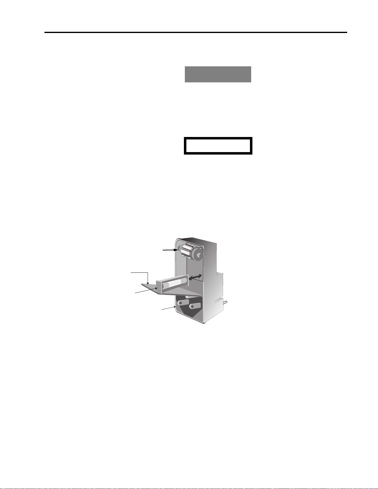
All 2500A Series models have a line fuse holder on the rear panel. The power line fuse is 2A, SlowBlow, 250V, Type T. See Figure 1-1 below for the location of the line fuse.
Not Used
COVER
FUSE AND
FUSE HOLDER
AC POWER
INPUT
Figure 1-1: Fuse Holder
1.2.5.1 Line Fuse Replacement
Open the housing cover. Pull out the small drawer on the right side of the housing (marked with an
arrow) and remove the old fuse. Replace with a new fuse, insert the drawer and close the housing cover,
see Figure 1-1, above.
1
1
0
1
2
0
2500A Series Operation Manual, 34172 Revision C, March 2008

Chapter 1: 2500A Introduction
NOTE: The voltage select wheel shown in Figure 1-1, above, can be set at any position. Its position
has no effect on the 2500A line voltage, as the 2500A line voltage is auto-sensing and autosetting.
1.2.6 Calibration Cycle
Giga-tronics recommends a calibration cycle of two years for the 2500A.
1.2.7 Reshipment Preparation
If it is necessary to return the instrument to the factory, protect it during reshipment using the best packaging materials available. If possible, reuse the original shipping container. If the original shipping container is not available, use a strong carton (350lbs./ sq.in. bursting strength) or a wooden box. Wrap the
instrument in heavy paper or plastic before placing it into the shipping container. Completely fill the
areas on all sides of the instrument with packaging material. Take extra precaution to protect the front
and rear panels. Seal the package with strong tape or metal bands. Mark the outside of the package as follows:
FRAGILE - DELICATE INSTRUMENT
If corresponding with the factory or local Giga-tronics sales office regarding reshipment, please provide
the model and serial number. If the instrument is being returned for repair, be sure to enclose all relevant
information regarding the problem that has been found.
NOTE: If returning an instrument to Giga-tronics for service, first contact Customer Service so that a
return authorization number (RMA) can be assigned. Contact Giga-tronics via email
(repairs@gigatronics.com) or by phone (800.726.4442). The 800 number is only valid within
in the United States. Contact can also occur via our domestic line at (925.328.4640) or Fax at
(925.328.4702).
1.3 Inputs and Outputs
The input and output connectors are shown in figures 1-2 and 1-3. Table 1-3 contains the front and rear
panel I/O connector functional descriptions for all 2500A Series models.
18 2500A Series Operation Manual, 34172 Revision C, March 2008
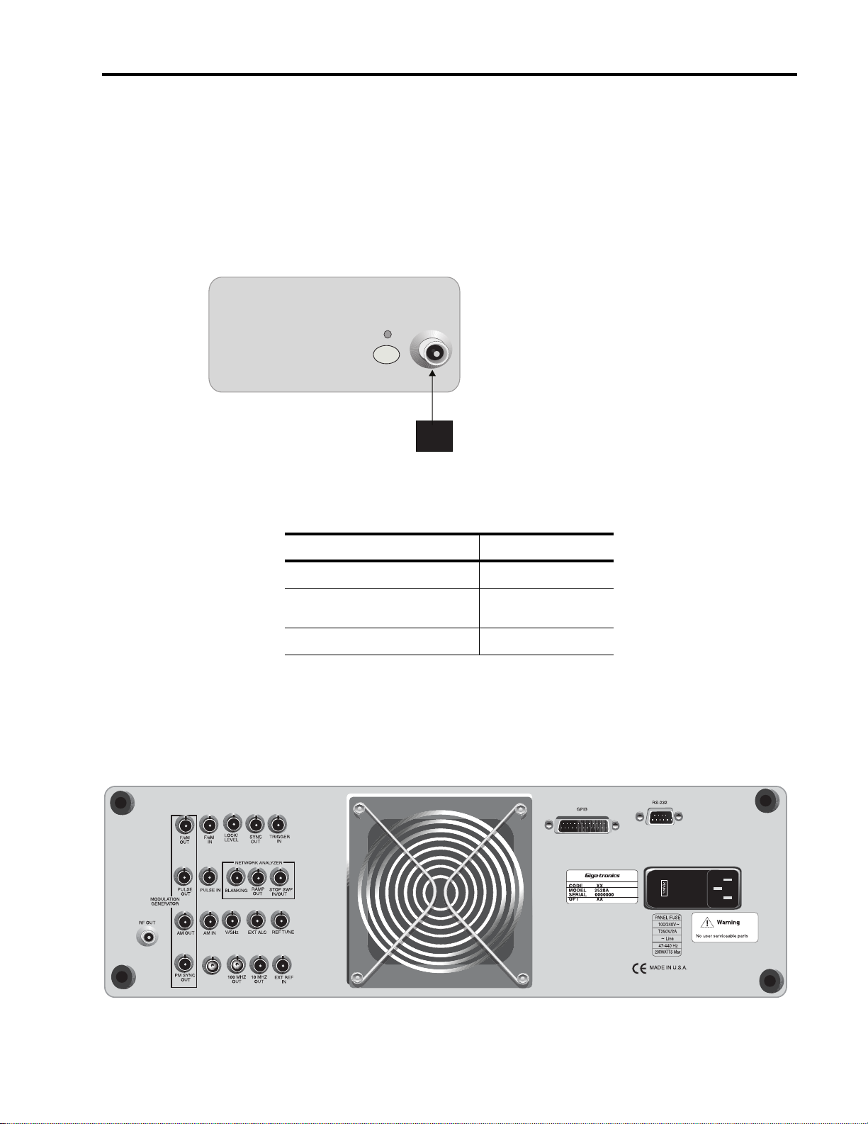
1.3.1 Front Panel Connector (RF Output)
This is the instrument’s RF output. It is located on the front panel of 2500B Series Synthesizer models,
and on the rear panel of versions of 2500S Series models.
The type of RF connector that is supplied depends on the frequency range of the instrument. Figure 1-2
shows the general location of the front panel RF output connector on 2500B Series models, and
Table 1-2 indicates by model the type of RF connector that is supplied.
RF
ON
RF OUT
Figure 1-2: Series 2500B Front Panel Output
ALC IN
Inputs and Outputs
Table 1-2: RF Connector Types
Models RF Connector Type
2508A/2508AS N (f)
2520A/2520AS
2526A/2526AS
2540A/2540AS K (f)
SMA (f)
1.3.2 Rear Panel Interface and I/O Connectors
This section defines the functions of the 2500A Series rear panel connectors (see Figure 1-3).
2500A Series Operation Manual, 34172 Revision C, March 2008

Chapter 1: 2500A Introduction
Figure 1-3: 2500A Rear Panel
All rear panel I/O connectors explained in this section are type BNC unless otherwise stated. Some connectors may not be supported because of installed options. For example, Modulation and Modulation
Generator connectors are not active with Option 17A or 17B. Table 1-3 describes the 2500A rear panel
I/O connectors.
Table 1-3: 2500A Rear Panel I/O Connector Descriptions
Connector Label Description
EXT ALC In external leveling, the output of the 2500B is detected by either a positive or negative
crystal detector or power meter with an analog output. The signals from these devices
are connected to the ALC circuitry of the 2500B which is used to compensate for
standing wave effects or cable and component losses at the input of the device under
test.
See Section 4.2.8 for External ALC specifications
RF OUT The RF signal output for the instrument. See Table 1-2 for RF connector types.
It is located on the front panel for all 2500B Series instruments and rear panel for all
2500S Series instruments.
FM OUT
1
The internal modulation generator output;
2 Vp-p into 10k Ω.
PULSE OUT
AM OUT
1
1
A +4V video representation of the pulsed RF output signal.
The internal modulation generator output;
2 Vp-p into 10k Ω.
PM SYNC OUT
1
A synchronization output pulse of >75 ns width, TTL level that can be delayed relative
to the leading edge of the video signal at the PULSE OUT connector.
2
FM IN
A 50 Ω input for an external FM signal. The input signal can be any waveform
compatible within bandwidth considerations. A 1 Vp input produces maximum
deviation.
An externally supplied DC signal can be applied to modulate the frequency of the CW
output using this connector.
See Section 4.2.6 for DC FM specifications
AM IN
2
A 600 Ω input for an external AM signal. The input signal can be any waveform
compatible within bandwidth considerations. A 1 Vp-p input produces 50% AM depth.
PULSE IN/PM TRIG IN2A Pulse Modulation Input for external pulse gating, pulse triggering or external Pulse In.
The input parameters are +5 volt, 50 Ω
LOCK/LEVEL +5 volt indicator, active high when the 2500A is phase locked and output leveled. The
Lock and Level indicator is valid for CW mode only.
REF TUNE A 0 to +10 volts, high impedance input for tuning the internal reference for adjusting the
output frequency approximately +
5 ppm. Do not exceed +15 volts or apply a negative
voltage greater than -1 volt.
SYNC OUT In List mode, the unit can be set to generate a pulse at this output when a specified list
point is reached. The output can be delayed from the start of the list point up to a
maximum of 10 msec. The pulse width of the SYNC OUT signal is determined by the
following parameters: pulse width = Step Time - Sync Delay - 10 usec
In Ramp operation, the pulse occurs at the start of each ramp sweep.
In either case, the output pulse is +5 volt.
20 2500A Series Operation Manual, 34172 Revision C, March 2008

Inputs and Outputs
Table 1-3: 2500A Rear Panel I/O Connector Descriptions
Connector Label Description
TRIGGER IN Used to trigger a List. Accepts a TTL level signal of > 50 ns width.
BLANKING A +5 volt output signal occurring at band crossings, filter switches, and retraces for the
duration of those events.
RAMP OUT A 0 to 10 volt ramp output scaled to the frequency sweep.
STOP SWP IN/OUT Stop Sweep I/O is a 5 volt, 2 K Ω, active low signal that temporarily interrupts an
instrument frequency or power ramp sweep. This feature is only available with 2500B
models with option 55 and 2500S models with options 55 and 44.
V/GHz An output voltage that is directly proportional to output frequency. For 26 and 40 GHz
models, the output is 0.25 volts per GHz. For 8 and 20 GHz models, the output is 0.5
volts per GHz.
100 MHz OUT A +5 dBm typical, AC coupled, 100 MHz low noise reference output signal into 50 Ω
10 MHz OUT A 2 Vp-p 10 MHz square wave reference output signal into 50 Ω.
EXT REF IN The external reference input. Can be either a 10 MHz input that is >-5.0 dBm into 50 Ω
or a 100 MHz input > +5 dBm. The 100 MHz input level should not exceed +8 dBm for
best performance.
GPIB A 24-pin IEEE STD 488.2 connector for control of the instrument during remote
operation using GPIB.
RS-232 A DB-9 connector for control of the instrument during remote operation using RS-232
serial communications.
AC Power Input 90-253 VAC, auto-sensing, 47 Hz to 440 Hz.
1. Not available with Option 17A or 17B.
2. Not available with Option 17A
.
2500A Series Operation Manual, 34172 Revision C, March 2008

Chapter 1: 2500A Introduction
22 2500A Series Operation Manual, 34172 Revision C, March 2008

Front Panel Operation
2
2.1 Introduction
This chapter describes how to operate the 2500A Series from the front panel.
The information in this chapter pertains primarily to the 2500A Series of Gigatronics Microwave Synthesizers. Note, however, that while the menus, key sequences, etc., presented in this chapter pertain primarily to front panel operation, the features explained are universal for either the front panel or remote
operating modes.
NOTE: Chapter 3 provides instructions on using the 2500A Series from a remote host computer over
the General Purpose Interface Bus (GPIB), an RS-232 serial connection, USB or Ethernet.
2.2 Front Panel At a Glance
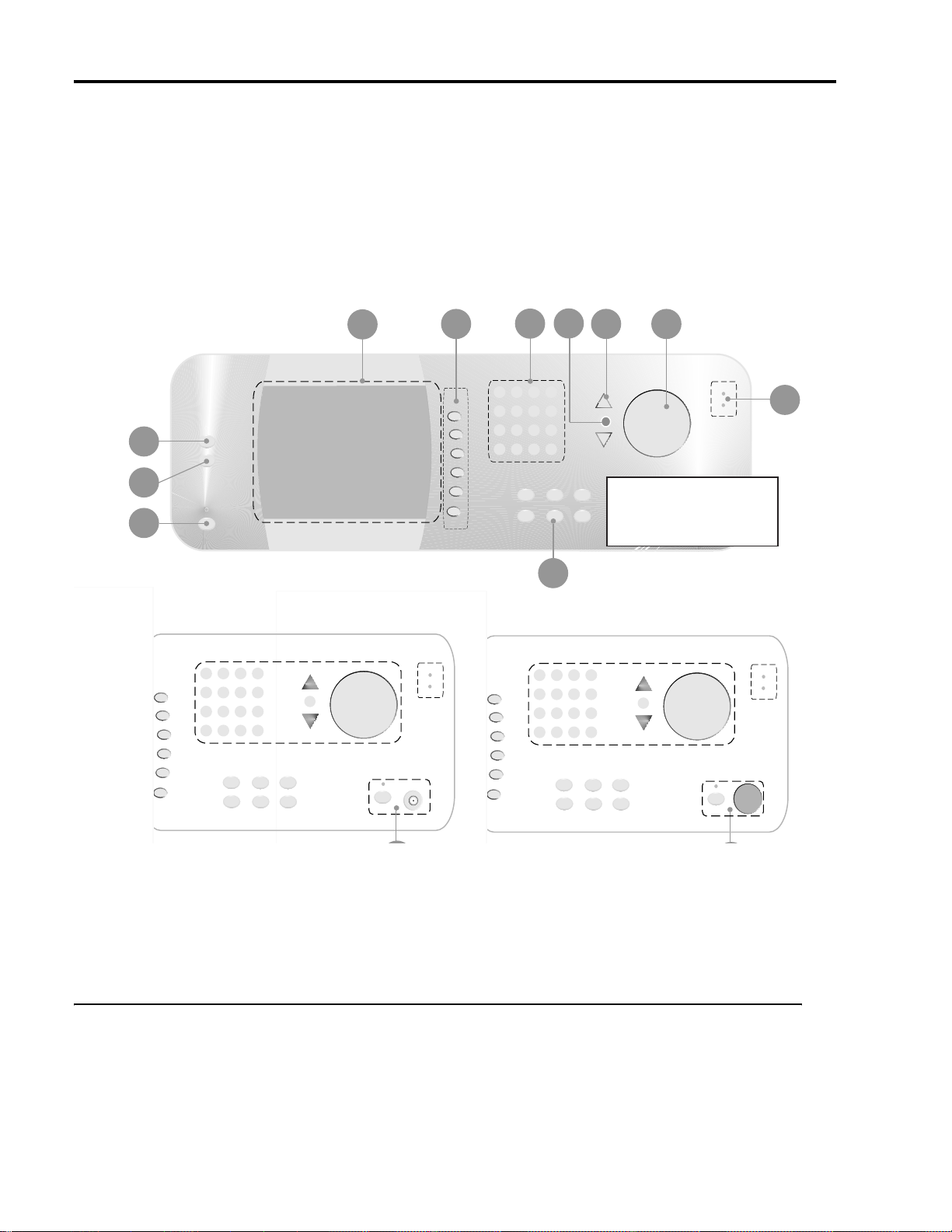
The 2500A Series front panel contains the controls and display for local operation of the instrument.
Some functions are not available from the front panel; they require use of a PC with a compatible remote
interface. Front panel controls are grouped according to the functions they perform. Descriptions for the
front panel controls are referenced to the numbers depicted in Figure 2-1 on the next page.
2500A Series Operation Manual, 34172 Revision C, March 2008
Chapter 2: Front Panel Operation
4
5
6
8
7
9
10
3
2
1
Microwave Synthesizers
Bottom Sectional Differential
See A for 2500A Series
See B for 2500AS S eries
12
Front Panel Layout of 2500 Series Microwave Synthesizers
Figure 2-1: 2500A Front Panel with Callouts
2.2.1 Front Panel Description
Power
The main power switch for the 2500A, which is used to set the power either to on or standby. A blue
indicator indicates that main power button is blue, an amber indicator indicates that the main power is off
but power is applied to the internal timebase oscillator.
24 2500A Series Operation Manual, 34172 Revision C, March 2008

LOCAL Button
1
PRESET Button
Front Panel At a Glance
Allows front panel access when the unit is in remote mode. If the unit is already in local mode, pressing
this button accesses menus that allow you to choose the remote command language to be used by the
instrument while remote operation.
Presets the 2500A to factory defaults, or initializes NVRAM.
2
3
Display
4
Interactive Softkeys
Data Entry Keypad
• Pressing the PRESET button momentarily presets instrument settings to factory default values, but
does not affect system memory locations, display contrast, or the GPIB address.
• Pressing and holding the PRESET button while the unit is powering up initializes NVRAM, which
includes presetting instrument settings to factory default values as well as initializing all ten system
memory locations, the display contrast, and the GPIB address.
Displays current instrument settings, as well as the menus that allow you to modify the settings. The
group of instrument settings and associated menu items that are currently displayed is called the active
display.
Menus are accessed by pressing the menu buttons. The menus appear along the right-hand side of the display adjacent to the interactive softkeys. To select a particular menu item, press the adjacent interactive
softkey. Modify the parameter using the data entry keypad, step-up/step-down buttons, or knob.
Selects the menu items adjacent to them in the display for modification.
A 12-button numeric keypad and adjacent Units buttons for direct entry of instrument parameters.
STEP SIZE Button
5
Selects and allows editing of the step size used by the Step Up/Down buttons and rotary knob. To change
a step size, choose a menu item, press the STEP SIZE button, enter the step size using the keypad, then
press the appropriate units button.
6
Step Up/Down Buttons
Increases or decreases the selected parameter in the display by the amount specified by the step size.
7
Rotary Knob
Increases or decreases the parameter that is selected in the display. When a maximum or minimum limit
is reached, a message will be displayed at the bottom of the display indicating that the parameter limit
has been reached.
8
Front Panel LED indicators
The front panel indicators are located in several places.
2500A Series Operation Manual, 34172 Revision C, March 2008

Chapter 2: Front Panel Operation
9
10
RF Output
Menu Buttons
11
Unleveled Indicator. This indicator is lit when the 2500A output is operating in an unleveled state.
External Reference (Ext Ref) Indicator. This indicator is lit when the 2500A is operating with an
external reference applied.
RF On/Off Indicator. This indicator, which is located above the RF ON button, is blue when the 2500A
RF output is active. When the RF output is inactive, the indicator is not lit.
Power Indicator. This indicator, which is above the main power button, is blue when the unit is on, and
amber when the unit is in standby mode.
This is the RF output section for 2500A Series instruments. The 2500A series connector is located on the
lower left portion of the front panel.
CW Button. Pressing this button displays the CW Menu, which shows parameters related to the CW
functions of the instrument, and the Cable Correction functions and their associated menu items.
RAMP Button. Pressing this button displays either the Ramp Freq or Ramp Power Menu, which shows
parameters related to either the frequency or power ramp (sweep) functions of the instrument, and their
associated menu items.
SYSTEM Button. Pressing this button displays either the System 1 or System 2 Menu, which shows
parameters related to certain system-level functions, and their associated menu items.
12
AM Button. Amplitude modulation is not available on the 2500A.
FM Button. Frequency Modulation is not available on the 2500A.
PM Button. Pressing this button displays the External PM Menu which shows parameters related to the
pulse modulation functions of the instrument, and their associated menu items.
2.3 2500A Menus
This section provides a brief overview of the 2500A’s display and menus, and explains each of the
2500A menus in more detail.
26 2500A Series Operation Manual, 34172 Revision C, March 2008
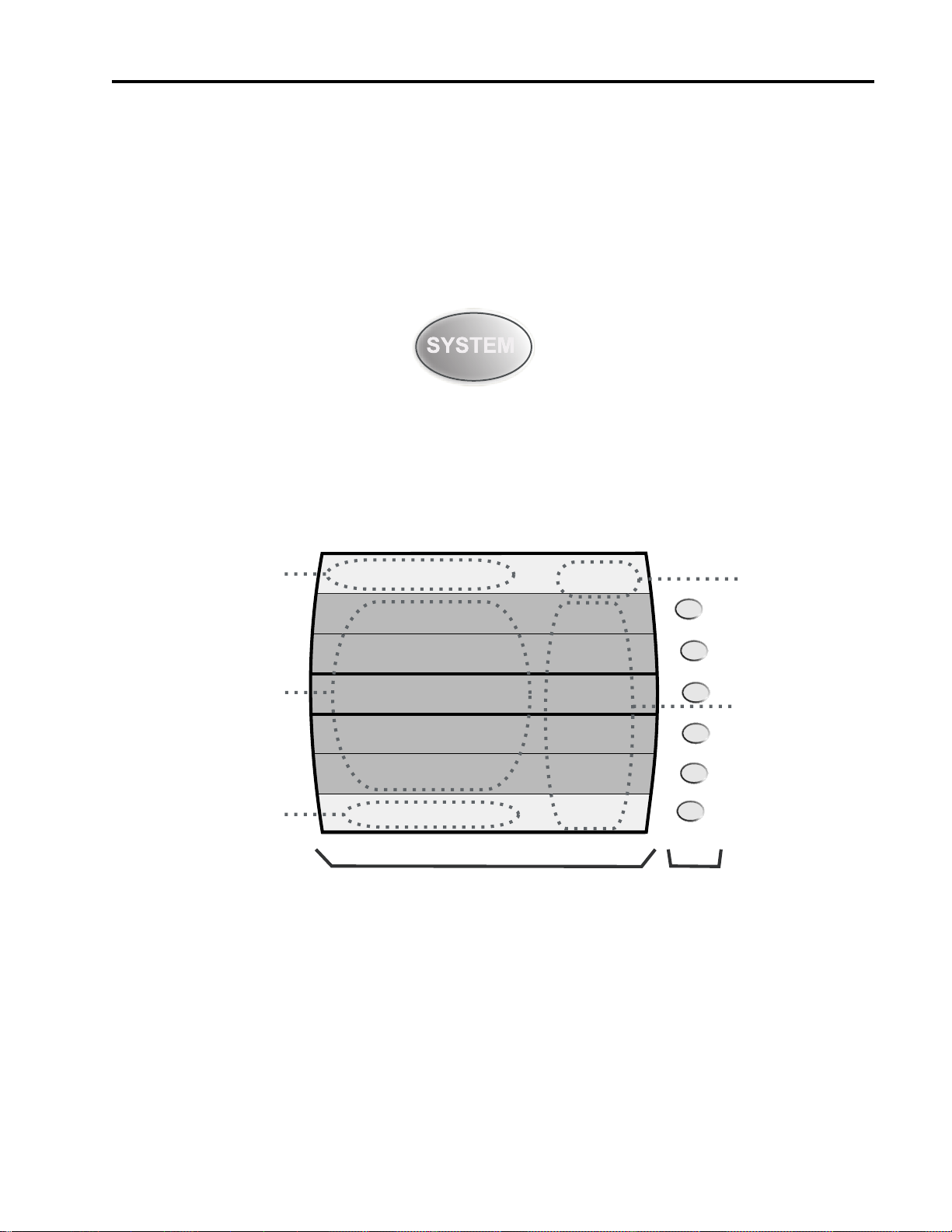
2.3.1 Menu System Overview
SYSTEM 1
OFS SLP
To Register (0-9)
No register has been saved
8
ON
Save
Recall
Sound
Contrast
Auto
Attenuation
System 2
Menu
AM FM PM
Contrast must be <= 15
Menu Area
Mode Indicators
Menu Name
Parameter Area
Error/Step Size Area
Display
Interactive
Softkeys
2.3.1.1 Menu Buttons
Most 2500A features and functions are accessed through a series of menus. The menus are accessed by
pressing one of the menu buttons that are on the front panel of the instrument. As an example, to access
the System menus, press the SYSTEM button:
The following menu buttons are available:
CW, RAMP, SYSTEM, PM, LOCAL.
2500A Menus
The 2500A’s front panel display is divided into several functional areas, as shown in Figure 2-2:
Figure 2-2: Functional Areas of the 2500A Display
The following explains each of the functional areas of the display shown in Figure 2-2:
Menu Name. This is the name of the menu that is currently shown in the front panel display. The menu
that is currently shown is called the active menu.
2500A Series Operation Manual, 34172 Revision C, March 2008
Menu Area. This area displays the various menu choices that are available in the active menu. The row
containing the menu item and parameter that is currently selected is surrounded by bold lines.

Chapter 2: Front Panel Operation
Parameter Area. This area displays the current values of the instrument settings that are associated with
the active menu. Parameters can be modified.
Error/Step Size Area. If applicable, this area shows the currently set step size for the parameter that is
selected for modification. Certain non-error user messages might also be displayed in this area.
Mode Indicators. Indicators will appear in this area of the display if the instrument is currently in any of
several operating modes. If the instrument is currently in a given operating mode, its indicator will
appear regardless of the menu that is currently active. The following indicators are available:
OFS - Appears if a power offset of greater than 0 dB is set in the CW menu.
SLP - Appears if a power slope of greater than 0 dB/GHz is set in the CW menu.
PM - Appears if either internal or external pulse modulation is currently enabled.
EXT. LEVEL - Appears if the ALC is set to External.
UNLK - Appears if the Phase Lock Loop is unlocked.
OVEN COLD - Appears if the internal temperature of the 2500A has not reached operational tem-
perature. It is not recommended to use the 2500A while this indicator is active.
2.3.2 CW Menu Descriptions
The CW menus display the instrument’s currently set CW (continuous wave) frequency, power level,
power offset, and power slope, and allows you to make changes to those settings. The Cable Cal menu
allows you to perform and a apply a cable offset correction to the CW menu power level setting. The
Cable Cal feature requires a Giga-tronics 8650A series power meter or any power meter with a SCPI
compatible command set. To access the CW menu, press the front panel CW menu button:
There are two menus associated with the CW menu button. Figure 2-3 shows the CW menu:
28 2500A Series Operation Manual, 34172 Revision C, March 2008

CW MENU
2500A Menus
6.00 GHz
3.21 dBm
0.00 dB
0.00 dB/GHz
0 Degrees
Step Size: 0.1 Hz
Frequency
Power
Power Offset
Power Slope
Phase
Cable Cal
Menu
Figure 2-3: CW Menu with Interactive Softkeys
The following explains each item in the CW menu:
Frequency. This menu item displays and allows you to modify the instrument’s CW frequency. The
range of the CW frequency parameter is dependent on the model number of the instrument.
Power. This menu item displays and allows you to modify the instrument’s output power level. The
range of the output power level depends on the following configuration and settings of the instrument:
Power Offset. This menu item displays and allows you to modify the instrument’s power offset. The
power offset feature increases the instrument’s output power by the amount of the power offset setting,
without changing the power level as shown in the Display. This allows you to compensate for the insertion or conversion loss of components that are attached to the instrument’s RF output. An example
appears in Figure 2-4.
2400LMicrowave Synthesizer
Power Level Setting = +10 dBm
Power Offset Setting = 2.23 dB
Figure 2-4: Power Offset Example
The Power Offset indicator (OFS) appears in the upper right-hand corner of the display when any power
offset value greater than 0.00 dB is entered.
Power Slope. This menu item displays and allows you to modify the instrument’s power slope. The
power slope feature increases the instrument’s output power linearly as a function of the output frequency. The power slope function allows you to automatically compensate for insertion/conversion
losses of components attached to the instrument’s RF output that exhibit a linear loss characteristic with
2500A Series Operation Manual, 34172 Revision C, March 2008
RF Mixer
×
Conversion Loss = 2.23 dB
+10 dBm is present
at the output of
the RF mixer
Chapter 2: Front Panel Operation
frequency. The Power Slope indicator (SLP) appears in the upper right-hand corner of the display when
any power slope value greater than 0.00 dB/GHz is entered.
Phase Adjust. This menu item displays and allows you to modify the phase of the output signal. The
phase of the signal is maintained until the phase is readjusted or whenever the instrument frequency setting is changed. When the instrument frequency setting is changed, the phase adjust setting is reset to 0
degrees. Phase Adjust is specified for a minimum frequency range of 500 MHz to the maximum frequency range of the instrument. Phase adjust is available for frequencies below 500 MHz however the
output response time of the phase adjust is decreased.
Specifications:
Frequency: 500 MHz to maximum frequency
Range:
Accuracy: <0.2
±360 degrees
°, typical
2.3.2.1 Cable Cal Menu
This menu allows you to generate an offset table for use with the power level setting in the CW menu
using the pre-selected power meter and RS-232 interface. Figure 2-5 shows the Cable Cal RS-232 menu.
A similar menu is displayed if an Agilent EPM power meter is selected.
Cable Cal: RS-232
Cable Cal Cleared
1. Connect NULL modem cable between 2400B & 8650A RS-232 ports
2. Connect BNC cable between 2400B Sync Out and 8650A Trig In
3 Connect calibrated sensor on 8650A Chan A to 2400B RF Out cable
4. Set 8650 RS232 baud rate to 38400 and press Start Cable Cal
Cable Cal sweeps from 10 MHz to 20 GHz.
Cable Cal Setup
Use appropriate sensor
Figure 2-5: Cable Cal RS-232 Menu
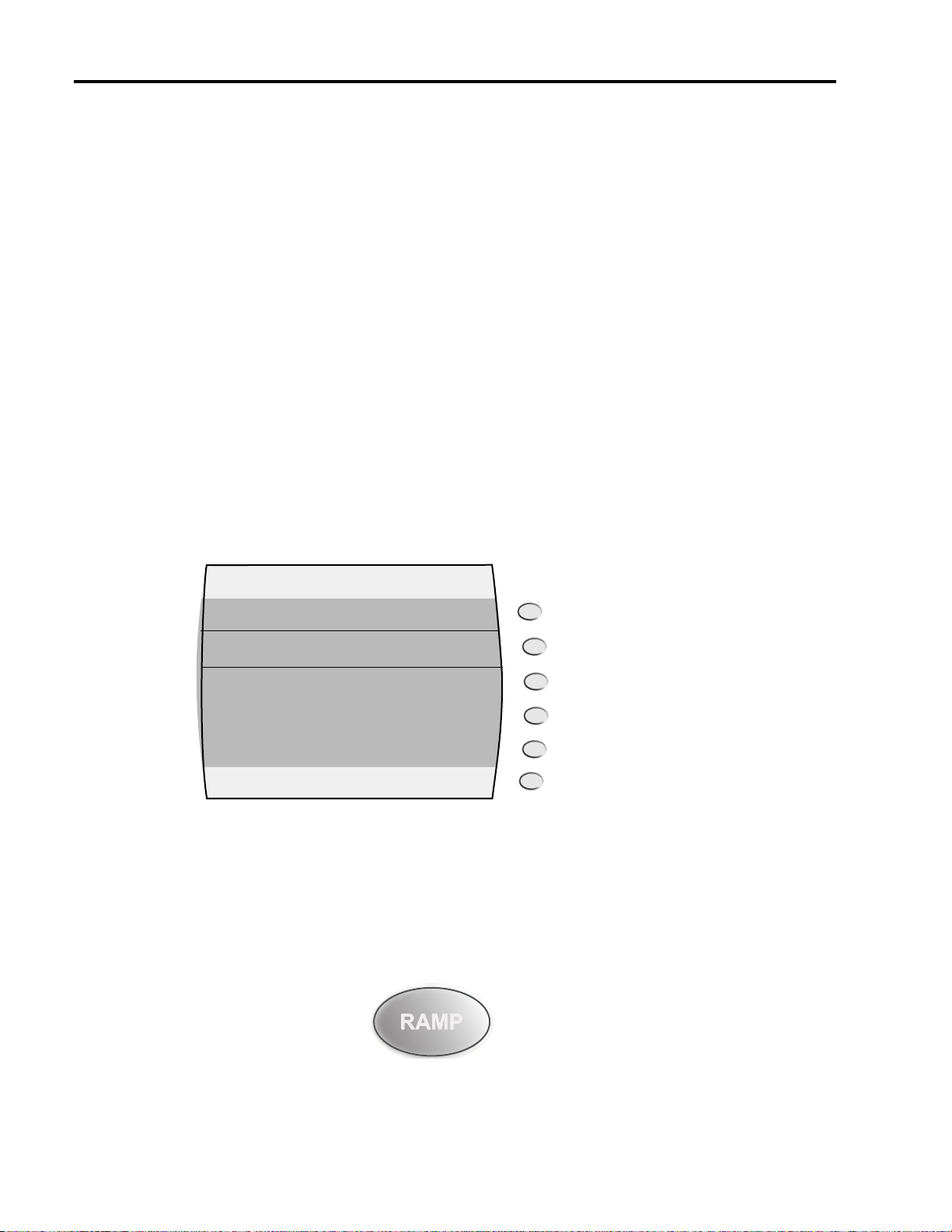
2.3.3 RAMP Menu Descriptions
The RAMP menus display the instrument’s currently set ramp frequency sweep and ramp power sweep
settings, and allow you to make changes to those settings.
Start
Cable Cal
Clear
Cable Cal
CW
Menu
There are 7 menus associated with the RAMP menu button. There is one top level menu that alllows
access to any of the 6 sweep function menus. Figure 2-6 shows the Sweep Main Menu.
30 2500A Series Operation Manual, 34172 Revision C, March 2008

Figure 2-6: Top Level Sweep Menu
Ramp Freq Start/Stop Sweep Menu. Pressing this softkey invokes the Ramp Freq Start/Stop menu in
the display. See “Ramp Freq 1 Menu”, for Ramp Freq menu item descriptions.
Ramp Freq Center/Span Sweep Menu. Pressing this softkey invokes the Ramp Freq Center/Span
menu in the display. See “Ramp Freq 2 Menu”, for Ramp Freq menu item descriptions.
Ramp Power Sweep Menu. Pressing this softkey invokes the Ramp Power Sweep menu in the display.
See “Ramp Power Menu”, for Ramp Power menu item descriptions.
Step Freq Sweep Menu. Pressing this softkey invokes the Step Freq Sweep menu in the display. See
“Step Sweep Freq Menu”, for Step Frequency Sweep menu item descriptions.
2.3.3.1 Ramp Freq 1 Menu
The Ramp Freq 1 menu will generate a frequency sweep where the start and stop frequencies are specified. The Ramp Freq 1 menu allows you to view and modify settings related to the instrument’s frequency sweep features. When this menu is used, the frequency of the RF output can be swept linearly
from a predetermined start frequency to a predetermined stop frequency in a predetermined sweep time.
2500A Menus
NOTE: As soon as any Ramp or Step menu is chosen, the instrument calculates the sweep, then
begins sweeping the output frequency. The ramp is recalculated whenever a parameter is
changed. During calculations, the following message is shown at the bottom of the display:
Preparing sweeping data...
When the calculations are complete and the output is actively sweeping, the following message is shown:
Ramp sweeping
Figure 2-7 shows the Ramp Freq 1menu:
RAMP FREQ 1
10.00 MHz
20.0 GHz
0.00 dBm
1.00 Sec
Start Frequency
Stop Frequency
Power
Sweep Time
401
Ramp sweeping
Resolution
Ramp Freq 2
Menu
2500A Series Operation Manual, 34172 Revision C, March 2008

Chapter 2: Front Panel Operation
Figure 2-7: Ramp Freq Menu with Interactive Softkeys
The following explains each item in the Ramp Freq menu:
Start Frequency. This menu item displays and allows you to modify the ramp start frequency. This is
the frequency that will be used as the starting frequency of the frequency sweep. Note that the start frequency must be less than the stop frequency. If the start frequency is set higher than the stop frequency,
the stop frequency is automatically adjusted to the same value.
Stop Frequency. This menu item displays and allows you to modify the ramp stop frequency. This is the
frequency that will be used as the ending frequency of the frequency sweep. Note that the stop frequency
must be greater than the start frequency. If it is set lower than the start frequency, the start frequency is
automatically adjusted to the same value.
Power. This menu item displays and allows you to modify the output power level to be used during the
frequency sweep. The range of the power level depends on the following configuration and settings of
the instrument:
Sweep Time. This menu item allows you to view and modify the sweep time. This is the amount of time
that elapses for one cycle of a frequency sweep to complete.
Resolution. This menu item allows you to view and modify the sweep step resolution. The sweep step
resolution can be set to 401, 801 and 1601 frequency steps.
Ramp Freq 2 Menu. Pressing this softkey invokes the Ramp Freq 2 menu (Center/Span Frequency)
menu in the display.
2.3.3.2 Ramp Freq 2 Menu
The Ramp Freq 2 Menu will generate a ramp frequency sweep where the center frequency and sweep
span paramters are specified. The menu allows you to view and modify settings related to the instrument’s frequency sweep features. When this menu is used, the frequency of the RF output can be swept
linearly referenced from the center frequency with a predetermined span frequency in a predetermined
sweep time.
Figure 2-8 shows the Ramp Freq Start/Stop menu:
RAMP FREQ 2
10.00 MHz
20.0 GHz
0.00 dBm
Center Freq
Span
Power
1.00 Sec
401
Ramp Sweeping
Sweep Time
Resolution
Ramp Power
Menu
Figure 2-8: Center/Span Ramp Freq Menu with Interactive Softkeys
32 2500A Series Operation Manual, 34172 Revision C, March 2008

2500A Menus
The following explains each item in the Ramp Freq Center/Span menu:
Center Frequency. This menu item displays and allows you to modify the ramp start frequency. This is
the frequency that will be used as the starting frequency of the frequency sweep. Note that the start frequency must be less than the stop frequency. If the start frequency is set higher than the stop frequency,
the stop frequency is automatically adjusted to the same value.
Span Frequency. This menu item displays and allows you to modify the ramp span frequency. The span
determines the range of the frequency weep beginning at half the value of the span setting lower than the
center frequency and ending at a frequency one half the value of the span setting higher than the center
frequency.
Power. This menu item displays and allows you to modify the output power level to be used during the
center/span frequency sweep. The range of the power level can be set to any valid power setting of the
instrument.
Sweep Time. This menu item allows you to view and modify the sweep time. This is the amount of time
that elapses for one cycle of a frequency sweep to complete.
Resolution. This menu item allows you to view and modify the sweep step resolution. The sweep step
resolution can be set to 401, 801 and 1601 frequency steps.
Ramp Power Menu. Pressing this softkey invokes the Ramp Power menu in the display. See “Ramp
Power Menu”, below, for Ramp Power menu item descriptions.
2.3.3.3 Ramp Power Menu
The Ramp Power menu allows you to view and modify settings related to the instrument’s power sweeping feature. When this feature is used, the power level of the RF output sweeps linearly from a predetermined start power level to a predetermined stop power level in a predetermined amount of time, then
repeats. The power level can sweep from a lower to a higher power level, or vice versa. The output frequency is held at the same value during a power sweep. The maximum settable range for ramp power
sweep is 45 dB.
NOTE: As soon as the Ramp Power menu is chosen, the instrument calculates the ramp, then begins
sweeping the output power. The ramp is recalculated whenever a parameter is changed. During calculations, the following message is shown at the bottom of the display:
Preparing sweeping data...
When the calculations are complete and the output is actively sweeping, the following message is shown:
Ramp sweeping
Figure 2-9 shows the Ramp Power menu:
2500A Series Operation Manual, 34172 Revision C, March 2008

Chapter 2: Front Panel Operation
RAMP POWER
0.00 dBm
10.00 dBm
10.00 GHz
25.00 Sec
0
Ramp Sweeping
Start Power
Stop Power
Frequency
Sweep Time
Attenuation
Step Sweep
Menu
Figure 2-9: Ramp Power Menu with Interactive Softkeys
The following explains each item in the Ramp Power menu:
Start Power. This menu item displays and allows you to modify the ramp start power level. This is the
power level that will be used as the beginning of the power level sweep.
The range for the start power parameter is -20 dBm to +25 dBm if the 90 dB step attenuator is not
installed in the instrument. If the 90 dB step attenuator is installed, the start power range is from 25 dB
above to 20 dB below the step attenuator setting chosen.
Stop Power. This menu item displays and allows you to modify the ramp stop power level. This is the
power level that will be used as the end point of the power level sweep.
The range for the stop power parameter is -20 dBm to +25 dBm if the 90 dB step attenuator is not
installed in the instrument. If the 90 dB step attenuator is installed, the stop power range is from 25 dB
above to 20 dB below the step attenuator setting chosen.
Frequency. This menu item displays and allows you to modify the output frequency to be used during
the power level sweep. The range of the frequency parameter is dependent on the model number of the
instrument.
Sweep Time. This menu item allows you to view and modify the sweep time. This is the amount of time
that elapses for one cycle of a power level sweep to complete.
Attenuation. This menu item allows you to select a range of the step attenuator if it is installed in the
instrument. The step attenuator can insert up to 90 dB of attenuation into the RF output path of the instrument, in selectable 10 dB steps.
Step Sweep Menu. Pressing this softkey invokes the Ramp Freq menu in the display. See “Ramp Freq 1
Menu”, above, for Ramp Freq menu item descriptions.
2.3.3.4 Step Sweep Freq Menu
The Step Sweep menu allows you to view and modify settings related to the instrument’s frequency
sweeping feature. When this feature is used, the frequency of the RF output sweeps linearly from a predetermined start frequency to a predetermined stop frequency in a predetermined sweep time, then
34 2500A Series Operation Manual, 34172 Revision C, March 2008

2500A Menus
repeats. The sweep occurs in a set number of equal increments, as determined by the Resolution setting.
The output power is held at the same level during a frequency sweep.
NOTE: As soon as theStep Swep menu is chosen, the instrument calculates the ramp, then begins
sweeping the output frequency. The ramp is recalculated whenever a parameter is changed.
During calculations, the following message is shown at the bottom of the display:
Preparing sweeping data...
When the calculations are complete and the output is actively sweeping, the following message is shown:
Step sweeping
Figure 2-10 shows the Step Sweep menu:
RAMP FREQ
10.00 MHz
20.0 GHz
0.00 dBm
1.00 Sec
401
Start Frequency
Stop Frequency
Power
Sweep Time
Resolution
Ramp Power
Menu
Figure 2-10: Ramp Freq Menu with Interactive Softkeys
The following explains each item in the Ramp Freq menu:
Start Frequency. This menu item displays and allows you to modify the ramp start frequency. This is
the frequency that will be used as the starting frequency of the frequency sweep. Note that the start frequency must be less than the stop frequency. If the start frequency is set higher than the stop frequency,
the stop frequency is automatically adjusted to the same value.
Stop Frequency. This menu item displays and allows you to modify the ramp stop frequency. This is the
frequency that will be used as the ending frequency of the frequency sweep. Note that the stop frequency
must be greater than the start frequency. If it is set lower than the start frequency, the start frequency is
automatically adjusted to the same value.
Power. This menu item displays and allows you to modify the output power level to be used during the
frequency sweep. The range of the power level depends on the following configuration and settings of
the instrument:
Step Ti me. This menu item allows you to view and modify the step time. This is the amount of time that
a single frequency step is executed. When the last frequency in the step sweep is executed and com-
2500A Series Operation Manual, 34172 Revision C, March 2008

Chapter 2: Front Panel Operation
pleted, the sweep continues with the start frequency and cycles continuously until a change in the menu
made or
Step Size. This menu item allows you to view and modify the frequency step size. The step size can be
set to the minimum frequency resolution of the synthesizer to the maximum frequency range of the synthesizer.
Ramp Freq 1 Menu. Pressing this softkey invokes the Ramp Freq 1 menu in the display. See “Ramp
Freq 1 Menu”, below, for Ramp Power menu item descriptions.
2.3.4 SYSTEM Menu Descriptions
The System menus provide access to system-level settings, such as memory storage locations, GPIB
address configuration, display contrast, and system volume control. System information, including the
model number, serial number, firmware version, etc., can also be displayed. To access the
System menus, press the front panel SYSTEM menu button:
There are three menus associated with the SYSTEM menu button.
2.3.4.1 System 1 Menu
The System 1 menu allows you to save instrument states to non-volatile memory and subsequently recall
them, and view and set the display contrast, turn system sound (audio feedback) on or off, and view and
configure the step attenuator if the 90 dB step attenuator is installed.
Figure 2-11 shows the System 1 menu:
SYSTEM 1
To Register (0-9)
No register has been saved
8
ON
Auto
Figure 2-11: System 1 Menu with Interactive Softkeys
Save
Recall
Contrast
Sound
Attenuation
System 2
Menu
The following explains each item in the System 1 menu:
36 2500A Series Operation Manual, 34172 Revision C, March 2008

2500A Menus
Save. This menu item allows you to save the current state of the instrument to non-volatile memory, so
that the saved state can subsequently be restored. The 2500A contains ten registers, numbered 0 through
9, into which instrument states can be saved. Note that saving an instrument state to a given register overwrites any state that might have previously been stored in that register.
To save the current instrument configuration to a given register, select the Save menu item, enter the
number of the register into which you wish to save the configuration using the numeric keypad, then
press any units button.
Only the numeric keypad can be used to enter a register number; the step up/step down buttons and
rotary knob cannot be used.
Recall. This menu item allows you to recall a previously saved instrument state from any of the ten storage registers contained in the instrument’s non-volatile memory.
The parameter area in the display shows the following text:
From Register (X)
Where X is the list of registers, separated by commas, that currently have an instrument state saved in
them. For example, if instrument states are currently stored in registers 1, 2, and 5, the parameter area
would read as follows:
From Register (1, 2, 5)
If none of the registers have instrument states saved to them, as would be the case after the instrument’s
memory is cleared, the following is displayed in the parameter area:
No register has been saved
To recall a previously saved instrument configuration, press the Recall softkey, enter the number of the
register from which you wish to recall the configuration using the numeric keypad, then press any units
button.
Only the numeric keypad can be used to enter a register number; the step up/step down buttons and
rotary knob cannot be used.
Contrast. This menu item allows you to set the contrast of the instrument’s front panel display. The contrast range is 1 to 15, where 1 represents most contrast and results in the darkest display, and 15 represents least contrast and results in the lightest display.
Sound. This menu item allows you to enable or disable (mute) the system sound.
The available selections are ON and MUTE. When Sound is set to ON, the instrument provides audio
feedback whenever a button is pressed or the knob is rotated, and an operational error notification is
emitted when an error condition occurs, such as when an improper button sequence is pressed, a parameter limit is exceeded, etc.
Attenuation. This menu item provides control of the step attenuator if it is installed in the instrument.
2500A Series Operation Manual, 34172 Revision C, March 2008

Chapter 2: Front Panel Operation
The step attenuator can insert up to 90 dB of attenuation into the RF output path of the instrument. It is
switchable in 10 dB steps, and can be set to automatically switch as the instrument’s power level is varied, or it can be manually set to insert a fixed amount of attenuation.
System 2 Menu. Pressing this softkey invokes the System 2 Menu in the display. See “System 2 Menu”,
below, for System 2 Menu item descriptions.
2.3.4.2 System 2 Menu
The System 2 menu allows you to view and modify the instrument’s GPIB address, ALC setting, and
view system information.
Figure 2-12 shows the System 2 menu:
SYSTEM 2
6
Internal
General Information
Model: GT2520A
Version: XXXX
Serial Number: XXXX
Build Date/Time: Dec 1 2006, 18:40:31
GPIB Address
ALC
System 3
Menu
Figure 2-12: System 2 Menu with Interactive Softkeys
The following explains each item in the System 2 menu:
GPIB Address. This menu item allows you to set the instrument’s General-Purpose Interface Bus
(GPIB) address. The GPIB address range is 1 to 30.
ALC. This menu item allows you to set the instrument's ALC input. The ALC input settings are Internal,
Positive Detector, Negative Detector and Power Meter. External ALC enables the instrument to compensate for device transmission losses without user intervention.
General Information. This field displays 2500A system information. This information is for display
only; it has no associated menu choice. The following information is displayed:
• Model - This is the specific model number of the instrument.
• Version - This is the specific firmware version installed in the instrument.
• Serial Number - This is the instrument’s serial number.
• Build Date/Time - This is the date and time when the firmware version was created.
System 3 Menu Pressing this softkey invokes the System 3 Menu in the display.
38 2500A Series Operation Manual, 34172 Revision C, March 2008

2.3.4.3 System Menu 3
The System 3 menu allows you to tune the output frequency over a range of 500 ppm using the REF
TUNE feature.
Figure 2-13 shows the System 3 menu.
SYSTEM 3
Disabled
External Tune
Input
System 4
Menu
2500A Menus
Figure 2-13: System 3 menu with Interactive Softkeys.
External Tune Input. This menu item allows you to enable or disable the instrument’s Reference Tune
feature.
System 4 Menu Pressing this softkey invokes the System 4 Menu in the display.
2.3.4.4 System Menu 4
The System Menu 4 allows you to set up the 2500A for remote operations using the LAN connection.
Figure 2-14 shows the System 4 menu.
SYSTEM 4
On/Off
123.456.789.012
123.456.789.012
Connection Established/Lost
DHCP
IP Address
Subnet Mask
Link Status
System 1
Menu
Figure 2-14: System 4 menu with interactive Sofkeys
2500A Series Operation Manual, 34172 Revision C, March 2008

Chapter 2: Front Panel Operation
DHCP. This menu item allows you to configure the 2500A Dynamic Host Configuration Protocol to be
set manually or allow a DHCP server to obtain the IP and Subnet Mask. When the DHCP is set to Off,
the previously stored static IP address will be displayed.
IP Address. This menu item allows you to set the instrument’s IP (Internet Protocol) address. The range
for each of the sections is 0 to 255.
Subnet Mask. This menu item allows you to set the instrument’s Subnet Mask. The range for each of the
sections is 0 to 255.
Connection Established/Lost. This menu item serves as a link status indicating whether the 2500A ethernet connection is established or disconnected.
The default port number for the 2500A series is 2550
2.3.5 AM Menu Descriptions
The AM menus provide access to the internal and external amplitude modulation features of the instrument. To access the main AM menus, press the front panel AM menu button:
There are three menus that can be accessed from the main AM Menu.
Figure 2-15 shows the main AM menu.
Figure 2-15: AM Main Menu with Interactive Soft Keys
AM Ext Menu. Pressing this softkey invokes the externally driven Amplitude Modulation menu in the
display. See “External AM Menu”, for AM Ext menu item descriptions.
AM Int Menu. Pressing this softkey invokes the internally driven Amplitude Modulation menu in the
display. See “AM - Internal Waveform”, for AM Int menu item descriptions.
AM Int Noise Menu. Pressing this softkey invokes the Amplitude Modulation Internal Noise menu in
the display. See “AM - Internal Noise”, for AM Ext menu item descriptions.
2.3.5.1 External AM Menu
The AM - External Menu allows you to view and modify settings related to external amplitude modulation mode, which is used when the modulating signal is to be provided externally. In external AM mode,
the RF output signal is modulated according to the signal that is applied to the rear panel
AM IN connector.
Figure 2-16 shows the AM External Menu:
40 2500A Series Operation Manual, 34172 Revision C, March 2008

AM - External
2500A Menus
On/Off
0.00% / V
AM
Sensitivity
Figure 2-16: AM - External menu with Interactive Softkeys
The following explains each item in the AM - External menu:
AM. This menu item turns amplitude modulation on and off. Note that this setting only enables or disables amplitude modulation; it is the active menu, that is, the menu that is currently being displayed, that
determines the AM mode that is used. Pressing either the adjacent soft key or the Step Up or Step Down
buttons toggle the AM state.
The AM indicator is displayed in the upper right-hand corner of the display when amplitude modulation
is turned on.
Sensitivity. This menu item allows you to view and modify the AM sensitivity setting. AM sensitivity
determines the percentage of modulation produced per volt of input into the AM IN connector.
The AM sensitivity can be modified using either the numeric keypad, the step up/step down buttons, or
the rotary knob. The AM sensitivity range is 0 to 95%/volt, and the step size can be set in the range of
0.10 to 47.5%/volt.
2.3.5.2 AM - Internal Waveform
The AM - Internal Waveform menu allows you to view and modify settings related to an internal amplitude modulation mode in which the modulating signal is an internally-generated sine, triangle, ramp, or
square waveform (the signal at the AM IN connector is not used).
Figure 2-17 shows the AM - Internal Waveform menu:
2500A Series Operation Manual, 34172 Revision C, March 2008

Chapter 2: Front Panel Operation
AM - Internal Waveform
On/Off
30.00%
1.00 KHz
Ramp
AM
Depth
Rate
Waveform
Figure 2-17: AM - Internal Waveform with Interactive Softkeys
The following explains each item in the AM- Internal Waveform menu:
AM. TThis menu item turns amplitude modulation on and off. Note that this setting only enables or disables amplitude modulation; it is the active menu, that is, the menu that is currently being displayed, that
determines the AM mode that is used. Pressing either the adjacent soft key or the Step Up or Step Down
buttons toggle the AM state.
Depth. This menu item allows you to view and modify the AM depth setting, which is the extent of the
variation of the modulated RF output signal’s amplitude expressed as a percentage.
Rate. This menu item allows you to view and modify the rate (frequency) of the internal modulating signal.
Wav eform. This menu item allows you to view and choose the type of waveform used as the internal
modulating signal. The available selections are Sine, Triangle (symmetrical triangle wave), Ramp (positive going ramp), or Square (50% duty cycle square wave).
2.3.5.3 AM - Internal Noise
The AM - Internal Noise menu allows you to view and modify settings related to an internal amplitude
modulation mode in which the modulating signal is an internally-generated Gaussian noise source (the
signal at the AM IN connector is not used).
Figure 2-18 shows the AM - Internal Noise menu:
42 2500A Series Operation Manual, 34172 Revision C, March 2008

AM - Internal Noise
2500A Menus
On/Off
0.00% / V
AM
Depth
Figure 2-18: AM - Internal Noise with Interactive Softkeys
The following explains each item in the AM - Internal Noise menu:
AM. This menu item turns amplitude modulation on and off. Note that this setting only enables or disables amplitude modulation; it is the active menu, that is, the menu that is currently being displayed, that
determines the AM mode that is used. Pressing either the adjacent soft key or the Step Up or Step Down
buttons toggle the AM state.
Depth. This menu item allows you to view and modify the AM depth setting, which is the extent of the
variation of the modulated RF output signal’s amplitude expressed as a percentage.
AM Main Menu
2.3.6 FM Menu Descriptions
The FM menus provide access to the internal and external frequency modulation features of the instrument. To access the FM Main menu, press the front panel FM menu button:
AM Ext Menu
AM Int Menu
AM Int Noise Menu
2500A Series Operation Manual, 34172 Revision C, March 2008

Chapter 2: Front Panel Operation
There are three FM that can be accessed.
2.3.6.1 FM - External Menu
The FM -External menu allows you to view and modify settings related to external frequency modulation
mode, which is used when the modulating signal is to be provided externally. In external FM mode, the
RF output signal is modulated according to the signal that is applied to the rear panel
FM/
φM IN connector.
Figure 2-19 shows the FM - External menu:
FM - External
On/Off
0.00 Hz / Volt
FM
Sensitivity
Figure 2-19: FM - External Menu with Interactive Softkeys
The following explains each item in the FM - External menu:
FM. This menu item turns frequency modulation on and off. Note that this setting only enables or disables amplitude modulation; it is the active menu, that is, the menu that is currently being displayed, that
determines the FM mode that is used. Pressing either the adjacent soft key or the Step Up or Step Down
buttons toggle the FM state.
Sensitivity. This menu item allows you to view and modify the external FM sensitivity setting, which
determines how much the RF output deviates in frequency per volt of signal at the rear panel FM/
φM IN
connector.
2.3.6.2 FM - Internal Menu
The FM - Internal menu allows you to view and modify settings related to an internal frequency modulation mode in which the modulating signal is an internally-generated sine, triangle, ramp, or square waveform (the signal at the FM/φM IN connector is not used).
Figure 2-20 shows the FM - Internal menu:
44 2500A Series Operation Manual, 34172 Revision C, March 2008

FM - Internal
2500A Menus
On/Off
0.00 Hz
10.00 kHz
Sine
FM
Deviation
Rate
Waveform
Figure 2-20: FM - Internal with Interactive Softkeys
The following explains each item in the FM - Internal menu:
FM. This menu item turns FM - Internal on and off. FM - Internal is an internally driven modulation
requiring a + 1 V peak to peak input for maximum deviation. FM - Internal can only be activated or deactivated using the step up/step down buttons.
Deviation. This menu item allows you to view and modify the FM deviation setting, which determines
how much the RF output deviates in frequency when modulated by the internal source.
Rate. This menu item allows you to view and modify the rate (frequency) of the internal modulating signal.
Wav eform. This menu item allows you to view and choose the type of waveform used as the internal
modulating signal. The available selections are Sine, Triangle (symmetrical triangle wave), Ramp (positive going ramp), or Square (50% duty cycle square wave).
2.3.6.3 DC FM Menu
The FM Menu 3 menu allows you to activate and deactivate the DC FM feature of the instrument. DC
FM requires an externally provided signal to modulate the output frequency of the instrument. In DC FM
mode, the RF output signal is modulated according to the signal that is applied to the rear panel
FM/
φM IN connector. DC FM is available on all models including models with option 17A, Delete Mod-
ulation Suite. Frequency range for DC FM operation is 500 MHz to the maximum frequency of the
instrument with a fixed maximum deviation of 125 kHz. DC FM operation is available for frequencies
below 500 MHz however maximum deviation is limited to the frequency band maximum deviation of
the output frequency.
Figure 2-21 shows the FM Menu 2 menu:
2500A Series Operation Manual, 34172 Revision C, March 2008

Chapter 2: Front Panel Operation
DC FM
On/Off
Figure 2-21: DC FM with Interactive Softkey
The following explains each item in the DC FM menu:
DC FM. This menu item turns frequency modulation on and off. Note that this setting only enables or
disables amplitude modulation; it is the active menu, that is, the menu that is currently being displayed,
that determines the FM mode that is used. Pressing either the adjacent soft key or the Step Up or Step
Down buttons toggle the FM state.
2.3.7 PM Menu Descriptions
DC FM
The PM menus provide access to the internal and external pulse modulation features of the instrument.
To access the PM Main menu, press the front panel PM menu button:
There are five menus associated with the PM menu button.
Figure 2-22 shows the PM Main menu
Figure 2-22: PM Main Menu with Interactive Soft Keys
PM Ext Menu. Pressing this softkey invokes the externally driven Pulse Modulation menu in the dis-
play. See “PM - External Source Menu”, for PM Ext menu item descriptions.
PM Int Cont Menu. Pressing this softkey invokes the internally driven Pulse Modulation menu in the
display. See “PM Internal-Continuous Menu”, for PM Int menu item descriptions.
PM Int Gated Menu. Pressing this softkey invokes the gated, internally driven Pulse Modulation menu
in the display. See “PM Internal-Gated Menu”, for PM Int Gated menu item descriptions.
PM Int Trig Menu. Pressing this softkey invokes the externally driven Amplitude Modulation menu in
the display. See “PM Internal-Triggered Menu”, for PM Ext menu item descriptions.
46 2500A Series Operation Manual, 34172 Revision C, March 2008

2.3.7.1 PM - External Source Menu
The PM - External menu allows you to view and modify settings related to external pulse modulation
mode, which is used when the modulating signal is to be provided externally. In external PM mode, the
RF output signal is pulsed according to the signal that is applied to the rear panel PULSE IN/PM TRIG
IN connector. When the instrument does not include the internal modulation generator, this is the only
PM mode that is available.
Figure 2-23 shows the PM Menu 1 menu:
PM - External Source
2500A Menus
On/Off
Active High/Active Low
PM
Input
Polarity
Figure 2-23: PM Menu 1 with Interactive Softkeys
The following explains each item in the PM Menu 1 menu:
PM. TThis menu item turns pulse modulation on and off. Pressing either the adjacent soft key or the Step
Up or Step Down buttons toggle the PM state. The PM indicator is displayed in the upper right-hand corner of the display when pulse modulation is turned on
Input Polarity. This menu item allows you to view and choose the input polarity. Input polarity determines whether a high or low TTL level at the PULSE IN/PM TRIG IN connector will produce an “on”
condition at the RF output. The available selections are as follows:
• Active High
• Active Low
2.3.7.2 PM Internal-Continuous Menu
The PM - Internal Continuous menu allows you to view and modify settings related to an internal pulse
modulation mode which produces a continuous pulse modulated RF output with pulse characteristics
determined by an internally-generated pulse signal (any signal at the PULSE IN/PM TRIG IN connector
is ignored).
NOTE: This menu is not available for models with Option 17B.
2500A Series Operation Manual, 34172 Revision C, March 2008

Chapter 2: Front Panel Operation
Figure 2-24 shows the PM Menu 2 menu:
PM Internal-Continuous
On/Off
0.1 µs-1sec PRI
0.05 µs-0.01sec
0-(width-50ns)
PM
Width
Sync out
Delay
Figure 2-24: PM Menu 2 with Interactive Softkeys
The following explains each item in the PM Menu 2 menu:
PM. This menu item turns pulse modulation on and off. Pressing either the adjacent soft key or the Step
Up or Step Down buttons toggle the PM state. The PM indicator is displayed in the upper right-hand corner of the display when pulse modulation is turned on
PRI. This menu item allows you to view and modify the PRI (pulse repetition interval) of the internal
pulse modulating signal. The PRI parameter sets the time between like edges of the modulating signal,
and thus, the RF output’s pulse repetition interval (frequency).
NOTE: The same PRI parameter setting gets used for the internal continuous and internal gated pulse
modulation modes; it is not set and stored separately for those modes.
Width. This menu item allows you to view and modify the width of the internal pulse modulating signal.
The width parameter sets the amount of time that each pulse of the internal modulating signal is at the
high state, and thus, the RF output’s pulse width.
NOTE: The same width parameter setting gets used for all three internal pulse modulation modes
(continuous, triggered, and gated); it is not set and stored separately for each of those modes.
Sync Out Delay. This menu item allows you to view and modify the sync out delay setting, which determines the amount of delay that occurs between the leading edge of the video pulse at the PULSE OUT
connector and the leading edge of the sync pulse at the PM SYNC OUT connector.
48 2500A Series Operation Manual, 34172 Revision C, March 2008

NOTE: The same sync out delay parameter setting gets used for all three internal pulse modulation
modes (continuous, triggered, and gated); it is not set and stored separately for each of those
modes.
2.3.7.3 PM Internal-Gated Menu
The PM Internal-Gated menu allows you to view and modify settings related to the internal gated pulse
modulation mode. In this mode, the instrument’s CW signal is pulse modulated according to the PRI and
Width settings of its internal pulse modulation generator, but appears at the RF output connector as determined by the gating signal that is applied to the rear-panel PULSE IN/PM TRIG IN connector.
Figure 2-25 shows the PM Menu 3 menu:
PM Internal-Gated
2500A Menus
On/Off
0.1 µs-1sec PRI
0.05 µs-0.01sec
0-(width-50ns)
Active High/Active Low
PM
Width
Sync out
Delay
Trigger
In
Figure 2-25: PM Internal Gated 3 with Interactive Softkeys
NOTE: This menu is not available for models with Option 17B.
The following explains each item in the PM Menu 3 menu:
PM. This menu item turns pulse modulation on and off. Pressing either the adjacent soft key or the Step
Up or Step Down buttons toggle the PM state. The PM indicator is displayed in the upper right-hand corner of the display when pulse modulation is turned on
PRI. This menu item allows you to view and modify the PRI (pulse repetition interval) of the instrument’s internal pulse modulating signal. The PRI parameter sets the time between like edges of the modulating signal, and thus, the pulse repetition interval (frequency) of the pulses that appear at the RF
output connector when an appropriate gating signal is applied to the rear-panel PULSE IN/PM TRIG IN
connector.
2500A Series Operation Manual, 34172 Revision C, March 2008

Chapter 2: Front Panel Operation
NOTE: The same PRI parameter setting gets used for the internal continuous and internal gated pulse
modulation modes; it is not set and stored separately for those modes.
Width. This menu item allows you to view and modify the width of the internal pulse modulating signal.
The width parameter sets the amount of time that each pulse of the internal modulating signal is at the
high state, and thus, the width of the pulses that appear at the RF output connector when an appropriate
gating signal is applied to the rear-panel PULSE IN/PM TRIG IN connector.
If the width parameter is set to a value that is more than the current PRI setting, the PRI setting is automatically adjusted to be 120 ns greater than the Width setting. The step size can be set in the range of 10
ns to 5 ms.
NOTE: The same width parameter setting gets used for all three internal pulse modulation modes
(continuous, triggered, and gated); it is not set and stored separately for each of those modes.
Sync Out Delay. This menu item allows you to view and modify the sync out delay setting, which determines the amount of delay that occurs between the leading edge of the pulse video and the leading edge
of the sync pulse at the PM SYNC OUT connector.
NOTE: The same sync out delay parameter setting gets used for all three internal pulse modulation
modes (continuous, triggered, and gated); it is not set and stored separately for each of those
modes.
Trigger In. This menu item allows you to view and choose the active polarity of the externally applied
gating signal. This setting determines whether a high or low TTL level at the PULSE IN/PM TRIG IN
connector will be the active gating condition for a pulse modulated RF output. The available selections
are as follows:
• Active High
• Active Low
2.3.7.4 PM Internal-Triggered Menu
The PM Internal-Triggered menu allows you to view and modify settings related to the internal triggered
pulse modulation mode. In this mode, the instrument produces a single RF pulse at the RF output connector whenever it receives a valid trigger signal at the rear-panel PULSE IN/PM TRIG IN connector.
The RF pulse thus generated has a width that is determined by the Width setting in this menu, and is
delayed by the amount of delay set with the RF Pulse Delay setting in this menu.
Figure 2-26 shows the PM Menu 4 menu:
50 2500A Series Operation Manual, 34172 Revision C, March 2008

PM Internal-Triggered
2500A Menus
On/Off
0.1 µs-1sec
0.05 µs-0.01sec
0-(width-50ns)
Rising Edge/Falling Edge
PM
RF Pulse
Delay
Width
Sync out
Delay
Trigger
Polarity
Figure 2-26: PM Menu 4 with Interactive Softkeys
The following explains each item in the PM Menu 4 menu:
PM. TThis menu item turns pulse modulation on and off. Pressing either the adjacent soft key or the Step
Up or Step Down buttons toggle the PM state. The PM indicator is displayed in the upper right-hand corner of the display when pulse modulation is turned on
RF Pulse Delay. This menu item allows you to view and modify the RF pulse delay setting, which determines the amount of delay that occurs between the chosen triggering edge (rising or falling) of the signal
at the PULSE IN/PM TRIG IN connector and the rising edge of the video pulse at the rear-panel PULSE
OUT connector.
NOTE: The pulse that subsequently appears at the RF output connector is typically delayed by
approximately 50 ns.
The RF pulse delay parameter can be modified using either the numeric keypad, the step up/step down
buttons, or the rotary knob.
Width. This menu item allows you to view and modify the width of the pulse that appears at the RF output connector when an appropriate triggering signal is applied to the rear-panel PULSE IN/PM TRIG IN
connector.
NOTE: The same width parameter setting gets used for all three internal pulse modulation modes
(continuous, triggered, and gated); it is not set and stored separately for each of those modes.
Sync Out Delay. This menu item allows you to view and modify the sync out delay setting, which determines the amount of delay that occurs between the leading edge of the video pulse at the PULSE OUT
connector and the leading edge of the sync pulse at the PM SYNC OUT connector.
Trigger Polarity. This menu item allows you to view and choose the edge of the TTL pulsed input signal
applied to the PULSE IN/PM TRIG IN connector that is used to trigger an RF pulse at the RF output con-
2500A Series Operation Manual, 34172 Revision C, March 2008

Chapter 2: Front Panel Operation
nector. This setting determines whether the rising edge or falling edge of the pulse at the PULSE IN/PM
TRIG IN connector will trigger an RF pulse at the output. The available selections are as follows:
• Rising Edge
• Falling Edge
2.3.8 Language Menu Descriptions
The Language menus allow you to choose the language to be used by the instrument during remote operation. To access the Language menus, press the front panel LOCAL button while the instrument is in
local (front panel) operating mode:
NOTE: Pressing the LOCAL button while the instrument is in the remote operating mode returns it to
local operating mode.
There are two Language menus associated with the LOCAL button.
2.3.8.1 Language Menu 1
The Language Menu 1 menu, as well as the Language Menu 2 menu, allow you to view and choose the
language to be used by the instrument during remote operation. Some of the remote language choices are
standard, and some are optional. The remote language that will be used by the instrument corresponds to
the Language menu item that is currently selected.
Figure 2-27 shows the Language Menu 1 menu:
LANGUAGE MENU 1
SCPI
GT12000
GT 9000
GT7000
GT900
SCPI Selected
Language
2/3
Figure 2-27: Language Menu 1 with Interactive Softkeys
52 2500A Series Operation Manual, 34172 Revision C, March 2008

2500A Menus
LANGUAGE MENU 2
HP8340
Language
3/3
Option not
installed
SCPI Selected
HP8350
HP8360
HP8370
HP8663
Option not
installed
Option not
installed
Option not
installed
Option not
installed
The following explains each item in the Language Menu 1 menu:
SCPI. This menu item allows you to select Standard Commands for Programmable Instruments (SCPI)
as the language to be used by the instrument during remote operations. SCPI is one of the standard
remote language choices that are available. To choose SCPI as the remote language, select this menu
item.
GT12000. This menu item allows you to select the Giga-tronics Series 12000A native command set as
the language to be used by the instrument during remote operations.
GT9000. This menu item allows you to select GT 9000 command set as the remote control language to
be used by the instrument using the instrument's GPIB or RS-232 port.
GT7000. This menu item allows you to select GT 7000 command set as the remote control language to
be used by the instrument using the instrument's GPIB or RS-232 port.
GT900. This menu item allows you to select GT 900 command set as the remote control language to be
used by the instrument using the instrument's GPIB or RS-232 port
Language 2/2. Pressing this softkey invokes Language Menu 2 in the display. See “Language Menu 2”,
below, for Language Menu 2 menu item descriptions.
2.3.8.2 Language Menu 2
2500A Series Operation Manual, 34172 Revision C, March 2008
The Language Menu 2 menu, as well as the Language Menu 1 menu, allow you to view and choose the
language to be used by the instrument during remote operation.
Figure 2-28 shows the Language Menu 2 menu:
Figure 2-28: Language Menu 2 with Interactive Softkeys
The following explains each item in the Language Menu 2 menu:
HP8340. This menu item allows you to select HP 8340 command emulation as the language to be used
by the instrument during remote operations.The HP8340 language option must be installed in order to
access this menu item.

Chapter 2: Front Panel Operation
LANGUAGE MENU 3
HP8673
Language
1/3
Option not
installed
SCPI Selected
Systron-Donner
Wavetek 90X
Option not
installed
Option not
installed
HP8350. This menu item allows you to select HP 8350 command emulation as the language to be used
by the instrument during remote operations. The HP8350 language option must be installed in order to
access this menu item.
HP8360. This menu item allows you to select HP 8360 command emulation as the language to be used
by the instrument during remote operations. The HP8360 language option must be installed in order to
access this menu item.
HP8370. This menu item allows you to select HP 8370 command emulation as the language to be used
by the instrument during remote operations. The HP8370 language option must be installed in order to
access this menu item.
HP8663. This menu item allows you to select HP 8663 command emulation as the language to be used
by the instrument during remote operations. The HP8663 language option must be installed in order to
access this menu item.
Language 2/3. Pressing this softkey invokes Language Menu 1 in the display. See “Language Menu 1”,
above, for Language Menu 1 menu item descriptions.
2.3.8.3 Language Menu 3
The Language Menu 3 menu allows you to view and choose the language to be used by the instrument
during remote operation. The remote language that will be used by the instrument corresponds to the
Language menu item that is currently selected.
Figure 2-29 shows the Language Menu 2 menu:
Figure 2-29: Language Menu 3 with Interactive Softkeys
The following explains each item in the Language Menu 3 menu:
HP8673. This menu item allows you to select HP 8673 command emulation as the language to be used
by the instrument during remote operations. The HP8673 language option must be installed in order to
access this menu item.
54 2500A Series Operation Manual, 34172 Revision C, March 2008

Systron Donner. This menu item allows you to select Systron Donner command set as the remote control language to be used by the instrument using the instrument's GPIB or RS-232 port. The SystronDonner language option must be installed in order to access this menu item.
Wavetek 90X. This menu item allows you to select Wavetek 90X command set as the remote control
language to be used by the instrument using the instrument's GPIB or RS-232 port. The Wavetek 90X
language option must be installed in order to access this menu item.
2.4 Front Panel Operating Tasks
This section describes front panel operation of the 2500A.
This section contains the following subsections:
• “Power-Up” - This section explains the power-up sequence of the 2500A.
• “Sanitization” - This section explains how to “sanitize” the 2500A instrument memory of any instrument states that might contain instrument state information that might be classified.
• “Basic Operating Tasks” - This section explains how to perform some basic tasks, such as how to preset the instrument to factory default settings, and how to set and modify instrument parameters.
• “Signal Generation” - This section explains how to use the instrument to generate different types of
output signals, with or without modulation.
• “Remote Setup” - This section explains how to set the instrument’s GPIB address and choose its
remote language so that it can be used in remote operating mode.
Front Panel Operating Tasks
2.4.1 Power-Up
When the 2500A is powered up, the system runs through a series of start-up tasks. If problems are
encountered by the system during start-up, an error message is displayed after start-up is complete.
2.4.1.1 Normal Power-Up
After the main power switch is pressed the message “INITIALIZING GT 2500A” momentarily appears
in the display, then a screen appears that is similar to Figure 2-30.
2500A Series Operation Manual, 34172 Revision C, March 2008

Chapter 2: Front Panel Operation
Figure 2-30: Power-Up Screen
The firmware version number, build date, and build time, as well as the instrument’s serial number are
shown along the top of the screen. The instrument’s model number is shown in the center of the screen,
and a start-up task progress bar is shown at the bottom of the screen.
A start-up progress bar is displayed after initialization is complete. Table 2-1 lists the start-up tasks that
are performed. In the table, start-up bar number 1 corresponds to the leftmost segment, and 14 corresponds to the rightmost segment
Table 2-1: Start-Up Tasks
Start-Up
Bar Number
1 Loading DSP Boot Code
2 Loading Synth FPGA
3 Loading Synth DSP Code
4 Performing YIG calibration low
5 Performing YIG calibration high
6 Performing A1A2 Calibration
7 Loading ALC SP FPGA - TestCode
8 Loading ALC PM FPGA
9 Performing ALC Memory Tests
10 Loading ALC DSP Code
11 Re-Configuring ALC SP FPGA
12 Loading the ALC Characterization Tables
13 Loading the Frequency Correction Tables for Ramp Frequency Sweep
14 Determining ALC Detector Zero Offset
Start-Up Task
After all start-up tasks have completed successfully, the CW menu appears in the display.
56 2500A Series Operation Manual, 34172 Revision C, March 2008

2.4.1.2 Errors During Power-Up
If any problems occur during the power-up process, error codes or other user messages will be shown in
the display. If the power-up process encounters problems, go to Appendix B, “Error Messages” for more
information.
2.4.2 Basic Operating Tasks
This section explains how to perform some basic operating tasks.
2.4.2.1 Resetting the System/Sanitization Procedure
The 2500A Series uses non-volatile memory (NVRAM), which is preserved with a battery for storing the
Instrument’s current state, saved setups, and lists. In certain situations, it might be desirable to return the
instrument to the state it was in when received from the factory. The following procedure explains how
to reset the instrument.
Front Panel Operating Tasks
1. Using the power switch on the front panel, turn the 2500A’s power off.
2. Power up the 2500A.
3. Press and hold the PRESET button at some point while the “INITIALIZING GT2500” screen is dis-
played.
4. When the “Resetting Memory...” screen is displayed, release the PRESET button.
The system will continue to power up normally. All information stored in the memory locations will be
cleared, and the system will be reset to factory default settings.
2.4.2.2 Entering and Modifying Parameters
Parameters in the 2500A menus can be modified using the numeric keypad, Step Up and Step Down buttons, or the rotary knob.
To select a menu item so that its associated parameter can be modified, first press one of the menu buttons (CW, RAMP, SYSTEM, AM, FM, or PM), then press the softkey that is adjacent to the menu item
for the parameter you wish to modify.
The following three methods can be used to modify the parameter associated with a selected menu item.
NOTE: Some of the parameter modification methods might not be available when modifying certain
parameters. For example, all three methods are generally available to modify numeric parameters, but direct entry is not available for modifying parameters in which a state is changed.
2500A Series Operation Manual, 34172 Revision C, March 2008

Chapter 2: Front Panel Operation
2.4.2.2.1 Soft Key State Toggle
To modify a parameter whose only available selections are On and Off using this method, select the
menu item that is associated with the desired paramter by pressing the adjacent soft key. Pressing the soft
key with the menu item selected will toggle the state of the menu item.
2.4.2.2.2 Direct Entry Using Numeric Keypad
To modify a parameter using this method, select the menu item that is associated with the desired parameter, enter the new value using the numbered buttons in the numeric keypad, then press the appropriate
Units button to update the parameter to the new setting.
To enter negative values, press the BK/- button before entering the first digit of the new value. After the
first digit of the new entry has been entered, the BK/- button performs a backspace function, to delete
previously entered digits.
2.4.2.2.3 Step Up/Step Down Buttons
This method can be used to modify numeric parameters, as well as parameters that toggle between
defined states (for example, the On/Off states of modulation parameters).
To modify a parameter using this method, select the menu item that is associated with the desired parameter, then press the Step Up button or Step Down button to increase or decrease the selected parameter by
the specified step size.
The step size determines the resolution by which the parameter will be increased or decreased with each
press of the Step Up or Step Down buttons. Refer to “Step Size”, below, for information on how to modify the step size.
2.4.2.2.4 Rotary Knob
This method can be used to modify numeric parameters, as well as some parameters that toggle between
defined states.
To modify a parameter using this method, select the menu item, then rotate the knob clockwise or
counter clockwise to increase or decrease the value of the parameter.
The parameter will be modified according to the programmed step size.
2.4.2.2.5 Step Size
The step size for a specific parameter determines the resolution by which that parameter will change
when modified using either the Step Up/Down buttons or rotary knob. The step size for the selected
parameter is displayed at the bottom of the display if an operator error message is not being displayed.
58 2500A Series Operation Manual, 34172 Revision C, March 2008

To modify the step size for the selected parameter, press the STEP SIZE button, enter a new step size
using the numeric keypad, then press any Units button.
2.4.3 Signal Generation
This section explains how to use the instrument to generate different types of output signals. CW, ramp
(sweep), and modulation modes are explained.
2.4.3.1 Generating a CW Signal
The following procedure explains how to set up the instrument to generate a continuous wave (CW) signal at a specified output power level. This procedure is also used to set up the carrier signal when modulation is used.
The procedure follows:
Front Panel Operating Tasks
1. Press the CW button to invoke the CW menu in the display.
2. Select the “Frequency” menu item in the CW menu, and enter the desired CW frequency using
either the numeric keypad, Step Up/Step Down buttons, or the rotary knob.
3. If the 90 dB step attenuator is installed in the unit, continue with the next step, otherwise, continue
with Step
The step attenuator, if installed, can be set in either of two modes:
• Auto Mode - In this mode, the step attenuator automatically switches attenuation state as the
• Fixed Mode - In this mode, the step attenuator is set to a fixed level of attenuation. The maxi-
4. Return to the CW menu if necessary by pressing the CW button, select the “Power” menu item, and
enter the desired output power level. Using either the numeric keypad, Step Up/Step Down buttons,
or the rotary knob.
4.
instrument’s output power level setting is varied. To set the step attenuator so that it automati-
cally switches attenuation levels with changes in output power level, press the SYSTEM button,
select the “System 1 Menu” menu item if it appears, select the “Attenuation” menu item, and
use the Step Down button to select Auto.
mum and minimum settable range is +25 dB to -20 dB relative to the attenuator setting. To s e t
the step attenuator so that it remains fixed at a desired level of attenuation, press the
SYSTEM button, select the “System 1 Menu” menu item if it appears, select the “Attenuation”
menu item, and use the Step Up or Step Down button to select the desired level of attenuation.
5. If you wish to use the instrument’s insertion/conversion loss compensation features, continue with
the next step, otherwise, continue with Step
include the Power Offset feature, which is used to account for a fixed level of insertion or conversion
loss, and the Power Slope feature, which is used to account for insertion or conversion loss that lin
early varies with frequency.
2500A Series Operation Manual, 34172 Revision C, March 2008
8. The insertion/conversion loss compensation features
-

Chapter 2: Front Panel Operation
6. Perform the following loss compensation actions, as desired (both features can be used concurrently):
• To compensate for a fixed level of loss, select the “Power Offset” menu item, and enter the
desired loss correction using either the numeric keypad, Step Up/Step Down buttons, or the rotary
knob. Note that when a correction factor is entered, OFS appears in the upper right corner of the
display.
• To compensate for a loss that varies linearly with frequency, select the “Power Slope” menu
item, and enter the desired correction factor using either the numeric keypad, Step Up/Step Down
buttons, or the rotary knob. Note that when this correction factor is entered, SLP appears in the
upper right corner of the display.
7. To adjust the phase of the output, select the "Phase Adjust" menu item, and enter the desired phase
shift using either the numeric keypad, Step Up/Step Down buttons, or the rotary knob.
NOTE: Whenever the frequency of the instrument is changed, the Phase Adjust setting will reset to 0
degrees. The Phase Adjust range is 500 MHz to the maximum frequency of the instrument.
Phase adjust is available for frequencies below 500 MHz; however, the output response time
is increased.
8. If the LED indicator that is above the RF ON button is not lit, press the RF ON button to enable the
signal at the RF output connector.
9. Verify that the Unleveled indicator is not lit.
If the Unleveled indicator is lit, then the combination of output power level, power offset, power
slope, and step attenuator mode (if applicable) is set inappropriately, and the RF output is unleveled.
Adjust the combination of settings until the Unleveled indicator turns off.
2.4.3.2 Generating an External ALC Leveled Signal
The following procedure describes how to set up the instrument to generate an externally level controlled
signal using the External ALC feature. This procedure can be used in CW, Ramp, and Pulse modes only.
The output of the instrument is typically sampled through a directional coupler or power splitter. The signal is sampled using a positive or negative crystal detector or power meter. External ALC response with
the instrument configured for Pulse Modulation varies according to duty cycle of the signal being sampled. Low duty cycles result in a slower response time for the instrument to level.
Level control for External ALC operation using crystal detectors are described in dBV units. The crystal
detector output may vary for power and frequency. Because of the variability of the crystal detector output, it may be necessary to characterize the output of the crystal detector output to a power standard. The
external positive or negative crystal detector ALC procedure follows:
1. Connect the input of the crystal detector to the sample port of the power splitter or directional coupler.
60 2500A Series Operation Manual, 34172 Revision C, March 2008

Front Panel Operating Tasks
2. Connect the output of the crystal detector to the Ext ALC In connector on the rear panel using an
appropriate cable.
3. Press the System button to invoke the System menu on the display. If the System Menu 1 is displayed, press the System 2 Menu soft key to display the System Menu 2.
4. Select the ALC menu item in the System 2 menu, and select the positive or negative detector setting
using the Step Up/Step Down buttons depending on the type of crystal detector used of external
ALC.
5. Select the ALC menu item in the System 2 menu, and select the positive or negative detector setting
using the Step Up/Step Down buttons depending on the type of crystal detector used of external
ALC.
6. Press CW button to invoke the CW menu on the display. Select the "Frequency" menu item in the
CW menu, and enter the desired CW frequency using the numeric keypad, Step Up/Step Down but
tons, or the rotary knob.
NOTE: The Power Offset and Power Slope functions are no longer available.
-
7. Select the "Level" menu item in the CW menu and enter the desired output level using the keypad,
Step Up/Step Down buttons, or the rotary knob.
8. When entering a new level setting using the numeric keypad, use the dBm or dB Units buttons.
Units are assumed to be in dBV.
9. If the LED indicator that is above the RF ON button is not lit, press the RF ON button to enable the
signal at the RF output connector.
The External Power Meter ALC procedure follows:
1. Connect the sensor of the power meter to the sample port of the power splitter or directional coupler.
2. Connect the Analog Out output of the Power Meter to the EXT ALC connector on the rear panel of
the instrument.
3. Adjust the Analog Out range of the power meter from 0.0005 to 2 volts. The power range is
adjusted according to the user's specific needs.
4. Press the System button to invoke the System menu on the display. If the System Menu 1 is displayed, press the System 2/2 soft key to display the System Menu 2.
5. Select the ALC menu item in the System 2 menu, and select the Power Meter setting using Step Up/
Step Down buttons.
6. Press the CW button to invoke the CW menu on the display.
7. Select the "Frequency" menu item in the CW menu, and enter the desired CW frequency using the
numeric keypad, Step Up/Step Down buttons, or the rotary knob.
2500A Series Operation Manual, 34172 Revision C, March 2008

Chapter 2: Front Panel Operation
NOTE: The Power Offset and Power Slope functions are no longer available.
8. Select the "Level" menu item in the CW menu and enter the desired output level using the keypad,
Step Up/Step Down buttons, or the rotary knob.
9. When entering a new level setting using the numeric keypad, use the dBm or dB Units buttons.
Units are assumed to be in dBV. Use the following formula to convert to Volts to dBV:
dBV = 20log10(V)
10. If the LED indicator that is above the RF ON button is not lit, press the RF ON button to enable the
signal at the RF output connector.
11. When the signal at the RF output connector is enabled, the LED indicator that is above the RF ON
button is blue.
2.4.3.3 Using the Ref Tune Feature
Ref Tune (Reference Tune) allows tuning the instrument's output frequency over a range of approximately 500 ppm using an analog tuning voltage of 0 to +10 volts applied to the Ref Tune input on the
rear panel. This is useful in applications where the instrument is be phase locked to another stable source
as shown in Figure 2-31.
GT2500A
REF TUNE
RF
Out
Σ
Approx.
4.5 V
Low Pass
Filter
RF Output
Source
Figure 2-31: Phase Locking the 2500A to a Second Source
The Reference Tune input is enabled from the System 3 menu. It is normal for the instrument to show the
unlock indication when the Ref Tune function is enabled.
The Ref Tune input is a high impedance input and has a 3 dB bandwidth of approximately 1 kHz which
is set by a pole consisting of 150 Ω and 1 uF as shown in the Figure 2-32.
62 2500A Series Operation Manual, 34172 Revision C, March 2008

Front Panel Operating Tasks
REF TUNE
INPUT
(REAR PANEL)
Figure 2-32: REF TUNE Input Circuit
Additional resistance in the driving source will lower the bandwidth accordingly. The tuning sensitivity
at the instrument's output frequency is approximately 200 ppm/volt although it may vary from about a
hundred ppm/volt to several hundred ppm/volt. A nominal tuning voltage of 4.5 volts corresponds to the
instrument's frequency setting.
The tuning voltage must not exceed +15 volts and must not go more negative than -1 volt. It should be
noted that the instrument's phase noise performance may be degraded when Ref Tune is enabled.
1. Connect a BNC cable between the REF TUNE connector on the rear panel of the 2500A and the
controlling source signal.
2. Press the System button to invoke the System menu.
3. Press the System Menu soft key until the System Menu 3 is displayed
4. Press the External Tune Input soft key to activate the Reference Tune Input.
150 Ω
1 µF
INTERNAL
REFERENCE
OSCILLATOR
2.4.3.4 Cable Correction Function
The Cable Correction feature allows the user to adjust the output of the 2500A Series Microwave Synthesizer to compensate for losses created by connecting devices such as RF cables, connectors and other RF
devices. The maximum correction is greater than 10 dB. The feature creates a user correction table of
1001 points for the frequency range of the unit. Level correction for frequencies between the correction
points are determined using a linear algorithm for the first frequency points above and below the desired
frequency. The feature requires an 8650A Series Universal Power Meter which is controlled using a NullModem RS-232 cable. Additionally, the 2500A should have firmware version 4.12 or higher with the
cable correction function enabled.
The following steps describe the procedure for generating and applying the Cable Correction feature.
Required Equipment
•Model 2500A with firmware version 4.09 or higher
•8650A Series Universal Power Meter
•80303A or 80304A CW Power Sensor
•Compatible Power Sensor Cable
•BNC Male to Male Cable
•Null-Modem RS-232 Cable Male to Male
2500A Series Operation Manual, 34172 Revision C, March 2008

Chapter 2: Front Panel Operation
2.4.3.5 Configuring the 8650A Universal Power Meter
The 8650A Power Meter must be manually configured for the appropriate baud rate settings. The 2500A
communicates with the 8650A with a baud rate setting of 38400.
1. Connect the sensor to the calibrator and calibrate the sensor to the power meter.
2. Press the Meter Setup, select RS-232 and press the Config soft key.
3. Set the RS-232 parameters to the following:
•Baud Rate 38400
•Data Bits 8
•Parity Off
•Stop Bits 1
4.Press the OK soft key and return to the main menu.
2.4.3.6 Configuring the Cable Correction Setup
Set up the 2500A and 8650A as shown in Figure 2-33.
BNC
DB9 M-M Null Modem Cable
Sync Out
Trigger In
8650A Series
Power Meter
MICROWAVE
SYNTHESIZER
2400BMicrowave Synthesizer
RF Output
Cables, adapters
and other components
Power
Sensor
Figure 2-33: Cable Correction Set Up
1. Connect the Null Modem cable between the 2500A RS-232 port and the 8650A RS-232 port.
2. Connect the BNC cable from the Sync Out connector on the rear panel of the 2500A and the Trig In connector on the rear panel of the 8650A.
3. Connect sensor to the RF path to be characterized.
4. From the CW menu, press the Cable Cal softkey.
5. Press the Device Name softkey and select the Giga-tronics 8650A using the Up or Down Arrow buttons.
6. Press the RS-232 softkey to enter the Cable Cal:RS-232 menu.
7. Press the Start Cable Cal soft key to begin the swept frequency characterization.
After the frequency sweep is completed, a cable correction table will be generated and automatically applied to
the output of the 2500A. The first line in the Cable Cal menu will change to Cable Cal Stored. The cable calibra-
64 2500A Series Operation Manual, 34172 Revision C, March 2008

tion will apply to the output of the 2500A until the Clear Cable Cal button in the Cable Cal menu is pressed. If
an Agilent EPM power meter is used, select Agilent EPM in step 5.
2.4.3.7 Generating a Frequency Swept Signal
The following procedure explains how to set up the instrument to generate a signal at a constant power
level that sweeps linearly from a set start frequency to a set stop frequency over a set amount of time,
then repeats.
The procedure follows:
1. Press the RAMP button to invoke the Main Ramp menu, then press the RAMP FREQ Start/Stop
menu. Select the “Start Frequency” menu item in the RAMP FREQ menu, and enter the desired
ramp start frequency using either the numeric keypad, Step Up/Step Down buttons, or the rotary
knob.
2. Select the “Stop Frequency” menu item in the RAMP FREQ menu, and enter the desired ramp stop
frequency using either the numeric keypad, Step Up/Step Down buttons, or the rotary knob.
Front Panel Operating Tasks
NOTE: The ramp stop frequency must be set equal to or greater than the ramp start frequency.
3. Select the “Power” menu item in the RAMP FREQ menu, and enter the desired output power level
using either the numeric keypad, Step Up/Step Down buttons, or the rotary knob.
4. Select the “Sweep Time” menu item in the RAMP FREQ menu, and enter the desired ramp sweep
time using either the numeric keypad, Step Up/Step Down buttons, or the rotary knob.
5. Select the “Resolution” menu item in the RAMP FREQ menu, and select the desired resolution
using the Step Up/Step Down buttons.
The resolution setting determines the number of discreet frequency steps that will be included in the
frequency ramp. Three resolutions are available: 401, 801, or 1601. Higher resolution settings will
result in more steps and a finer resolution ramp.
6. If the LED indicator that is above the RF ON button is not lit, press the RF ON button to enable the
signal at the RF output connector. When the signal at the RF output connector is enabled, the LED
indicator that is above the RF ON button is blue.
2.4.3.8 Generating a Power Swept Signal
The following procedure explains how to set up the instrument to generate a signal at a constant frequency that sweeps linearly from a set start power level to a set stop power level over a set amount of
time, then repeats.
The procedure follows:
2500A Series Operation Manual, 34172 Revision C, March 2008

Chapter 2: Front Panel Operation
1. Press the RAMP button to invoke the Main Ramp menu, then press the RAMP Power menu. Select
the “Start Power” menu item in the RAMP Power menu, and enter the desired ramp start power
using either the numeric keypad, Step Up/Step Down buttons, or the rotary knob.
2. If the 90 dB step attenuator is installed in the unit, continue with the next step, otherwise, continue
with Step
3. Select the “Attenuation” menu item in the RAMP POWER menu, and use the Step Up or Step
Down button to select the desired step attenuator level.
The step attenuator cannot be set to auto-switch while in power sweep mode. Choose an appropriate
step attenuator level such that the range of the power sweep will be within 25 dB above and 20 dB
below the step attenuator level chosen.
4. Select the “Start Power” menu item in the RAMP POWER menu, and enter the desired ramp start
power level using either the numeric keypad, Step Up/Step Down buttons, or the rotary knob.
5. Select the “Stop Power” menu item in the RAMP POWER menu, and enter the desired ramp stop
power level using either the numeric keypad, Step Up/Step Down buttons, or the rotary knob.
4.
The ramp stop power level can be set equal to, greater than, or less than the ramp start power level.
6. Select the “Frequency” menu item in the RAMP POWER menu, and enter the desired output frequency using either the numeric keypad, Step Up/Step Down buttons, or the rotary knob.
7. Select the “Sweep Time” menu item in the RAMP POWER menu, and enter the desired ramp sweep
time using either the numeric keypad, Step Up/Step Down buttons, or the rotary knob.
8. If the LED indicator that is above the RF ON button is not lit, press the RF ON button to enable the
signal at the RF output connector.
When the signal at the RF output connector is enabled, the LED indicator that is above the RF ON
button is blue.
2.4.3.9 Generating an Externally Pulse Modulated Signal
The following procedure explains how to set up the instrument to generate a signal that is pulse modulated using an external modulation source.
When this type of pulse modulation is used, the RF output signal is pulsed according to the signal that is
applied to the rear-panel PULSE IN/PM TRIG IN connector. Figure 2-34 shows an example of this with
66 2500A Series Operation Manual, 34172 Revision C, March 2008

Front Panel Operating Tasks
the input polarity of the PULSE IN/PM TRIG IN signal is set to active high.
Carrier
PULSE IN
RF Output
Figure 2-34: External Pulse Modulation
The procedure follows:
1. Perform steps 1 through 6 of the procedure entitled “Generating a CW Signal” to set the frequency
and power level of the carrier.
2. Connect a TTL pulse source to the PULSE IN/PM TRIG IN connector on the rear-panel of the
instrument, and set it for the desired modulating characteristics.
3. Press the PM button to invoke the PM Main menu, then press the PM Ext Menu.
4. Select the “PM” menu item in PM Menu 1, and use the Step Up or Step Down button or press the
adjacent soft key again to set it to On.
5. Select the “Input Polarity” menu item in PM Menu 1, and choose the appropriate polarity setting
using the Step Up/Step Down buttons.
With a setting of Active High, a TTL high level at the PULSE IN/PM TRIG IN connector turns on
the carrier at the RF output, and with a setting of Active Low, a TTL high level at the PULSE IN/PM
TRIG IN connector turns off the carrier at the RF output.
6. Select the “Sync Out Delay” menu item in PM Menu 1, and enter the desired sync pulse delay setting using either the numeric keypad, Step Up/Step Down buttons, or the rotary knob.
7. If the LED indicator that is above the RF ON button is not lit, press the RF ON button to enable the
signal at the RF output connector.
When the signal at the RF output connector is enabled, the LED indicator that is above the RF ON
button is blue.
8. Verify that the Unleveled indicator is not lit.
2500A Series Operation Manual, 34172 Revision C, March 2008

Chapter 2: Front Panel Operation
If the Unleveled indicator is lit, then the combination of output power level, power offset, power
slope, and step attenuator mode (if applicable) is set inappropriately, and the RF output is unleveled.
Adjust the combination of settings until the Unleveled indicator turns off.
2.4.4 Remote Setup
This section explains how to set the instrument’s GPIB address and choose its remote language.
2.4.4.1 Setting the GPIB Address
The following procedure explains how to set the GPIB address of the instrument. The instrument is identified on the GPIB bus during remote operations using the GPIB address set in this procedure. Each unit
on the GPIB bus must have a unique GPIB address.
1. Press the SYSTEM button to invoke the System menus, and if the SYSTEM 2 menu does not appear
in the display, press the bottom-most interactive softkey until it does.
2. Enter the desired GPIB address using either the numeric keypad or Step Up/Step Down buttons.
2.4.4.2 Selecting the Remote Language
The instrument can communicate using one of several different languages when in remote operating
mode. Every 2500A Series instrument is capable of communications using the SCPI (Standard Commands for Programmable Instruments) language or any Giga-tronics native command set, and other
optional Command Sets are available.
1. If the instrument is not currently in remote operating mode, press the LOCAL button once to invoke
the Language menus in the display. If the instrument currently is in remote operating mode, press the
LOCAL button twice - once to take it out of remote operating mode, then again to invoke the Lan
guage menus in the display.
2. If the desired language does not appear in the parameter area of the display, press the bottom-most
interactive softkey to check the next menu.
3. If the message “Option not installed” appears next to a given language in the menu area of the display, that language is optional and not currently available in the instrument. Contact Giga-tronics
customer support to inquire about purchasing additional language options.
4. Once you have located the desired language, press the associated interactive softkey in the display
to select it.
-
5.
68 2500A Series Operation Manual, 34172 Revision C, March 2008

Remote Operation
3
3.1 Introduction
The 2500A and 2500AS Series can be operated from a remote host over the General Purpose Interface
Bus (GPIB) or RS-232 interface using the Automation Xpress software and Automation Xpress Interface
(AXI) from Gigatronics. For further information, refer to the Automation Xpress online help system.
The instrument can also be programmed using either Standard Commands for Programmable Instruments (SCPI) or any of the available command sets.
3.1.1 What is Automation Xpress?
Automation Xpress is an easy to use application development tool for use with 2500A Series instruments. Automation Xpress is the preferred method of using the 2500A in remote operation.
Automation Xpress eliminates the need to learn the various GPIB or native language commands. With a
click of the mouse, the Automation Xpress Auto-Programming feature automatically records the
sequence of your actions performed in the Automation Xpress GUI and converts those actions into program code. Auto-programming provides the option of seamlessly converting recorded action sequences
into generated programs that can be imported into the program environment of your choice, such as
Visual C++ or Visual Basic.
The key to reducing the cost of testing is faster frequency switching. The 2500A Series Microwave Synthesizer offers unmatched frequency and power switching in list mode; however, the list mode approach
might not be suitable for some remote programming situations. Automation Xpress combined with the
Automation Xpress Interface ensures unmatched 2.5 ms CW frequency and power switching performance, providing fast and flexible data exchange rates for faster testing and more device throughput. The
transit and execution times for single function calls, such as changing CW frequency, are ten times faster
than sending the command via standard message based commands. With Automation Xpress sending
large amounts of data such as large lists, the transit and execution times are greater than 100 times faster
compared to SCPI. This makes lengthy and repetitive tasks faster and more efficient, maximizing test
throughput, while minimizing testing time and system downtime.
Automation Xpress also provides the tools necessary to successfully program the 2500A series. The
Xpress Auto-programmer can virtually eliminate the need for training, providing programming scripts
and sequences that are guaranteed for accuracy.
2500A Series Operation Manual, 34172 Revision C, March 2008

2500A Chapter 3: Remote Operation
3.1.2 Computer Interfaces
The following computer interfaces are supported by the 2500A.
GPIB. The IEEE 488.2 interface connection (24-pin) between the 2500A Series and host computer
equipment for remote operation over GPIB is located on the rear of the unit. The connector pin assignments are listed in Table 3-1 (pin assignments are the same for all 2500A Series models).
Table 3-1: GPIB Connector Pin Assignments
Pin Signal Pin Signal Pin Signal
1D101 9IFC 17REN
2 D102 10 SRQ 18 GND (6)
3 D103 11 ATN 19 GND (7)
4 D104 12 Shield 20 GND (8)
5 E0I 13 D105 21 GND (9)
6 DAV 14 D106 22 GND (10)
7 NRFD 15 D107 23 GND (11)
8 NDAC 16 D108 24 GND Logic
RS-232. This 9 pin connector interfaces communications equipment using RS-232 format. See Table 32 for the connector pin assignments (pin assignments are the same for all 2500A Series models). Table
3-3 contains the 2500A Series serial interface communication settings.
Table 3-2: RS-232 Connector Pin Assignments
Pin Function
1 Protective Ground
2 Transmitted Data
3 Received Data
4Not Used
5Not Used
6Not Used
7Not Used
8Not Used
9Not Used
70 2500A Series Operation Manual, 34172 Revision C, March 2008

Table 3-3: Communication Settings
Baud Rate 115200
Data Bits 8
Parity None
Stop Bits 1
Handshake None
3.2 SCPI Command Set
The SCPI syntax supported by 2500A Series instruments is explained in this section.
NOTE: For information on Automation Xpress and the Automation Xpress Interface, which is the
preferred method of using the 2500A in remote operation mode, refer to the paragraph entitled “What is Automation Xpress?” in this chapter.
SCPI Command Set
3.2.1 SCPI Command Format
SCPI conformance requires adherence to a strict syntax structure. The typographic conventions
employed in the tables within each of the subsystem descriptions under “SCPI Command Subsystems”,
below, are summarized in this section.
Case Sensitivity. SCPI commands are not case-sensitive and can be entered in either uppercase or lowercase characters.
Abbreviating Commands. SCPI commands can be abbreviated as follows:
• Letters noted in upper case.
• If entering more than the required letters, the entire command must be entered. For example, if the
command syntax is shown as INITiate, either INIT, init, INITIATE, or initiate can be used.
Optional Commands. If the syntax shows a portion of a SCPI command in square brackets, that portion is an implied command which can be omitted. An implied command is the default command among
the commands available at its level. For example, in the case of the command INITiate:[IMMediate], the
immediate mode is the default mode, therefore, entering INIT has the same effect as entering INIT:IMM.
NOTE: The square brackets themselves are not actually part of the command, hence, they should be
omitted even if the optional command is entered.
2500A Series Operation Manual, 34172 Revision C, March 2008

2500A Chapter 3: Remote Operation
Queries. Most SCPI commands have an accompanying query form that can be sent in order to cause the
instrument to return the current state of the parameter setting. For example, the query form of the TRIGger:SOURce BUS|EXTernal command is TRIGger:SOURce?
Some SCPI commands are events that cause something to happen at a particular time but do not create a
setting or value to be checked afterwards. Consequently, they have no query form.
3.2.2 SCPI Command Subsystems
SCPI commands are divided into subsystems. The following subsystems are used in the 2500A:
3.2.2.1 Output Subsystem
Table 3-4: Output Subsystem SCPI Commands
Command Syntax Description
OUTPut[:STATe] ON|OFF|1|0 Turns the signal at the RF OUT connector on and off
OUTPut[:STATe]? Queries the RF OUTPUT state. The return value is as follows:
3.2.2.2 Source Subsystem - CW Mode
All commands in the Source subsystem begin with [SOURce], however, [SOURce] is the default command, therefore it is optional.
Table 3-5: Source Subsystem - CW Mode SCPI Commands
Command Syntax Description
[SOURce]:FREQuency[:CW|:FIXed] <freq>
[HZ
| KHZ | MHZ | GHZ]
[SOURce]:FREQuency[:CW|:FIXed]? Queries the current CW frequency. The value returned is in Hz.
[SOURce]:MODE CW|FIXed|LIST|FSWEep
|PSWEep
[SOURce]:MODE? Queries the current operating mode of the instrument.
[SOURce:]PHASe:[ADJust:] n
(RADians|DEGrees)
1 The signal at the RF OUT connector is currently on.
0 The signal at the RF OUT connector is currently off.
Sets CW frequency to the value specified by <freq>. The units
are assumed to be in Hertz if no units designator is supplied.
Sets the operational mode of the synthesizer. CW or FIXed is
used to set the source to output a non-swept signal. LIST is used
to set the source to use LIST mode. FSWEep is used to set the
source to frequency sweep. PSWEep is used to set the source to
power sweep.
Sets the relative phase of the output signal. The default units are
in radians where the range is -2 pi >
accepts phase offsets in degrees where the range is -360° >
+360°. Radians are the default units if no units are specified.
Changing frequency automatically resets the phase offset to zero.
n < +2 pi. The command also
n <
[SOURce]:POWer:ALC:SOURce INTernal
|DIODe|PMETer|DPOSitive
Selects the source of the feedback signal for the ALC. The DIODe
parameter assumes a negative crystal detector is used. DPOSitive
allows for the use of a positive crystal detector.
72 2500A Series Operation Manual, 34172 Revision C, March 2008

Table 3-5: Source Subsystem - CW Mode SCPI Commands
Command Syntax Description
SCPI Command Set
[SOURce]:POWer:ATTenuation:AUTO
ON|OFF
[SOURce]:POWer:ATTenuation
0|10|20|30|40|50|60|70|80|90
[SOURce]:POWer:ATTenuation? Queries the Attenuator setting.
[SOURce]:POWer[:LEVel:][IMMediate:]
[AMPLitude:] d (DM
dBV)|MAXimum|MINimum
[SOURce]:POWer[:LEVel|:IMMediate|
:AMPLitude]?
[SOURce]:ROSCillator:SOURce? Queries the source of the reference oscillator. The return value is
| DBM |
3.2.2.3 Source Subsystem - Correction
All commands in the Source subsystem begin with [SOURce], however, [SOURce] is the default command, therefore it is optional.
Table 3-6: Source Subsystem - Correction SCPI Commands
Sets the Attenuator to Auto (ON) or Manual (OFF).
Sets the Attenuator to the specified fixed (manual) value.
Sets the CW power level to the value specified by <level>. The
units are defined as DM, DBM, or dBV.
Queries the CW power level The value returned is in dBm.
as follows:
INT The internal oscillator is being used as the reference.
EXT A signal at the EXT REF IN connector is being used as the
reference.
Command Syntax Description
[SOURce]:CORRection:LOSS <offset> [DB] Sets the power offset to the value specified by <offset>. The units
[SOURce]:CORRection:LOSS? Queries the power offset. The value returned is in dB.
[SOURce]:CORRection:SLOPe <slope> Sets the power slope to the value specified by <slope>. The units
[SOURce]:CORRection:SLOPe? Queries the power slope. The value returned is in dB/GHz
3.2.2.4 Source Subsystem - List Mode
All commands in the Source subsystem begin with [SOURce], however, [SOURce] is the default command, therefore it is optional.
Table 3-7: Source Subsystem - List Mode SCPI Commands
Command Syntax Description
[SOURce]:LIST:DIRection UP|DOWN Sets the direction of a list when it is run. If UP is set, the list will run
are dB.
are dB/GHz.
from start to end. If DOWN is set, the list will run from end to start.
The default is UP.
2500A Series Operation Manual, 34172 Revision C, March 2008

2500A Chapter 3: Remote Operation
Table 3-7: Source Subsystem - List Mode SCPI Commands
Command Syntax Description
[SOURce]:LIST:DIRection? Queries the currently set list run direction. The return value is as
[SOURce]:LIST:DWELl
<t1>,<t2>,……,<tn>
[SOURce]:LIST:DWELl:POINts? Queries the number of points in the dwell time list.
[SOURce]:LIST:FREQuency
<f1>,<f2>,<f3>,……,<fn>
[SOURce]:LIST:FREQuency:POINts? Queries the number of points currently in the frequency list.
[SOURce]:LIST:POWer
<p1>,<p2>,<p3>,……,<pn>
[SOURce]:LIST:POWer:POINts? Returns the number of points currently in the power list
[SOURce]:LIST:PRECompute Converts (pre-computes) the source data of the list saved in NVRAM
[SOURce]:LIST:REPeat
SWEEp|STEP|CONTinuous
follows:
UP The list is set to run from start to end.
DOWN The list is set to run from end to start.
Specifies the dwell point times (<t1>,<t2>,……,<tn>) of the list set,
the dwell point times are delimited by commas. The 2500A list dwell
setting is global for all list points. The first dwell time parameter
applies to all subsequent points. Setting additional dwell times is
optional. The units are seconds.
Specifies the frequency points (<f1>,<f2>,<f3>,……,<fn>) of the list
set. The frequency points are delimited by commas.
Specifies the power points (<p1>,<p2>,<p3>,……,<pn>) of the list
set. The power points are delimited by commas.
into object format, which is directly readable by the hardware.
Note: In firmware releases less than version 2.82, the syntax for this
command is [SOURce]:LIST:PRECompute? (the query form).
Sets the repeat mode for the current list. The choices are as follows:
SWEEp Upon triggering, the entire list is executed from the
STEP Upon triggering, the current list point is executed,
CONTinuous The entire list repeats indefinitely.
beginning, then execution stops.
then execution stops. The next trigger executes the
next point in the list. The list’s first point is considered
to be the initial current point, and the point following
the list’s final point.
[SOURce]:LIST:REPeat? Queries the repeat mode of the current list
[SOURce]:LIST:SEQuence
<m1>,<m2>,<m3>,…..,<mn>
[SOURce]:LIST:SEQuence:POINts? Queries the number of points in the sequence list
[SOURce]:LIST:SEQuence:AUTO
ON|OFF
Defines a sequence for stepping through the existing list when
[SOURce]:LIST:SEQuence:AUTO is set to OFF. The points
specified in this command (<m1>,<m2>,<m3>,…..,<mn>) are indexes
into a new sub-list, and only points in this sub-list will be triggered.
For example, if one of the indexes defined with this command is 3,
then the third point in the frequency, dwell, and power lists will be
sequenced.
Sets list sequence AUTO mode. The choices are as follows:
ON The list sequence set with the [SOURce]:LIST:SEQuence
command will not take effect, so all list points will run when
triggered.
OFF The list will run only the points set with the
[SOURce]:LIST:SEQuence command.
The default is ON.
Note: This command is also used to change the 2500A mode from
CW or Ramp to List mode. Example: LIST: SEQ: AUTO ON
switches to List Mode
74 2500A Series Operation Manual, 34172 Revision C, March 2008

Table 3-7: Source Subsystem - List Mode SCPI Commands
Command Syntax Description
SCPI Command Set
[SOURce]:LIST:SYNC <sync> Sets sync out option to <sync>. The sync out option determines how a
3.2.2.5 Status Subsystem
Table 3-8: Status Subsystem SCPI Commands
Command Syntax Description
STATus:QUEStionable:CONDition? Returns the value of the Questionable Status Condition Register.
STATus:QUEStionable:ENABle <ques> Sets the Questionable Status Enable Register.
3.2.2.6 System Subsystem
Table 3-9: System Subsystem SCPI Commands
pulse is emitted from the SYNC OUT connector during List
operation. The choices are as follows:
0 No pulses are emitted from the SYNC OUT connector during List
operation.
1 A pulse is emitted from the SYNC OUT connector when the first
list point is executed.
2 A pulse is emitted from the SYNC OUT connector when the last
list point is executed.
3 A pulse is emitted from the SYNC OUT connector when each
point in the list is executed.
The value returned is a decimal value representing the current state
of the register.
Range of <ques> is 0 - 65535
Command Syntax Description
SYSTem:COMMunicate:GPIB[:SELF]:AD
DRess <address>|MAXimum|MINimum
SYSTem:COMMunicate:GPIB[:SELF]:AD
DRess?
SYSTem:COMMunicate:SERial:BAUD
<rate>
SYSTem:COMMunicate:SERial:BAUD? Queries the current RS-232 interface baud rate.
SYSTem:COMMunicate:SERial:BITS
<bits>
SYSTem:COMMunicate:SERial:BITS? Queries the number of RS-232 interface data bits.
SYSTem:COMMunicate:SERial:PARity
[:TYPE] EVEN | ODD | NONE
SYSTem:COMMunicate:SERial:PARity? Queries the RS-232 interface parity setting.
SYSTem:COMMunicate:SERial:SBITS
<sbits>
Sets the instrument's GPIB address. The choices are as follows:
<address> Any integer between 1 and 30.
MAXimum Sets the GPIB address to 30.
MINimum Sets the GPIB address to 1.
Queries the instrument's GPIB address.
Sets the RS-232 interface baud rate. The supported values for
<rate> are 9600, 19200, 38400, and 115200.
Sets the number of RS-232 interface data bits. The supported values
for <bits> are 7 and 8.
Sets the RS-232 interface parity type. The choices are as follows:
EVEN Selects even parity.
ODD Selects odd parity.
NONE Parity is not used.
Sets the number of RS-232 interface stop bits. The supported values
for <sbits> are 1 and 2.
2500A Series Operation Manual, 34172 Revision C, March 2008

2500A Chapter 3: Remote Operation
Table 3-9: System Subsystem SCPI Commands
Command Syntax Description
SYSTem:COMMunicate:SERial:SBITS? Queries the number of RS-232 interface stop bits.
SYSTem:ERRor[:NEXT]? Queries the next error in the instrument’s error/event queue. If the
SYSTem:LANGuage NATive Switches from the SCPI command set to the native (GT12000)
SYSTem:LANGuage:NATive
<native_cmd>
SYSTem:PRESet Sets device-specific functions to a known state that is independent of
SYSTem:VERSion? Queries the SCPI version to which the instrument applies. The
3.2.2.7 Trigger Subsystem
Table 3-10: Trigger Subsystem SCPI Commands
Command Syntax Description
TRIGger[:IMMediate] Initiates an immediate sweep cycle in List mode. If Repeat Type is
error/event queue is empty, “0, No Error” is returned.
See the paragraph entitled “2500A Error Messages” in Appendix B
for a summary of available error messages
command set.
Issues the native (GT12000) syntax command specified by
<native_cmd> from within SCPI without leaving the SCPI syntax.
the past-use history of the device. The command does not reset any
part of the status reporting system. (Same as the *RST command.)
response is in the form YYYY.V where YYYY is the year-version and
V is the revision number within that year.
set to either single step or single sweep, then the sweep returns to
IDLE when complete.
(Same as a *TRG, that is a single instrument trigger, as opposed to a
GroupExecuteTrigger.)
TRIGger:SOURce BUS|EXTernal Selects the trigger source for List mode. The sources are:
BUS Sets the trigger source to GPIB/GET.
EXTernalSets the trigger source to BNC. (Trigger commands do not
TRIGger:SOURce? Queries the trigger source for List mode. The return value is as
follows:
BUS The trigger source is set to GPIB/GET.
EXTernalThe trigger source is set to BNC.
If not set, NOT IN SWEEP MODE is returned.
function when TRIGger:SOURce is set to EXT).
76 2500A Series Operation Manual, 34172 Revision C, March 2008

3.2.2.8 Source Subsystem - Ramp Sweep
All commands in the Source subsystem begin with [SOURce], however, [SOURce] is the default command, therefore it is optional.
Table 3-11: Source Subsystem - Ramp Sweep SCPI Commands
Command Syntax Description
SCPI Command Set
[SOURce]:FREQuency:STARt <f_start>
| KHZ | MHZ | GHZ]
[HZ
[SOURce]:FREQuency:STARt? Queries the ramp start frequency. The return value is in Hertz.
[SOURce]:FREQuency:STOP <f_stop>
[HZ | KHZ | MHZ | GHZ]
[SOURce]:FREQuency:STOP? Queries the ramp stop frequency. The return value is in Hertz.
[SOURce]:FREQuency:CENTer
<f_center> [HZ
[SOURce]:FREQuency:CENTer? Queries the ramp center frequency. The return value is in Hertz.
[SOURce]:FREQuency:SPAN <f_center>
| KHZ | MHZ | GHZ]
[HZ
[SOURce]:FREQuency:SPAN? Queries the ramp span frequency. The return value is in Hertz
[SOURce]:SWEep: TIME <time> Sets the sweep time for ramp sweep to the value specified by
[SOURce]:SWEep:TIME? Queries the sweep time for ramp sweep. The return value is in
| KHZ | MHZ | GHZ]
Sets the ramp start frequency to the value specified by <f_start>.
Hertz is assumed as the units if no units is specified.
The start frequency must be set less than the stop frequency. If this
rule is violated, the start and stop frequencies are set to the same
value.
Sets the ramp stop frequency to the value specified by <f_stop>.
Hertz is assumed as the units if no units is specified.
The start frequency must be set less than the stop frequency. If this
rule is violated, the start and stop frequencies are set to the same
value.
Sets the center frequency of the ramp sweep mode.
Sets the span frequency of the ramp sweep mode
<time>. The units are seconds.
seconds.
[SOURce]:POWer:STARt d (DM
dB)
[SOURce]:POWer:STARt? Queries the ramp start power. The return value is in dBm.
[SOURce]:POWer:STOP d (DM
dB)
[SOURce]:POWer:STOP? Queries the ramp stop power. The return value is in dBm.
| DBM |
| DBM |
2500A Series Operation Manual, 34172 Revision C, March 2008
Sets the ramp sweep start power level. The assumed units are
defined as DM, DBM, or dBV.
Sets the ramp sweep stop power level. The assumed units are
defined as DM, DBM, or dBV.

2500A Chapter 3: Remote Operation
3.2.2.9 Source Subsystem- Modulation
All commands in the Source subsystem begin with [SOURce], however, [SOURce] is the default command, therefore it is optional.
Table 3-12: Source Subsystem - Modulation SCPI Commands
Command Syntax Description
[SOURce]:AM:DEPTh <am_depth> Sets the internal amplitude modulation depth to a percentage value
[SOURce]:AM:DEPTh? Queries the internal amplitude modulation depth. The return value
[SOURce]:AM:INTernal:FREQuency
<am_freq> [HZ | KHZ | MHZ | GHZ]
[SOURce]:AM:INTernal:FREQuency? Queries the rate of the internal amplitude modulation generator.
[SOURce]:AM:INTernal:FUNCtion:SHAP
e
OFF|SINE|SQUare|TRIangle|PRaMP|NOI
Se
[SOURce]:AM:INTernal:FUNCtion:SHAP
e?
as specified by <am_depth>.
is in percent.
Sets the rate of the internal amplitude modulation generator to the
value specified by <am_feq> (Not available with Option 17A or
17B). Hertz is assumed if no units is specified.
The return value is in Hertz (Not available with Option 17A or
17B).
Sets the shape of the internal amplitude modulation generator
waveform (Not available with Option 1A7 or 17B). The choices are
as follows:
OFF Turns the internal amplitude modulation generator off.
SINE Sets the internal amplitude modulation generator
SQUare Sets the internal amplitude modulation generator
TRIangle Sets the internal amplitude modulation generator
PRaMP Sets the internal amplitude modulation generator
NOIse Selects the internal noise generator as the amplitude
Queries the shape of the internal amplitude modulation generator
waveform (Not available with Option 17A or 17B).
Returns: "Off", "Sine", "Square", "Triangle", "Pos Ramp", or
"Noise".
waveform to sine wave.
waveform to square wave.
waveform to triangle wave.
waveform to a positive-going ramp.
modulation generator.
[SOURce]:AM:SCALing <am_scaling> Sets the external amplitude modulation scaling to a percentage per
[SOURce]:AM:SCALing? Queries the external amplitude modulation scaling. Return value is
[SOURce]:AM:SOURce
INTernal|EXTernal
[SOURce]:AM:SOURce? Queries the amplitude modulation source. Returns "INTernal" or
[SOURce]:AM:STATe ON|OFF|1|0 Sets amplitude modulation mode on or off. The choices are as
[SOURce]:AM:STATe? Queries the state of amplitude modulation mode. The return value
volt value as specified by <am_scaling>.
a percentage per volt.
Sets the amplitude modulation source. The choices are as follows:
INTernal Sets the internal AM generator as the AM source.
EXTernal Selects external AM. The modulation source in this case
"EXTernal"
follows:
1|ON Sets AM mode to on.
0|OFF Sets AM mode to off.
is as follows:
1 AM mode is currently on.
0 AM mode is currently off.
is the signal applied at the rear-panel AM IN connector.
78 2500A Series Operation Manual, 34172 Revision C, March 2008

Table 3-12: Source Subsystem - Modulation SCPI Commands
Command Syntax Description
SCPI Command Set
[SOURce]:FM:BANDwidth
NARRow|WIDE
[SOURce]:FM:BANDwidth? Queries the Frequency Modulation bandwidth. Returns "Narrow"
[SOURce]:FM[:DEViation] <fm_dev> [HZ
| KHZ | MHZ | GHZ]
[SOURce]:FM[:DEViation]? Queries the internal Frequency Modulation deviation that is
[SOURce]:FM:INTernal:FREQuency
<fm_freq> [HZ | KHZ | MHZ | GHZ]
[SOURce]:FM:INTernal:FREQuency? Queries the current rate of the internal Frequency Modulation
[SOURce]:FM:INTernal:FUNCtion:SHAPe
OFF|SINE|SQUare|TRIangle|PRaMP
Sets the Frequency Modulation bandwidth. The choices are as
follows:
NARRow Selects narrow FM bandwidth.
WIDE Selects wide FM bandwidth.
or "Wide".
Sets the internal Frequency Modulation deviation to the value
specified by <fm_dev> (Not available with Option 17A or 17B).
Hertz is assumed for the units if no units is specified.
currently set. The return value is in Hertz (Not available with
Option 17A or 17B).
Sets the rate of the internal Frequency Modulation generator to the
value specified by <fm_freq> . Hertz is assumed for the units if no
units is specified. (Not available with Option 17A or 17B).
generator. The return value is in Hertz (Not available with Option
17A or 17B).
Sets the shape of the internal frequency modulation generator
waveform (Not available with Option 17A or 17B). The choices are
as follows:
OFF Turns the internal frequency modulation generator off.
SINE Sets the internal frequency modulation generator
SQUare Sets the internal frequency modulation generator
TRIangle Sets the internal frequency modulation generator
PRaMP Sets the internal frequency modulation generator
waveform to sine wave.
waveform to square wave.
waveform to triangle wave.
waveform to a positive-going ramp.
[SOURce]:FM:INTernal:FUNCtion:SHAPe?Queries the shape of the internal frequency modulation generator
[SOURce]:FM:SENSitivity <fm_sens> Sets the Frequency Modulation external sensitivity to the value
[SOURce]:FM:SENSitivity? Queries the Frequency Modulation external sensitivity. The return
[SOURce]:FM:SOURce EXTernal|
INTernal|DC
[SOURce]:FM:SOURce? Queries the frequency modulation source. Returns either
[SOURce]:FM:STATe ON|OFF|1|0 Sets the frequency modulation mode on or off. The choices are as
waveform (Not available with Option 17A or 17B).
Returns: "Off", "Sine", "Square", "Triangle", or "Pos Ramp".
specified by <fm_sens>. The value is in Hertz per volt.
value is in Hertz per volt.
Sets the frequency modulation source. The choices are as follows:
INTernal Sets the internal FM generator as the FM source.
EXTernal Selects external FM. The modulation source in this case
DC Maximum deviaiton for DC mode is 125 kHz for ±1 volt
"Internal" or "External".
follows:
1|ON Sets FM mode to on.
0|OFF Sets FM mode to off.
is the signal applied at the rear-panel FM/φM IN
connector.
external input from 500 MHz to maximum frequency of
the instrument.
2500A Series Operation Manual, 34172 Revision C, March 2008

2500A Chapter 3: Remote Operation
Table 3-12: Source Subsystem - Modulation SCPI Commands
Command Syntax Description
[SOURce]:FM:STATe? Queries the frequency modulation mode. The return value is as
[SOURce]:PULM:EXTernal:POLarity
NORMal|INVerted
[SOURce]:PULM:EXTernal:
POLarity?
[SOURce]:PULM:SOURce
EXTernal:INTernal
[SOURce]:PULM:SOURce? Queries the source of pulse modulation. Returns: either
[SOURCe:]PULM:STATe ON|OFF|1|0 Sets the pulse modulation mode on or off. The choices are as
follows:
1 FM mode is currently on.
0 FM mode is currently off.
Determines the polarity of the signal at the PULSE IN connector
that produces an RF output during pulse modulation. The choices
are as follows:
NORMal RF at the RF OUT connector will be on when the signal
INVerted RF at the RF OUT connector will be on when the signal
Queries the pulse modulation polarity. Returns either "NORMal"
or "INVerted".
Set the pulse modulation source. The choices are as follows:
INTernal Sets the internal PM generator as the PM source.
EXTernal Selects external PM. The modulation source in this case
"INTernal", or "EXTernal".
follows:
1|ON Sets Pulse mode to on.
0|OFF Sets Pulse mode to off.
at the PULSE IN connector is at a TTL high.
at the PULSE IN connector is at a TTL low.
is the signal applied at the rear-panel PULSE IN
connector.
[SOURce]:PULSe:DELay <pm_delay>
(S|MS|US)
[SOURce]:PULSe:DELay? Queries the delay of the internal pulse modulation generator
[SOURce]:PULSe:FREQuency <pm_freq>
[HZ | KHZ | MHZ | GHZ]
[SOURce]:PULSe:FREQuency? Queries the internal pulse modulation rate (Not available with
[SOURce]:PULSe:MODE OFF |
TRIGgered | CONTinuous | GATEd
Sets the delay of the internal pulse modulation generator waveform
to the value specified by <pm_delay> (Not available with Option
17A or 17B).
waveform (Not available with Option 17A or 17B). The return
value is in seconds.
Sets the internal pulse modulation rate to the value specified by
<pm_freq> (Not available with Option 17A or 17B). Hertz is
assumed if no units is supplied.
Option 17A or 17B). The return value is in Hertz.
Sets the internal pulse modulation mode (Not available with Option
17A or 17B). The choices are as follows:
OFF Turns internal pulse modulation mode off.
TRIGgered Sets the instrument to produce a single internally
CONTinuous Sets the instrument to produce an internally
GATEd Sets the instrument to produce an internally
generated RF output pulse when a valid trigger
signal is received at the PM TRIG IN connector.
generated pulse modulated RF output signal
continuously.
generated pulse modulated RF output signal for the
duration of the externally provided gate signal at the
PM TRIG IN connector.
80 2500A Series Operation Manual, 34172 Revision C, March 2008

Table 3-12: Source Subsystem - Modulation SCPI Commands
Command Syntax Description
IEEE 488.2 Common Commands
[SOURce]:PULSe:PERiod <pm_per> Sets the period of the internal pulse modulation generator to the
[SOURce]:PULSe:SYNC <pm_sync> Sets the delay of the pulse modulation sync signal. The delay range
[SOURce]:PULSe:WIDTh <pm_width>
(S|MS|US)
[SOURce]:PULSe:WIDTh? Queries the internal pulse modulation width. The return value is in
value specified by <pm_per>. (Not available with Option 17A or
17B). The default units are in Hertz unless otherwise specified.
of the Pulse Sync Output function is 100 nSec. to 10 mSec. (Not
available with Option 17A or 17B) The default units are in Hertz
unless otherwise specified.
Sets the internal pulse modulation width to the value specified by
<pm_width> (Not available with Option 17A or 17B).
seconds. (Not available with Option 17A or 17B).
3.3 IEEE 488.2 Common Commands
The commands and queries in the following table are defined by IEEE 488.2. IEEE 488.2 defines how
the instrument should respond to the following common commands and queries. These commands are
independent of the SCPI and GT-12000 native command sets.
Table 3-13: IEEE 488.2 Common Commands
Command Name Description
*CLS Clear Status Clears the event registers in all status groups. It also
clears the Event Status Register and the Error/Event
Queue
*ESE <ese> Standard Event Status Enable Sets the Standard Event Status Enable Register. A
*ESE? Standard Event Status Enable Returns the value of the Standard Event Status Enable
*ESR? Standard Event Status Register Returns the value of the Standard Event Status
*IDN? Identification Returns the instrument identification
*OPC Operation Complete Causes the Operation Complete bit (that is, Bit 0 of the
*OPC? Operation Complete Places an ASCII character 1 into the device’s output
service request is issued whenever the specified event
has occurred
Range of <ese>: 0 - 255
Register. The value returned is a decimal value
representing the current state of the Standard Event
Status Enable Register
Register. The value returned is a decimal value
representing the current state of the Standard Event
Status Reg is ter
Standard Event Status Register) to be set to 1 when all
pending selected device operations have been finished.
List Mode only
queue when all pending selected device operations
have been finished. Unlike the *OPC command, the
*OPC? query does not affect the OPC Event bit in the
Standard Event Status Register (ESR).
2500A Series Operation Manual, 34172 Revision C, March 2008

2500A Chapter 3: Remote Operation
Table 3-13: IEEE 488.2 Common Commands
Command Name Description
*RST Reset Sets the device-specific functions to a known state that
*SRE <sre> Service Request Enable Sets and enables the value of the Service Request
*SRE? Service Request Enable Returns the value set by the *SRE command for the
*STB? Read Status Byte Returns the value of the current state of the Status
*TST? Self-Test Self-Test Query. It returns '0' if the test succeeds, and
*WAI Wait-to-Continue Causes the synthesizer to complete all pending tasks
is independent of the past-use history of the device. The
command does not reset any part of the status
reporting system
Enable Register
Range of <sre>: 0 to 255
Service Request Enable Register
Byte
'1' if the test fails
The test sets a predefined group of CW frequencies
and power levels. After each frequency and power is
set, the firmware reads the instrument's LOCK/
LEVEL status. If failing the lock/level, the test is failed.
In order to avoid damage to the device the 2500A is
connected to, maximum attenuation is set if it is
available, or the power level is set to minimum for the
duration of the test. The system will be restored to the
pre-test condition upon completion
before executing any additional commands
3.4 2500A Specific Commands
The commands in the following table are specific to the 2500A Series of instruments, and are independent of the SCPI and GT-12000 native command sets.
Table 3-14: 2500A Specific Commands
Command Name Description
*RCL <reg> Recall Instrument State Recalls a previously saved instrument state from
*SAV <reg> Save Instrument State Saves the current instrument state to memory
*TRG Trigger Device Triggers the synthesizer if BUS is the specified trigger
/SCPI SCPI Changes command syntax to SCPI
/NATive Giga-tronics Native Change command syntax to GT-12000 "native"
memory
Range of <reg>: 0 - 9
Range of <reg>: 0 - 9
source (see “TRIGger:SOURce BUS|EXTernal” on
page 76).
82 2500A Series Operation Manual, 34172 Revision C, March 2008

3.5 Status Register System
The Status Register System provides information regarding the state of the 2500A during remote operation. Several status registers can be queried to provide specific information regarding the state of the
instrument or the status of events relating to its operation. These registers can be queried directly or can
be configured to initiate a service request whenever an expected condition has occurred. One or more
conditions can be monitored at one time by the 2500A.
Figure 3-1 shows the interrelationship between the registers that constitute the 2500A Status Register
System.
Questionable
Status Condition
Register
not used
not used
not used
not used
not used
not used
not used
not used
not used
not used
ALC Unleveled
Synth Unlocked
No External Reference
not used
not used
not used
10
11
12
13
14
15
&
0
&
1
2
3
4
5
6
7
8
9
&
&
&
&
&
&
&
&
&
&
&
Questionable
Status Enable
&
&
&
Status Register System
Register
0
1
2
3
4
5
6
7
8
9
10
11
12
13
14
15
OR
Standard Event
Status Register
Operation Complete
not used
Query Error
not used
Execution Error
Command Error
not used
Power-On Occurance
(ESR)
0
1
2
3
4
5
6
7
&
&
&
&
&
OR
Standard Event
Status Enable
Register (ESE)
0
1
2
3
4
&
5
&
6
&
7
Figure 3-1: Status Register System
The following paragraphs briefly describe the registers:
Local Control
not used
Error/Event
MAV
not used
RQS/MSS
Status Byte
Register
(STB)
0
1
2
3
4
5
6
7
Service Request
Enable Register
(SRE)
&
&
&
&
&
0
1
2
3
4
&
5
6
&
7
OR
2500A Series Operation Manual, 34172 Revision C, March 2008

2500A Chapter 3: Remote Operation
3.5.1 Status Byte (STB) and Service Request Enable (SRE) Registers
The Status Byte Register is the primary status register. It is the top-level register used to track changes in
the state of the 2500A. The summary bits of lower-level status registers become set in the Status Byte
Register when certain conditions occur that are being monitored by and have been enabled in those
lower-level registers. The *STB? query can be used to read the contents of the Status Byte Register.
The Service Request Enable Register controls which bits in the Status Byte Register can generate a service request. The bits in the Service Request Enable Register are logically ANDed with the equivalent
bits in the Status Byte Register, and the results of those AND operations are logically ORed to produce a
service request. The RQS/MSS bit (bit 6) in the Status Byte Register is set when the logic OR operation
produces a service request. The *SRE command can be used to set the contents of the Service Request
Enable Register, and the *SRE? query can be used to read the contents of the Service Request Enable
Register.
The following describes each bit in the Status Byte Register:
7 6 5 4 3 2 1 0
Not used RQS/
MSS
ESB MAV QUES
Status
Error/
Event
Not Used Local
Control
0 Local Control. This bit is set whenever the Local button is pressed while the source is in remote
operation
1 Not used. Always 0.
2 Error/Event. This bit is set whenever a SCPI error has occurred.
3 QUES Status (Questionable Status). This bit is set whenever a condition defined in the question-
able status register has occurred. See the section entitled “Questionable Status Condition and
Enable Registers”, below, for details.
4 MAV. Message Available. This bit is set whenever a message is available.
5 ESB. Standard Event Status Register. This bit is set whenever a condition defined in the Stan-
dard Event Status Register has occurred. See the section entitled “Standard Event Status (ESR)
and Standard Event Status Enable (ESE) Registers”, below, for details.
6 RQS/MSS. Interrupt Request. This bit is set whenever an event identified by the service request
mask has occurred.
7 Not used. Always 0.
3.5.2 Standard Event Status (ESR) and Standard Event Status Enable (ESE) Registers
The Standard Event Status Register is one of the lower-level status registers. It monitors certain common
instrument status conditions. When a condition occurs that is being monitored by this register, and that
84 2500A Series Operation Manual, 34172 Revision C, March 2008

Status Register System
condition has been enabled by the Standard Event Status Enable Register, bit 5 is set in the Status Byte
Register. The *ESR? query can be used to read the contents of the Standard Event Status Register.
The Standard Event Status Enable Register controls which bits in the Standard Event Status Register can
set bit 5 of the Status Byte Register. The bits in the Standard Event Status Enable Register are logically
ANDed with the equivalent bits in the Standard Event Status Register, and the results of those AND
operations are logically ORed to produce a summary bit. The ESB bit (bit 5) in the Status Byte Register
is set when the logic OR operation sets the summary bit. The *ESE command can be used to set the contents of the Standard Event Status Enable Register, and the *ESE? query can be used to read the contents
of the Standard Event Status Enable Register.
The following describes each bit in the Standard Event Status Register:
7 6 5 4 3 2 1 0
Power on
Occurrence
Not Used Command
Error
Execution
Error
Not Used Query
Error
0 Operation Complete. This bit is set whenever all pending operations are completed (such as a
list computation).
1 Not used. Always 0.
2 Query Error. This bit is set whenever a query error has occurred.
3 Not used. Always 0.
4 Execution Error. This bit is set whenever an execution error has occurred.
5 Command Error. This bit is set whenever an invalid GPIB command has been received.
6 Not used. Always 0.
7 Power On Occurrence. This bit is set whenever the instrument has been powered off and then on
again during manual and remote operation.
3.5.3 Questionable Status Condition and Enable Registers
Not Used Operation
Complete
The Questionable Status Register is one of the lower-level status registers. It monitors certain 2500Aspecific status conditions. When a condition occurs that is being monitored by this register, bit 3 is set in
the Status Byte Register. The STATus:QUEStionable:CONDition? query can be used to read the contents
of the Questionable Status Register.
2500A Series Operation Manual, 34172 Revision C, March 2008

2500A Chapter 3: Remote Operation
The following describes each bit in the Questionable Status Register:
7 6 5 4 3 2 1 0
Not Used Not Used Not Used Not Used Not Used Not Used Not Used Not Used.
15 14 13 12 11 10 9 8
Not Used Not Used Not Used No
0-9 Not Used.
10 ALC Unleveled. This bit is set whenever the output power is operated in an unleveled condi-
tion.
11 Synthesizer Unlocked. This bit is set whenever the synthesizer has lost phase lock.
12 No External Reference. This bit can be monitored whenever an external reference is applied to
the synthesizer for phase locking multiple synthesizers. This bit is set whenever the external reference signal is lost.
13-15 Not Used.
3.5.4 List Mode Operation
2500A list mode operation is not available from the front panel. In order to use list mode, remote programming must be used.
Automation Xpress and the Automation Xpress Interface (AXI) is the preferred method of using the
2500A in remote operation. For information on using Automation Xpress and the AXI, refer to the Automation Xpress online help system.
External
Reference
Synth
unlocked
ALC
unleveled
Not Used Not Used.
Command-based remote interface commands can also be used to program list mode operation. The
remainder of this section includes some examples that explain how to program a 2500A for list mode
operation using commands.
3.5.4.1 Example: List Mode
The following example shows the SCPI commands that are used to program the 2500A to step its output
power level from 8 to 5 to 0 dBm while keeping its frequency constant at 5 GHz. The dwell time, that is,
the time spent on each step, is 200 ms. In this example, software triggering is used, and the sweep mode
is set to single-sweep. The last command in the sequence triggers the list.
Sequence Command Description
1 LIST:SEQ:AUTO ON Activate list mode.
86 2500A Series Operation Manual, 34172 Revision C, March 2008

Status Register System
Sequence Command Description
2 LIST:FREQ 5000000000.0,5000000000.0,5000000000.0 Add 3 list points to a list with frequency 5 GHz.
3 LIST:POW 8.000,5.000,0.000 Set the power for the 3 list points to 8, 5 and 0
4 LIST:DWEL 0.200000, 0.200000, 0.200000 Set the dwell (step) time for the 3 list points to
5 LIST:PRECompute Pre-compute the created list data.
6 LIST:REPeat SWEEP Set the list repeat type to single sweep.
7 TRIGger:SOURce BUS Set the list trigger mode to GPIB (software)
8 OUTP ON Turn the RF output on.
9 *TRG Trigger the list.
dBm respectively.
0.2 seconds.
triggering.
2500A Series Operation Manual, 34172 Revision C, March 2008

2500A Chapter 3: Remote Operation
88 2500A Series Operation Manual, 34172 Revision C, March 2008

Specifications &
4
4.1 Models
Table 4-1: Models
Performance Verification
1
Models Frequency Range
2508A/2508AS 100 kHz to 8 GHz
2520B/2520AS 100 kHz to 20.199 GHz
2526B/2526AS 100 kHz to 26.5 GHz
2540B/2540AS 100 kHz to 40 GHz
1. Option 18, Deletes 100 kHz to 2 GHz frequency range
4.2 Specifications
All specifications apply over a 0°C to +55°C range after 30 minutes of warm-up time, unless otherwise
stated.
NOTE: Giga-tronics recommends a calibration cycle of two years for the 2500A.
4.2.1 Frequency
Accuracy: Same As Timebase (after 30 day warm-up)
Resolution: 0.001 Hz
Internal References:
10 MHz
Aging Rate: < 5 X 10
Temperature Stability: < +
-10
/day
2.5 x 10⁻⁸/oC
2500A Series Operation Manual, 34172 Revision C, March 2008

Chapter 4: Specifications & Performance Verification
10 MHz Reference Out:
Output: DC coupled, 2 Vp-p, sine wave reference output signal, 50Ω
100 MHz Reference Out:
Output: typ. +5 dBm AC coupled reference output signal, 50Ω
External Reference Input:
Frequency: 10 MHz or 100 MHz, +
Level: >
-5 dBm, 50Ω
4.2.1.1 Frequency Bands
Table 4-2: Frequency Bands
Band Frequency N (Band Index)
0 0.1 to 9.99 MHz N/A
1 10 to 16 MHz 512
2 >16 to 31 MHz 256
3 >31 to 63.99 MHz 128
4 >63 to 125 MHz 64
5 >125to 250 MHz 32
6 >250 to 500 MHz 16
7 >500 to 1000 MHz 8
8>1 to 2 GHz4
9>2 to 4 GHz2
10 >4 to 10.1 GHz 1
11 >10.1 to 20.2 GHz 1/2
12 >20.2 to 40 GHz 1/4
1 ppm
90 2500A Series Operation Manual, 34172 Revision C, March 2008

4.2.2 Output Power
Specification applies over the 0oCto 35oC range and degrades <2.0 dB above 35oC to 55oC
Table 4-3: Maximum Output Power (dBm)
Specifications
1
Model
2508 + 10 +14 + 17
2520 + 10 +14 +17 +20
2526 + 10 +14 +13 +15 +10
2540 + 10 +14 +13 +15 +10 +9
0.1 - 10
MHz
0.01 - 2
GHz
2 - 8
GHz
8 - 20
GHz
20 - 26.5
GHz
1. Step Attenuator reduces power by 1.5 dB to 18 GHz, 2.0 dB from 18 GHz to 26.5 GHz,
and 2.5 dB and above 26.5 GHz
Table 4-4: Minimum Settable Power
Model 2508, 2520 2526, 2540
Standard -107 dBm -100 dBm
Option 26
Delete Step Attenuator
Resolution: 0.05 dB
Power Offset: 0 to 10 dB
Temperature Stability: 0.025 dB/
Source Match: <2.0:1 into 50Ω
-17 dBm -10 dBm
o
C
26.5 - 40
GHz
Table 4-5: Accuracy
Frequency
Range
100 kHz - 20 GHz + 0.85 + 0.7 + 1.2
20 - 40 GHz +
1
> +5 dBm >-10 dBm
1.05 + 0.9 + 1.4
1. Specifcation applies over the 15oC to 35oC range and degrades <0.10
dB per degree Centigrade outside this range
2. Does not apply with option 26 (delete step attenuator). Level accuracy
at -20 dBm for models with option 26 is typically less than
>-100 dBm
+ 1.5 dB
2
2500A Series Operation Manual, 34172 Revision C, March 2008

Chapter 4: Specifications & Performance Verification
4.2.3 Spectral Purity
Table 4-6: Harmonics
Frequency Harmonics
0.1 to <10 MHz -30 dBc
10 - 100 MHz -40 dBc
0.1 - <2 GHz -55 dBc
2.0 - <20.0 GHz -55 dBc
20.0 - 40 GHz -30 dBc
1
1. At maximum leveled output or +10 dBm, whichever is lower. Harmonics above instrument range
are typical.
Table 4-7: Sub-Harmonics
Frequency dBc, +6 dBm Setting
0.01 to 2 GHz - 80
>2 to 20 GHz - 60
>20 to 40 GHz - 50
1
1. At maximum leveled output or +10 dBm,
whichever is lower
Table 4-8: Spurious (Non-Harmonic related Spurs)
Frequency Offsets (> 300 Hz)
100 kHz to 10.1 GHz - 65 dBc
>10.1 to 20.20 GHz - 58 dBc
>20.2 to 40 GHz -50 dBc
1. Offsets < 300 Hz, -45 dBc typical
Table 4-9: Residual FM (typical)
Frequency Bandwidth - 50 Hz to 150 kHz
100 kHz to 20.2 GHz < 6 Hz
>20.2 to 40 GHz < 12 Hz
1
92 2500A Series Operation Manual, 34172 Revision C, March 2008

Specifications
Table 4-10: AM Noise
Frequency Offsets > 5 MHz
100 kHz to 2 GHz - 130 dBc/Hz
>2 to 20.2 GHz - 145 dBc/Hz
>20 to 40 GHz - 140 dBc/Hz
1. Typical. Offset >5 MHz
Table 4-11: SSB Phase Noise
Frequency Offset from Carrier (dBc/Hz)
(GHz) 10 Hz 100 Hz 1 kHz 10 kHz 100 kHz 1 MHz
1.0 -70 -96 -116 -128 -126 -149
4.0 -58 -84 -103 -115 -114 -144
10 -50 -78 -99 -109 -108 -141
15 -46 -73 -94 -105 -105 -139
20 -44 -70 -93 -101 -101 -132
30 -40 -67 -88 -99 -99 -133
4.2.4 List Mode
1
List Points: 4000
1
Frequency Settling Time
Amplitude Settling Time:
: <550 usec. for < 5002 MHz frequency switch
3
<500 usec.
Step Time: .150 msec. to 1000 msec. per point
2 msec to 1000 msec per point (Option 31)
Sync Out Delay: 0.05 msec. to 10 msec
Trigger Modes: External, Bus, GET
Sweep Modes: Continuous, Signel Step, & Single Sweep
1. See Time for freqeuncy to settle within 50 kHz of final value after a frequency switch.
2. ∆F
= | (F
0
stop*Nstop
) - (F
start*Nstart
) | - See Frequency Bands Table 4-2 for N values.
3. Time for amplitude to settle within 0.1 dB of final value after an amplitude switch.
2500A Series Operation Manual, 34172 Revision C, March 2008

Chapter 4: Specifications & Performance Verification
4.2.5 Amplitude Modulation
Frequency: 100 kHz to maximum frequency
Depth: 0 to 90% (output = 0 dBm)
Rate (3 dB Bandwidth): DC to 10 kHz (30% Depth)
Sensitivity: 0 to 95%/V selectable
Accuracy: +
Input:
Range: +
Impedance: 600Ω
10% of setting @ 1 kHz rate
1 Volts Peak
4.2.6 Frequency Modulation
Frequency: 10 MHz to maximum frequency
Input: +
Impedance: 50Ω
1 Volts Peak
DC FM
Frequency Range: 500 MHz to Maximum Frequency
Deviation: 125 kHz
Input Range: ±1 Vp-p
Accuracy: 5% of deviation, typical
Narrow Mode:
Rate (3 dB Bandwidth): DC to 50 kHz
Peak Deviation: 1 MHz/N where N = Band Index; see Table 4-2
Accuracy: +
Wide Mode:
Rate (3 dB Bandwidth): 10 kHz to 5 MHz
Peak Deviation: 20 MHz/N or Modulation Index of 3.7 X F
Accuracy: +
(Modulation Index - Limited by Deviation)
4.2.7 Pulse Modulation
Frequency: 500 MHz to maximum frequency
On/Off Ratio: >80 dB
Minimum Leveled Width: 100 nsec, Internal or External
Minimum Unleveled Width:10 nsec External
PRF (50% duty cycle): DC to 5 MHz, leveled
5% at 5 kHz rate, .6013 volt peak, 20 kHz/V sensitivity
, whichever is less
GHz
5% at 100 kHz rate, 0.2405 V peak input, 1 MHz/V sensitivity
50 nsec Internal
DC to 10 MHz, unleveled
94 2500A Series Operation Manual, 34172 Revision C, March 2008

Specifications
Table 4-12: Rise/Fall Times
Frequency Rise/Fall Time
0.5 to 20 GHz < 10 nsec
> 20 to 40 GHz < 25 nsec
Table 4-13: Pulse Level Accuracy
Pulse Width Accuracy of Setting (dB)
<100 nsec. Not specified
100 to 150 nsec. +2.5/-0.5
>150 to 250 nsec. +1.5/-0.5
>250 nsec +
1
0.5
1. Duty Cycle > 0.01%, relative to CW
Table 4-14: Pulse Fidelity (typical)
Parameter 0.5 to 2 GHz 2 - 40 GHz
Overshoot and Ringing <15% <15%
Video Feed Through <5% <1%
Compression: <+5 nsec
Delay: <75 nsec
Input:
Sensitivity: TTL levels (polarity selectable)
Impedance: 50Ω
4.2.8 External ALC
Input Range:
Detector: -66 dBV to 6 dBV
Max Input: +10 volts
Accuracy:
+6 dBV to -40 dBV ±1 %
-40 dBV to -66 dBV ±2 %
Mode Availability:
CW
List
Pulse (5 usec. pulse width min, < 200 kHz)
Input Impedance: 1 Meg Ohm
2500A Series Operation Manual, 34172 Revision C, March 2008

Chapter 4: Specifications & Performance Verification
4.2.9 Internal Modulation Generator
Table 4-15: AM Modulation Source
Parameter Specification
Waveforms Sine, Square, Triangle, Ramp, Gaussian Noise
Rate 0.01 Hz to 10kHz, all waveforms
Resolution 0.01 Hz
Accuracy Same as time base
AM Output 2V, peak to peak into 10 k Ohm Load
Table 4-16: FM Modulation Source
Parameter Specification
Waveforms Sine, Square, Triangle, Ramp
Rate 0.01 Hz to 1 MHz, all waveforms
Resolution 0.01 Hz
Accuracy Same as time base
FM Output 2V, peak to peak into 10 k Ohm Load
Table 4-17: Pulse Modulation Source
Parameter Specification
Pulse Repition Interval 0.2 us to 1 sec
Resolution 10 nsec.
Accuracy +/-0.1% typical, worst case: ±2% of setting or
PM Output 2 Volts into 50
Pulse Modulation Modes
Continuous Mode
Pulse Repetition Interval: 200 nsec. to 1 second
Pulse Width: 50 nsec. to 10 msec.
Sync Out Delay: 0 to 10 msec.
Gated Mode
Pulse Repetition Interval: 200 nsec. to 1 second
Pulse Width: 50 nsec. to 10 msec.
Sync Out Delay: 0 to 10 msec.
Gating Input Polarity: Active High or Active Low
Triggered Mode
PRF Pulse Delay: 100 nsec. to 1 second
Pulse Width: 50 nsec. to 10 msec.
Sync Out Delay: 0 to 10 msec.
Trigger Input Polarity: Rising or Falling Edge
±20nS whichever is greater
Ω
96 2500A Series Operation Manual, 34172 Revision C, March 2008

4.2.10 General Specifications
Operating Temperature: 0 to 55°C
Environmental Conforms to MIL-PRF-28800F, Class 3
Safety: EN61010
Emissions: EN61326
Approvals: CE Marked
Power: 90-253 VAC, 47-64 Hz
200 watts typical, 300 watts maximum
Fuse Rating: 2 A, SB
Width: 16.75 inches, 425.5 mm
Depth: 21 inches, 533.4 mm
Height: 3U, 5.25 inches, 133.4 mm
Weight: <35 lbs., <15.9 kg
Specifications
2500A Series Operation Manual, 34172 Revision C, March 2008

Chapter 4: Specifications & Performance Verification
4.3 Performance Verification
This section is used to verify the electrical performance of the 2500A using the specifications described
in this chapter. Performance verification is recommended at least every two years, or more often when
required to ensure proper operation of the instrument.
Test equipment must be warmed up according to specifications. The minimum warm-up time before testing the instrument is 30 minutes unless otherwise specified. The following procedures refer to the instrument under test as the 2500A or UUT (Unit Under Test) for all 2500A Series Microwave Synthesizer
models.
4.3.1 Recommended Equipment
Each performance test in this chapter includes a list of the equipment required to perform the test. This
list of equipment, called “Equipment Required”, appears at the beginning of each procedure.
The “Equipment Required” sections indicate, by type, the test equipment that is required for each test.
Recommended models for each type of test equipment are included in this section. Equivalent test equipment can be substituted for the recommended models, provided that the accuracies and specifications are
equal to or better than those of the recommended models.
• Oscilloscope Tektronix TDS3052B or Equivalent
• Microwave Frequency Counter Anritsu MF2412B Frequency Counter (2520 Models)
• Power Meter Giga-tronics Series 8650A
• Power Sensors Giga-tronics 80313A or Equivalent
• Giga-tronics 80324A or Equivalent (2540 Models)
• Giga-tronics 80334A or Equivalent
• Giga-tronics 80350A or Equivalent (2520 Models)
• Spectrum Analyzer Agilent 8564EC or Equivalent
• Function Generator Agilent 33220A or Equivalent
• Universal Counter Agilent 33121A or Equivalent
• Crystal Detector Krytar Model 703S or Equivalent
In addition, an assortment of coaxial cables should be available for interconnecting the equipment.
98 2500A Series Operation Manual, 34172 Revision C, March 2008

4.3.2 Performance Tests: All 2500A Series
The performance tests in this section apply to all 2500A Series instruments.
4.3.2.1 Frequency Range, Resolution & Accuracy
In this test, the RF output of the 2500A is connected to the input of a frequency counter, and the 2500A’s
output frequency is tested at various points within its frequency range. The internal timebase of the
counter is used as a reference for the 2500A to eliminate timebase errors from the measurements.
4.3.2.1.1 Equipment Required
• Microwave Frequency Counter
4.3.2.1.2 Test Setup
Performance Verification
MICROWAVE SYNTHESIZER (UUT)
(Series 2500A Series Illustrated)
2500AMicrowave Synthesizer
Timebase
IN
RF OUT
OUT
Frequency Counter
RF IN
>1 GHz
<1 GHz
Figure 4-1: Frequency Range, Resolution & Accuracy Test Setup
4.3.2.1.3 Procedure
1. Connect the equipment as shown in Figure 4-1. Connect the 2500A RF Output to the low frequency
input using coaxial cabling and adapters as is necessary. Allow the equipment to warm up for at least
30 minutes. Because the 2500A and the counter use the same timebase, timebase errors are elimi
-
nated. The 2500A automatically switches to the external reference when it is connected.
2. Set the 2500A for an output frequency of 10 MHz, and set the RF output level to 0 dBm.
3. Press the [RF ON] button to activate the 2500A output.
The indicator above the RF ON button is blue when the 2500A output is active.
4. Set the 2500A to each frequency listed in Datasheet 1, and verify that the counter reads the set fre-
quency plus or minus the counter resolution.
5. When the test frequency exceeds the maximum frequency of the input, move the 2500A RF Output
to the high frequency Input on the frequency counter.
2500A Series Operation Manual, 34172 Revision C, March 2008

Chapter 4: Specifications & Performance Verification
6. For each frequency listed in the remaining rows of Datasheet 1, the counter should read the entered
frequency ±1 Hz, plus or minus the counter resolution. Ignore all frequencies outside the frequency
range of the unit under test.
4.3.2.2 Spectral Purity Tests
4.3.2.2.1 Description
In this test, the output of the 2500A is connected to a spectrum analyzer. Various frequencies are selected
and the analyzer tuned to determine the presence of either harmonic or non-harmonic (spurious) signals.
4.3.2.2.2 Equipment Required
• Spectrum Analyzer
4.3.2.2.3 Test Setup
MICROWAVE SYNTHESIZER (UUT)
2500AMicrowave Synthesizer
IN Timebase OUT
RF OUT
Spectrum Analyzer
RF IN
Figure 4-2: Spectral Purity Tests
4.3.2.2.4 Procedure
1. Connect the equipment as shown in Figure 4-2. Allow the equipment to warm up for at least 30 minutes. Set the 2500A to the first test frequency listed in Datasheet 2, and set the RF amplitude to +10
dBm or maximum leveled output (whichever is lower).
2. Press the [RF ON] button to turn on the RF output.
The indicator above the RF ON button is blue when the 2500A output is active.
3. Set the spectrum analyzer to view the 2500A output signal. Adjust the analyzer reference level so
that the peak of the displayed signal is at the top graticule line.
4. Set the spectrum analyzer span to 500 MHz with the signal centered on the screen. Gradually narrow the span, keeping the signal centered, to observe any non-harmonically-related or spurious signals. Use appropriate resolution and video bandwidths to allow sufficient dynamic range. Adjust
center frequency of the spectrum analyzer to the harmonic and subharmonic frequencies of the test
frequency.
100 2500A Series Operation Manual, 34172 Revision C, March 2008
 Loading...