

Giga-tronics 2502B, 2550B, 2508B, 2520B, 2526B Operation Manual
...
Giga-tronics 2500B Series Microwave Signal Generators
Operation Manual
2500B Series Microwave Signal Generators
Operation Manual, Part Number 34737, Rev C, June 30, 2011

Giga-tronics 2500B Series Microwave Signal Generators
Date:
July 1, 2011
Serial Number:
1125001
Code:
16
Warranty
Giga-tronics 2500B Series instruments are warranted against defective
materials and workmanship for one year from date of shipment. Giga-tronics
will at its option repair or replace products that are proven defective during the
warranty period. This warranty DOES NOT cover damage resulting from
improper use, nor workmanship other than Giga-tronics service. There is no
implied warranty of fitness for a particular purpose, nor is Giga-tronics liable
for any consequential damages. Specification and price change privileges are
reserved by Giga-tronics.
The information in this manual applies to 2500B Series instruments manufactured after the following date and serial
numbers:
For information on previously manufactured instruments, refer to the manual that came with the instrument.
All technical data and specifications in this publication are subject to change without prior notice and do not represent a
commitment on the part of Giga-tronics, Incorporated.
© 2011 Giga-tronics Incorporated. All rights reserved. Printed in the U.S.A.
CONTACT INFORMATION
Giga-tronics, Incorporated
4650 Norris Canyon Road
San Ramon, California 94583
Telephone: 800.726.4442 (only within the United States)
925.328.4650
Fax: 925.328.4700
On the Internet: www.gigatronics.com
Page ii Operation Manual, Part Number 34737, Rev C, June 30, 2011

Giga-tronics 2500B Series Microwave Signal Generators
Low Voltage Directive
73/23/EEC, amended by 93/68/EEC
EMC Directive
89/336/EEC, amended by 93/68/EEC
Electrical Safety
EN61010-1 (1993)
EMC – Emissions and Immunity
EN61326-1 (1997)
Manufacturer’s Name:
Manufacturer’s Address
Giga-tronics, Incorporated
4650 Norris Canyon Road
San Ramon, California 94583
U.S.A.
Type of Equipment:
Model Series Number
Microwave Signal Generator
2500B Series
Model Numbers:
2502B, 2508B, 2520B,
2526B, 2540B, 2550B
Regulatory Compliance Information
This product complies with the essential requirements of the following applicable European Directives, and
carries the CE mark accordingly.
Declaration of Conformity on file. Contact Giga-tronics at the following;
Giga-tronics, Incorporated
4650 Norris Canyon Road
San Ramon, California 94583
Telephone: 800.726.4442 (only within the United States)
925.328.4650
Fax: 925.328.4700
Operation Manual, Part Number 34737, Rev C, June 30, 2011 Page iii

Giga-tronics 2500B Series Microwave Signal Generators
TPCI Number
TPCI Issue Date
Date Entered
Comments
Record of changes to this Manual
Use the table below to maintain a permanent record of changes to this document. Replacement pages are issued as a
TPCI (Technical Publication Change Instruction), and must be inserted at the front of the manual’s binder. Remove the
corresponding old pages, insert the new pages, and record the changes here. Do the same thing with TPCI pages that are
issued after you have received this manual.
Page iv Operation Manual, Part Number 34737, Rev C, June 30, 2011

Giga-tronics Series 2500B Microwave Signal Generators
Table of Contents
CHAPTER 1 SAFETY AND MANUAL CONVENTIONS .................................................................................................................... 1
1.1 Unsafe Operating Conditions ........................................................................................................................................ 1
1.2 Safety and Manual Conventions ................................................................................................................................... 1
1.3 Personal Safety Alert ..................................................................................................................................................... 1
1.4 Equipment Safety Alert ................................................................................................................................................. 1
1.5 Notes ............................................................................................................................................................................. 1
1.6 Graphic Symbols for Front Panel Buttons ..................................................................................................................... 2
CHAPTER 2 INTRODUCTION ................................................................................................................................................. 3
2.1 Overview ....................................................................................................................................................................... 3
2.2 Giga-tronics 2500B Microwave Signal Generator Summary ......................................................................................... 3
2.3 Configuration Information ............................................................................................................................................ 4
2.3.1 Special Configurations ........................................................................................................................................... 4
2.4 Receiving and Inspection .............................................................................................................................................. 5
2.5 Prepare the 2500B for Use ............................................................................................................................................ 6
2.5.1 Cooling Considerations .......................................................................................................................................... 6
2.5.2 AC Power Requirements ........................................................................................................................................ 6
2.5.3 Start-up the 2500B ................................................................................................................................................. 7
2.5.4 Reset the 2500B to Factory-Default Values ........................................................................................................... 8
2.5.5 Replace the AC Line Fuse ....................................................................................................................................... 9
2.6 Shipping, Repair, and Calibration ................................................................................................................................ 10
2.6.1 Shipping the 2500B .............................................................................................................................................. 10
2.6.2 Repairs ................................................................................................................................................................. 10
2.6.3 Calibration ............................................................................................................................................................ 10
2.7 2500B Front Panel ....................................................................................................................................................... 11
2.7.1 Menus .................................................................................................................................................................. 14
2.7.2 Menu Structure .................................................................................................................................................... 16
2.7.3 Access the Menus ................................................................................................................................................ 17
2.7.4 Softkeys ................................................................................................................................................................ 17
2.7.5 Modify Menu Parameters .................................................................................................................................... 17
2.7.6 Modify the Step Size ............................................................................................................................................ 18
2.8 2500B Rear Panel ........................................................................................................................................................ 19
CHAPTER 3 CW OPERATION ............................................................................................................................................. 22
3.1 CW Menu Description ................................................................................................................................................. 22
3.2 Generate a CW Signal .................................................................................................................................................. 24
CHAPTER 4 RAMP OPERATION .......................................................................................................................................... 27
4.1 Ramp Menu Description ............................................................................................................................................. 27
4.2 Generate a Frequency-Swept Signal ........................................................................................................................... 34
4.3 Generate a Power-Swept Signal .................................................................................................................................. 35
CHAPTER 5 MODULATION OPERATION ................................................................................................................................ 36
5.1 AM Menu Description ................................................................................................................................................. 36
5.2 Generate an Internally Modulated AM Signal ............................................................................................................ 40
Operation Manual, Part Number 34737, Rev C, June 30, 2011 Page v

Giga-tronics 2500B Series Microwave Signal Generators
5.3 Generate an Externally Modulated AM Signal ............................................................................................................ 41
5.4 FM Menu Description ................................................................................................................................................. 44
5.5 Generate an Internally Modulated FM Signal ............................................................................................................. 50
5.6 Generate an Externally Modulated FM Signal ............................................................................................................ 52
5.7 Generate an Externally Phase Modulated Signal ........................................................................................................ 54
5.8 Pulse Modulation (PM) Menu Description ................................................................................................................. 56
5.9 Generate an External Pulse-Modulated Signal ........................................................................................................... 65
CHAPTER 6 SPECIAL MODES ............................................................................................................................................. 67
6.1 Use Cable Correction ................................................................................................................................................... 68
6.2 Use External ALC ......................................................................................................................................................... 71
6.3 Use the External Reference Input ............................................................................................................................... 74
CHAPTER 7 SYSTEM MENUS ............................................................................................................................................. 75
7.1 System Menus Description ......................................................................................................................................... 75
7.2 Use the Ref Tune Function .......................................................................................................................................... 80
CHAPTER 8 LANGUAGE MENUS ......................................................................................................................................... 82
8.1 Language Menu Description ....................................................................................................................................... 82
CHAPTER 9 PERFORMANCE VERIFICATION ............................................................................................................................ 86
9.1 Specifications .............................................................................................................................................................. 86
9.2 Performance Verification Procedures ....................................................................................................................... 100
9.2.1 List of Performance Verification Procedures ..................................................................................................... 100
9.2.2 Datasheets ......................................................................................................................................................... 101
9.2.3 Test Equipment .................................................................................................................................................. 101
9.2.4 Frequency Range, Resolution, and Accuracy ..................................................................................................... 102
9.2.5 Spectral Purity .................................................................................................................................................... 103
9.2.6 Maximum Leveled Power .................................................................................................................................. 106
9.2.7 Level Accuracy .................................................................................................................................................... 108
9.2.8 Step Attenuator Level Accuracy ......................................................................................................................... 110
9.2.9 Amplitude Modulation Accuracy ....................................................................................................................... 113
9.2.10 Amplitude Modulation Bandwidth .................................................................................................................. 116
9.2.11 Frequency Modulation Accuracy - Low Rate ................................................................................................... 118
9.2.12 Frequency Modulation Accuracy - High Rate .................................................................................................. 121
9.2.13 Pulse Modulation: Rise and Fall Time .............................................................................................................. 123
9.2.14 Pulse Modulation: Pulse Power Level Accuracy .............................................................................................. 126
9.2.15 Pulse Modulation: Pulse On/Off Ratio ............................................................................................................. 128
APPENDIX A ACCESSORIES AND OPTIONS .......................................................................................................................... 130
A.1 2500B Accessory & Option List ................................................................................................................................. 130
APPENDIX B ERROR MESSAGES ....................................................................................................................................... 132
B.1 Start-up Error Messages ........................................................................................................................................... 132
B.2 NV RAM Messages .................................................................................................................................................... 134
B.3 Remote Error Messages ............................................................................................................................................ 135
Page vi Operation Manual, Part Number 34737, Rev C, June 30, 2011

Giga-tronics Series 2500B Microwave Signal Generators
List of Tables
Table 1: 2500B Serial Number Label ....................................................................................................................................... 4
Table 2: Receiving and Inspection of the 2500B ..................................................................................................................... 5
Table 3: 2500B AC Power and Fuse Specifications ................................................................................................................. 6
Table 4: Start-Up the 2500B .................................................................................................................................................... 7
Table 5: Reset the 2500B to Default Values............................................................................................................................ 8
Table 6: Replace the 2500B Line Fuse ..................................................................................................................................... 9
Table 7: Contacting Giga-tronics Customer Service .............................................................................................................. 10
Table 8: 2500B Front Panel ................................................................................................................................................... 12
Table 9: 2500B Display Description ....................................................................................................................................... 14
Table 10: Modify a Menu Parameter .................................................................................................................................... 17
Table 11: Change the Step Size of a Parameter .................................................................................................................... 18
Table 12: 2500B Rear Panel .................................................................................................................................................. 20
Table 13: CW Menu ............................................................................................................................................................... 23
Table 14: Generate a CW Signal ............................................................................................................................................ 24
Table 15: Ramp Menus ......................................................................................................................................................... 28
Table 16: Generate a Frequency Swept Signal ..................................................................................................................... 34
Table 17: Generate a Power Swept Signal ............................................................................................................................ 35
Table 18: AM Menus ............................................................................................................................................................. 37
Table 19: Generate an Internally Modulated AM Signal ...................................................................................................... 40
Table 20: Generate an Externally Modulated AM Signal ...................................................................................................... 42
Table 21: FM Menus ............................................................................................................................................................. 45
Table 22: Generate an Internally Modulated FM Signal ....................................................................................................... 50
Table 23: Generate an Externally Modulated FM Signal ...................................................................................................... 52
Table 24: Generate an Externally Phase Modulated Signal .................................................................................................. 54
Table 25: PM Menus ............................................................................................................................................................. 57
Table 26: Generate an Externally Pulse Modulated Signal ................................................................................................... 66
Table 27: Use Cable Correction ............................................................................................................................................. 69
Table 28: External ALC Using a Crystal (Diode) Detector ...................................................................................................... 72
Table 29: External ALC Using a Power Meter ....................................................................................................................... 73
Table 30: Use an External Frequency Reference .................................................................................................................. 74
Table 31: System Menus ....................................................................................................................................................... 76
Table 32: System Menu - Connectivity ................................................................................................................................. 77
Table 33: System Menu – Service Submenu ......................................................................................................................... 78
Table 34: System Menu –Ethernet Submenu ....................................................................................................................... 79
Table 35: Use the Ref Tune Feature ...................................................................................................................................... 81
Table 36: Language Menus ................................................................................................................................................... 83
Table 37: General Specifications ........................................................................................................................................... 86
Table 38: 2500B Series Model Frequency Ranges ................................................................................................................ 88
Table 39: Frequency Specifications ....................................................................................................................................... 88
Table 40: Frequency Bands ................................................................................................................................................... 89
Table 41: Spectral Purity ....................................................................................................................................................... 90
Table 42: General Power Specifications................................................................................................................................ 91
Table 43: Maximum Leveled Output Power in dBm - Standard ........................................................................................... 91
Operation Manual, Part Number 34737, Rev C, June 30, 2011 Page vii

Giga-tronics 2500B Series Microwave Signal Generators
Table 44: Maximum Leveled Output Power in dBm - Option 20 .......................................................................................... 92
Table 45: Minimum Leveled RF Output Power In dBm ......................................................................................................... 93
Table 46: RF Power level Accuracy in dB .............................................................................................................................. 93
Table 48: SSB Phase Noise - Option 28A ............................................................................................................................... 94
Table 49: SSB Phase Noise - Option 28B ............................................................................................................................... 94
Table 50: Frequency and Power Sweep ................................................................................................................................ 94
Table 51: Amplitude Modulation .......................................................................................................................................... 95
Table 52: Frequency Modulation .......................................................................................................................................... 95
Table 53: Phase Modulation ................................................................................................................................................. 96
Table 54: Pulse Modulation .................................................................................................................................................. 96
Table 55: List Mode ............................................................................................................................................................... 97
Table 56: External ALC .......................................................................................................................................................... 97
Table 57: Internal Modulation Generator............................................................................................................................. 98
Table 58: Remote Programming ........................................................................................................................................... 99
Table 59: List of Performance Verification Procedures ...................................................................................................... 100
Table 60: Equipment for 2500B Performance Verification ................................................................................................. 101
Table 61: Frequency Range, Resolution, and Accuracy ...................................................................................................... 102
Table 62: Datasheet 1: Frequency Range, Resolution, and Accuracy ................................................................................. 103
Table 63: Spectral Purity ..................................................................................................................................................... 104
Table 64: Datasheet 2: Spectral Purity ................................................................................................................................ 105
Table 65: Maximum Leveled Power .................................................................................................................................... 106
Table 66: Datasheet 3: Maximum Leveled Power .............................................................................................................. 107
Table 67: Level Accuracy ..................................................................................................................................................... 108
Table 68: Datasheet 4: Level Accuracy ............................................................................................................................... 109
Table 69: Step Attenuator Level Accuracy .......................................................................................................................... 111
Table 70: Datasheet 5: Step Attenuator Level Accuracy Test ............................................................................................. 112
Table 71: Amplitude Modulation Accuracy ........................................................................................................................ 114
Table 72: Datasheet 6: Amplitude Modulation Accuracy Test ........................................................................................... 115
Table 73: Amplitude Modulation Bandwidth ..................................................................................................................... 116
Table 74: Datasheet 7: Amplitude Modulation Bandwidth ................................................................................................ 117
Table 75: Frequency Modulation Accuracy - Low Rate....................................................................................................... 119
Table 76: Datasheet 8: FM Accuracy - Low Rate ................................................................................................................. 120
Table 77: Frequency Modulation Accuracy - High Rate ...................................................................................................... 121
Table 78: Datasheet 9: FM Accuracy - High Rate ................................................................................................................ 122
Table 79: Pulse Modulation: Rise and Fall Time ................................................................................................................. 124
Table 80: Datasheet 10: Pulse Modulation Rise and Fall Time Test ................................................................................... 125
Table 81: Pulse Modulation: Pulse Level Accuracy ............................................................................................................. 127
Table 82: Pulse Modulation: On/Off Ratio .......................................................................................................................... 129
Table 83: 2500B Add-on Accessories and Options ............................................................................................................. 130
Table 84: Start-up Error Messages ...................................................................................................................................... 133
Table 85: 2500B Remote Error Messages ........................................................................................................................... 135
Page viii Operation Manual, Part Number 34737, Rev C, June 30, 2011

Giga-tronics Series 2500B Microwave Signal Generators
List of Figures
Figure 1: 2500B Start Up ......................................................................................................................................................... 7
Figure 2: 2500B Fuse Holder ................................................................................................................................................... 9
Figure 3: 2520B Front Panel .................................................................................................................................................. 11
Figure 4: Functional Areas of the 2500B Display .................................................................................................................. 14
Figure 5: Structure of the 2500B Menus ............................................................................................................................... 16
Figure 6: 2500B Rear Panel ................................................................................................................................................... 19
Figure 7: CW Menu ............................................................................................................................................................... 22
Figure 8: Power Offset Example ............................................................................................................................................ 23
Figure 9: Ramp Main Menu .................................................................................................................................................. 27
Figure 10: Ramp Freq Start/Stop Sweep Menu .................................................................................................................... 28
Figure 11: Ramp Freq Center/Span Sweep Menu................................................................................................................. 29
Figure 12: Ramp Power Sweep Menu ................................................................................................................................... 30
Figure 13: Step Freq Sweep Menu ........................................................................................................................................ 31
Figure 14: Intensity Marker Menu ........................................................................................................................................ 32
Figure 15: Amplitude Marker Menu ..................................................................................................................................... 33
Figure 16: AM Main Menu and Submenus ........................................................................................................................... 36
Figure 17: AM External Menu ............................................................................................................................................... 37
Figure 18: AM Internal Waveform ........................................................................................................................................ 38
Figure 19: AM - Internal Noise Menu.................................................................................................................................... 39
Figure 20: FM Main Menu and Submenus ............................................................................................................................ 44
Figure 21: FM External Menu ................................................................................................................................................ 45
Figure 22: DC FM Menu ........................................................................................................................................................ 46
Figure 23: FM Internal Menu ................................................................................................................................................ 47
Figure 24: ΦM External Menu .............................................................................................................................................. 48
Figure 25: ΦM Internal Menu ............................................................................................................................................... 49
Figure 26: PM Main Menu and Submenus ........................................................................................................................... 56
Figure 27: PM External Menu ............................................................................................................................................... 57
Figure 28: PM Internal Continuous Menu ............................................................................................................................ 58
Figure 29: PM Internal Gated Menu ..................................................................................................................................... 59
Figure 30: PM Internal Triggered Menu ................................................................................................................................ 61
Figure 31: PM Burst Mode Menu .......................................................................................................................................... 63
Figure 32: PM Burst Mode Menu 2 ....................................................................................................................................... 64
Figure 33: Pulse Modulation Using an External Modulation Source .................................................................................... 65
Figure 34: 8650A/B Universal Power Meter; Front Panel Controls ...................................................................................... 69
Figure 35: Cable Connection Setup ....................................................................................................................................... 70
Figure 36: Setup for External ALC ......................................................................................................................................... 71
Figure 37: System Main Menu and Submenus ..................................................................................................................... 75
Figure 38: System Menu ....................................................................................................................................................... 76
Figure 39: Connectivity Menu ............................................................................................................................................... 77
Figure 40: Service Menu ....................................................................................................................................................... 78
Figure 41: Ethernet Menu ..................................................................................................................................................... 79
Figure 42: Reference Tune Setup .......................................................................................................................................... 80
Operation Manual, Part Number 34737, Rev C, June 30, 2011 Page ix

Giga-tronics 2500B Series Microwave Signal Generators
Figure 43: Ref Tune Input Circuit .......................................................................................................................................... 80
Figure 44: Language Menu 1 ................................................................................................................................................. 82
Figure 45: Language Menu 2 ................................................................................................................................................. 84
Figure 46: Language Menu 3 ................................................................................................................................................. 85
Figure 47: 2500B Mechanical Specifications ......................................................................................................................... 87
Figure 48: Setup; Frequency Range, Resolution, and Accuracy .......................................................................................... 102
Figure 49: Spectral Purity Test Setup .................................................................................................................................. 104
Figure 50: Power Specifications Test Setup ........................................................................................................................ 106
Figure 51: Step Attenuator Level Accuracy Test Setup ....................................................................................................... 110
Figure 52: Amplitude Modulation Accuracy and Bandwidth Test Setup ............................................................................ 113
Figure 53: Frequency Modulation Accuracy and Deviation Bandwidth Test Setup ........................................................... 118
Figure 54: Pulse Modulation Rise and Fall Time Test ......................................................................................................... 123
Figure 55: Pulse Modulation Level Accuracy Test Setup .................................................................................................... 126
Figure 56: Pulse Modulation On/Off Ratio Test Setup ....................................................................................................... 128
Figure 57: Checksum Test Failure Screen ........................................................................................................................... 134
Page x Operation Manual, Part Number 34737, Rev C, June 30, 2011
Giga-tronics 2500B Series Microwave Signal Generators Safety and Manual Conventions
WARNING
WARNING
CAUTION
Chapter 1 Safety and Manual Conventions
1.1 Unsafe Operating Conditions
If you notice any of the following conditions while operating electronics equipment, IMMEDIATELY de-energize the
equipment.
The instrument fails to operate normally, or operates erratically.
The power cable, receptacle, or plug on the instrument is damaged
The instrument causes electrical shock or operates at abnormally high temperature.
A liquid or foreign substance falls into the instrument
The instrument generates an abnormal sound, smell, smoke, or sparking light.
If any of the above conditions occurs, contact Giga-tronics to get the instrument repaired.
Continuing to operate the instrument with any of the above conditions could cause death or
serious damage to the instrument and any equipment connected to it.
1.2 Safety and Manual Conventions
This manual contains conventions regarding safety and equipment usage as described below.
1.3 Personal Safety Alert
WARNING: Indicates a hazardous situation, which, if not avoided, could result in death or
serious injury.
1.4 Equipment Safety Alert
CAUTION: Indicates a situation that can damage or adversely affect the 2500B or associated equipment.
1.5 Notes
Notes are denoted and used as follows:
NOTE: Highlights or amplifies an essential operating or maintenance procedure, practice, condition or
statement.
Operation Manual, Part Number 34737, Rev C, June 30, 2011 Page 1

Safety and Manual Conventions Giga-tronics 2500B Series Microwave Signal Generators
Preset
Local
RF ON
System
Menu Name
Soft Button
Soft Button
1.6 Graphic Symbols for Front Panel Buttons
(Refer to Figure 3 on page 11)
Softkeys are adjacent to menu items that appear in the right-side area of the display. Pressing a softkey selects a menu
item, which makes the menu item modifiable, or opens a submenu.
The menu items next to the softkeys are different for different menus, thus changing the function of the softkeys.
In this manual, softkeys are shown as: followed by the name of the softkey.
For example: Frequency, for setting the instrument frequency.
Menu Buttons are shown as: For example, the System Menu button is:
Other front panel buttons are shown graphically as: , , .
Step Up/Step Down buttons:
Rotary knob:
Page 2 Operation Manual, Part Number 34737, Rev C, June 30, 2011

Giga-tronics 2500B Series Microwave Signal Generators Introduction
Chapter 2 Introduction
2.1 Overview
This chapter describes the controls, inputs/outputs, indicators, and display of the 2500B.
NOTE: In this manual, the term “2500B” is used to refer to all models in the 2500B series. A specific model of 2500B is
referred to when necessary.
2.2 Giga-tronics 2500B Microwave Signal Generator Summary
The Giga-tronics 2500B series of microwave generators are high-performance, flexible instruments ideal for research
and development (R & D) and manufacturing environments.
Among the characteristics that make the 2500B series an excellent choice for a wide variety of applications are:
Frequency range from 100 kHz to 50 GHz (depending on model in series)
Low phase noise
High output power (Option 20)
Fast switching of both frequency and power (Option 29)
Fast switching in both list mode and under remote control
Full suite of analog modulation
All 2500B signal generators comply with MIL-PRF-28800F, Class 3
In addition, the following are standard features on all models in the 2500B series:
High stability time-base
10 MHz and 100 MHz reference input/output
External ALC, digital ramp frequency and power sweep
Pulse burst mode capability
Automation Xpress Interface software
Analog Sweep
Emulation modes
NOTE: Complete technical data for all options for the 2500B series is located on page 130.
Operation Manual, Part Number 34737, Rev C, June 30, 2011 Page 3

Introduction Giga-tronics 2500B Series Microwave Signal Generators
2500B Serial Number Label
Descriptor
Type of Information
Code
This is a two-digit manufacturing code
Model
This is a four-number code formatted as 25XXB. There are six models, each
with a different frequency range. See below.
Serial
This is a seven-digit serial number, and provides a unique identifier for each
2500B.
Opt
When options have been included in the 2500B, one or more two-digit
numbers are listed on this line of the label. For more information about
options, refer to page 130.
Model
Frequency Range
2502B
100 kHz to 2.5 GHz
2508B
2 GHz to 8 GHz
2520B
2 GHz to 20 GHz
2526B
2 GHz to 26.5 GHz
2540B
2 GHz to 40 GHz
2550B
2 GHz to 50 GHz
NOTE: The models shown above whose frequency ranges start at 2 GHz can be ordered with Option
18, which extends the frequency range down to 100 kHz.
2.3 Configuration Information
Specific information regarding each 2500B is included on the serial number label on the rear of the instrument. The
information on this label is described below.
Table 1: 2500B Serial Number Label
2.3.1 Special Configurations
When the 2500B has been configured for user-specific application(s), supplemental pages are inserted in the front of the
binder for this manual. Remove the indicated page(s) and replace it (them) with the furnished Special Configuration
supplemental page(s).
If the “Opt.” line contains a three digit number (for example, 641), there is a combination of options and/or special
modifications installed in the instrument. Information relating to these special configurations is contained in
supplemental pages included with the manual.
Information about standard options starts on page 130.
Page 4 Operation Manual, Part Number 34737, Rev C, June 30, 2011

Giga-tronics 2500B Series Microwave Signal Generators Introduction
Receiving and Inspection of the 2500B
Step
Action
1.
Before opening the shipping container, inspect it for any signs of damage.
If THERE IS evidence of damage; record the location and extent of the damage and contact the
shipper immediately to report the damage.
If there is NO EVIDENCE of damage; continue to the next step.
2.
Open the shipping container and inspect the contents for evidence of damage. The contents
should include any external, loose options and accessories, and the following:
Operation Manual
USB 2.0 Type A Male to Type B Male cable
NOTE: This cable can be used to connect a computer to the 2500B for remote control
and firmware upgrades.
Power cord, 6 feet
Automation Express CD-ROM
NOTE: for complete information about Automation Xpress, refer to the 2500B
Programming Manual, Part Number 34783.
If any of the contents are damaged or missing, contact Giga-tronics immediately. Refer to the
Contact Information on page ii of this manual.
End of procedure
2.4 Receiving and Inspection
Follow the procedure in Table 2 for receiving and inspecting the 2500B.
Table 2: Receiving and Inspection of the 2500B
Operation Manual, Part Number 34737, Rev C, June 30, 2011 Page 5

Introduction Giga-tronics 2500B Series Microwave Signal Generators
2500B AC Power and Fuse Specifications
Parameter
Specification
AC line voltage
90 to 253 Volts.
NOTE: The 2500B automatically adjusts to operate at
any voltage within the voltage range shown above.
No adjustments are necessary.
AC line frequency
47 to 440 Hz
Internal fuse (in rear of 2500B)
3 A, Slow-Blow, 250V, Type T
NOTE: The procedure for replacing the fuse is in
Table 6 on page 9.
2.5 Prepare the 2500B for Use
2.5.1 Cooling Considerations
The 2500B has an internal cooling fan. The air intake is located on the rear panel of the instrument. When placing or
installing the instrument for use, ensure there are no obstructions to the flow of air into the instrument, nor obstruction
for exhaust air flow at either side of the instrument.
2.5.2 AC Power Requirements
Table 3 below describes the power requirements and internal fuse specifications for the 2500B.
AC Line Cord: All 2500B microwave signal generators are supplied with a 6-foot, three-wire power cord with three-
terminal polarized plug with a safety ground. If a different power cord is used, it must not exceed 3 meters (9 feet) in
order to meet safety requirements.
Table 3: 2500B AC Power and Fuse Specifications
Page 6 Operation Manual, Part Number 34737, Rev C, June 30, 2011
Giga-tronics 2500B Series Microwave Signal Generators Introduction
Start-Up the 2500B
Step
Action
1.
Place the 2500B in the location where it will be used, observing the recommendations in section
2.5 on page 6.
2.
Plug the 2500B power cord into a suitable source of electrical power (see Table 3 on page 6 for
electrical power specifications).
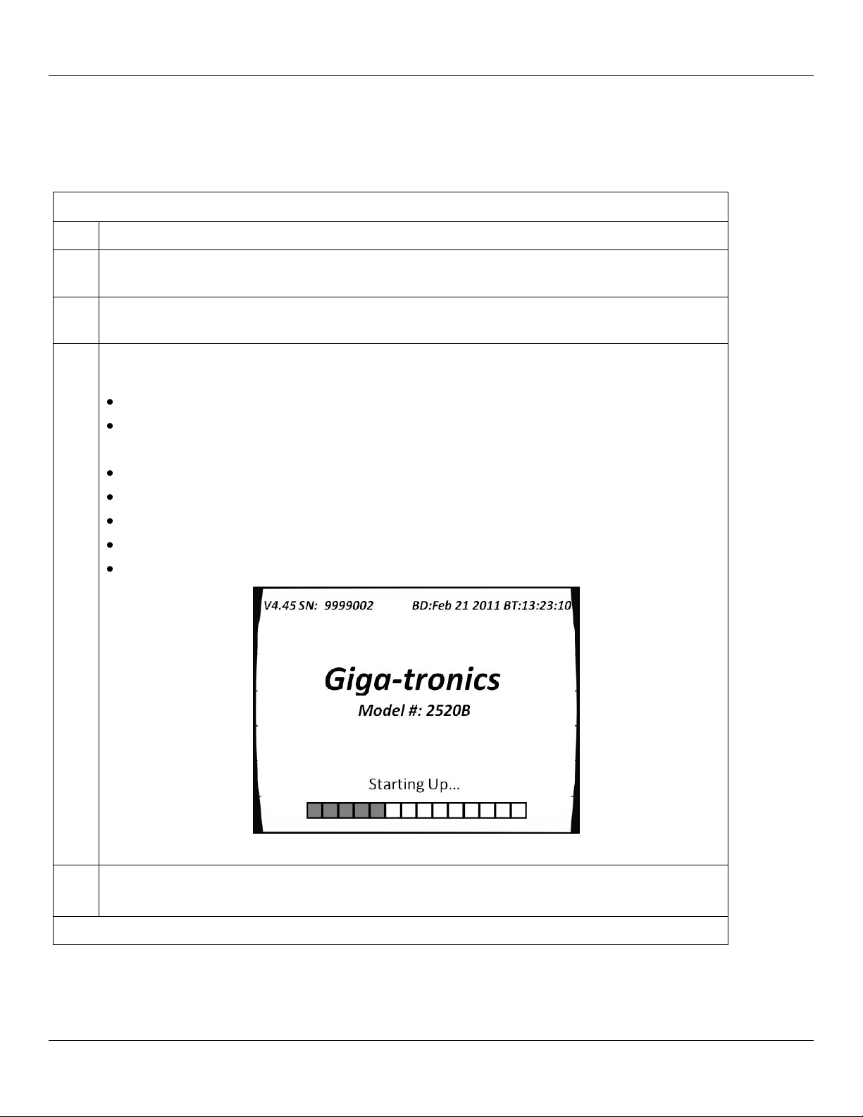
3.
Press the power switch on the front panel of the 2500B. The 2500B displays the following
sequence of screens:
“Initializing” momentarily appears on the display.
The screen shown in Figure 1 appears.
The following information is displayed on the start-up screen:
The firmware version
The serial number of the 2500B
The Build Date (BD) or the firmware version
The Build Time (BT) of the firmware version
A progress bar at the bottom of the screen
Figure 1: 2500B Start Up
4.
Upon the successful conclusion of start-up, the CW Menu is displayed.
If error messages occur during start-up: Refer to page 132.
End of Procedure
2.5.3 Start-up the 2500B
Table 4 below describes how to start-up the 2500B.
Table 4: Start-Up the 2500B
Operation Manual, Part Number 34737, Rev C, June 30, 2011 Page 7

Introduction Giga-tronics 2500B Series Microwave Signal Generators
Reset the 2500B to Default Values
Step
Action
1.
Press the power switch on the front of the 2500B to de-energize the instrument. Wait 5 seconds,
then go to the next step.
2.
Push the power switch in to energize the unit. While the message “INITIALIZING” is displayed,
press and hold the Preset button.
3.
When the “Resetting Memory...” screen is displayed, release the PRESET button.
4.
The system continues to power up normally. All information stored in the memory locations is
cleared, and the system resets to factory default settings.
End of Procedure
2.5.4 Reset the 2500B to Factory-Default Values
The 2500B uses non-volatile memory (NVRAM), which is preserved with a battery for storing the instrument’s current
state, saved setups, and lists. If you want to return these saved settings in NVRAM to the default values they were set to
at the factory, perform the procedure below.
Table 5: Reset the 2500B to Default Values
Page 8 Operation Manual, Part Number 34737, Rev C, June 30, 2011
Giga-tronics 2500B Series Microwave Signal Generators Introduction
Replace the 2500B Line Fuse
Step
Action
1.
Use the power switch on the front of the 2500B to switch the unit into STANDBY.
2.
On the rear of the 2500B, disconnect the AC line cord. The fuse compartment is located to the
left of the AC line cord socket.
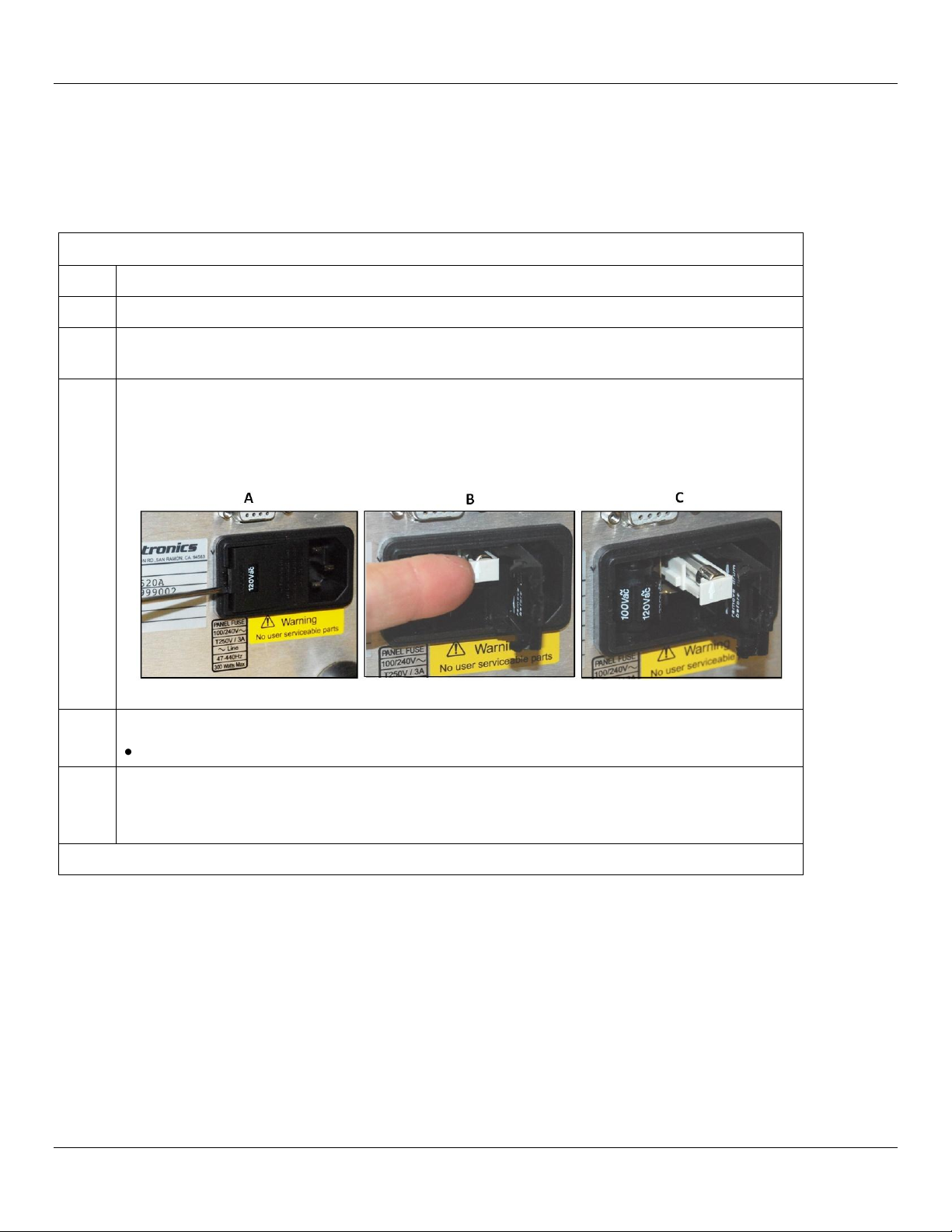
3.
Remove the fuse as follows (see Figure 2):
A) Use a small flat-blade screwdriver to pry open the fuse compartment.
B) Pull out the white fuse holder.
C) You can now remove the fuse from the fuse holder.
Figure 2: 2500B Fuse Holder
4.
Replace the fuse with a new fuse (3 A, Slow-Blow, 250V, Type T).
Push the fuse holder in, and close the fuse compartment door.
5.
Plug the AC line cord into the rear of the 2500B and return the instrument to operation.
NOTE: If the 2500B continues to blow fuses, contact your local Giga-tronics sales representative
or the Giga-tronics factory. See the contact information on page ii of this manual.
End of Procedure
2.5.5 Replace the AC Line Fuse
If the AC line fuse in the 2500B continues to blow, it’s usually an indication of internal problems. If this occurs, contact
Giga-tronics for help (see Table 7 on page 10). Table 6 below describes how to replace the fuse in the 2500B.
Table 6: Replace the 2500B Line Fuse
Operation Manual, Part Number 34737, Rev C, June 30, 2011 Page 9
Introduction Giga-tronics 2500B Series Microwave Signal Generators
Contacting Giga-tronics Customer Service
Email
repairs@gigatronics.com
Telephone (within the United States)
800.726.4442
Telephone
925.328.4669
Fax
925.328.4702
2.6 Shipping, Repair, and Calibration
2.6.1 Shipping the 2500B
If it is necessary to ship the 2500B, observe the following:
Use the best packaging materials available. If possible, reuse the original shipping container.
If the original shipping container is not available, use a strong carton (350 lbs./sq. in. bursting strength) or a wooden
box.
Wrap the instrument in electro-static dissipative material before placing it into the shipping container.
Completely fill the areas on all sides of the instrument with packaging material. Take extra precaution to protect the
front and rear panels.
Seal the package with strong tape or metal bands. Mark the outside of the package clearly, and in bold type, as
follows:
FRAGILE — DELICATE INSTRUMENT
2.6.2 Repairs
The Giga-tronics 2500B microwave signal generator is a robust instrument that has been designed and built for years of
trouble-free service. However, if you experience problems with the instrument, do the following:
1. Contact your local Giga-tronics sales office, or the factory, and be prepared to provide the model, serial number,
and any included options of your instrument, and a description of the problem. To contact the factory directly,
use the following information:
Table 7: Contacting Giga-tronics Customer Service
2. If it is has been determined that you must ship the 2500B to the factory or a service center for repair, you will be
issued a Return Materials Authorization (RMA) number. Use the RMA number in all correspondence regarding
the repair.
3. Pack the 2500B for shipment as described in the previous section, and enclose all relevant information regarding
the problem.
4. Ship the 2500B to the address provided by Giga-tronics Customer Service.
2.6.3 Calibration
Giga-tronics recommends that the 2500B be calibrated every two years. For more information regarding calibration of
your instrument, contact Giga-tronics (see page ii of this manual).
Page 10 Operation Manual, Part Number 34737, Rev C, June 30, 2011
Giga-tronics 2500B Series Microwave Signal Generators Introduction
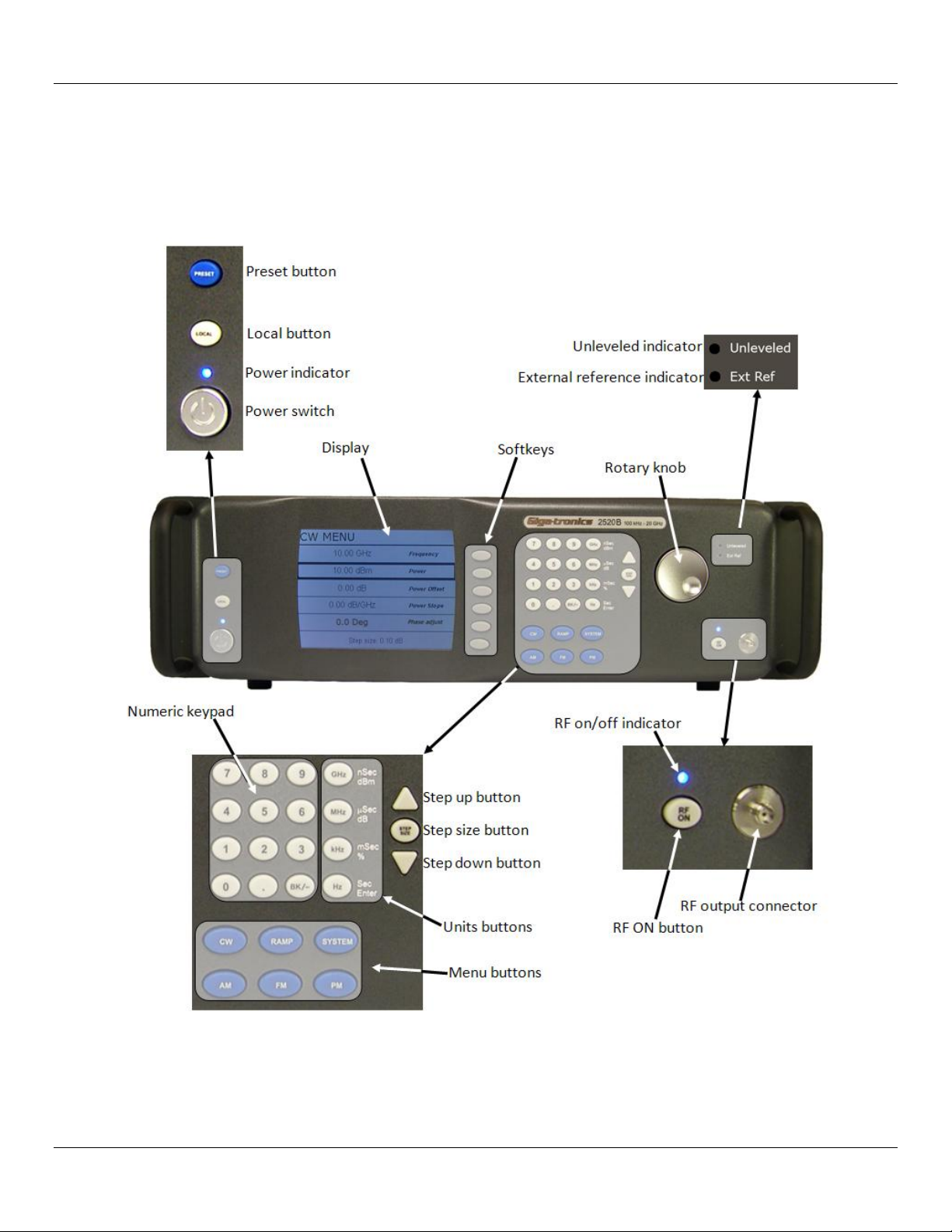
2.7 2500B Front Panel
Figure 3, below, describes the main features of the front panel of the 2500B. Refer to the tables on the following pages
for detailed descriptions of the parts of the front panel.
NOTE: A 2520B is shown in Figure 3. The 2520B front panel is representative of the entire 2500B series.
Figure 3: 2520B Front Panel
Operation Manual, Part Number 34737, Rev C, June 30, 2011 Page 11

Introduction Giga-tronics 2500B Series Microwave Signal Generators
2500B Front Panel
Name
Description
POWER button
Puts the 2500B into one of two states:
STANDBY; power is applied to the internal timebase oscillator. This is to maintain
timebase stability when the 2500B is not in use.
ON; all functions of the 2500B are available for use.
NOTE: To ensure specified performance, allow the 2500B to remain ON or in
STANDBY for at least 30 minutes prior to using the instrument.
POWER indicator
BLUE indicates the instrument is ON and all functions are available.
AMBER indicates the instrument is in STANDBY mode.
LOCAL button
If in REMOTE mode, pressing this button puts the instrument into LOCAL mode.
If the unit is in LOCAL mode: pressing this button displays menus that allow you
to choose the remote command language used during remote operation.
PRESET button
Pressing the PRESET button momentarily presets instrument settings to factory
default values, but does not affect system memory locations, display contrast, or
the GPIB address.
Pressing and holding the PRESET button while the unit is powering up initializes
NVRAM, which includes presetting instrument settings to factory default values
as well as initializing all ten system memory locations, the display contrast, and
the GPIB address.
Display
Displays current instrument settings, and menus for modifying the settings.
The active display is the group of instrument settings and associated menu items
that are currently displayed.
Softkeys
Selects the menu items adjacent to them in the display for modification.
Numeric Keypad
Use for entering numeric settings for generator functions.
STEP SIZE button
Selects and allows editing of the step size by the Step Up/Step Down buttons, rotary
knob, or numeric keypad. To change a step size, see Table 11 on page 18.
RF ON button
Activates RF power output from the 2500B.
Step up/down
buttons
Increases or decreases the selected parameter in the display by the amount specified
by the step size.
Rotary knob
Adjusts the parameter that is selected in the display. When a maximum or minimum
limit is reached, a message appears at the bottom of the display.
Unleveled indicator
When this indicator illuminates, it means that the power output cannot be increased
any further, even though the power output displayed on the front panel may show an
increase. The unleveled point varies with frequency.
External Reference
(Ext Ref) Indicator
Illuminated when the 2500B is operating with an external reference applied.
Table 8: 2500B Front Panel
Page 12 Operation Manual, Part Number 34737, Rev C, June 30, 2011
Giga-tronics 2500B Series Microwave Signal Generators Introduction
2500B Front Panel
Name
Description
RF On/Off Indicator
This indicator has two states:
BLUE indicates the 2500B RF output is active.
NOT illuminated indicates the RF output is not active.
RF Output
The connector type of the RF Output is determined by the upper frequency limit of
the instrument, as follows:
2502B and 2508B: type-N (F)
2520B: SMA (F)
2526B: SMA (F)
2540B: 2.92 mm (F)
2550B: 2.4 mm (F)
NOTE: On some options, the RF output is on the rear panel. Refer to page 130 for
information about all options.
Menu buttons
CW Button
Press this button to display the CW Menu. Shows parameters related to the CW
functions and the Cable Correction functions and their associated menu items.
RAMP Button
Press this button to display either the Ramp Frequency or Ramp Power Menus.
SYSTEM Button
Press this button to display either the System 1 or System 2 menu.
AM Button
Press this button to display the Amplitude Modulation (AM) menus.
FM Button
(Includes phase
modulation menus)
Press this button to display the Frequency Modulation (FM) and Phase Modulation
(ΦM) menus.
PM Button
Press this button to display the Pulse Modulation (PM) menu.
Operation Manual, Part Number 34737, Rev C, June 30, 2011 Page 13
Introduction Giga-tronics 2500B Series Microwave Signal Generators
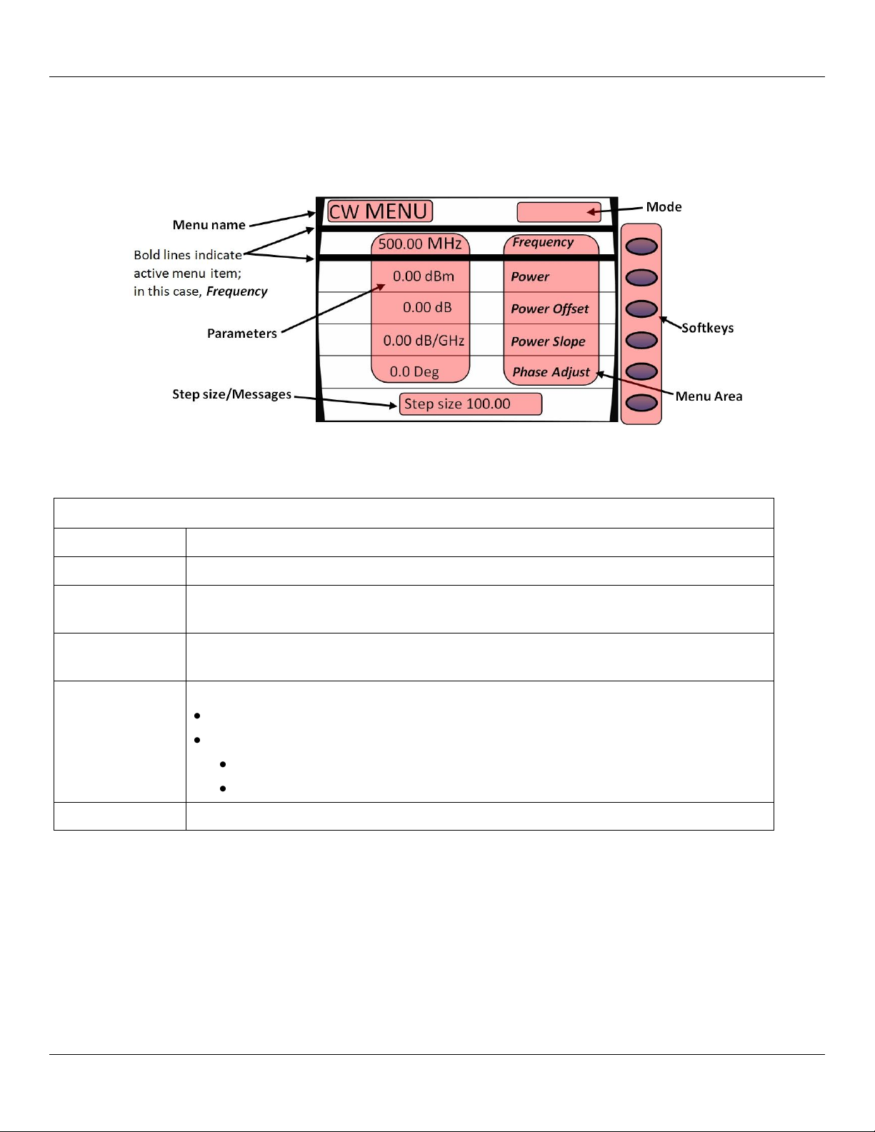
2500B Display Description
Area of Display
Description
Menu Name
Name of the menu that is displayed. This is called the active menu.
Parameters
Displays the current values of the instrument settings associated with the active menu.
Parameters can be modified by the rotary knob or Step Up/Down buttons.
Step
Size/Messages
The step size is the minimum increment by which a parameter can be modified. The step
size can be adjusted. Non-error user messages can also appear in this area.
Menu Area
Displays one of the following:
Submenus
Menu items that can be modified in the active menu.
Menu items are selected (made active) by pressing the adjacent softkey.
The row containing the active parameter has a bold border around it.
Softkeys
Each softkey makes a submenu selectable or parameter active for modification.
2.7.1 Menus
Menus appear on the front panel display of the 2500B. The figure below shows the CW menu to illustrate the common
areas of all menus.
Figure 4: Functional Areas of the 2500B Display
Table 9: 2500B Display Description
Page 14 Operation Manual, Part Number 34737, Rev C, June 30, 2011

Giga-tronics 2500B Series Microwave Signal Generators Introduction
2500B Display Description
Area of Display
Description
Mode
This area may contain one of the following codes:
OFS appears if a power offset greater than 0 dB is set in the CW menu.
SLP appears if a power slope greater than 0 dB/GHz is set in the CW menu.
AM appears if internal or external amplitude modulation is enabled
FM appears if internal or external frequency modulation is enabled
ΦM appears if internal or external phase modulation is enabled
PM appears if internal or external pulse modulation is enabled
EXT LEVEL appears if ALC is set to external
UNLK appears if the Phase Lock Loop is unlocked
OVEN COLD appears if the internal temperature of the 2500B has not reached
operational temperature. It is not recommended to use the 2500B while this indicator is
active.
Operation Manual, Part Number 34737, Rev C, June 30, 2011 Page 15
Introduction Giga-tronics 2500B Series Microwave Signal Generators
AM Ext Menu
Page 37
AM Int Noise Menu
Page 39
AM Int Menu
Page 38
AM
CW
CW MENU
Page 22
FM Ext Menu
Page 45
DC FM Menu
Page 46
FM Int Menu
Page 47
ΦM Ext Menu
Page 48
ΦM Int Menu
Page 49
FM
PM
PM Int Cont Menu
Page 58
PM Int Gated Menu
Page 59
PM Trig Menu
Page 61
PM Burst Menu
Page 63
PM Ext Menu
Page 57
Language Menu 1
Page 83
Language Menu 2
Page 84
Language Menu 3
Page 85
LOCAL
RAMP
Intensity Marker Menu
Page 32
Ramp Freq Start/Stop Sweep Menu
Page 28
Ramp Freq Center/Span Sweep Menu
Page 29
Amplitude Marker Menu
Page 33
SYSTEM
Connectivity Menu
Page 77
Service Menu
Page 78
System Menu
Page 75
Ramp Power Sweep Menu
Page 30
Step Freq Sweep Menu
Page 31
Ethernet Menu
Page 79
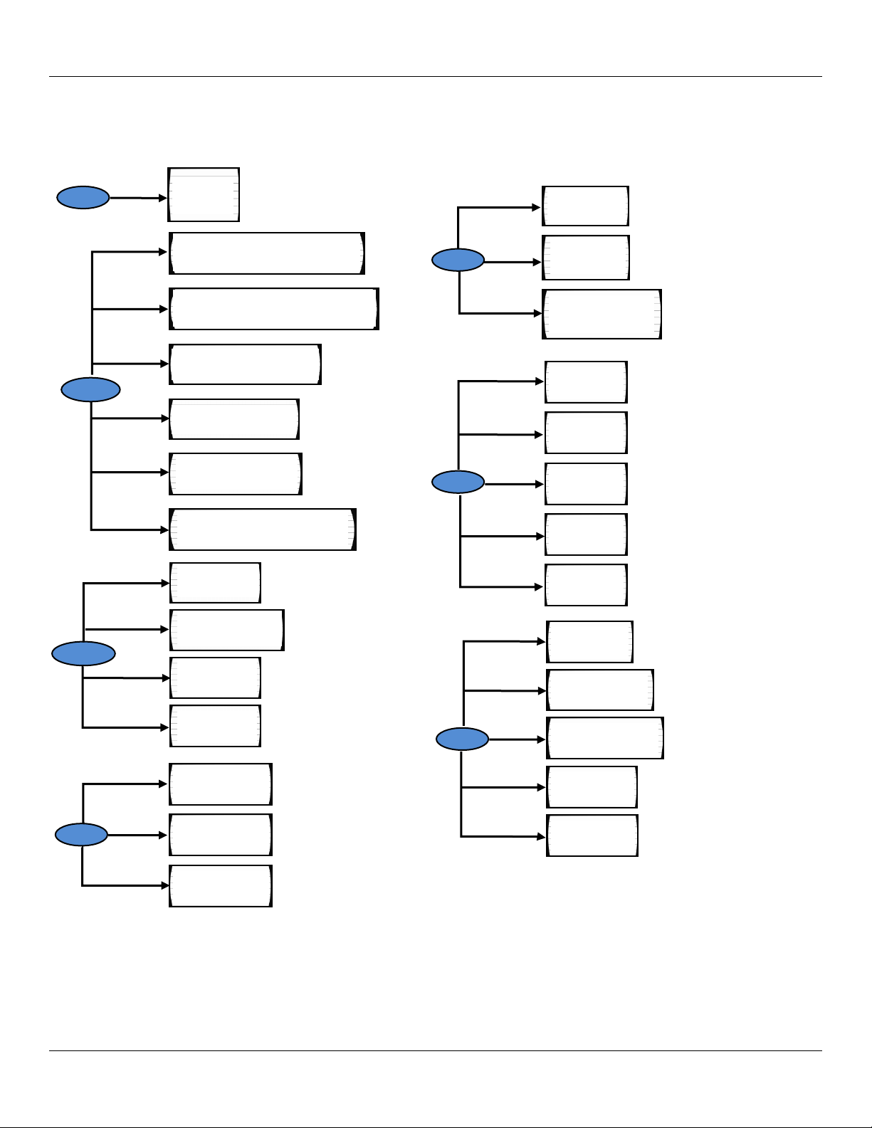
2.7.2 Menu Structure
Figure 5 below shows the structure of the menus of the 2500B. To access the menus, you must first press one of the
blue Menu buttons (see Figure 3 on page 11).
Page 16 Operation Manual, Part Number 34737, Rev C, June 30, 2011
Figure 5: Structure of the 2500B Menus

Giga-tronics 2500B Series Microwave Signal Generators Introduction
Modify a Menu Parameter
Step
Action
1.
Press the softkey adjacent to the parameter you want to modify. Note that the parameter
becomes enclosed in a bold outline box when it is selected.
2.
Modify the value of the parameter by using , , or the numeric keypad (except where
otherwise noted).
End of Procedure
2.7.3 Access the Menus
In local operation, the 2500B menus are accessed via the Menu buttons or Local button on the front panel (see
Figure 3 on page 11). Pressing a Menu button causes the menu for that button to appear on the display. The Menu
buttons are:
o CW
o Ramp
o System
o AM
o FM; includes phase modulation (ΦM) menus
o PM
The LOCAL button allows you to access and modify communication functions during remote operation of the 2500B
(see Figure 3 on page 11).
2.7.4 Softkeys
Use the softkeys (see Figure 4 on page 14) to select a submenu or parameter shown to the left of the softkey, in the
display.
Pressing a softkey next to a submenu displays the submenu and makes its parameters available for viewing and
modification.
Pressing a softkey next to a parameter makes it active for modification.
2.7.5 Modify Menu Parameters
Parameters in the Menu Area of the display (see Figure 4 on page 14) can be modified using either the rotary knob, Step
Up/Down keys, or the numeric keypad (see Figure 3 on page 11), except where otherwise noted. Table 10 below
describes how to modify a menu parameter.
Table 10: Modify a Menu Parameter
Operation Manual, Part Number 34737, Rev C, June 30, 2011 Page 17

Introduction Giga-tronics 2500B Series Microwave Signal Generators
Change the Step Size of a Parameter
Step
Action
1.
Use a softkey to select a parameter. For example, in the CW menu, select Frequency.
2.
Press the Step Size button (see Figure 3 on page 11).
3.
Enter a new step size using the numeric keypad.
4.
Press the appropriate Units button (see Figure 3 on page 11).
5.
Press the Step Size button to save the new step size. Now, when you change the CW frequency using
the Step Up/Step Down buttons or the rotary knob, the parameter changes according to the new Step
Size.
End of Procedure
2.7.6 Modify the Step Size
The step size for a parameter can be modified as described below.
Table 11: Change the Step Size of a Parameter
Page 18 Operation Manual, Part Number 34737, Rev C, June 30, 2011
Giga-tronics 2500B Series Microwave Signal Generators Introduction
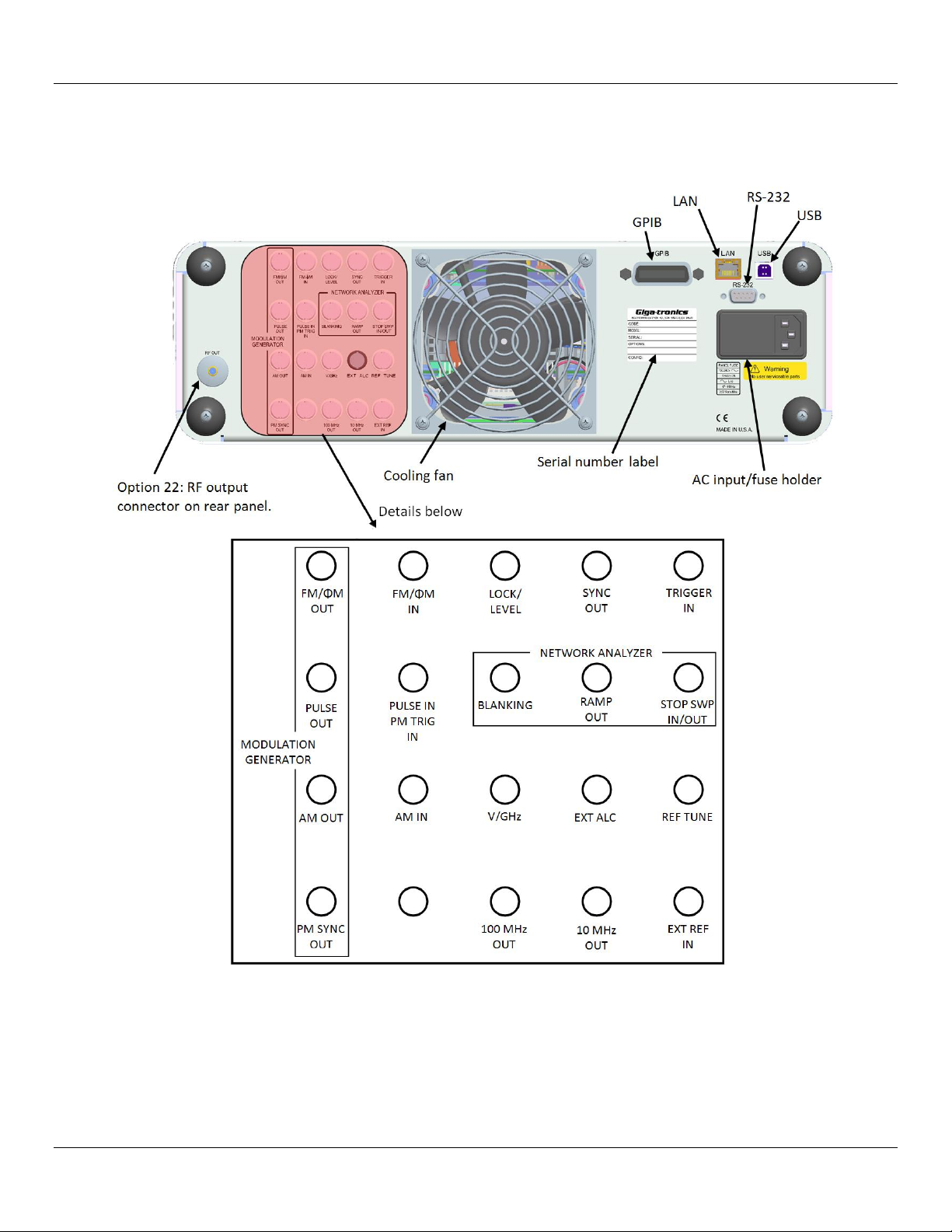
2.8 2500B Rear Panel
Figure 6 below shows the locations of the components on the 2500B rear panel. Descriptions of the rear panel
components are on the following pages.
Figure 6: 2500B Rear Panel
Operation Manual, Part Number 34737, Rev C, June 30, 2011 Page 19

Introduction Giga-tronics 2500B Series Microwave Signal Generators
2500B Rear Panel
Name
Description
EXT ALC
In external leveling, the RF output of the 2500B is detected by either a positive or
negative crystal detector, or power meter with an analog output. The signals from
these devices are connected to the ALC circuitry of the 2500B, which is used to
compensate for standing wave effects or cable and component losses at the input of
the device under test.
MODULATION GENERATOR
FM/φΜ OUT
The internal modulation generator output; 2 Vpp into 10 kΩ.
PULSE OUT
A +4 V video representation of the pulsed RF output signal.
AM OUT
The internal modulation generator output; 2 Vp-p into 10 kΩ.
PM SYNC OUT
A synchronization output pulse of > 75 ns width, TTL levels that can be delayed
relative to the leading edge of the video signal at the PULSE OUT connector.
Limits of delay: ≥ 50 ns, ≤ 10 ms.
FM/φM IN
A 50 Ω input for an external FM or φM modulating signal. The input signal can be
any waveform compatible with bandwidth considerations. A 1-V peak input
produces maximum deviation. Maximum input is ± 1 V p-p.
An externally supplied DC signal can be applied to this input to modulate the
frequency of the CW output.
AM IN
A 600 Ω input for an external AM signal. The input signal can be any waveform
compatible with bandwidth considerations. Maximum input is ± 1 V p-p.
PULSE IN
PM TRIG IN
A Pulse Modulation Input for external Pulse In. The input parameters are:
TTL, polarity selectable, 50 Ω characteristic impedance, 2 kΩ pull-up.
LOCK/LEVEL
+5 Volt output, active high when the 2500B is phase locked and output leveled. The
Lock and Level indicator is valid for CW and List mode.
REF TUNE
A 0 to +10 Volts, high-impedance input for tuning the internal reference in order to
adjust the output frequency approximately +5 ppm. Do not exceed
+15 Volts or apply a negative voltage greater than -1 Volt.
SYNC OUT
In List mode, the unit can be set to generate a pulse at this output when a specified list
point is reached. The RF output can be delayed from the start of the list point up to a
maximum of 10 ms. The pulse width of the SYNC OUT signal is determined as follows:
Pulse width = Step Time - Sync Delay - 10 µs.
In Ramp operation, the pulse occurs at the start of each ramp sweep. In either case,
the output pulse is +5 Volts.
TRIGGER IN
Triggers a List. Accepts a TTL level signal of > 50 ns width.
Table 12: 2500B Rear Panel
Page 20 Operation Manual, Part Number 34737, Rev C, June 30, 2011
 Loading...