

Page 1
Giga-tronics 2400 and 2500 Series Microwave Signal Generators
2400 and 2500 Series
Microwave Signal Generators
Programming Manual, Part Number 34783, Rev A, July 2009
Programming Manual
Page 2

Giga-tronics 2400 and 2500 Series Microwave Signal Generators
tronics 2400/2500 Series instruments are warranted
nd workmanship for one year from
tronics will at its option repair or replace
products that are proven defective during the warranty period.
This warranty DOES NOT cover damage resulting from improper
tronics service. There is
no implied warranty of fitness for a particular purpose, nor is
tronics liable for any consequential damages. Specification
All technical data and specifications in this publication are subject to change without prior notice and do
not represent a commitment on the part of Giga-tronics, Incorporated.
© 2009 Giga-tronics Incorporated. All rights reserved. Printed in the U.S.A.
Gigaagainst defective materials a
date of shipment. Giga-
use, nor workmanship other than Giga-
Gigaand price change privileges are reserved by Giga-tronics.
CONTACT INFORMATION
Giga-tronics, Incorporated
4650 Norris Canyon Road
San Ramon, California 94583
Telephone: 800.726.4442 (only within the United States)
925.328.4650
Fax: 925.328.4700
On the Internet: www.gigatronics.com
Warranty
Programming Manual, Part Number 34783, Rev A, July 2009
Page 3

Giga-tronics 2400 and 2500 Series Microwave Signal Generators
Regulatory Compliance Information
This product complies with the essential requirements of the following applicable European
Directives, and carries the CE mark accordingly.
89/336/EEC and 73/23/EEC EMC Directive and Low Voltage Directive
EN61010-1 (1993) Electrical Safety
EN61326-1 (1997) EMC – Emissions and Immunity
Manufacturer’s Name: Manufacturer’s Address
Giga-tronics, Incorporated 4650 Norris Canyon Road
San Ramon, California 94583
U.S.A.
Type of Equipment: Model Series Number
Microwave Signal Generator 2400 Series
2500 Series
Model Numbers:
2408C, 2420C, 2426C,
2440C
2508B, 2520B, 2526B,
2540B, 2550B
Declaration of Conformity on file. Contact Giga-tronics at the following;
Giga-tronics, Incorporated
4650 Norris Canyon Road
San Ramon, California 94583
Telephone: 800.726.4442 (only within the United States)
925.328.4650
Fax: 925.328.4700
Programming Manual, Part Number 34783, Rev A, July 2009
Page 4
Giga-tronics 2400 and 2500 Series Microwave Signal Generators
Record of changes to this Manual
Use the table below to maintain a permanent record of changes to this document. Replacement pages
will be issued as a TPCI (Technical Publication Change Instruction), and will be inserted at the front of
the binder. Remove the corresponding old pages, insert the new pages, and record the changes here. Do
the same thing with TCPI pages that are issued after you have received this manual.
TPCI Number TPCI Issue Date Date Entered Comments
Programming Manual, Part Number 34783, Rev A, July 2009
Page 5

Giga-tronics 2400 and 2500 Series Microwave Signal Generators
Table of Contents
Table of Contents...........................................................................................................................................i
Chapter 1. Safety ....................................................................................................................................1
1.1 Unsafe Operating Conditions........................................................................................................1
1.2 Safety Warnings Used in This Manual ..........................................................................................1
1.2.1 Personal Safety Alert.............................................................................................................1
1.2.2 Equipment Safety Alert.........................................................................................................1
1.2.3 Notes.....................................................................................................................................1
Chapter 2. Introduction ..........................................................................................................................3
2.1 Overview.......................................................................................................................................3
2.2 Physical Description of the 2400/2500.........................................................................................4
Chapter 3. Hardware Interfaces .............................................................................................................5
3.1 Introduction ..................................................................................................................................5
3.2 Configure the 2400/2500 Hardware Interface .............................................................................6
3.2.1 Using the Included USB Cable...............................................................................................6
3.2.2 Assign a GPIB Address to the 2400/2500..............................................................................6
3.2.3 Configure the Computer’s RS-232 for Remote Operation....................................................6
3.2.4 Configure the 2400/2500 Ethernet Connection ...................................................................7
Chapter 4. Programming Interfaces .......................................................................................................9
4.1 Introduction ..................................................................................................................................9
4.2 Select the Remote Programming Language..................................................................................9
4.3 Dynamic Link Library (DLL)..........................................................................................................10
4.3.1 Adding the DLL to Programming Projects...........................................................................10
4.3.2 Programming Examples Using the DLL ...............................................................................11
4.3.3 DLL Functions ......................................................................................................................17
4.4 SCPI Command Set......................................................................................................................96
4.4.1 SCPI Command Format .......................................................................................................96
4.4.2 SCPI Commands ..................................................................................................................97
4.5 IEEE 488.2 Common Commands...............................................................................................120
4.6 GT-12000 Native Commands ....................................................................................................122
4.6.1 GT-12000 Native Commands: CW and System.................................................................122
4.6.2 GT-12000 Native Commands: List Mode ..........................................................................123
4.6.3 GT-12000 Native Commands: Amplitude Modulation .....................................................125
4.6.4 GT-12000 Native Commands: Frequency Modulation .....................................................126
4.6.5 GT-12000 Native Commands: Phase Modulation.............................................................127
4.6.6 GT-12000 Native Commands: Pulse Modulation..............................................................128
4.7 Emulation..................................................................................................................................129
4.7.1 HP 834X Emulation Commands ........................................................................................129
Programming Manual, Part Number 34783, Rev A, July 2009 i
Page 6

Giga-tronics 2400 and 2500 Series Microwave Signal Generators
4.7.2 HP 8663 Emulation Commands ........................................................................................132
4.7.3 HP 8673 Emulation Commands ........................................................................................134
4.7.4 HP 8360 Emulation Commands ........................................................................................138
4.7.5 HP 8370 Emulation Commands ........................................................................................139
4.7.6 GT900 Emulation Commands ...........................................................................................140
4.7.7 Option 55F: Wavetek 90X Emulation Commands.............................................................142
4.7.8 Systron Donner 16XX Emulation Commands....................................................................143
Chapter 5. Automation Xpress............................................................................................................149
5.1 Introduction ..............................................................................................................................149
5.1.1 Benefits of Using Automation Xpress ...............................................................................149
5.2 Install Automation Xpress.........................................................................................................150
5.3 Start Automation Xpress...........................................................................................................152
5.4 Automation Xpress GUI Description .........................................................................................154
5.4.1 Tool Bar .............................................................................................................................155
5.4.2 Indicators and RF Button...................................................................................................165
5.5 Auto Programmer .....................................................................................................................167
5.5.1 Introduction ......................................................................................................................167
5.5.2 Auto Programmer Examples.............................................................................................168
Chapter 6. Status Register System......................................................................................................171
6.1 Introduction ..............................................................................................................................171
6.2 Status Byte and Service Request Enable Registers ...................................................................173
6.3 Standard Event Status and Standard Event Status Enable Registers........................................174
6.4 Questionable Status Condition and Enable Registers...............................................................175
Chapter 7. 2400/2500 Specific Commands ........................................................................................177
Chapter 8. List Mode Operation .........................................................................................................179
Chapter 9. LabVIEW Drivers................................................................................................................181
9.1 Overview...................................................................................................................................181
9.2 LabVIEW Drivers........................................................................................................................183
9.2.1 LabVIEW Drivers for DLL Functions...................................................................................183
9.2.2 Non-DLL LabVIEW Drivers.................................................................................................187
Appendix A. Remote Error Messages....................................................................................................189
Appendix B. DLL Error Messages...........................................................................................................193
Appendix C. FM Sensitivity/Deviation RangeTable ...............................................................................197
ii Programming Manual, Part Number 34783, Rev A, July 2009
Page 7
Giga-tronics 2400 and 2500 Series Microwave Signal Generators 1. Safety
Chapter 1. Safety
1.1 Unsafe Operating Conditions
If you notice any of the following conditions while operating electronics equipment, IMMEDIATELY
de-energize the equipment.
• The instrument fails to operate normally, or operates erratically.
• The power cable, receptacle, or plug on the instrument is damaged
• The instrument causes electrical shock or operates at abnormally high temperature.
• A liquid or foreign substance falls into the instrument
• The instrument generates an abnormal sound, smell, smoke, or sparking light.
If any of the above conditions occurs, contact Giga-tronics to get the instrument repaired.
WARNING
cause death or serious damage to the instrument and any equipment connected to it.
Continuing to operate the instrument with any of the above conditions could
1.2 Safety Warnings Used in This Manual
1.2.1 Personal Safety Alert
WARNING: Indicates a hazardous situation which, if not avoided, could result in
WARNING
death or serious injury.
1.2.2 Equipment Safety Alert
CAUTION
CAUTION: Indicates a situation which can damage or adversely affect the 2400 and 2500
or associated equipment.
1.2.3 Notes
Notes are denoted and used as follows:
NOTE: Highlights or amplifies an essential operating or maintenance procedure, practice,
condition or statement.
Programming Manual, Part Number 34783, Rev A, July 2009 1
Page 8

1. Safety Giga-tronics 2400 and 2500 Series Microwave Signal Generators
This page is intentionally blank
2 Programming Manual, Part Number 34783, Rev A, July 2009
Page 9

Giga-tronics 2400 and 2500 Series Microwave Signal Generators 2. Introduction
Chapter 2. Introduction
2.1 Overview
Manual Convention:
• For simplicity, when generically referring to Giga-tronics Microwave Signal Generators in the
2400 and 2500 Series, the term “2400/2500” may be used. Specific models within either series
are referred to when necessary.
This manual describes how to program and remotely control the 2400/2500 and 2500B Series
Microwave Signal Generators for automated testing.
Giga-tronics designed the 2400/2500 for high performance and flexibility, and accordingly, there are
different ways to set up the instrument for automated testing. All methods for setting up the 2400/2500
for automated testing are described in this manual.
However, the easiest and most effective way to use the 2400/2500 for automated testing is through
Automation Xpress, an automated testing application developed by Giga-tronics that is included on the
CD-ROM that shipped with the 2400/2500.
Automation Xpress provides the fastest switching of power and frequency during automated testing.
This maximizes device throughput, keeping your testing costs as low as possible.
Features of Automation Xpress:
• 1.0 ms frequency and power switching during testing
• Eliminate the need to learn GPIB or other native language commands by using the Auto
Programming feature, which automatically records a sequence of actions and converts those
actions into program code. You can then import this code into the program environment of your
choice, such as Visual C++ or Visual Basic.
• The Xpress Auto-programming feature virtually eliminates training time by providing scripts and
sequences guaranteed for accuracy.
• Transit and execution times for single-function calls such as changing CW frequency are ten
times faster using Automation Xpress compared to standard message-based commands.
• Automation Xpress sends large amounts of data (i.e., large lists) more than 100 times faster than
SCPI commands.
Programming Manual, Part Number 34783, Rev A, July 2009 3
Page 10

2. Introduction Giga-tronics 2400 and 2500 Series Microwave Signal Generators
2.2 Physical Description of the 2400/2500
If you need information about the controls, indicators, display, or any other physical aspects of the
2400/2500, refer to the Operation Manual for the series you are interested in:
2400/2500 Operation Manual part number: 34802
2500B Operation Manual part number: 34737
4 Programming Manual, Part Number 34783, Rev A, July 2009
Page 11
Giga-tronics 2400/2500 Series Microwave Signal Generators 3. Hardware Interfaces
GPIB
RS-232
USB
LAN
Chapter 3. Hardware Interfaces
3.1 Introduction
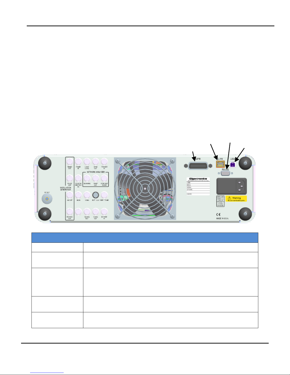
The 2400/2500 has four connectors to choose from for connecting to a computer:
• GPIB
• LAN (Ethernet)
• RS-232
• USB
Figure 1 below shows the locations of the connectors on the 2400/2500 rear panel. Descriptions of the
connectors are given in Table 1 below.
NOTE: Your 2400/2500 may look slightly different, depending on series and model.
Figure 1. 2400/2500 Rear Panel
Table 1 2400/2500 Hardware Interfaces Description
Name Description
GPIB A 24-pin IEEE STD 488.2 connector for control of the instrument during remote
operation using GPIB.
RS-232 A DB-9 connector for control of the instrument during remote operation using
RS-232 serial communications. A USB to Serial Cable Port Adapter is included
with the 2400/2500 for controlling the instrument via the USB port on a host
computer.
USB A USB connector for control of the instrument during remote operation using
USB 2.0 (full speed) communications
Ethernet An Ethernet connector for control of the instrument during remote operation
using LAN interface communications.
Programming Manual, Part Number 34783, Rev A, July 2009 5
Page 12
3. Hardware Interfaces Giga-tronics 2400/2500 Series Microwave Signal Generators
SYSTEM
3.2 Configure the 2400/2500 Hardware Interface
3.2.1 Using the Included USB Cable
A USB 2.0 Type A Male to Type B Male cable shipped with the 2400/2500, and provides you with the
simplest way to connect a computer to the 2400/2500. The cable connects between a USB port on the
computer, and the USB port on the 2400/2500.
To use this cable, you must first install Automation Xpress and the USB driver on the computer. See
Table 40 on page 150.
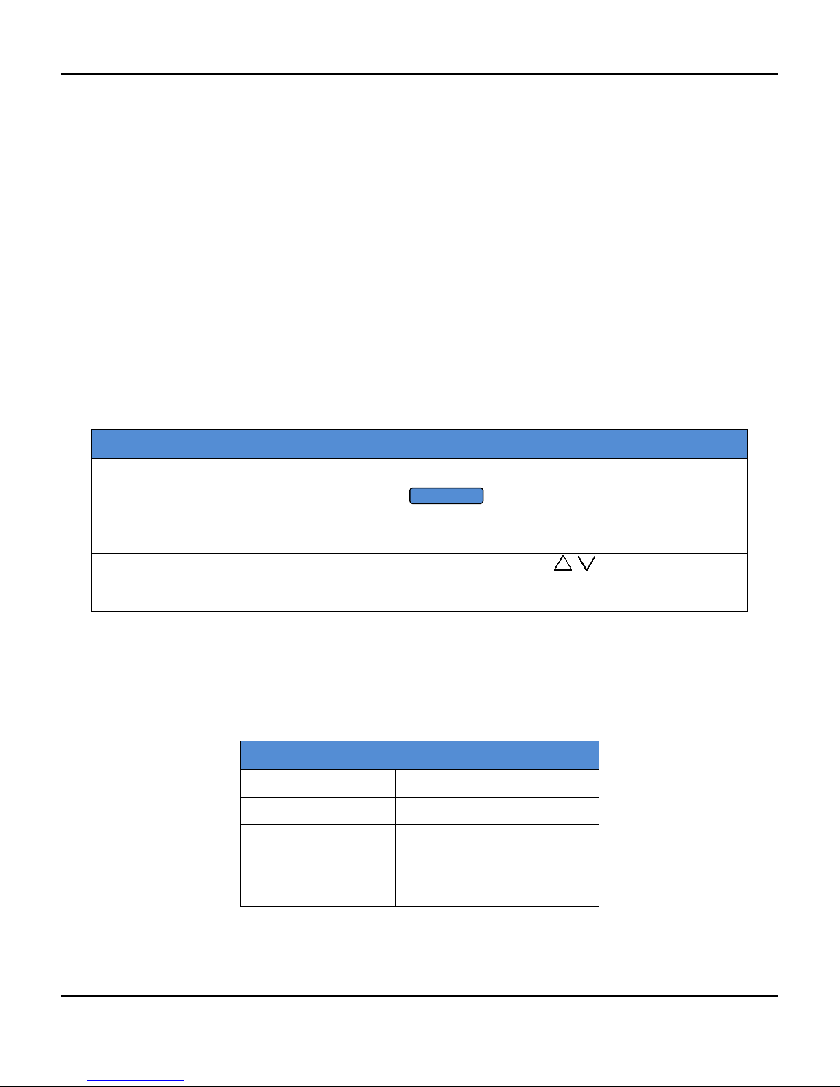
3.2.2 Assign a GPIB Address to the 2400/2500
To connect a computer to the 2400/2500 via GPIB, the 2400/2500 must be assigned a GPIB address. The
procedure below describes how to assign a GPIB address to a 2400/2500.
Table 2 Setup GPIB Address
Step Action
1.
On the front panel of the 2400/2500, press to display the System menus, and if the
SYSTEM 2 menu does not appear in the display, press the bottom-most interactive softkey until it
does.
2.
Enter the desired GPIB address using either the numeric keypad or .
End of Procedure
3.2.3 Configure the Computer’s RS-232 for Remote Operation
Table 3 below gives information for configuring an RS-232 port on a computer to communicate with the
2400/2500.
Table 3 RS-232 Communication Settings
Baud rate 115200
Data Bits 8
Parity None
Stop bits 1
Handshake None
6 Programming Manual, Part Number 34783, Rev A, July 2009
Page 13
Giga-tronics 2400/2500 Series Microwave Signal Generators 3. Hardware Interfaces
SYSTEM
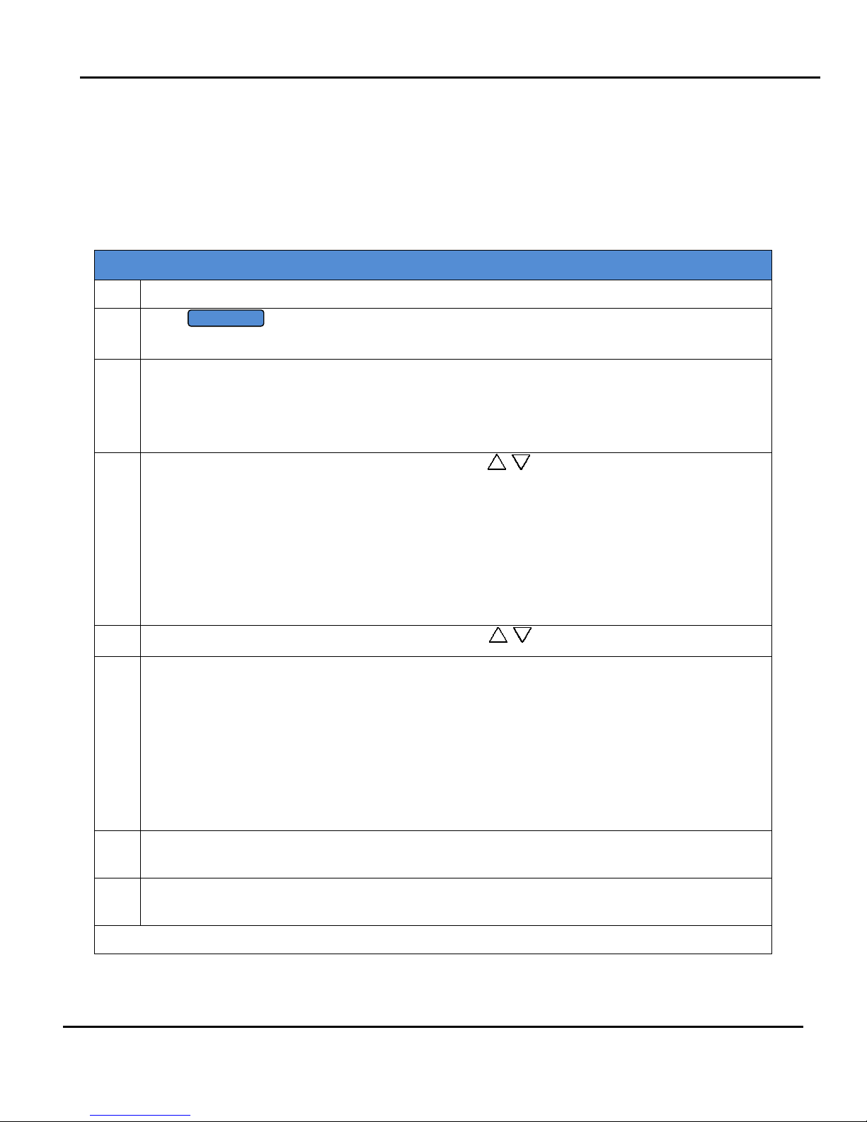
3.2.4 Configure the 2400/2500 Ethernet Connection
The following procedure explains how to set the DHCP, IP Address, and Subnet Mask of the 2400/2500
when using the Ethernet (LAN) connector on the rear of the 2400/2500. The instrument is identified via
Ethernet connection during remote operations using the IP address set in this procedure. Each unit on
the network must have a unique IP address.
Table 4 Configure Remote Operation Using the LAN
Step Action
1.
Press to invoke the System menus, and if the SYSTEM 4 menu does not appear in
the display, press the bottom-most interactive softkey until it does.
2. Are you going to connect the LAN using Dynamic Host Configuration Protocol (DHCP), or
configure the LAN connection manually?
If the LAN connection will be done by DHCP: go to the next step.
If the LAN connection will be configured manually: go to Step 4.
3.
Press the DHCP softkey and set DCHP to On using the keys. The instrument will try to
connect to the DCHP server and the IP address and Subnet Mask will be set automatically from
the first server that establishes communication via the LAN connection.
Go to Step 7.
NOTE: If the 2400/2500 fails to connect to the DCHP server, the unit will attempt to reconnect
again. If it fails to connect to the DCHP server a second time, the 2400/2500 will attempt to
reconnect once every hour. During this period, the IP address and subnet mask values will be
zero.
4.
Press the DHCP softkey and set DCHP to Off using the keys.
5. Press the IP Address softkey to highlight the IP Address menu item. Enter the IP address using the
numeric keypad.
NOTE: An IP address consists of four sets of three-digit numbers, separated by decimal points.
The following example demonstrates how to properly enter an IP address:
190.165.001.034
An invalid IP entry will be displayed as Invalid IP Input in the Step Size/Error Message section of
the display. Examples of invalid addresses are values greater than 255, less than zero (negative
sign), values greater than three digits per set or more or less than 4 sets of three-digit values.
6. Press the Subnet Mask softkey to highlight the Subnet Mask menu item. Enter the subnet mask
number using the sequence defined in the previous step.
7. Confirm that the server has connected to 2400/2500 by observing the Link Status menu item.
This menu item is an indicator only. No entry key functions are processed.
End of Procedure
Programming Manual, Part Number 34783, Rev A, July 2009 7
Page 14

3. Hardware Interfaces Giga-tronics 2400/2500 Series Microwave Signal Generators
This page is intentionally blank
8 Programming Manual, Part Number 34783, Rev A, July 2009
Page 15

Giga-tronics 2400/2500 Microwave Synthesizer Series 4. Programming Interfaces
Chapter 4. Programming Interfaces
4.1 Introduction
This chapter describes the different programming interfaces and methods for remotely controlling a
2400/2500.
4.2 Select the Remote Programming Language
The 2400/2500 can communicate using a variety of languages. Every 2400/2500 is capable of
communications using the SCPI (Standard Commands for Programmable Instruments) language or any
Giga-tronics native command set. Optional Command Sets are available as well.
Table 5 below describes how to use the 2400/2500 front panel in local operating mode to select a
language from the Language Menu.
Table 5 Select the Remote Language
Step Action
1.
• If the instrument IS NOT in remote operating mode, press the LOCAL button once to invoke
the Language menus in the display.
• If the instrument IS IN remote operating mode, press the LOCAL button twice - once to take
it out of remote operating mode, then again to invoke the Language menus in the display.
2. If the desired language does not appear in the parameter area of the display, press the bottommost interactive softkey to go to the next menu. There are three screens for the Language
menus. Use the bottom softkey to go through the screens until you find the language you want
to use.
3. If the message “Option not installed” appears next to a given language in the menu area of the
display, that language is optional and not currently available in the instrument. Contact Gigatronics customer support to inquire about purchasing additional language options.
4. Once you have located the desired language, press the associated interactive softkey in the
display to select it.
End of Procedure
Programming Manual, Part Number 34783, Rev A, July 2009 9
Page 16

4. Programming Interfaces Giga-tronics 2400/2500 Microwave Synthesizer Series
4.3 Dynamic Link Library (DLL)
A DLL is a collection of routines that can be used by applications or other DLLs. A DLL is provided on the
CD-ROM that is included with the 2400/2500 Microwave Signal Generator. When you install Automation
Xpress from the CD-ROM onto your computer, the DLL is loaded onto your computer. The routines in
the DLL can be used in Visual C++, Visual Basic, and other applications.
4.3.1 Adding the DLL to Programming Projects
The following procedures describe how to include the DLL into Visual C++ and Visual Basic projects.
4.3.1.1 Add the DLL to a Visual C++ Project
Table 6 Add the DLL to a Visual C++ Project
Step Action
1. Create a Visual C++ project.
2. Copy GT2400.dll from C:\Program Files\Giga-tronics\AX\bin into your project’s executable folder
for run time calls. (e.g. folder named “Debug”)
3. Copy GT2400.lib from C:\Program Files\Giga-tronics\AX\lib into your project.
4. Copy all files from C:\Program Files\Giga-tronics\AX\include into your project.
5. Copy the following line into your application C/C++ files:
“#include “GT2400.h”
6. Make DLL function calls as needed from any .cpp files where GT2400.h file is included.
7. Build your application.
End of Procedure
4.3.1.2 Add the DLL to a Visual Basic Project
Table 7 Add the DLL to a Visual Basic Project
Step Action
1. Create a Visual Basic project.
2. Copy GT2400.dll from C:\Program Files\Giga-tronics\AX\bin into your project’s executable folder
for run time calls.
3. Copy DLLDeclare.bas from C:\Program Files\Giga-tronics\AX\VBModule to the project folder.
4. Make DLL function calls as needed from any files in the project.
5. Build the application.
10 Programming Manual, Part Number 34783, Rev A, July 2009
End of Procedure
Page 17

Giga-tronics 2400/2500 Microwave Synthesizer Series 4. Programming Interfaces
4.3.2 Programming Examples Using the DLL
4.3.2.1 CW Operation Using Visual C++
NOTE: Only bold faced code lines are unique to a specific operation mode. All other lines are supporting
lines shared by both CW and List modes.
Step Description
1.
Perform steps 1 through 5 in Table 6 on page 10 to add the DLL to a Visual C++ project.
2.
Write the following code:
#include "GT2400.h"
#include "stdio.h"
#define SUCCESS 0
//This routine sets CW frequency and power of a 2400/2500
synthesizer
//at your choice through GPIB at address 6.
void main(void)
{
STATUS status;
unsigned long instrumentHandle;
double Frequency = 1000;
double Power = 0;
status = GT2400_OpenConnection(0,6,0,&instrumentHandle);
if(status < SUCCESS )
{
char statusText[256];
GT2400_GetErrorMessage(status, statusText);
printf("Status Message %s\n",statusText);
}
status = GT2400_SetRF(instrumentHandle, 1);
printf("Frequency (MHz) =");
scanf("%lf",&Frequency);
printf("Power (dBm) =");
scanf("%lf",&Power);
status = GT2400_SetCW(instrumentHandle,Frequency,Power,0,0);
status = GT2400_CloseAllConnections();
}
3.
Build the project.
4.
Run the program.
Programming Manual, Part Number 34783, Rev A, July 2009 11
End of Example
Page 18

4. Programming Interfaces Giga-tronics 2400/2500 Microwave Synthesizer Series
4.3.2.2 Programming Example; CW Operation Using Visual Basic
Step Description
1.
Perform steps 1 through 3 of Table 7 on page 10 to create a Visual Basic project.
2.
Write the following
‘This routine sets CW frequency and power of a 2400/2500
synthesizer
‘through GPIB at address 6.
Dim status As Long
Dim instrumentHandle As Long
Dim Frequency As Double
Dim Power As Double
Dim statusText As String
statusText = Space(100)
status = GT2400_OpenConnection(0,6,0,instrumentHandle)
If status < SUCCESS Then
GT2400_GetErrorMessage(status, statusText)
MsgBox statusText
End If
status = GT2400_SetRF(instrumentHandle, 1)
Frequency = 20000 ‘MHz
Power = 10
status = GT2400_SetCW(instrumentHandle,Frequency,Power,0,0)
status = GT2400_CloseAllConnections()
3.
Build the project.
4.
Run the program.
12 Programming Manual, Part Number 34783, Rev A, July 2009
End of example
Page 19

Giga-tronics 2400/2500 Microwave Synthesizer Series 4. Programming Interfaces
4.3.2.3 Programming Example; List Operation Using Visual C++
Step Description
1.
Perform steps 1 through 5 of Table 6 to create a Visual C++ project.
2. Write the following code:
#include <windows.h>
#include <stdio.h>
#include "gt2400.h"
#define SUCCESS 0
//This routine can load any list file to 2400/2500 synthesizer
//and set up repeat type and trigger type at user choice.
void main(void)
{
long status;
char listFileName[80];
char statusText[256];
unsigned long instrumentHandle;
short tmp;
status = GT2400_OpenConnection(0, 6, 0, &instrumentHandle);
if(status < SUCCESS )
{
GT2400_GetErrorMessage(status, statusText);
printf("Status Message %s\n",statusText);
}
printf("Please enter the file name to be loaded:\n ");
scanf("%s",&listFileName);
status = GT2400_LoadListFromFile(listFileName, statusText);
if ( status < SUCCESS ) //Error during loading
{
GT2400_GetErrorMessage(status, statusText);
printf("Status Message %s\n",statusText);
}
status = GT2400_DownloadList(instrumentHandle, listFileName);
printf("Enter Repeat Type (0 = single step; 1 = single sweep; 2 = continuous) =");
scanf("%d",&tmp);
status = GT2400_SetRepeatType(instrumentHandle, tmp);
printf("Enter Trigger Type (0 = External trigger; 1 = Software trigger or GET) =");
scanf("%d",&tmp);
status = GT2400_SetTriggerType(instrumentHandle, tmp);
status = GT2400_SetRF(instrumentHandle, 1);
status = GT2400_CloseAllConnections();
}
Continued next page
Programming Manual, Part Number 34783, Rev A, July 2009 13
Page 20

4. Programming Interfaces Giga-tronics 2400/2500 Microwave Synthesizer Series
Step Description
3.
Build the project.
4.
Run the program.
5.
Send trigger.
End of example
14 Programming Manual, Part Number 34783, Rev A, July 2009
Page 21

Giga-tronics 2400/2500 Microwave Synthesizer Series 4. Programming Interfaces
4.3.2.4 Programming Example; Generate Two Frequencies
The following example shows how to write code for generating two CW frequencies, separated by a 40
second delay.
Step Description
//This example sets two CW frequencies in sequence, separated by a 40 second delay.
1.
#include "GT2400.h"
#include "stdio.h"
#include "winbase.h"
void main(void)
{
long STATUS;
unsigned long instrumentHandle;
printf("f= 23.456789 MHz, Power = 5 dBm\n");
STATUS = GT2400_OpenConnection(0, 6, 0, &instrumentHandle);
STATUS = GT2400_SetRF(instrumentHandle, 1);
STATUS = GT2400_SetCW(instrumentHandle, 23.456789, 5);
printf("Waiting for 40 seconds....\n");
//Reserve time for frequency counter to operate correctly
Sleep(40000);
printf("f= 33.4567891 MHz, Power = 0 dBm\n");
STATUS = GT2400_SetCW(instrumentHandle, 33.4567891, 0);
STATUS = GT2400_CloseAllConnections();
}
End of example
Programming Manual, Part Number 34783, Rev A, July 2009 15
Page 22

4. Programming Interfaces Giga-tronics 2400/2500 Microwave Synthesizer Series
4.3.2.5 Programming Example: List Operation Using Visual Basic
Step Description
1. Perform step 1 through step 3 of Table 7 on page 10 to create a Visual Basic project.
2. Write following:
‘This routine can load any list file to 2400/2500 synthesizer
‘and set up repeat type and trigger type.
Dim status As Long
Dim listFileName As String
Dim statusText As String
Dim instrumentHandle As Long
statusText = Space(100)
status = GT2400_OpenConnection(0, 6, 0, instrumentHandle)
If status < SUCCESS Then
GT2400_GetErrorMessage(status, statusText)
MsgBox statusText
End If
‘Please replace C:\Temp\ListTest.txt with your list file name.
listFileName = “C:\Temp\ListTest.txt”
status = GT2400_LoadListFromFile(listFileName, listFileName)
If status < SUCCESS Then
‘Error during loading
GT2400_GetErrorMessage(status, statusText)
MsgBox statusText
End If
status = GT2400_DownloadList(instrumentHandle, listFileName)
‘Repeat Type (0 = single step; 1 = single sweep; 2 = continuous) =")
status = GT2400_SetRepeatType(instrumentHandle, 1)
‘ Trigger Type (0 = External trigger; 1 = Software trigger or GET) =")
status = GT2400_SetTriggerType(instrumentHandle, 0)
status = GT2400_SetRF(instrumentHandle, 1)
status = GT2400_CloseAllConnections()
3. Build the project.
4. Run the program.
5. Send trigger.
16 Programming Manual, Part Number 34783, Rev A, July 2009
End of example
Page 23

Giga-tronics 2400/2500 Microwave Synthesizer Series 4. Programming Interfaces
4.3.3 DLL Functions
This section describes the DLL functions in detail.
Programming Manual, Part Number 34783, Rev A, July 2009 17
Page 24

4. Programming Interfaces Giga-tronics 2400/2500 Microwave Synthesizer Series
4.3.3.1 DLL Function; GT2400_FindInstruments
GT2400_FindInstruments
Purpose
Find the addresses of instruments, either through GPIB or RS232, connected to PC.
Syntax
STATUS GT2400_FindInstruments( const short connectionType,
short addresses[],
short *pCount)
Parameter Description
connectionType Input: Connection type.
0 = GPIB,
1 = RS232
2,3 = SPECIAL (NOT FOR COMMON USE)
4 = GPIB Connection via remote SERVER PC (TCP/IP)
addresses Output: Array of GPIB addresses or COM port numbers of all the Giga-tronics
instruments connected.
(Note: In case the RS232 connection interface is selected, the first element returned
in this array is the first serial port that is connected to a Giga-tronics instrument
followed by the remaining serial port numbers on the PC.)
Example 1:
There are total of 4 COM ports on a PC, and only COM port 1 is connected to a Gigatronics instrument, the returned result will be
addresses[0] = 1
addresses[1] = 2
addresses[2] = 3
addresses[3] = 4
Example 2:
There are total of 4 COM ports on a PC, and only COM port 3 is connected to a Gigatronics instrument, the returned result will be
addresses[0] = 3
addresses[1] = 4
pCount Output: Total number of instruments connected to PC through the specified
interface.
18 Programming Manual, Part Number 34783, Rev A, July 2009
Page 25

Giga-tronics 2400/2500 Microwave Synthesizer Series 4. Programming Interfaces
4.3.3.2 DLL Function; GT2400_OpenConnection
GT2400_OpenConnection
Purpose
Establish the communication between the PC and the 2400/2500 with the specified connection interface
and address. For an Ethernet connection, call GT2400_SetIPAddress function first to establish the
TCP/IP address of the instrument.
Syntax
STATUS GT2400_OpenConnection( const short connectionType,
const short address,
const short resetDevice
unsigned long *instrumentHandle)
Parameter Description
connectionType Input: Connection interface:
0 = GPIB
1 = RS232
2,3 = SPECIAL (NOT FOR COMMON USE)
4 = GPIB Connection via remote SERVER PC (TCP/IP) (not supported after Revision
3.3)
5 = reserved
6 = Ethernet (TCP/IP) (supported from Rev 3.3)
address Input: GPIB address number if ConnectionType = 0
or COM port number if ConnectionType = 1
Note: GPIB communication board index can be set if GPIB interface is selected. The
2 byte (SHORT) “address” contains GPIB board index and address. The most
significant byte is used to set GPIB board index and the least significant byte is used
to set GPIB address. The default GPIB board index is 0.
Example: GPIB board index = 1; GPIB address = 6
Parameter, address = 0x100 | 0x6 =
0x106 (in Hex.) or 262 (in Decimal)
resetDevice Input:
1 = Reset instrument in start up
0 = No reset
instrumentHandle Output: The unique identification of the connected instrument. This handle can be
used later to operate on multiple instruments.
Programming Manual, Part Number 34783, Rev A, July 2009 19
Page 26

4. Programming Interfaces Giga-tronics 2400/2500 Microwave Synthesizer Series
4.3.3.3 DLL Function; GT2400_CloseGPIBConnection
GT2400_CloseGPIBConnection
Purpose
Close one specific GPIB connection.
Syntax
STATUS GT2400_CloseGPIBConnection( const unsigned long instrumentHandle)
Parameter Description
instrumentHandle Input: The unique identification of the connected instrument.
20 Programming Manual, Part Number 34783, Rev A, July 2009
Page 27

Giga-tronics 2400/2500 Microwave Synthesizer Series 4. Programming Interfaces
4.3.3.4 DLL Function; GT2400_CloseAllConnections
GT2400_CloseAllConnections
Purpose
Close all connection. You should always call this function before you close your application to avoid
memory leak.
Syntax
STATUS GT2400_CloseAllConnections(void)
Programming Manual, Part Number 34783, Rev A, July 2009 21
Page 28

4. Programming Interfaces Giga-tronics 2400/2500 Microwave Synthesizer Series
4.3.3.5 DLL Function; GT2400_SetGPIBAddress
GT2400_SetGPIBAddress
Purpose
Set the GPIB address.
Syntax
STATUS GT2400_SetGPIBAddress( const unsigned long instrumentHandle,
const short address,
unsigned long *updatedInstrumentHandle)
Parameter Description
instrumentHandle Input: The unique identification of the instrument.
address Input: GPIB address.
updatedInstrumentHandle Output: Updated instrument handle after this function completes.
22 Programming Manual, Part Number 34783, Rev A, July 2009
Page 29

Giga-tronics 2400/2500 Microwave Synthesizer Series 4. Programming Interfaces
4.3.3.6 DLL Function; GT2400_SetServerIPAddr (for Rev 3.0 and above)
GT2400_SetServerIPAddr (for Rev 3.0 and above)
Purpose
Set the TCP/IP address of remote SERVER PC. (example: 194.177.0.482)
Syntax
STATUS GT2400_SetServerIPAddr( char ipAddr[])
Parameter Description
ipAddr Input: TCP/IP address of remote SERVER PC
Programming Manual, Part Number 34783, Rev A, July 2009 23
Page 30

4. Programming Interfaces Giga-tronics 2400/2500 Microwave Synthesizer Series
4.3.3.7 DLL Function; GT2400_GetIPAddress (supported from Revision 3.3)
GT2400_GetIPAddress (supported from Revision 3.3)
Purpose
Get the TCP/IP address of the instrument. (example: 194.177.0.482).
Syntax
STATUS GT2400_GetIPAddress( char ipAddr[])
Parameter Description
ipAddr Output: TCP/IP address for the instrument
24 Programming Manual, Part Number 34783, Rev A, July 2009
Page 31

Giga-tronics 2400/2500 Microwave Synthesizer Series 4. Programming Interfaces
4.3.3.8 DLL Function; GT2400_SetIPAddress (supported from Revision 3.3)
GT2400_SetIPAddress (supported from Revision 3.3)
Purpose
Set the TCP/IP address for the instrument. (example: 194.177.0.482) For establishing Ethernet
connection with the instrument, this function needs to be called prior to calling
GT2400_OpenConnection function.
Syntax
STATUS GT2400_SetIPAddress( char ipAddr[])
Parameter Description
ipAddr Input: TCP/IP address for the instrument
Programming Manual, Part Number 34783, Rev A, July 2009 25
Page 32

4. Programming Interfaces Giga-tronics 2400/2500 Microwave Synthesizer Series
4.3.3.9 DLL Function; GT2400_ResetInstrument
GT2400_ResetInstrument
Purpose
Reset the instrument to factory defaults.
Syntax
STATUS GT2400_ResetInstrument( const unsigned long instrumentHandle)
Parameter Description
instrumentHandle Input: The unique identification of the instrument
26 Programming Manual, Part Number 34783, Rev A, July 2009
Page 33

Giga-tronics 2400/2500 Microwave Synthesizer Series 4. Programming Interfaces
4.3.3.10 DLL Function; GT2400_GetRF
GT2400_GetRF
Purpose
Get the state of RF output
Syntax
STATUS GT2400_GetRF( const unsigned long instrumentHandle,
short *RFState)
Parameter Description
instrumentHandle Input: The unique identification of the instrument
RFState Output:
1 = RF is on
0 = RF is off
Programming Manual, Part Number 34783, Rev A, July 2009 27
Page 34

4. Programming Interfaces Giga-tronics 2400/2500 Microwave Synthesizer Series
4.3.3.11 DLL Function; GT2400_SetRF
GT2400_SetRF
Purpose
Set the RF on or off.
Syntax
STATUS GT2400_SetRF( const unsigned long instrumentHandle,
const short RFState)
Parameter Description
instrumentHandle Input: The unique identification of the instrument
RFState Input:
1 = Turn on
0 = Turn off RF output
28 Programming Manual, Part Number 34783, Rev A, July 2009
Page 35

Giga-tronics 2400/2500 Microwave Synthesizer Series 4. Programming Interfaces
4.3.3.12 DLL Function; GT2400_GetAttenuation
GT2400_GetAttenuation
Purpose
Get the attenuation value.
Syntax
STATUS GT2400_GetAttenuation( const unsigned long instrumentHandle,
short *pAttenuation)
Parameter Description
instrumentHandle Input: The unique identification of the instrument.
pAttenuation Output: current attenuation in the instrument.
If returned value = -10, it is in AUTO attenuation mode;
Else If returned value = -99, there is no attenuator option installed;
Else attenuation is in MANUAL mode with value = *pAttenuation
Programming Manual, Part Number 34783, Rev A, July 2009 29
Page 36

4. Programming Interfaces Giga-tronics 2400/2500 Microwave Synthesizer Series
4.3.3.13 DLL Function; GT2400_SetAttenuation
GT2400_SetAttenuation
Purpose
Set the attenuation of the output power of the 2400/2500.
Syntax
STATUS GT2400_SetAttenuation( const unsigned long instrumentHandle,
const short attenuation)
Parameter Description
instrumentHandle Input: The unique identification of the instrument
attenuation Input: attenuation value, e.g.
If attenuation = -10, set to auto attenuation;
Else If attenuation >= 0, set to manual attenuation with value = attenuation.
attenuation = [0, 10,20,30,40,50,60,70,80,90]
30 Programming Manual, Part Number 34783, Rev A, July 2009
Page 37

Giga-tronics 2400/2500 Microwave Synthesizer Series 4. Programming Interfaces
4.3.3.14 DLL Function; GT2400_GetALCLeveling
GT2400_GetALCLeveling
Purpose
Get the current ALC leveling source of the instrument.
Syntax
STATUS GT2400_GetALCLeveling( const unsigned long instrumentHandle,
short *alcLeveling)
Parameter Description
instrumentHandle Input: The unique identification of the instrument
alcLeveling Output: Current ALC leveling source of the instrument
= 0: Internal
= 1: Power Meter
= 2: Positive Diode
= 3: Negative
Programming Manual, Part Number 34783, Rev A, July 2009 31
Page 38

4. Programming Interfaces Giga-tronics 2400/2500 Microwave Synthesizer Series
4.3.3.15 DLL Function; GT2400_SetALCLeveling
GT2400_SetALCLeveling
Purpose
Set the ALC leveling source to the instrument.
Syntax
STATUS GT2400_SetALCLeveling( const unsigned long instrumentHandle,
const short alcLeveling)
Parameter Description
instrumentHandle Input: The unique identification of the instrument
alcLeveling Input: ALC leveling source set to the instrument
= 0: Internal
= 1: Power Meter
= 2: Positive Diode
= 3: Negative
32 Programming Manual, Part Number 34783, Rev A, July 2009
Page 39

Giga-tronics 2400/2500 Microwave Synthesizer Series 4. Programming Interfaces
4.3.3.16 DLL Function; GT2400_GetErrorMessage
GT2400_GetErrorMessage
Purpose
Convert STATUS code to the corresponding description.
Syntax
STATUS GT2400_GetErrorMessage( const long errorID,
char statusText[])
Parameter Description
errorID STATUS of any DLL function
statusText Text description of the STATUS
Programming Manual, Part Number 34783, Rev A, July 2009 33
Page 40

4. Programming Interfaces Giga-tronics 2400/2500 Microwave Synthesizer Series
4.3.3.17 DLL Function; GT2400_GetDLLVersion
GT2400_GetDLLVersion
Purpose
Return the DLL version.
Syntax
STATUS GT2400_GetDLLVersion( char version[])
Parameter Description
version DLL version
34 Programming Manual, Part Number 34783, Rev A, July 2009
Page 41

Giga-tronics 2400/2500 Microwave Synthesizer Series 4. Programming Interfaces
4.3.3.18 DLL Function; GT2400_GetCW
GT2400_GetCW
Purpose
Read the current CW setting (data) from the instrument.
Syntax
STATUS GT2400_GetCW( const unsigned long instrumentHandle,
double *frequency,
double *power)
Parameter Description
instrumentHandle Input: The unique identification of the instrument
frequency Output: CW frequency (in MHz)
power Output: CW power (in dBm)
Programming Manual, Part Number 34783, Rev A, July 2009 35
Page 42

4. Programming Interfaces Giga-tronics 2400/2500 Microwave Synthesizer Series
4.3.3.19 DLL Function; GT2400_GetCWDataLimit
GT2400_GetCWDataLimit
Purpose
Get the CW data limits of the instrument.
Syntax
STATUS GT2400_GetCWDataLimit( const unsigned long instrumentHandle,
double *pMinFrequency,
double *pMaxFrequency,
double *pMinPower,
double *pMaxPower)
Parameter Description
instrumentHandle Input: The unique identification of the instrument
pMinFrequency Output: Minimum frequency allowed (in MHz)
pMaxFrequency Output: Maximum frequency allowed (in MHz)
pMinPower Output: Minimum power allowed (in dBm)
pMaxPower Output: Maximum power allowed (in dBm)
36 Programming Manual, Part Number 34783, Rev A, July 2009
Page 43

Giga-tronics 2400/2500 Microwave Synthesizer Series 4. Programming Interfaces
4.3.3.20 DLL Function; GT2400_SetCW
GT2400_SetCW
Purpose
Set CW.
Syntax
STATUS GT2400_SetCW( const unsigned long instrumentHandle,
const double frequency,
const double power)
Parameter Description
instrumentHandle Input: The unique identification of the instrument
frequency Input: CW frequency (in MHz)
power Input: CW power (in dBm)
Programming Manual, Part Number 34783, Rev A, July 2009 37
Page 44

4. Programming Interfaces Giga-tronics 2400/2500 Microwave Synthesizer Series
4.3.3.21 DLL Function; GT2400_GetPowerOffset
GT2400_GetPowerOffset
Purpose
Get the current power offset value of the instrument.
Syntax
STATUS GT2400_GetPowerOffset( const unsigned long instrumentHandle,
double *powerOffset)
Parameter Description
instrumentHandle Input: The unique identification of the instrument
powerOffset Output: Current power offset value of the instrument
38 Programming Manual, Part Number 34783, Rev A, July 2009
Page 45

Giga-tronics 2400/2500 Microwave Synthesizer Series 4. Programming Interfaces
4.3.3.22 DLL Function; GT2400_SetPowerOffset
GT2400_SetPowerOffset
Purpose
Set the power offset value to the instrument.
Syntax
STATUS GT2400_SetPowerOffset( const unsigned long instrumentHandle,
const double powerOffset)
Parameter Description
instrumentHandle Input: The unique identification of the instrument
powerOffset Input: Power offset value set to the instrument
Programming Manual, Part Number 34783, Rev A, July 2009 39
Page 46

4. Programming Interfaces Giga-tronics 2400/2500 Microwave Synthesizer Series
4.3.3.23 DLL Function; GT2400_GetPowerSlope
GT2400_GetPowerSlope
Purpose
Get the current power slope value of the instrument.
Syntax
STATUS GT2400_GetPowerSlope( const unsigned long instrumentHandle,
double *powerSlope)
Parameter Description
instrumentHandle Input: The unique identification of the instrument
powerSlope Output: Current power slope value of the instrument
40 Programming Manual, Part Number 34783, Rev A, July 2009
Page 47

Giga-tronics 2400/2500 Microwave Synthesizer Series 4. Programming Interfaces
4.3.3.24 DLL Function; GT2400_SetPowerSlope
GT2400_SetPowerSlope
Purpose
Set the power slope value to the instrument.
Syntax
STATUS GT2400_SetPowerSlope( const unsigned long instrumentHandle,
const double powerSlope)
Parameter Description
instrumentHandle Input: The unique identification of the instrument
powerSlope Input: Power slope value set to the instrument
Programming Manual, Part Number 34783, Rev A, July 2009 41
Page 48

4. Programming Interfaces Giga-tronics 2400/2500 Microwave Synthesizer Series
4.3.3.25 DLL Function; GT2400_DownloadList
GT2400_DownloadList
Purpose
Download a list to the GT2400 synthesizer. The file can be prepared beforehand by either MS Excel, or
any text editor or AutomationXpress GUI or AutomationXpress DLL list editing functions.
Syntax
STATUS GT2400_DownloadList( const unsigned long instrumentHandle,
const char listPath[])
Parameter Description
instrumentHandle Input: The unique identification of the instrument
listPath Input: Complete path (path + list name) of the list being downloaded to the unit
42 Programming Manual, Part Number 34783, Rev A, July 2009
Page 49

Giga-tronics 2400/2500 Microwave Synthesizer Series 4. Programming Interfaces
4.3.3.26 DLL Function; GT2400_GetRepeatType
GT2400_GetRepeatType
Purpose
Get the repeat type of the list to be triggered.
Syntax
STATUS GT2400_GetRepeatType( const unsigned long instrumentHandle,
short *repeatType)
Parameter Description
instrumentHandle Input: The unique identification of the instrument
repeatType Output:
0 = single step;
1 = single sweep;
2 = continuous
Programming Manual, Part Number 34783, Rev A, July 2009 43
Page 50

4. Programming Interfaces Giga-tronics 2400/2500 Microwave Synthesizer Series
4.3.3.27 DLL Function; GT2400_SetRepeatType
GT2400_SetRepeatType
Purpose
Set the repeat type of the list to be triggered.
Syntax
STATUS GT2400_SetRepeatType( const unsigned long instrumentHandle,
const short repeatType)
Parameter Description
instrumentHandle Input: The unique identification of the instrument
repeatType Input:
0 = single step;
1 = single sweep;
2 = continuous
44 Programming Manual, Part Number 34783, Rev A, July 2009
Page 51

Giga-tronics 2400/2500 Microwave Synthesizer Series 4. Programming Interfaces
4.3.3.28 DLL Function; GT2400_GetTriggerType
GT2400_GetTriggerType
Purpose
Get the trigger type to trigger the list.
Syntax
STATUS GT2400_GetTriggerType( const unsigned long instrumentHandle,
short *triggerType)
Parameter Description
instrumentHandle Input: The unique identification of the instrument
triggerType Output:
0 = External trigger;
1 = GET;
2 = Software trigger
Programming Manual, Part Number 34783, Rev A, July 2009 45
Page 52

4. Programming Interfaces Giga-tronics 2400/2500 Microwave Synthesizer Series
4.3.3.29 DLL Function; GT2400_SetTriggerType
GT2400_SetTriggerType
Purpose
Set the trigger type to trigger the list.
Syntax
STATUS GT2400_SetTriggerType( const unsigned long instrumentHandle,
const short triggerType)
Parameter Description
instrumentHandle Input: The unique identification of the instrument
triggerType Input:
0 = External trigger;
1 = GET;
2 = Software trigger
46 Programming Manual, Part Number 34783, Rev A, July 2009
Page 53

Giga-tronics 2400/2500 Microwave Synthesizer Series 4. Programming Interfaces
4.3.3.30 DLL Function; GT2400_SetListScanDirection
GT2400_SetListScanDirection
Purpose
Set the list scan direction.
Syntax
STATUS GT2400_SetListScanDirection( const unsigned long instrumentHandle,
const short direction)
Parameter Description
instrumentHandle Input: The unique identification of the instrument.
direction Input:
0 = scan from first point to last point;
1 = scan from last to first.
Programming Manual, Part Number 34783, Rev A, July 2009 47
Page 54

4. Programming Interfaces Giga-tronics 2400/2500 Microwave Synthesizer Series
4.3.3.31 DLL Function; GT2400_SoftwareTrigger
GT2400_SoftwareTrigger
Purpose
Use the software to trigger the current list.
Syntax
STATUS GT2400_SoftwareTrigger( const unsigned long instrumentHandle)
Parameter Description
instrumentHandle Input: The unique identification of the instrument
48 Programming Manual, Part Number 34783, Rev A, July 2009
Page 55

Giga-tronics 2400/2500 Microwave Synthesizer Series 4. Programming Interfaces
4.3.3.32 DLL Function; GT2400_GroupExecutionTrigger
GT2400_GroupExecutionTrigger
Purpose
Send a Group Execution Trigger (G.E.T. is defined in IEEE 488) to all the instruments connected to PC via
GPIB.
Syntax
STATUS GT2400_GroupExecutionTrigger( void)
Programming Manual, Part Number 34783, Rev A, July 2009 49
Page 56

4. Programming Interfaces Giga-tronics 2400/2500 Microwave Synthesizer Series
4.3.3.33 DLL Function; GT2400_GetListDataLimit
GT2400_GetListDataLimit
Purpose
Get the list data limits of the instrument.
Syntax
STATUS GT2400_GetListDataLimit( const unsigned long instrumentHandle,
short *pMaxListPts,
double *pMinStepTime,
double *pMaxStepTime,
double *pMinRFOffTime,
double *pMaxRFOffTime,
double *pMinSyncOutDelay,
double *pMaxSyncOutDelay)
Parameter Description
instrumentHandle Input: The unique identification of the instrument.
pMaxListPts Output: Maximum number of list points
pMinStepTime Output: Minimum list step time (in ms)
pMaxStepTime Output: Maximum list step time (in ms)
pMinRFOffTime Output: Minimum list RF off time (in ms)
pMaxRFOffTime Output: Maximum list RF off time (in ms)
pMinSyncOutDelay Output: Minimum list sync out delay (in ms)
pMaxSyncOutDelay Output: Maximum list sync out delay (in ms)
50 Programming Manual, Part Number 34783, Rev A, July 2009
Page 57

Giga-tronics 2400/2500 Microwave Synthesizer Series 4. Programming Interfaces
4.3.3.34 DLL Function; GT2400_LoadListFromFile
GT2400_LoadListFromFile
Purpose
Load a list from a disk file to PC RAM.
Syntax
STATUS GT2400_LoadListFromFile( const char filename[],
char errText[])
Parameter Description
filename Input: Name of the file being loaded.
errText Output: If there is an error detected by STATUS, errText will hold the description
of the problems.
Programming Manual, Part Number 34783, Rev A, July 2009 51
Page 58

4. Programming Interfaces Giga-tronics 2400/2500 Microwave Synthesizer Series
4.3.3.35 DLL Function; GT2400_CreateNewList
GT2400_CreateNewList
Purpose
Create a new list in PC RAM.
Syntax
STATUS GT2400_CreateNewList( const char listPath[])
Parameter Description
listPath Input: Complete path (path + list name) of the list whose content is requested
52 Programming Manual, Part Number 34783, Rev A, July 2009
Page 59

Giga-tronics 2400/2500 Microwave Synthesizer Series 4. Programming Interfaces
4.3.3.36 DLL Function; GT2400_SaveListToFile
GT2400_SaveListToFile
Purpose
Save a currently active list from RAM to a disk file.
Syntax
STATUS SaveListToFile ( const char filename[],
char errText[])
Parameter Description
filename Input: File name of list to be saved in.
errText Output: If there is an error detected by STATUS, errText will hold the description
of the problems.
Programming Manual, Part Number 34783, Rev A, July 2009 53
Page 60

4. Programming Interfaces Giga-tronics 2400/2500 Microwave Synthesizer Series
4.3.3.37 DLL Function; GT2400_ActivateAList
GT2400_ActivateAList
Purpose
Activate the selected list so that the list is ready to respond to a trigger.
Syntax
STATUS GT2400_ActivateAList( const char listPath[])
Parameter Description
listPath Input: Complete path (path + list name) of the list to be activated
54 Programming Manual, Part Number 34783, Rev A, July 2009
Page 61

Giga-tronics 2400/2500 Microwave Synthesizer Series 4. Programming Interfaces
4.3.3.38 DLL Function; GT2400_GetListData
GT2400_GetListData
Purpose
Get the contents of the selected list from DLL allocated RAM into user application.
Syntax
STATUS GT2400_GetListData( const char listPath[],
double *stepTime,
double *rfOffTime,
double *syncOutDelay,
unsigned char *syncInfo,
short *attenSetting
double *frequency,
double *power,
short *pListLen)
Parameter Description
listPath Input: Complete path (path + list name) of the list whose content is requested.
stepTime Output: Step time of all list points (in ms)
rfOffTime Output: RF off time of all list points (in ms)
syncOutDelay Output: Sync out delay (in ms)
syncInfo Output: Sync out pulse information for every list pt
attenSetting Output: The attenuation setting for the current list
frequency Output: Array of frequencies in the list (in MHz)
power Output: Array of power in the list (in dBm)
pListLen Output: Number of points in the list
Programming Manual, Part Number 34783, Rev A, July 2009 55
Page 62

4. Programming Interfaces Giga-tronics 2400/2500 Microwave Synthesizer Series
4.3.3.39 DLL Function; GT2400_GetListDataWithCorrection
GT2400_GetListDataWithCorrection
Purpose
Get the contents of the selected list from DLL allocated RAM into user application.
Syntax
STATUS GT2400_GetListDataWithCorrection ( const char listPath[],
double *stepTime,
double *rfOffTime,
double *syncOutDelay,
unsigned char *syncInfo,
short *attenSetting
double *frequency,
double *power,
double *correction,
short *pListLen)
Parameter Description
listPath Input: Complete path (path + list name) of the list whose content is requested.
stepTime Output: Step time of all list points (in ms)
rfOffTime Output: RF off time of all list points (in ms)
syncOutDelay Output: Sync out delay (in ms)
syncInfo Output: Sync out pulse information for every list pt
attenSetting Output: The attenuation setting for the current list
frequency Output: Array of frequencies in the list (in MHz)
power Output: Array of power in the list (in dBm)
correction Output: Array of correction in the list (in dBm)
pListLen Output: Number of points in the list
56 Programming Manual, Part Number 34783, Rev A, July 2009
Page 63

Giga-tronics 2400/2500 Microwave Synthesizer Series 4. Programming Interfaces
4.3.3.40 DLL Function; GT2400_SetCorrection
GT2400_SetCorrection
Purpose
Edit the correction of the selected list.
Syntax
STATUS GT2400_SetCorrection ( double *correction)
Parameter Description
correction Input: Array of correction
Programming Manual, Part Number 34783, Rev A, July 2009 57
Page 64

4. Programming Interfaces Giga-tronics 2400/2500 Microwave Synthesizer Series
4.3.3.41 DLL Function; GT2400_GetCorrection
GT2400_GetCorrection
Purpose
Get the correction of the selected list.
Syntax
STATUS GT2400_GetCorrection ( double *correction)
Parameter Description
correction Output: Array of correction
58 Programming Manual, Part Number 34783, Rev A, July 2009
Page 65

Giga-tronics 2400/2500 Microwave Synthesizer Series 4. Programming Interfaces
4.3.3.42 DLL Function; GT2400_EditApplyCorrection
GT2400_EditApplyCorrection
Purpose
Set flag if correction should apply.
Syntax
STATUS GT2400_EditApplyCorrection ( bool correctionOn)
Parameter Description
correctionOn Input:
1 to turn on correction
0 to turn off
Programming Manual, Part Number 34783, Rev A, July 2009 59
Page 66

4. Programming Interfaces Giga-tronics 2400/2500 Microwave Synthesizer Series
4.3.3.43 DLL Function; GT2400_EditAListPoint
GT2400_EditAListPoint
Purpose
Edit a selected point in a list.
Syntax
STATUS GT2400_EditAListPoint( const short position
const short insertType,
const char listPath[],
const unsigned char syncOutEnable,
const double frequency,
const double power)
Parameter Description
position Input: position in the list being edited. 0 < position ≤ current list length
insertType Input: Insert Type:
0 = REPLACE
1 = INSERT BEFORE
2 = INSERT AFTER
listPath Input: Complete path (path + list name) of the list
syncOutEnable Input: Enable/disable sync out pulse generated in the editing point
frequency Input: Frequency of the point being updated (in MHz)
power Input: Power of the pt being updated (in dBm)
60 Programming Manual, Part Number 34783, Rev A, July 2009
Page 67

Giga-tronics 2400/2500 Microwave Synthesizer Series 4. Programming Interfaces
4.3.3.44 DLL Function; GT2400_EditListPoints
GT2400_EditListPoints
Purpose
Edit multiple selected list points in a list with one function call.
Syntax
STATUS GT2400_ EditListPoints ( const short position,
const short insertType,
const char listPath[],
const unsigned char *syncOutEnable,
const double *frequency,
const double *power,
const short listLen,
char errorTxt[])
Parameter Description
position Input: position in the list being edited. 0 < position ≤ current list length
insertType Input: Insert Type:
0 = REPLACE,
1 = INSERT BEFORE
2 = INSERT AFTER
(Note: if insertType = REPLACE, the existing list will be replaced with the newly
created list.)
listPath Input: Complete path (path + list name) of the list
syncOutEnable Input: Byte array that enables or disables sync out pulse generated in list.
frequency Input: Array of frequency for list points (in MHz)
power Input: Array of power for list points (in dBm)
listLen Input: Number of list points being edited
errText Output: If there is an error detected by STATUS, errText will hold the description
of the problem.
Programming Manual, Part Number 34783, Rev A, July 2009 61
Page 68

4. Programming Interfaces Giga-tronics 2400/2500 Microwave Synthesizer Series
4.3.3.45 DLL Function; GT2400_EditFreqRangeByStepFreq
GT2400_EditFreqRangeByStepFreq
Purpose
Establish a list or insert a sub-list to an existing list by inputting start frequency, stop frequency, step
frequency, and power.
Syntax
STATUS GT2400_ EditFreqRangeByStepFreq( const short position,
const short insertType,
const char listPath[],
const double startFrequency,
const double stopFrequency,
const double stepFrequency,
const double power)
Parameter Description
position Input: position in the list being edited, 0 < position ≤ current list length
insertType Input: Insert Type:
0 = REPLACE
1 = INSERT BEFORE
2 = INSERT AFTER
(Note: if insertType = REPLACE, the existing list will be replaced with the newly
created list.)
listPath Input: Complete path (path + list name) of the list
startFrequency Input: Start frequency (in MHz)
stopFrequency Input: Stop frequency (in MHz)
stepFrequency Input: Frequency step (in MHz)
power Input: Power for all list points (in dBm)
62 Programming Manual, Part Number 34783, Rev A, July 2009
Page 69

Giga-tronics 2400/2500 Microwave Synthesizer Series 4. Programming Interfaces
4.3.3.46 DLL Function; GT2400_EditPowerRangeByStepPower
GT2400_EditPowerRangeByStepPower
Purpose
Establish a list or insert a sub-list to an existing list by inputting start power, stop power, step
power, and frequency.
Syntax
STATUS GT2400_ EditPowerRangeByStepPower( const short position,
const short insertType,
const char listPath[],
const double startPower,
const double stopPower,
const double stepPower,
const double frequency)
Parameter Description
position Input: position in the list being edited, 0 < position ≤ current list length
insertType Input: Insert Type:
0 = REPLACE
1 = INSERT BEFORE
2 = INSERT AFTER
(Note: if insertType = REPLACE, the existing list will be replaced with the newly
created list.)
listPath Input: Complete path (path + list name) of the list
startPower Input: Start power (in dBm)
stopPower Input: Stop power (in dBm)
stepPower Input: Step power (in dBm)
frequency Input: Frequency for all list points (in MHz)
Programming Manual, Part Number 34783, Rev A, July 2009 63
Page 70

4. Programming Interfaces Giga-tronics 2400/2500 Microwave Synthesizer Series
4.3.3.47 DLL Function; GT2400_EditFreqRangeByNumOfPts
GT2400_EditFreqRangeByNumOfPts
Purpose
Establish a long list or insert a sub-list to an existing list by inputting start frequency, stop frequency,
power, and number of list points.
Syntax
STATUS GT2400_EditFreqRangeByNumOfPts( const short position,
const short insertType,
const char listPath[],
const double startFrequency,
const double stopFrequency,
const double power,
const short numOfPts)
Parameter Description
position Input: position in the list being edited, 0 < position ≤ current list length
insertType Input: Insert Type:
0 = REPLACE
1 = INSERT BEFORE
2 = INSERT AFTER
(Note: if insertType = REPLACE, the existing list will be replaced with the newly
created list.)
listPath Input: Complete path (path + list name) of the list
startFrequency Input: Start frequency for range insertion (in MHz)
stopFrequency Input: Stop frequency for range insertion (in MHz)
power Input: Power for all list points (in dBm)
numOfPts Input: Number of list points being created
64 Programming Manual, Part Number 34783, Rev A, July 2009
Page 71

Giga-tronics 2400/2500 Microwave Synthesizer Series 4. Programming Interfaces
4.3.3.48 DLL Function; GT2400_EditPowerRangeByNumOfPts
GT2400_EditPowerRangeByNumOfPts
Purpose
Establish a long list or insert a sub-list to an existing list by inputting start power, stop power, frequency,
and number of list points.
Syntax
STATUS GT2400_EditPowerRangeByNumOfPts( const short position,
const short insertType,
const char listPath[],
const double startPower,
const double stopPower,
const double frequency,
const short numOfPts)
Parameter Description
position Input: position in the list being edited, 0 < position ≤ current list length
insertType Input: Insert Type:
0 = REPLACE
1 = INSERT BEFORE
2 = INSERT AFTER
(Note: if insertType = REPLACE, the existing list will be replaced with the newly
created list.)
listPath Input: Complete path (path + list name) of the list
startPower Input: Start power (in dBm)
stopPower Input: Stop power (in dBm)
frequency Input: Frequency for all list points (in MHz)
numOfPts Input: Number of list points being created
Programming Manual, Part Number 34783, Rev A, July 2009 65
Page 72

4. Programming Interfaces Giga-tronics 2400/2500 Microwave Synthesizer Series
4.3.3.49 DLL Function; GT2400_EditListSyncOutOption
GT2400_EditListSyncOutOption
Purpose
Edit the sync out option for the current list.
Syntax
STATUS GT2400_EditListSyncOutOption( const char listPath[],
const short syncOutOption)
Parameter Description
listPath Input: Complete path (path + list name) of the list being edited
syncOutOption Input: Sync out option:
0 = No sync out
1 = Sync out at first list pt
2 = Sync out at last list pt
3 = Sync out at every list pt
66 Programming Manual, Part Number 34783, Rev A, July 2009
Page 73

Giga-tronics 2400/2500 Microwave Synthesizer Series 4. Programming Interfaces
4.3.3.50 DLL Function; GT2400_EditRFOffTime
GT2400_EditRFOffTime
Purpose
Set the RF off time of a current list in PC RAM.
Syntax
STATUS GT2400_EditRFOffTime( const double RFOffTime)
Parameter Description
RFOffTime Input: RF off time for all list points (in ms) 0.1ms ≤RFOffTime ≤ 1000ms
Programming Manual, Part Number 34783, Rev A, July 2009 67
Page 74

4. Programming Interfaces Giga-tronics 2400/2500 Microwave Synthesizer Series
4.3.3.51 DLL Function; GT2400_EditStepTime
GT2400_EditStepTime
Purpose
Set the step time of a current list in PC RAM.
Syntax
STATUS GT2400_EditStepTime( const double stepTime)
Parameter Description
stepTime Input: Step time of the active list (in ms) 0.15ms ≤ stepTime ≤ 1000ms
68 Programming Manual, Part Number 34783, Rev A, July 2009
Page 75

Giga-tronics 2400/2500 Microwave Synthesizer Series 4. Programming Interfaces
4.3.3.52 DLL Function; GT2400_EditSyncOutDelay
GT2400_EditSyncOutDelay
Purpose
Set the delay time for the sync out pulse generated.
Syntax
STATUS GT2400_EditSyncOutDelay( const double syncOutDelay)
Parameter Description
syncOutDelay Input: Delay time of sync out pulse (in ms) 0.1ms ≤ syncOutDelay ≤ 1000ms
Programming Manual, Part Number 34783, Rev A, July 2009 69
Page 76

4. Programming Interfaces Giga-tronics 2400/2500 Microwave Synthesizer Series
4.3.3.53 DLL Function; GT2400_CloseAllLists
GT2400_CloseAllLists
Purpose
Remove all existing lists from PC RAM.
Syntax
STATUS GT2400_CloseAllLists( void)
70 Programming Manual, Part Number 34783, Rev A, July 2009
Page 77

Giga-tronics 2400/2500 Microwave Synthesizer Series 4. Programming Interfaces
4.3.3.54 DLL Function; GT2400_CloseAList
GT2400_CloseAList
Purpose
Remove the selected list from PC RAM.
Syntax
STATUS GT2400_CloseAList( const char listPath[])
Parameter Description
listPath Input: Complete path (path + list name) of the list being removed
Programming Manual, Part Number 34783, Rev A, July 2009 71
Page 78

4. Programming Interfaces Giga-tronics 2400/2500 Microwave Synthesizer Series
4.3.3.55 DLL Function; GT2400_DeleteAllListPoints
GT2400_DeleteAllListPoints
Purpose
Delete all points of a selected list. The contents of the memory are cleared but the memory is still
reserved for this list until the list is closed.
Syntax
STATUS GT2400_DeleteAllListPoints( const char listPath[])
Parameter Description
listPath Input: Complete path (path + list name) of a list
72 Programming Manual, Part Number 34783, Rev A, July 2009
Page 79

Giga-tronics 2400/2500 Microwave Synthesizer Series 4. Programming Interfaces
4.3.3.56 DLL Function; GT2400_DeleteAListPoint
GT2400_DeleteAListPoint
Purpose
Delete a point of a selected list from PC RAM.
Syntax
STATUS GT2400_ DeleteAListPoint( const char listPath[],
const short listPointIndex)
Parameter Description
listPath Input: Complete path (path + list name) of the list whose point is deleted
listPointIndex Input: Index of the list point being deleted
Programming Manual, Part Number 34783, Rev A, July 2009 73
Page 80

4. Programming Interfaces Giga-tronics 2400/2500 Microwave Synthesizer Series
4.3.3.57 DLL Function; GT2400_SetAMState
GT2400_SetAMState
Purpose
Set AM on/off.
Syntax
STATUS GT2400_SetAMState( const unsigned long instrumentHandle,
const unsigned short AMState)
Parameter Description
instrumentHandle Input: The unique identification of the instrument
AMState Input:
1 = AM is on
0 = AM is off
74 Programming Manual, Part Number 34783, Rev A, July 2009
Page 81

Giga-tronics 2400/2500 Microwave Synthesizer Series 4. Programming Interfaces
4.3.3.58 DLL Function; GT2400_SetAMSource
GT2400_SetAMSource
Purpose
Set AM source to external/internal.
Syntax
STATUS GT2400_SetAMSource( const unsigned long instrumentHandle,
const short AMSource)
Parameter Description
instrumentHandle Input: The unique identification of the instrument
AMSource Output:
1= External source
0 = Internal source
Programming Manual, Part Number 34783, Rev A, July 2009 75
Page 82

4. Programming Interfaces Giga-tronics 2400/2500 Microwave Synthesizer Series
4.3.3.59 DLL Function; GT2400_SetAMExtSensitivity
GT2400_SetAMExtSensitivity
Purpose
Set AM sensitivity when AM source is external.
Syntax
STATUS GT2400_SetAMExtSensitivity( const unsigned long instrumentHandle,
double AMExtSensitivity)
Parameter Description
instrumentHandle Input: The unique identification of the instrument
AMExtSensitivity Input: AM sensitivity 0.0 < AMExtSensitivity < 95.0 (%/V)
76 Programming Manual, Part Number 34783, Rev A, July 2009
Page 83

Giga-tronics 2400/2500 Microwave Synthesizer Series 4. Programming Interfaces
4.3.3.60 DLL Function; GT2400_SetAMIntWavefrm
GT2400_SetAMIntWavefrm
Purpose
Set the AM internal waveform.
Syntax
STATUS GT2400_SetAMIntWavefrm( const unsigned long instrumentHandle,
const short AMIntWaveform)
Parameter Description
instrumentHandle Input: The unique identification of the instrument
AMIntWaveform Input: AM internal waveform
1 = SINE
2 = SQUARE
3 = TRIANGLE
4 = RAMP
5 = NOISE
Programming Manual, Part Number 34783, Rev A, July 2009 77
Page 84

4. Programming Interfaces Giga-tronics 2400/2500 Microwave Synthesizer Series
4.3.3.61 DLL Function; GT2400_SetAMIntRate
GT2400_SetAMIntRate
Purpose
Set the AM internal rate.
Syntax
STATUS GT2400_SetAMIntRate( const unsigned long instrumentHandle,
const double AMIntRate)
Parameter Description
instrumentHandle Input: The unique identification of the instrument
AMIntRate Input: AM internal rate (in Hz) 0.01 Hz <= AMIntRate <= 1 MHz
78 Programming Manual, Part Number 34783, Rev A, July 2009
Page 85

Giga-tronics 2400/2500 Microwave Synthesizer Series 4. Programming Interfaces
4.3.3.62 DLL Function; GT2400_SetAMIntDepth
GT2400_SetAMIntDepth
Purpose
Set the AM internal depth.
Syntax
STATUS GT2400_SetAMIntDepth( const unsigned long instrumentHandle,
const double AMIntDepth)
Parameter Description
instrumentHandle Input: The unique identification of the instrument
AMIntDepth Input: AM internal depth 0.0 <= AMIntDepth <= 95.0
Programming Manual, Part Number 34783, Rev A, July 2009 79
Page 86

4. Programming Interfaces Giga-tronics 2400/2500 Microwave Synthesizer Series
4.3.3.63 DLL Function; GT2400_SetFMState
GT2400_SetFMState
Purpose
Set the FM on/off.
Syntax
STATUS GT2400_SetFMState( const unsigned long instrumentHandle,
unsigned short FMState)
Parameter Description
instrumentHandle Input: The unique identification of the instrument
FMState Input:
1 = FM is on
0 = FM is off
80 Programming Manual, Part Number 34783, Rev A, July 2009
Page 87

Giga-tronics 2400/2500 Microwave Synthesizer Series 4. Programming Interfaces
4.3.3.64 DLL Function; GT2400_SetFMSource
GT2400_SetFMSource
Purpose
Set the FM source to external/internal.
Syntax
STATUS GT2400_SetFMSource( const unsigned long instrumentHandle,
const short FMSource)
Parameter Description
instrumentHandle Input: The unique identification of the instrument
FMSource Input:
1 = External source
0 = Internal source
Programming Manual, Part Number 34783, Rev A, July 2009 81
Page 88

4. Programming Interfaces Giga-tronics 2400/2500 Microwave Synthesizer Series
4.3.3.65 DLL Function; GT2400_SetFMExtMode
GT2400_SetFMExtMode
Purpose
Set the FM source to external/internal.
Syntax
STATUS GT2400_SetFMExtMode( const unsigned long instrumentHandle,
const short FMExtMode)
Parameter Description
instrumentHandle Input: The unique identification of the instrument
FMExtMode Input:
1 = WIDE
0 = NARROW
82 Programming Manual, Part Number 34783, Rev A, July 2009
Page 89

Giga-tronics 2400/2500 Microwave Synthesizer Series 4. Programming Interfaces
4.3.3.66 DLL Function; GT2400_SetFMExtSensitivity
GT2400_SetFMExtSensitivity
Purpose
Set the FM external sensitivity.
Syntax
STATUS GT2400_SetFMExtSensitivity( const unsigned long instrumentHandle,
const double FMExtSensitivity,
const double freq)
Parameter Description
instrumentHandle Input: The unique identification of the instrument
FMExtSensitivity Input: FM sensitivity (in Hz) (Please refer to FM sensitivity/deviation range table in
Appendix C)
freq Input: CW frequency (in Hz)
Programming Manual, Part Number 34783, Rev A, July 2009 83
Page 90

4. Programming Interfaces Giga-tronics 2400/2500 Microwave Synthesizer Series
4.3.3.67 DLL Function; GT2400_SetFMIntWavefrm
GT2400_SetFMIntWavefrm
Purpose
Set the FM internal waveform.
Syntax
STATUS GT2400_SetFMIntWavefrm( const unsigned long instrumentHandle,
const short FMIntWaveform)
Parameter Description
instrumentHandle Input: The unique identification of the instrument
FMIntWaveform Input: FM internal waveform
1 = SINE
2 = SQUARE
3 = TRIANGLE
4 = RAMP
5 = NOISE
84 Programming Manual, Part Number 34783, Rev A, July 2009
Page 91

Giga-tronics 2400/2500 Microwave Synthesizer Series 4. Programming Interfaces
4.3.3.68 DLL Function; GT2400_SetFMIntRate
GT2400_SetFMIntRate
Purpose
Set the FM internal rate.
Syntax
STATUS GT2400_SetFMIntRate( const unsigned long instrumentHandle,
const double FMIntRate)
Parameter Description
instrumentHandle Input: The unique identification of the instrument
FMIntRate Input: FM internal rate (in Hz) 0.1 Hz <= FMIntRate <= 1 MHz
Programming Manual, Part Number 34783, Rev A, July 2009 85
Page 92

4. Programming Interfaces Giga-tronics 2400/2500 Microwave Synthesizer Series
4.3.3.69 DLL Function; GT2400_SetFMIntDev
GT2400_SetFMIntDev
Purpose
Set the FM internal deviation.
Syntax
STATUS GT2400_SetFMIntDev( const unsigned long instrumentHandle,
const double FMIntDeviation,
const double freq)
Parameter Description
instrumentHandle Input: The unique identification of the instrument
FMIntDeviation Input: FM deviation (in Hz) (Please refer to FM sensitivity/deviation range table in
Appendix C)
freq Input: CW frequency (in Hz)
86 Programming Manual, Part Number 34783, Rev A, July 2009
Page 93

Giga-tronics 2400/2500 Microwave Synthesizer Series 4. Programming Interfaces
4.3.3.70 DLL Function; GT2400_SetPMState
GT2400_SetPMState
Purpose
Set the PM on/off.
Syntax
STATUS GT2400_SetPMState( const unsigned long instrumentHandle,
const unsigned short PMState)
Parameter Description
instrumentHandle Input: The unique identification of the instrument
PMState Input:
1 = PM is on
0 = PM is off
Programming Manual, Part Number 34783, Rev A, July 2009 87
Page 94

4. Programming Interfaces Giga-tronics 2400/2500 Microwave Synthesizer Series
4.3.3.71 DLL Function; GT2400_SetPMSource
GT2400_SetPMSource
Purpose
Set the PM state to internal or external.
Syntax
STATUS GT2400_SetPMSource( const unsigned long instrumentHandle,
const short PMSource)
Parameter Description
instrumentHandle Input: The unique identification of the instrument
PMSource Input:
1 = external source
0 = internal source
88 Programming Manual, Part Number 34783, Rev A, July 2009
Page 95

Giga-tronics 2400/2500 Microwave Synthesizer Series 4. Programming Interfaces
4.3.3.72 DLL Function; GT2400_SetPMExtPolarity
GT2400_SetPMExtPolarity
Purpose
Set the PM state to internal or external.
Syntax
STATUS GT2400_SetPMExtPolarity ( const unsigned long instrumentHandle,
const short PMExtPolarity)
Parameter Description
instrumentHandle Input: The unique identification of the instrument
PMExtPolarity Input:
1 = active low
0 = active high
Programming Manual, Part Number 34783, Rev A, July 2009 89
Page 96

4. Programming Interfaces Giga-tronics 2400/2500 Microwave Synthesizer Series
4.3.3.73 DLL Function; GT2400_SetPMMode
GT2400_SetPMMode
Purpose
Set the PM internal control mode.
Syntax
STATUS GT2400_SetPMMode( const unsigned long instrumentHandle,
const short mode)
Parameter Description
instrumentHandle Input: The unique identification of the instrument
mode Input: PM operation mode
0 = PM OFF
1 = Triggered mode
2 = Continuous mode
3 = Gated mode
90 Programming Manual, Part Number 34783, Rev A, July 2009
Page 97

Giga-tronics 2400/2500 Microwave Synthesizer Series 4. Programming Interfaces
4.3.3.74 DLL Function; GT2400_SetPMIntTrigPolarity
GT2400_SetPMIntTrigPolarity
Purpose
Set the PM trigger polarity for internal source.
Syntax
STATUS GT2400_SetPMIntTrigPolarity( const unsigned long instrumentHandle,
const short PMIntPolarity)
Parameter Description
instrumentHandle Input: The unique identification of the instrument
PMIntPolarity Input: PM trigger polarity for internal source
1 = falling
0 = rising
Programming Manual, Part Number 34783, Rev A, July 2009 91
Page 98

4. Programming Interfaces Giga-tronics 2400/2500 Microwave Synthesizer Series
4.3.3.75 DLL Function; GT2400_SetPMIntWidth
GT2400_SetPMIntWidth
Purpose
Set the PM waveform for internal source.
Syntax
STATUS GT2400_SetPMIntWidth( const unsigned long instrumentHandle,
const double PMIntWidth)
Parameter Description
instrumentHandle Input: The unique identification of the instrument
PMIntWidth Input: PM pulse width (in usec) 0.1 usec <= PMIntWidth <= 10 msec
92 Programming Manual, Part Number 34783, Rev A, July 2009
Page 99

Giga-tronics 2400/2500 Microwave Synthesizer Series 4. Programming Interfaces
4.3.3.76 DLL Function; GT2400_SetPMIntRFPulseDelay
GT2400_SetPMIntRFPulseDelay
Purpose
Set the PM RF pulse delay for internal source.
Syntax
STATUS GT2400_SetPMIntRFPulseDelay ( const unsigned long instrumentHandle,
const double PMIntRFPulseDelay);
Parameter Description
instrumentHandle Input: The unique identification of the instrument
PMIntRFPulseDelay Input: PM RF pulse delay (in usec) 0.1 usec <= PMIntRFPulseDelay <= 1.0 sec
Programming Manual, Part Number 34783, Rev A, July 2009 93
Page 100

4. Programming Interfaces Giga-tronics 2400/2500 Microwave Synthesizer Series
4.3.3.77 DLL Function; GT2400_SetPMIntPRI
GT2400_SetPMIntPRI
Purpose
Set the PM trigger PRI (Pulse Repetition Interval) for internal source.
Syntax
STATUS GT2400_SetPMIntPRI( const unsigned long instrumentHandle,
const short mode,
const double PMIntPRI);
Parameter Description
instrumentHandle Input: The unique identification of the instrument
mode Input: PM operation mode
0 = PM OFF
1 = Triggered mode
2 = Continuous mode
3 = Gated mode
PMIntPRI Input: PM PRI (in usec)
0.2 usec <= PMIntPRI <= 1.0 sec
94 Programming Manual, Part Number 34783, Rev A, July 2009
 Loading...