

Page 1
www.gigatronics.com
Series 12000A Microwave Synthesizers
Publication 31231, Rev. J, October 2003
Giga-tronics Incorporated v 4650 Norris Canyon Road, San Ramon, CA 94583
925.328.4650/800.726.4442/925.328.4700 (Fax)
v Customer Service: 800.444.2878/925.328.4702 (Fax)
Operation Manual
m
A
e
v
n
d
6
9
9
1
e
n
u
J
4
0
d
e
r
e
t
s
i
g
e
Certified Product
R
ISO 9001
R
e
Certified Process
g
i
s
t
r
a
r
:
B
S
I
e
d
1
0
S
e
p
t
e
m
6
2
2
4
3
M
F
n
o
,
i
t
C
a
e
c
r
i
t
i
f
b
e
r
2
0
0
1
Page 2

All technical data and specifications in this publication are subject to change without prior notice and do not represent a change without prior
notice and do not represent a commitment on the part of Giga-tronics Incorporated.
© 2002 Giga-tronics Incorporated. All rights reserved. Printed in the USA.
WARRANTY
Giga-tronics Series 12000A instruments are
warranted against defective materials and
workmanship for one year from date of shipment.
Giga-tronics will at its option repair or replace
products that are proven defective during the
warranty period. This warranty DOES NOT cover
damage resulting from improper use, nor
workmanship other than Giga-tronics service.
There is no implied warranty of fitness for a
particular purpose, nor is Giga-tronics liable for any
consequential damages. Specification and price
change privileges are reserved by Giga-tronics.
MODEL NUMBERS
The Series 12000A has model numbers for each instrument with a specific frequency range as described in
Chapter 1. All models are referred to in this manual by the general term 12000A, except where it is necessary to
make a distinction between the models. In these cases, the specific model number(s) will be used.
Page 3
DECLARATION OF CONFORMITY
Page 4

Page 5

1
Introduction
Contents
About this Publication .................................................................................................................................xi
Conventions ..............................................................................................................................................xiii
Configuration Data .....................................................................................................................................xv
Record of Publication Changes .................................................................................................................xvii
Special Configurations ...............................................................................................................................xix
1.1 General Information ..................................................................................................................1-1
1.1.1 Introduction ........................................................................................................ 1-1
1.1.2 Features ............................................................................................................. 1-2
1.1.3 Environmental Standards ................................................................................... 1-2
1.1.4 Items Furnished ................................................................................................. 1-2
1.1.5 Items Required ................................................................................................... 1-2
1.1.6 Cooling ............................................................................................................... 1-3
1.1.7 Cleaning ............................................................................................................. 1-3
1.1.8 Receiving Inspection .......................................................................................... 1-3
1.1.9 Reshipment Preparation .................................................................................... 1-3
1.2 Installation................................................................................................................................1-4
1.3 Inputs/Outputs..........................................................................................................................1-4
1.3.1 I/O Connectors (Front Panel) ............................................................................. 1-5
1.3.2 I/O Connectors (Rear Panel) .............................................................................. 1-6
1.3.3 Computer Interface ............................................................................................ 1-8
1.3.3.1 GPIB ............................................................................................. 1-8
1.3.4 Power ............................................................................................................... 1-10
1.3.3.2 EIA-232 ......................................................................................... 1-9
1.3.4.1 Line Fuse .................................................................................... 1-10
1.3.4.2 Fuse Installation.......................................................................... 1-10
1.4 Specifications.........................................................................................................................1-11
1.4.1 CW Operation ...................................................................................................1-11
1.4.2 RF Output ......................................................................................................... 1-13
1.4.3 Spectral Purity.................................................................................................. 1-15
1.4.4 Step Frequency Sweep .................................................................................... 1-16
1.4.5 Step Power Sweep ........................................................................................... 1-17
1.5 Supplemental Specifications ...................................................................................................1-18
1.5.1 General Specifications ..................................................................................... 1-18
1.5.2 Weight & Dimensions ....................................................................................... 1-18
1.5.3 Option 20 (High Power) Specifications ............................................................ 1-19
1.6 Specifications (Series 12500A/12700A).................................................................................1-20
1.6.1 Ramp Frequency Sweep .................................................................................. 1-20
1.6.2 Ramp Power Sweep ........................................................................................ 1-22
1.7 Modulation Parameters & Operational Modes......................................................................... 1-23
Publication 31231, Rev. J, October 2003
1.7.1 Amplitude Modulation (AM) .............................................................................. 1-23
1.7.1.1 AM Envelope Parameters........................................................... 1-23
Page 6

Series 12000A Microwave Synthesizers
1.7.1.2 Externally Supplied AM Envelope............................................... 1-24
1.7.1.3 Internally Generated AM Envelope ............................................. 1-24
1.7.2 Scan Modulation .............................................................................................. 1-24
1.7.3 Frequency Modulation (FM) ............................................................................. 1-25
1.7.4 Phase Modulation (fM) ..................................................................................... 1-28
1.7.5 Pulse/Square Wave Modulation (PM) .............................................................. 1-30
1.8 Supplemental Specifications (Series 12500A/12700A)............................................................1-32
1.8.1 Option 24 (Internal Modulation Generator) Specifications ............................... 1-32
1.8.2 Option 29 (Scan Modulation) Specifications .................................................... 1-36
1.7.3.1 Wide Mode Envelope Parameters .............................................. 1-25
1.7.3.2 Narrow Mode Envelope Parameters ........................................... 1-26
1.7.3.3 Internally Generated FM Envelope ............................................. 1-27
1.7.3.4 Externally Supplied FM Envelope............................................... 1-27
1.7.4.1 Wide Mode Envelope Parameter................................................ 1-28
1.7.4.2 Narrow Mode Envelope Parameters ........................................... 1-28
1.7.4.3 Internally Generated PM Envelope ............................................. 1-29
1.7.4.4 External Supplied FM Envelope ................................................. 1-29
1.7.5.1 PM Basic Operation.................................................................... 1-30
1.7.5.2 Internally Generated PM Envelope ............................................. 1-31
1.7.5.3 Externally Generated PM Envelope............................................ 1-31
1.8.1.1 Amplitude Modulation Source..................................................... 1-32
1.8.1.2 Frequency Modulation Source.................................................... 1-33
1.8.1.3 Pulse Modulation Source............................................................ 1-33
1.8.1.4 Pulse Start Variable Delay .......................................................... 1-34
1.8.1.5 Pulse Width................................................................................. 1-34
1.8.1.6 Pulse Modes ............................................................................... 1-35
1.8.1.7 Externally Triggered PM Envelope ............................................. 1-35
1.8.1.8 PM Sync Output.......................................................................... 1-35
1.8.1.9 PM Video Output ........................................................................ 1-35
1.8.2.1 Envelope Parameters ................................................................. 1-36
1.8.2.2 Scan Mode.................................................................................. 1-36
1.8.2.3 Internally Generated Scan/AM Envelope.................................... 1-37
1.8.2.4 Power.......................................................................................... 1-37
2
Front Panel Operation
2.1 Introduction ..............................................................................................................................2-1
2.2 Front Panel Description.............................................................................................................2-1
2.2.1 Series 12000A Front Panel Layout Descriptions ............................................... 2-3
2.3 Front Panel Applications ...........................................................................................................2-9
2.3.1 Direct Entry .......................................................................................................2-11
2.3.2 Set a CW Signal ............................................................................................... 2-12
2.3.3 Step Frequency Sweep Configuration ............................................................. 2-15
2.3.4 Add Markers to a Frequency Sweep ................................................................ 2-17
2.3.5 List Set Up ........................................................................................................ 2-19
2.3.1.1 Numeric Keypad Entry ................................................................ 2-11
2.3.1.2 Increment/Decrement ................................................................. 2-11
2.3.1.3 Individual Digit Changes ............................................................. 2-11
2.3.2.1 Transfer To/From a Marker......................................................... 2-12
2.3.2.2 Change Output Phase ................................................................ 2-13
2.3.2.3 Change Resolution ..................................................................... 2-14
2.3.3.1 Step Frequency Sweep Parameters ........................................... 2-16
2.3.5.1 LIST MODE Menu Navigation .................................................... 2-19
2.3.5.2 List Table .................................................................................... 2-20
2.3.5.3 Repeat Mode .............................................................................. 2-20
ii Publication 31231, Rev. J, October 2003
Page 7

Preface
2.3.5.4 Trigger Types.............................................................................. 2-20
2.3.5.5 Configuring Points ...................................................................... 2-20
2.3.5.6 Edit List ....................................................................................... 2-21
2.3.6 List Entry Speed Up ......................................................................................... 2-23
2.3.7 List Execution Speed Up .................................................................................. 2-23
2.3.7.1 Lists Precompilation.................................................................... 2-23
2.3.7.2 Multiple Precompiled Lists .......................................................... 2-23
2.3.7.3 Individual Point Execution Speed Up (Fast Option).................... 2-24
2.3.8 List Points Storage ........................................................................................... 2-25
2.3.8.1 CPU Busy Clock ......................................................................... 2-26
2.3.8.2 Keyboard Abort ........................................................................... 2-26
2.3.9 Step Power Sweep Configuration .................................................................... 2-27
2.3.10 ALC Operation ................................................................................................. 2-29
2.3.11 Ramp Frequency Sweep Configuration (Series 12700A Only) ........................ 2-32
2.3.12 Ramp Power Sweep Configuration (Series 12700A Only) ............................... 2-34
2.3.13 External Amplitude Modulation (Series 12500A/12700A Only) ........................ 2-36
2.3.14 Internal Amplitude Modulation (Series 12500A/12700A Only) ......................... 2-37
2.3.15 External Scan Amplitude Modulation (Opt. 29) (Series 12500A/12700A Only) 2-39
2.3.16 Internal Modulation (Opt. 24) with Scan AM (Opt. 29) Selected ...................... 2-41
2.3.17 External Frequency Modulation (Series 12500A/12700A Only) ....................... 2-42
2.3.18 Internal Frequency Modulation (Series 12500A/12700A Only) ........................ 2-44
2.3.19 Phase Modulation (Series 12500A/12700A Only) ............................................ 2-46
2.3.20 External Pulse Modulation (Series 12500A/12700A Only) ............................... 2-47
2.3.21 Internal Pulse Modulation (Series 12500A/12700A Only) ................................ 2-48
2.3.22 Interface Configuration ..................................................................................... 2-50
2.3.23 System Reset ................................................................................................... 2-52
2.3.9.1 Step Power Sweep Parameters.................................................. 2-28
2.3.10.1 ALC Menu without Step Attenuator ............................................ 2-29
2.3.10.2 ALC Mode................................................................................... 2-30
2.3.10.3 Sensor ........................................................................................ 2-30
2.3.10.4 Attenuator Mode ......................................................................... 2-30
2.3.10.5 High Power ................................................................................. 2-30
2.3.10.6 Power Slope ............................................................................... 2-30
2.3.10.7 Offset .......................................................................................... 2-31
2.3.10.8 Level Correction.......................................................................... 2-31
2.3.11.1 Ramp Frequency Sweep Parameters......................................... 2-33
2.3.12.1 Ramp Power Sweep Parameters (Series 12700A Only) ............ 2-35
2.3.22.1 Network Analyzer Sweep Settings (Series 12700A Only) .......... 2-51
2.3.23.1 NVRAM Description.................................................................... 2-52
2.3.23.2 Boot-Up NVRAM Initialization Menus ......................................... 2-52
3
Remote Operation
3.1 Introduction ..............................................................................................................................3-1
3.1.1 Languages Available .......................................................................................... 3-1
3.2 SCPI Command Codes...............................................................................................................3-2
3.2.1 SCPI Command Format ..................................................................................... 3-2
3.2.2 SCPI Mandated Commands .............................................................................. 3-4
3.2.3 SCPI SOURCe Commands ............................................................................... 3-7
Publication 31231, Rev. J, October 2003 iii
3.2.3.1 AM Subsystem Commands (Series 12500A/12700A Only) ......... 3-8
3.2.3.2 FM Subsystem Commands (Series 12500A/12700A Only)........ 3-11
3.2.3.3 FREQuency Subsystem Commands .......................................... 3-13
3.2.3.4 LIST Subsystem Commands ...................................................... 3-17
3.2.3.5 MARKer Subsystem Commands ................................................ 3-22
3.2.3.6 POWer Subsystem Commands.................................................. 3-23
3.2.3.7 PULse Modulation Subsystem Commands(12500A/12700A) .... 3-25
3.2.3.8 SWEep Subsystem Commands ................................................. 3-26
3.2.3.9 SYSTem Subsystem Commands ............................................... 3-28
Page 8

Series 12000A Microwave Synthesizers
3.2.4 SCPI Status Commands .................................................................................. 3-29
3.2.5 Sample SCPI Commands ................................................................................ 3-31
3.2.3.10 TRIGger Subsystem Commands................................................ 3-28
3.3 Native Command Codes ..........................................................................................................3-32
3.3.1 IEEE 488 Interface ........................................................................................... 3-33
3.3.2 Command Syntax ............................................................................................. 3-33
3.3.3 Native Command Code Set ............................................................................. 3-35
3.3.4 IEEE Common Commands .............................................................................. 3-41
3.3.5 Fixed Frequency/Level Commands ................................................................. 3-42
3.3.6 List Mode Commands ...................................................................................... 3-44
3.3.7 Manipulating Lists via GPIB ............................................................................. 3-49
3.3.8 Step Frequency Sweep Commands ................................................................ 3-55
3.3.9 Ramp Frequency Sweep Commands (Series 12700A Only) ........................... 3-59
3.3.10 Marker Commands ........................................................................................... 3-63
3.3.11 Step Power Sweep Commands ....................................................................... 3-64
3.3.12 Ramp Power Sweep Commands (Series 12700A Only) .................................. 3-67
3.3.13 Amplitude Modulation Commands (Series 12500A/12700A Only) .................. 3-70
3.3.14 Frequency Modulation Commands (Series 12500A/12700A Only) ................. 3-73
3.3.15 Pulse Modulation Commands (Series 12500A/12700A Only) ......................... 3-75
3.3.16 Output Commands ........................................................................................... 3-77
3.3.17 ALC Commands............................................................................................... 3-81
3.3.18 Instrument Control Commands ........................................................................ 3-83
3.3.2.1 Function Codes........................................................................... 3-33
3.3.2.2 Address Assignment ................................................................... 3-33
3.3.2.3 Command Interpretation ............................................................. 3-34
3.3.7.1 Controlling List Execution ........................................................... 3-49
3.3.7.2 List Entry Speed Up .................................................................... 3-50
3.3.7.3 List Precompilation ..................................................................... 3-51
3.3.7.4 Multiple Precompiled Lists .......................................................... 3-52
3.3.7.5 List Points Storage...................................................................... 3-53
3.3.7.6 Precompiling Saved Lists ........................................................... 3-54
4
Performance Verification
4.1 Introduction ..............................................................................................................................4-1
4.1.1 Recommended Equipment ................................................................................. 4-1
4.2 Performance Tests....................................................................................................................4-2
4.2.1 Introduction ........................................................................................................ 4-2
4.2.2 Frequency Range, Resolution & Accuracy ........................................................ 4-3
4.2.3 Spurious Signals Tests ....................................................................................... 4-4
4.2.4 Single Sideband Phase Noise ............................................................................ 4-6
4.2.5 RF Output Power Tests ...................................................................................... 4-7
4.2.2.1 Description .................................................................................... 4-3
4.2.2.2 Equipment Required ..................................................................... 4-3
4.2.2.3 Procedure ..................................................................................... 4-3
4.2.3.1 Description .................................................................................... 4-4
4.2.3.2 Equipment Required ..................................................................... 4-4
4.2.3.3 Procedure ..................................................................................... 4-4
4.2.4.1 Description .................................................................................... 4-6
4.2.4.2 Equipment Required ..................................................................... 4-6
4.2.4.3 Procedure ..................................................................................... 4-6
4.2.5.1 Description .................................................................................... 4-7
4.2.5.2 Equipment Required ..................................................................... 4-7
4.2.5.3 Procedure (Output Power)............................................................ 4-7
4.2.5.4 Procedure (Attenuator Test: Option 26)........................................ 4-8
iv Publication 31231, Rev. J, October 2003
Page 9

Preface
4.3 Calibration................................................................................................................................4-9
4.3.1 Equipment & Documentation Required .............................................................. 4-9
4.3.1.1 All Models ..................................................................................... 4-9
4.3.1.2 Additional Requirements (Series 125XXA/127XXA Only) .......... 4-10
4.3.2 Timebase Calibration ....................................................................................... 4-10
4.3.3 Output Amplitude Calibration ........................................................................... 4-10
4.3.4 Instrument Self Adjustment During Power Up ...................................................4-11
4.3.5 Factory Calibrations ......................................................................................... 4-12
4.4 Performance Tests (Series 12500A/12700A)..........................................................................4-13
4.4.1 Amplitude Modulation Test ............................................................................... 4-14
4.4.2 Frequency Modulation Test .............................................................................. 4-16
4.4.3 Pulse Modulation On/Off Ratio Test ................................................................. 4-19
4.4.4 Pulse Modulation Rise & Fall Time Test ........................................................... 4-20
4.4.5 Pulse Modulation Overshoot & Settling Time ................................................... 4-21
4.4.6 Pulse Modulation Accuracy Test ...................................................................... 4-22
4.3.3.1 Power vs. Detector Voltage ........................................................ 4-10
4.3.3.2 Modulator Control vs. Applied Voltage ....................................... 4-10
4.3.3.3 Amplitude vs. Frequency Correction Factors.............................. 4-11
4.3.4.1 YIG Oscillator Coarse Tuning Adjustment .................................. 4-11
4.3.4.2 Tracking Filter Linearity .............................................................. 4-11
4.3.4.3 ALC Offset .................................................................................. 4-11
4.3.5.1 ALC Temperature Compensation ............................................... 4-12
4.4.1.1 Description .................................................................................. 4-14
4.4.1.2 Equipment Required ................................................................... 4-14
4.4.1.3 Procedure (AM Depth)................................................................ 4-14
4.4.1.4 Procedure (AM Bandwidth)......................................................... 4-15
4.4.2.1 Description .................................................................................. 4-16
4.4.2.2 Equipment Required ................................................................... 4-16
4.4.2.3 Delay Discriminator Description .................................................. 4-16
4.4.2.4 Procedure ................................................................................... 4-18
4.4.3.1 Description .................................................................................. 4-19
4.4.3.2 Equipment Required ................................................................... 4-19
4.4.3.3 Procedure ................................................................................... 4-19
4.4.4.1 Description .................................................................................. 4-20
4.4.4.2 Equipment Required ................................................................... 4-20
4.4.4.3 Procedure ................................................................................... 4-20
4.4.5.1 Description .................................................................................. 4-21
4.4.5.2 Equipment Required ................................................................... 4-21
4.4.5.3 Procedure ................................................................................... 4-21
4.4.6.1 Description .................................................................................. 4-22
4.4.6.2 Equipment Required ................................................................... 4-22
4.4.6.3 Procedure ................................................................................... 4-22
4.5 Calibration (Series 12500A/12700A Native)...........................................................................4-23
4.5.1 Frequency Modulation Calibration ................................................................... 4-23
4.5.2 Amplitude Modulation Calibration .................................................................... 4-23
4.5.3 Mode Related Calibrations ............................................................................... 4-24
A
Accessories & Options
A.1 Introduction ..............................................................................................................................A-1
A.2 Accessories ..............................................................................................................................A-2
A.2.1 A001: Cable Kit (SMA) ......................................................................................... A-2
A.2.2 A002: Rack Mount with Slides ............................................................................. A-2
A.2.3 A003: Rack Mount without Slides ........................................................................ A-2
A.2.4 A010: Operation Manual ...................................................................................... A-2
A.2.5 A011: Ruggedized Carrying Case........................................................................ A-2
Publication 31231, Rev. J, October 2003 v
Page 10

Series 12000A Microwave Synthesizers
A.3 Options.....................................................................................................................................A-3
A.3.1 Option 20: High Power RF Out ............................................................................ A-3
A.3.2 Option 22: Rear Panel RF Output Connector ...................................................... A-3
A.3.3 Option 23: Type N RF Output Connector............................................................. A-3
A.3.4 Option 24: Internal Modulation Generator............................................................ A-3
A.3.5 Option 26: Step Attenuator (20 GHz Instruments) ............................................... A-4
A.3.6 Option 29: Scan Modulation................................................................................. A-4
Index
Series 12000A Microwave Synthesizers .............................................................................................Index-1
B
Firmware Field Upgrade
B.1 Introduction ..............................................................................................................................B-1
B.2 Series 12000A Firmware Upgrade Procedure ............................................................................B-1
vi Publication 31231, Rev. J, October 2003
Page 11

Preface
Publication 31231, Rev. J, October 2003 vii
Page 12

Series 12000A Microwave Synthesizers
Illustrations
Figure 1-1: Series 12000A Front Panel Inputs/Outputs (All Models) ............................................. 1-5
Figure 1-2: Series 12000A Rear Panel Inputs/Outputs (All Models).............................................. 1-6
Figure 1-3: Fuse Holder ............................................................................................................... 1-10
Figure 2-1: Series 12000A Front Panel Layouts ............................................................................ 2-2
Figure 2-2: Display Screen with Interactive Softkeys..................................................................... 2-3
Figure 2-3: Data Entry Field (All Models) ....................................................................................... 2-4
Figure 2-4: System Configuration Selection (Preset)..................................................................... 2-7
Figure 2-5: Fixed Frequency Menu with Softkeys........................................................................ 2-11
Figure 2-6: Phase Adjustment Selection...................................................................................... 2-12
Figure 2-7: Phase Adjustment Selection (Phase Change)........................................................... 2-12
Figure 2-8: Step Frequency Sweep Menu ................................................................................... 2-14
Figure 2-9: Marker Configuration Menu ....................................................................................... 2-16
Figure 2-10: List Sweep Configuration Menu................................................................................. 2-18
Figure 2-11: Edit List 1 Sweep Parameters Menu ......................................................................... 2-20
Figure 2-12: List 1 Range Menu..................................................................................................... 2-21
Figure 2-13: Fast Option Display Mode Selection.......................................................................... 2-23
Figure 2-14: CPU Busy Clock Feature........................................................................................... 2-25
Figure 2-15: Step Power Sweep Configuration Menu.................................................................... 2-26
Figure 2-16: Automatic Leveling Control Selection ........................................................................ 2-28
Figure 2-17: ALC Menu with Low Power Correction Feature......................................................... 2-28
Figure 2-18: Power Slope Selection...............................................................................................2-29
Figure 2-19: Ramp Frequency Sweep Menu ................................................................................. 2-31
Figure 2-20: Ramp Power Sweep Configuration Menu.................................................................. 2-33
Figure 2-21: Amplitude Modulation Selection ................................................................................ 2-35
Figure 2-22: Amplitude Modulation Selection (Internal) ................................................................. 2-36
Figure 2-23: Scan Modulation Selection ........................................................................................ 2-38
Figure 2-24: Scan AM (Internal)..................................................................................................... 2-40
Figure 2-25: Frequency Modulation Selection ............................................................................... 2-41
Figure 2-26: Frequency Modulation (Internal)/Phase Modulation (Deviation) Selections .............. 2-43
Figure 2-27: Phase Modulation Selection ...................................................................................... 2-45
Figure 2-28: Pulse Modulation Selection ....................................................................................... 2-46
Figure 2-29: Pulse Modulation Selection (Internal) ........................................................................ 2-47
Figure 2-30: System Configuration Selection................................................................................. 2-49
Figure 2-31: System Configuration Selection (GPIB Parameters Screen)..................................... 2-49
Figure 2-32: System Configuration Selections (Network Analyzer) ............................................... 2-50
Figure 2-33: NVRAM CheckSum Selection ................................................................................... 2-51
Figure 2-34: NVRAM Signature Selection...................................................................................... 2-52
Figure 2-35: Power-Up Preset Selection........................................................................................ 2-52
Figure 4-1: Frequency Range, Resolution & Accuracy .................................................................. 4-3
Figure 4-2: Spurious Signals Tests ................................................................................................ 4-4
Figure 4-3: Single Sideband Phase Noise ..................................................................................... 4-6
Figure 4-4: RF Output Power Test .................................................................................................4-7
Figure 4-5: RF Output Power Attenuator Test ............................................................................... 4-8
Figure 4-6: Amplitude Modulation Test ........................................................................................ 4-14
Figure 4-7: Frequency Modulation Test ....................................................................................... 4-16
Figure 4-8: Pulse Modulation On/Off Ratio Test .......................................................................... 4-19
Figure 4-9: Pulse Modulation Rise/Fall Time Test ....................................................................... 4-20
Figure 4-10: PM Overshoot and Setting Time................................................................................ 4-21
Figure 4-11: Pulse Modulation Accuracy Test ............................................................................... 4-22
viii Publication 31231, Rev. J, October 2003
Page 13

Tables
Preface
Table 1-1: Series 12000A Model Numbers.................................................................................. 1-1
Table 1-2: Series 12000A I/O Connector Descriptions................................................................ 1-7
Table 1-3: Series 12000A IEEE 488.2 Hardware Configurations ................................................ 1-8
Table 1-4: EIA-232 Pin Assignments........................................................................................... 1-9
Table 2-1: Phase Shift Completion Times ................................................................................. 2-13
Table 2-2: Factory Default Settings ........................................................................................... 2-53
Table 3-1: SCPI Status Commands........................................................................................... 3-29
Table 3-2: Sample SCPI Commands......................................................................................... 3-31
Table 3-3: Implemented IEEE 488 Subsets............................................................................... 3-33
Table 3-4: 12000A Native Command Set.................................................................................. 3-35
Table 4-1: Series 12000A Recommended Equipment................................................................. 4-1
Table A-1: Accessories & Options................................................................................................ A-1
Publication 31231, Rev. J, October 2003 ix
Page 14

Series 12000A Microwave Synthesizers
x Publication 31231, Rev. J, October 2003
Page 15

About this Publication
This publication describes the local (front panel) and remote (GPIB) operation of the Giga-tronics
Series 12000A Microwave Synthesizers:
Preface
In addition to a comprehensive Table of Contents and general information about the publication, the
Preface also contains a record of changes made to the publication since its production, and a
description of Special Configurations. If a user-specific publication was purchased, please refer to
page xix for a description of the special configuration.
:
Chapters:
1 – Introduction
Brief introduction to the instrument and its performance parameters for all three models.
Section 1.6 begins data for native performance specifications for the Series 125XXA/127XXA
models.
2 – Front Panel Operation
User’s guide to the instrument’s front panel. All control and features are fully described for all
three models.
3 – Remote Operation
Describes how to operate the instrument from a remote location over the General Purpose
Interface Bus (GPIB). All programming codes are presented in this chapter with various
applications to aid in understanding the operation.
4 – Performance Verification
Defines procedures to verify the performance of the 12000A series. Section 4.4 begins
modulation related performance verification issues that are native to the Series 125XXA/
127XXA models.
Appendices:
A - Accessories & Options
Describes the accessories and options that are available for the Series 12000A Microwave
Synthesizers. Each accessory and option is described under its respective heading.
B - Firmware Field Upgrade
Provides the process to update the Series 12000A Microwave Synthesizers firmware.
Publication 31231, Rev. J, October 2003 xi
Page 16

Series 12000A Microwave Synthesizers
Index - Series 12000A Microwave Synthesizers
A subject listing of contents for the Series 12000A.
Changes that occur after production of this publication, and Special Configuration data will be
inserted as loose pages in the publication binder. Please insert and/or replace the indicated pages as
detailed in the Technical Publication Change Instructions included with new and/or replacement
pages.
xii Publication 31231, Rev. J, October 2003
Page 17

Conventions
The following conventions are used in this publication. Additional conventions not included here will
be defined at the time of usage.
Warning
WARNING
WARNING
The WARNING statement is encased in gray and centered in the
page. This calls attention to a situation, or an operating or
maintenance procedure, or practice, which if not strictly
corrected or observed, could result in injury or death of personnel.
An example is the proximity of high voltage.
Caution
Notes
☛
CAUTION
The CAUTION statement is enclosed with single lines and
centered in the page. This calls attention to a situation, or an
operating or maintenance procedure, or practice, which if not
strictly corrected or observed, could result in temporary or
permanent damage to the equipment, or loss of effectiveness.
NOTE: A NOTE Highlights or amplifies an essential operating or maintenance
procedure, practice, condition or statement.
Publication 31231, Rev. J, October 2003 xiii
Page 18

Series 12000A Microwave Synthesizers
xiv Publication 31231, Rev. J, October 2003
Page 19

Configuration Data
Giga-tronics: Serial, Code, Model, Option or Configuration Label
Examine the code, model serial, option or config. label affixed to the rear panel.
Serial Number
Each instrument has a seven-digit serial number, shown on the label on the rear panel.
Code Number
Each instrument has a two-digit number. This number is the Manufacturing Configuration Code.
Model Number
Each instrument has a 5-digit serial number and one suffix character which designates the
Series 12000A. Suffix character A is the Series version.
Model Type
(124XXA) CW, No Modulation
(125XXA) Step
(127XXA) Step & Ramp
Frequency Range
(12X08A) 0.01 to 8 GHz
(12X20A) 0.01 to 20 GHz
(12X28A) 2 to 8 GHz
(12X22A) 2 to 20 GHz
Option Number
If the line is blank, there are no options installed. Option(s) are installed when one or more 2 digit
numbers are on the line which correspond to the option numbers in Appendix A.
Configuration Number
If the Config. line contains a three digit number (e.g., 241), there is a combination of options and/or
special modifications installed in the instrument. Information relating to special configurations will be
contained in supplemental pages included with this manual.
Publication 31231, Rev. J, October 2003 xv
Page 20

Series 12000A Microwave Synthesizers
xvi Publication 31231, Rev. J, October 2003
Page 21

Record of Publication Changes
This table is provided for your convenience to maintain a permanent record of publication change data.
Replacement pages will be issued as a TPCI (Technical Publication Change Instructions), and will be
inserted at the front of the binder. Remove the corresponding old pages, insert the new pages, and
record the changes here.
TPCI Number TPCI Issue Date
Date
Entered
Comments
Publication 31231, Rev. J, October 2003 xvii
Page 22

Series 12000A Microwave Synthesizers
xviii Publication 31231, Rev. J, October 2003
Page 23

Special Configurations
When the accompanying product has been configured for user-specific application(s), supplemental
pages will be inserted at the front of the publication binder. Remove the indicated page(s) and replace it
(them) with the furnished Special Configuration supplemental page(s).
Publication 31231, Rev. J, October 2003 xix
Page 24

Series 12000A Microwave Synthesizers
xx Publication 31231, Rev. J, October 2003
Page 25

1.1 General Information
General Information
1
Introduction
Model
124XXA
125XXA/
127XXA
1.1.1 - Introduction
1.1.2 - Features
1.1.3 - Environmental Standards
1.1.4 - Items Furnished
1.1.5 - Items Required
1.1.6 - Cooling
1.1.7 - Cleaning
1.1.8 - Receiving Inspection
1.1.9 - Reshipment Preparation
1.1.1 Introduction
The Series 12000A are Microwave Synthesizers with Step, Ramp (Series 127XXA Only) and List
Sweep capability; the instruments operate over a wide range of microwave frequencies, power levels and
in a variety of modulation modes. The 12000A can generate output signals over a frequency range of
10 MHz to 20 GHz; the frequency range is dependent on the specific model number. Table 1-1 lists the
models with their respective frequency range. The RF output can be Fixed (CW), Step, Ramp or List
Sweep with External Frequency, Amplitude or Pulse Modulation. The Series 124XXA is a CW ONLY
Microwave Synthesizer. Option 29 (Scan Modulation) and Option 24 (Internal Modulation
Generator) are only available on Series 125XXA/127XXA models
√√
√√
√√
√√
√√
√
v
√√
√√
√√
.
Table 1-1: Series 12000A Model Numbers
Series 12400A
(CW Generator)
(Step Sweep, No Modulation) (Step Sweep, Modulation) (Step and Ramp Sweep Modulation)
12408A 12508A 12708A 10 MHz to 8 GHz
12428A 12528A 12728A 2 GHz to 8 GHz
12420A 12520A 12720A 10 MHz to 20 GHz
12422A 12522A 12722A 2 GHz to 20 GHz
Publication 31231, Rev. J, October 2003 1-1
Series 12500A
(Signal Generator)
Series 12700A
(Swept Signal Generator)
Frequency Range
Page 26

Series 12000A Microwave Synthesizers
Observe the publication’s legend header sections as a way to assist in the operability of the Series
12000A purchased. Operation from the instrument’s front panel is detailed in Chapter 2 and
Section 2.3 for native data involving the Series 125XXA/127XXA models. Instructions on how to
operate the instrument from a remote host computer over the GPIB (General Purpose Interface Bus)
can be obtained from Chapter 3. Installation instructions for all three models can be found in
Section 1.2. Performance Specifications for all three 12000A models are detailed in Sections 1.4
(Series 124XXA) and 1.6 (Series 125XXA/127XXA - Native data).
1.1.2 Features
Features
124XXA
Model
125XXA/
127XXA
Advanced digital processing architecture, driving a high-speed, ferrite-based YIG oscillator
Spectrally pure output with a tuning resolution of 0.1 Hz
Optimum oscillator fast switching speed while maintaining low phase noise
Field-programmable gate arrays perform logic operations quickly while a digital signal
processor functions as a secondary processor for dynamic control and fast frequency
settings without burdening the primary processor.
The frequency ramp sweep technique provides an analog-like ramp sweep using a highspeed digital step sweep of the synthesizer between pre-defined start and stop
frequencies. Linearity errors are virtually eliminated because the frequency is stepped at a
faster rate than the PLL bandwidth, essentially producing a swept phase locked loop
1.1.3 Environmental Standards
All Series 12000A models are environmentally tested for compliance with MIL-PRF-28800F, Class 3.
1.1.4 Items Furnished
Accessories and Options are detailed in Appendix A of this publication. In addition to options and/or
accessories specifically ordered, the following items are furnished with the instrument:
• Operation Manual (P/N 31231)
• Power Cord, 6 ft. (P/N WMPO-030007)
√√
√√
√√
√√
N/A
√
(127XXA ONLY)
1.1.5 Items Required
No special tools are required to operate the Series 12000A. Test equipment required for performance
verification is described in Chapter 4 for the Series 124XXA and Section 4.4 for the Series 125XXA/
127XXA within.
• IEEE 488 Interface Cable (Needed for Remote Control Operation)
• RF Output Cabling (Made to fit Female Type SMA Output Connector) (Order Accessory Cable Kit
Accessory A001, P/N 29847)
1-2 Publication 31231, Rev. J, October 2003
Page 27

1.1.6 Cooling
*
A cooling fan is installed in all three models. The cooling air intake is located on the rear panel of all
models. Care must be taken to avoid obstructing the flow of air into the instrument.
1.1.7 Cleaning
The air intake screen for the all three models should be cleaned whenever a significant amount of dust
has accumulated on it. Whenever the instrument covers are removed, the interior should be blown out
with dry air at a low velocity.
1.1.8 Receiving Inspection
Use care in removing the instrument from the carton and check immediately for physical damage, such
as bent or broken connectors on the front and rear panels, dents or scratches on the panels, broken
extractor handles, etc. Check the shipping carton for evidence of physical damage and immediately
report any damage to the shipping carrier.
1.1.9 Reshipment Preparation
Introduction
If it is necessary to return the instrument to the factory, protect the instrument during reshipment by
using the best packaging materials available. If possible, use the original shipping container. If the
original container is not available, use a strong carton (350 lbs./sq.in. bursting strength) or a wooden
box. Wrap the instrument in heavy paper or plastic before placing it in the shipping container.
Completely fill the areas on all sides of the instrument with packaging material. Take extra precaution
to protect the front and rear panels. Seal the package with strong tape or metal bands. Mark the outside
of the package:
FRAGILE — DELICATE INSTRUMENT
If corresponding with the factory or the local Giga-tronics sales office regarding reshipment, please
provide the model and serial number. If the instrument is being returned for repair, be sure to enclose all
relevant information regarding the problem that has been found.
NOTE:
Service so that a return authorization number (RMA) can be assigned. Contact Gigatronics via e-mail (repairs@gigatronics.com) or by phone (800.444.2878). (The 800
number is only valid within the US). Contact can also occur via our domestic line at
925.328.4650 or Fax at 925.328.4702.
If returning an instrument to Giga-tronics for service, first contact Customer
Publication 31231, Rev. J, October 2003 1-3
Page 28

Series 12000A Microwave Synthesizers
1.2 Installation
Model
Installation
All instruments are shipped in operational condition and no special installation procedures are required.
See Chapter 4 for warm-up time prior to calibration and testing for all models. Each Giga-tronics
instrument must pass rigorous inspections and tests prior to shipment. Following installation, the
performance of all models should be checked immediately to insure that operation has not been
impaired during shipment. The following below apply to all models:
• Warm-up time of 20 minutes for normal operation
• Performance Verification procedures detailed in Chapter 4 for all models, including modulation
related performance tests specifically for only the Series 125XXA/127XXA is found starting in
Section 4.4
1.3 Inputs/Outputs
Inputs/Outputs
1.3.1 - I/O Connectors (Front Panel)
1.3.2 - I/O Connectors (Rear Panel)
124XXA
125XXA/
127XXA
√√
Model
124XXA
125XXA/
127XXA
√√
√√
1.3.3 - Computer Interface
Input/Output connector differentials between the 124XXA and 125XXA/127XXA models are
illustrated in Figure 1-1 for the front panel and Figure 1-2 for the rear. Table 1-2 contains the front and
rear panel I/O connector functional descriptions for all models. The front and rear BNC Connectors on
the Series 124XXA have only the ALC and no modulation functions. The Series 125XXA/127XXA
have all four connectors: ALC IN, AM IN, FM/
φ
M IN & PULSE IN.
√√
1-4 Publication 31231, Rev. J, October 2003
Page 29
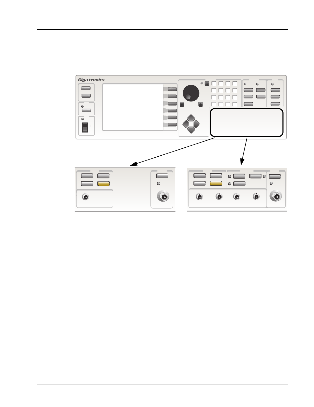
1.3.1 I/O Connectors (Front Panel)
Figure 1-1 illustrates the panel interface located on the front of the Series 12000A for all models. All
connectors are type BNC unless otherwise stated.
Introduction
STATUS
HELP
GPIB
REMOTE
LOCAL
LINE
STANDBY
STORE
RECALL
ALC INALC IN
GT12000A Microwave Synthesizer
0
SYSTEM
CONFIG
PRESET
Series 12400A Front Panel I/O
Figure 1-1: Series 12000A Front Panel Inputs/Outputs (All Models)
OUTPUT
ON/OFF
RF ON
RF OUT
STEP
CURSOR
STORE
RECALL
ALC INALC IN
DATA ENTRY
7
89
5
4
1
2
.
0
SYSTEM
CONFIG
PRESET
AM IN PULSE IN
nSec
GHz
dBm
m
Sec
MHz
6
dB
mSec
kHz
3
%
MANUAL
Sec
Hz
8K/-
MODULATION
AM
FM
FM/ M IN
f
Series 12500A/12700A Front Panel I/O
SWEEP LOCK
CW
SWEEP
MARKER
LIST
PULSE
POWERFREQUENCY
LEVEL
LEVEL
SWEEP
ALC
OUTPUT
ON/OFF
RF ON
RF OUT
Publication 31231, Rev. J, October 2003 1-5
Page 30
Series 12000A Microwave Synthesizers
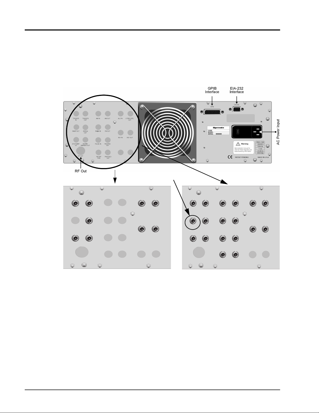
1.3.2 I/O Connectors (Rear Panel)
This section defines the panel interface and its functions located on the rear of the Series 12000A for all
models. Some connectors are duplicates of the front panel for all models (See Figure 1-1 for reference).
The RF Out Connector is installed on the front panel unless the instrument includes Option 22, which
relocates the connector to the rear panel (See Figure 1-2 below).
TRIGGER
IN
RAMP OUT
STOP SWP
I/O
AM IN
FM M INf
PULSE IN
PM EXT
TRIG
MARKER OUT
RF OUT
TRIGGER
OUT
.5V/GHz
OUT
BLANK/
Series 12400A Rear Panel I/O Connectors
Figure 1-2: Series 12000A Rear Panel Inputs/Outputs (All Models)
AM OUT
FM OUT
PM SYNC
OUT
PM VIDEO
OUT
(RAMP OUT for Only 127XXA)
LOCK/LEVEL
ALC IN
OUT
REF IN REF OUT
AM IN
FM M INf
PULSE IN
PM EXT
TRIG
AM OUT
FM OUT
PM SYNC
OUT
PM VIDEO
OUT
TRIGGER
IN
RAMP OUT
STOP SWP
I/O
MARKER OUT
RF OUT
TRIGGER
OUT
.5V/GHz
OUT
BLANK/
Series 12500A/12700A Rear Panel I/O Connectors
LOCK/LEVEL
ALC IN
OUT
REF IN REF OUT
1-6 Publication 31231, Rev. J, October 2003
Page 31

Table 1-2: Series 12000A I/O Connector Descriptions
Introduction
I/O
Connector
(Front)
N/A
RF OUT RF OUT
AM IN AM IN
N/A AM OUT
FM/fM IN FM/fM IN
N/A FM OUT
PULSE IN PULSE IN
I/O Connector
(Rear)
TRIGGER IN
TRIGGER OUT
RAMP OUT
.5V/GHz OUT
STOP SWP I/O
BLANK/MARKER
OUT
Description
Connector accepts a sweep or step trigger input ≥ 50
ns wide at TTL level to initiate a sweep or step.
Connector accepts a sweep trigger output coincedent
with the frequency step ending the event.
0 to +10 V ramp output, proportional to progress
between sweep limits (Signal directly proportional to
output frequency).
An output voltage directly proportional to the RF output
frequency.
TTL level signal, low input to stop frequency sweep or
output to indicate that a sweep has been stopped.
A sweep related output: +5 V or -5 V during band
changes, filter changes and Sweep retrace; 0 V during
sweep; +5 V or -5 V at marker frequencies (Signal
polarity is software controlled).
Instrument’s RF output on a type SMA (f) connector.
Option 22 - Moves the RF Output connector the rear
panel (See Appendix A for Option 22 details).
Option 23 - For Type N connector
Connector accepts the input signal from a 600 W
external amplitude modulation source See “Externally
Supplied AM Envelope” in Section 1.7.1.
An amplitude modulation waveform output at ~2 V
into 10 k.
(OPTION 24 AVAILABLE ON 125XXA/127XXA
ONLY)
Connector accepts the input signal from a 50 W
external frequency or phase modulation source. See
“Externally Supplied FM Envelope” in Section 1.7.3
and “External Supplied FM Envelope” in Sections
1.7.4 & 1.7.4.4.
A frequency modulation waveform output at ~2 V
into 10 k W.
(OPTION 24 AVAILABLE ON 125XXA/127XXA
ONLY)
PM input signal for external pulse modulation.
Connector accepts the input signal from a 50 W
external pulse modulation source. See “Externally
Generated PM Envelope” and “Externally Triggered
PM Envelope” in Sections 1.7.2 & 1.7.5.
P-P
P-P
124XXA
,
Model
125XXA/
127XXA
√ √
√ √
N/A
(127XXA
ONLY)
√ √
√ √
√ √
√ √
N/A √
N/A √
N/A √
N/A √
N/A √
√
Publication 31231, Rev. J, October 2003 1-7
Page 32

Series 12000A Microwave Synthesizers
Table 1-2: Series 12000A I/O Connector Descriptions (Continued)
I/O
Connector
I/O Connector
(Front)
PM SYNC OUT
N/A
ALC IN ALC IN
N/A
PM EXT TRIG
PM VIDEO OUT
LOCK/LEVEL
REF OUT
(Rear)
OUT
REF IN
Description
50 ns trigger pulse output at TTL levels (Approximately
4 V into 50 W), coincident with leading edge of the
pulse modulation envelope.
(OPTION 24 AVAILABLE ON 125XXA/127XXA
ONLY)
Connector accepts a pulse trigger input ≥ 50 ns wide
at TTL level to initiate an internally generated Singlet,
Doublet, Triplet or Quadlet pulse burst.
(OPTION 24 AVAILABLE ON 125XXA/127XXA
ONLY)
A pulse modulation envelope waveform at TTL level
(Approximately 4 V
PM only).
(OPTION 24 AVAILABLE ON 125XXA/127XXA
ONLY)
CURRENTLY NOT SUPPORTED
A TTL-compatible output (High indicates the output
frequency is phase locked and the output power is
leveled).
An external timebase input signal, 5 or 10 MHz ±1 ¥
-6
or better, 0.5 to 5 V
10
timebase. Input impedance is 100 W nominal.
A buffered square wave output at 10 MHz, 2 V
minimum into 50 W, derived from the internal or
external timebase.
into 50 W) (Internally triggered
P-P
, overrides the internal
P-P
P-P
Model
124XXA
N/A √
N/A √
N/A √
√ √
√ √
√ √
√ √
125XXA/
127XXA
1.3.3 Computer Interface
1.3.3.1 GPIB
The IEEE 488.2 interface connection (24-pin) between the Series 12000A and host computer
equipment for remote operation over the General Purpose Interface Bus (GPIB) is located on the rear of
the unit. The connector pin assignments are listed in Table 1-3 for all models.
Table 1-3: Series 12000A IEEE 488.2 Hardware Configurations
Pin Signal Pin Signal Pin Signal
1 D101 9 IFC 17 REN
2 D102 10 SRQ 18 GND (6)
3 D103 11 ATN 19 GND (7)
4 D104 12 Shield 20 GND (8)
5 EO1 13 D105 21 GND (9)
6 DAV 14 D106 22 GND (10)
7 NRFD 15 D107 23 GND (11)
8 NDAC 16 D108 24 GND Logic
1-8 Publication 31231, Rev. J, October 2003
Page 33

1.3.3.2 EIA-232
This 9-pin connector interfaces communications equipment using RS-232 format. See the table below
for the connector pin assignments to all models.
Table 1-4: EIA-232 Pin Assignments
Pin Function
1 Protective Ground
2 Transmitted Data
3 Received Data
4 Request To Send
5 Clear To Send
6 Data Set Ready
7 Signal Ground
8 Carrier Detect
9 Reserved for modem testing
Introduction
Publication 31231, Rev. J, October 2003 1-9
Page 34

Series 12000A Microwave Synthesizers
1.3.4 Power
All models of the Series 12000A contains primary and stand by power with interval switching. The
instrument automatically senses input line voltage in the range of 90 to 253 Vac, 47 to 64 Hz (400 Hz
Optional). There are no manual voltage adjustments or selection controls. The 12000A has a 3-Wire
power cord with a 3-terminal polarized plug for connection to the power source and safety ground. The
power cord cannot exceed 3 meters (9 feet) to meet safety requirements.
The safety ground is connected directly to the chassis. If a 3-to-2
wire adapter is to be used, be sure to connect the ground lead
from the adapter to earth ground. Failure to do this could cause
the instrument to float above ground, posing a shock hazard.
DO NOT position the equipment so that is difficult to operate the
disconnecting device (to remove the AC line cord).
WARNING
CAUTION
1.3.4.1 Line Fuse
All 12000A models have a line fuse container on the rear panel.
1.3.4.2 Fuse Installation
All models have a power line fuse that is 2A, Slo-Bo, 250V, Type T (See Figure 1-3 below for location)
The fuse holder is contained in the covered housing directly above the AC power connector on the rear
panel for all models. To gain access, use a small screwdriver or similar tool to snap open the cover.
Fuse Replacement
VOLTAGE
SELECTION
WHEEL
COVER
FUSE AND
FUSE HOLDER
1
1
0
1
2
0
AC POWER
INPUT
Figure 1-3: Fuse Holder
.
Pull out the small drawer on the right side of the housing (marked with an arrow) and remove the old
fuse. Replace with a new fuse, insert the drawer and close the housing cover, see figure above.
1-10 Publication 31231, Rev. J, October 2003
Page 35

1.4 Specifications
(Signal Parameters & Operational Modes)
Specifications
Introduction
Model
124XXA 125XXA/
127XXA
1.4.1 - CW Operation
1.4.2 - RF Output
1.4.3 - Spectral Purity
1.4.4 - Step Frequency Sweep
1.4.5 - Step Power Sweep
The following are specifications for the Series 12000A Microwave Synthesizers.
1.4.1 CW Operation
Ranges
10 MHz to 8 GHz
2 GHz to 8 GHz
10 MHz to 20 GHz
2 GHz to 20 GHz
Resolution
√√
√√
√√
√√
√√
Model
12408A 12508A 12708A
12428A 12528A 12728A
12420A 12520A 12720A
12422A 12522A 12722A
0.1 Hz (Standard)
Accuracy & Stability (Identical to Timebase Oscillator)
Timebase (Internal)
Aging Rate
Temperature Stability
Timebase (External)
Switching Time, List Mode
<500 ms to within 1 kHz of set frequency (Typical)
Switching Time, CW Mode
35 ms to within 1 kHz of set frequency (Includes IEEE overhead) (Typical)
10 MHz
<5 × 10
<±2 × 10
5 or 10 MHz (±1 x 10⁻⁶ or better) (Software selected)
0.5 to 5 V
-10
/day after 72 hours continuous oven operation
-10
/ °C (0 to +55°C)
into 100 W (Nominal)
P-P
Publication 31231, Rev. J, October 2003 1-11
Page 36

Series 12000A Microwave Synthesizers
Residual FM During Switching
Refer to FM Table, Wide Mode Residual Column, Section 1.7.3
Phase Offset Mode
Range
Resolution
Step Size
Accuracy
-180 to +180 degrees
.01 degrees, maximum
.01 to 180 degrees
Not specified. This is relative mode of operation and is designed to be used interactively
1-12 Publication 31231, Rev. J, October 2003
Page 37

1.4.2 RF Output
Maximum Leveled Output (0 to 35
Frequency Range (GHz) Output Power (dBm) Option 26 (dBm)
Incremental Level Range
-20 (Typical) to +25 dBm; -120 to +25 dBm (Option 26)
Resolution
-0.01 dB, entry and display
Introduction
C)
°
0.01 to 2 +15 dBm +14 dBm
>2 to <8 +15 dBm +15 dBm
8 to 15 +15 dBm +13 dBm
>15 to 20 +15 dBm +12 dBm
Minimum Calibrated Output Level
-120 dBm with attenuator Option 26
-10 dBm without attenuator Option 26
RF Off: Attenuates the output to <-140 dBm at the output connector
Flatness
±0.5 dB (-10 dBm to maximum specified power) at 25 ±10°C (Internally Leveled, CW or Frequency Step or Ramp Mode)
Add ±0.1dB/10 dB with attenuator option (±2.5 dB with Option 20*)
At 35 to 55°C, maximum output power is +13 dBm, flatness +/- 1 dB, Typical temperature coefficient is -0.025 dB per degree C
(*See Section 1.5.3 for Option 20 limitations involving use with the 124XXA)
Resolution
-Add 0.2 dB to Flatness (Internally Leveled, CW, Frequency Step or Ramp)
Maximum Slope of Level Variation
<0.5 dB/MHz
Output Switching Time
<500 ms; 20 ms with attenuator change
Output Impedance
50 W, nominal
Publication 31231, Rev. J, October 2003 1-13
Page 38

Series 12000A Microwave Synthesizers
Output SWR
<2.0:1 (Typical)
Level Drift
<0.05 dB/hour. Max 0.1 dB/24 hours
1-14 Publication 31231, Rev. J, October 2003
Page 39

1.4.3 Spectral Purity
Harmonics
Frequency (GHz) Harmonic (dBc) Power (dBm)
0.01 to 0.10 -30 +6
0.10 to 2 -50 +6
>2 to 20 -55 +6
Subharmonics
None, 0.01 - 2 GHz
0.01 - 2 GHz
55 dBc >2 GHz
A subharmonic is defined as any ¼, ½, or ¾ multiple of the fundamental RF Output
Nonharmonics
<-60 dBc from 0.01 to 16 GHz (offsets >300 Hz)
<-55 dBc from >16 to 20 GHz (offsets >300 Hz)
Introduction
Single-Sideband Phase Noise (
Freq. (GHz)
0.25 -101 -101 -109 -122 -129
0.5 -95 -95 -103 -122 -124
2 -87 -92 -94 -120 -125
4 -81 -86 -88 -110 -130
6 -81 -83 -83 -110 -130
8 -75 -80 -80 -105 -130
10 -75 -80 -80 -105 -125
18 -68 -73 -73 -97 -120
20 -68 -73 -73 -97 -120
Residual FM (Hz, rms, CW Mode)
Frequency Range
(GHz)
<2 GHz Decreases by ½ per oct Decreases by ½ per oct
2 to <4 <6 <45
4 to <8 <12 <70
8 to <16 <24 <160
16 to 20 <32 <280
dBc/Hz, CW mode, all power levels)
Offset from Carrier
100 Hz 1 kHz 10 kHz 100 kHz 1 MHz
Post Detection Bandwidth (Hz)
300 to 3000 50 to 15000
AM Noise
<-130 dB/Hz from 0.01 to 2 GHz
<-145 dBm/Hz at >2 GHz
Publication 31231, Rev. J, October 2003 1-15
Page 40

Series 12000A Microwave Synthesizers
1.4.4 Step Frequency Sweep
Range
FA (minimum frequency of instrument) to FB (maximum frequency of instrument)
Step Size
Any increment within the frequency resolution
Dwell Time
May be set in 1 µs increments from approximately 1µs to 200 sec
Setup Time
200 µs (Typical)
Accuracy & Stability
Same as in CW when locked at each step during dwell time
Modes
Start/Stop
Start/∆
CTR/∆
Start/Steps
Functions
Auto
Single
EXT
EXT Step
FA ≤ [F1 ≠ F2] ≤ FB
Sweeps up or down from a preset start frequency (F1) to a preset stop frequency (F2)
FA ≤ [F1 ± ∆F] ≤ FB
Sweeps up or down from a preset start frequency (F1) through a preset sweep width (∆F)
FA ≤ [CF ± (∆F/2)] ≤ FB
Sweeps up or down through a preset sweep width (∆F) centered symmetrically about a
preset center frequency (CF)
FA ≤ [F1 ± (Step Size × Number of Steps)] ≤ FB
Sweeps up or down from a preset start frequency (F1) through a preset number of frequency
steps
Continuous cycle of the preset sweep
A single cycle of the preset sweep or (with stop activated) a single preset step, initiated by
the manual operation of the front panel push-button or reception of the corresponding GPIB
command
A single cycle of the preset sweep initiated by each trigger from an external source
A single step of a preset step sweep initiated by each trigger input from an external source
1-16 Publication 31231, Rev. J, October 2003
Page 41

1.4.5 Step Power Sweep
Range
LA (minimum level of instrument) to LB (maximum level of instrument)
Step Size
Any increment within the instrument’s resolution
Dwell Time
May be set in 1 µs increments from approximately 1 µs to 200 sec
Setup Time
100 µs (Typical)
Accuracy & Stability
Same as in CW when locked at each step during dwell time
Introduction
Modes
Start/Stop
Start/∆
CTR/∆
Start/Steps
Functions
Auto
Single
EXT
EXT Step
LA £ [L1 ¼ L2] £ LB
Sweeps up or down from a preset start level (L1) to a preset stop level (L2)
LA £ [L1 ± DL] ≤ LB
Sweeps up or down from a preset start level (L1) through a preset sweep width (DL)
LA £ [CL ± (DL/2)] £ LB
Sweeps up or down through a preset sweep width (DL) centered symmetrically about a
preset center level (LF)
LA £ [L1 ± (Step Size ¥ Number of Steps)] £ LB
Sweeps up or down from a preset start level (L1) through a preset number of level steps
Continuous cycle of the preset sweep
A single cycle of the preset sweep or (with stop activated) a single preset step, initiated by
the manual operation of the front panel push-button or reception of the corresponding GPIB
command
A single cycle of the preset sweep initiated by each trigger from an external source
A single step of a preset step sweep initiated by each trigger input from an external source
Publication 31231, Rev. J, October 2003 1-17
Page 42

Series 12000A Microwave Synthesizers
1.5 Supplemental Specifications
Supplemental Specifications
124XXA
Model
125XXA/
127XXA
1.5.1 - General Specifications
1.5.2 - Weight & Dimensions
1.5.3 - Option 20 Specifications
1.5.1 General Specifications
Remote Interfaces
Operating Temperature
Environmental
Approvals
Power
Fuse Rating
1.5.2 Weight & Dimensions
Item Benchtop Model Packed for Air Shipment
√√
√√
√
GPIB IEEE STD 488.2 (GPIB), all parameters except AC power on/off
Serial EIA RS-232, Serial Interface, DB9 Connector
0 to 55°C
Complies with MIL-PRF-28800F, Class 3
CE marked
90-253 VAC, 47-64 Hz (400 Hz optional),150 Watts (Nominal)
2 A, SB
√
Width 16.75 in. (42.5 cm.) 24 in. (60.9 cm.)
Depth 21 in. 21 in.
Height 5.25 in. (13.3 cm.) 11.25 in. (28.6 cm.)
Volume 1850 cuin 1850 cuin
Weight 30 lbs. 40 lbs.
1-18 Publication 31231, Rev. J, October 2003
Page 43

1.5.3 Option 20 (High Power) Specifications
(Apply from 0× to 35×C)
Output Power
+20 dBm
Flatness
+/- 2.5 dB
Harmonics
<-5 dBc from 0.01 to 0.1 GHz
<-20 dBc for 0.1 to 20.0 GHz @ +20 dBm Output Power
Pulse On/Off (PULSE ON/OFF ONLY ON SERIES 12500A/12700A)
60 dBc
Introduction
AM (AM ONLY ON SERIES 12500A/12700A)
Functional, but not specified above 0 dBm
Option Activity
When the option is not active the output power is reduced by 2.0 dB
When active, the High Power Option switches in at +11 dBm
Publication 31231, Rev. J, October 2003 1-19
Page 44

Series 12000A Microwave Synthesizers
1.6 Specifications (Series 12500A/12700A)
(Signal Parameters & Operational Modes)
Specifications (Series 12500A/12700A)
1.6.1 - Ramp Frequency Sweep
1.6.2 - Ramp Power Sweep
Refer to Section 1.4 for specifications that apply to all models. Use this section for native specifications
to the Series 125XXA/127XXA models.
1.6.1 Ramp Frequency Sweep
A continuous sweep is generated within the instrument. The continuous sweep may be operated
simultaneously with digital power sweep.
Description
124XXA
N/A
N/A
Model
125XXA/
127XXA
√
(127XXA Only)
√
(127XXA Only)
Sweep Type Smooth frequency ramp progression sweep
Sweep Type Either up or down in frequency
Sweep Direction Either up or down in frequency
Sweep Ramp Shape Linear frequency ramp with respect to time
Sweep Range Linear frequency ramp with respect to time
Start Frequency Accuracy Phase locked to timebase (via YIG tune coil)
Stop Frequency Accuracy Phase locked to timebase (via YIG tune coil)
Halted Frequency Accuracy Phase locked to timebase (via YIG tune coil)
Start & Stop Freq. Resolution 0.1 Hz Standard (1 kHz, Option 36)
Minimum Sweep Width 100 Hz Standard (1 MHz, Option 36)
Maximum Step Width From the minimum frequency to the maximum. Frequency of the Series 12000A as configured
Sweep Width Resolution 0.1 Hz standard (1 kHz, Option 36)
Sweep Time 1 ms to 200 sec
Sweep Time Resolution 10 ms
Minimum Sweep Rate 100 kHz/sec
Maximum Sweep Rate 8 ms/octave
Sweep Linearity
Sweep Modulation Formats AM or Pulse Modulation
1-20 Publication 31231, Rev. J, October 2003
Better than 0.03% of sweep width relative to the 0 V to 10 V Ramp Output BNC voltage
(Swept time <100 sec) (Typical)
Page 45

O to 10 V Ramp Output
Vout = (10 V) |(fout - fstart)| / |(fstop - fstart)|(Frequency Ramp sweep mode)
Vout = (10 V) |(Pout - Pstart)| / |(Pstop - Pstart)|(Power Ramp sweep mode)
Vout = 0 to 10 V ramp @ current set sweep rate (Ramp during CW mode)
O.5 / GHz Output
Vout = (0.5 V) (Fout in GHz)
Sweep Modes
Introduction
Start/Stop
Start/∆
CTR/∆
∆ MKR
FA≤ [F1 = F2] ≤ FB
Sweeps up or down from a preset start frequency (F1) to a preset stop frequency (F2)
FA≤ [F1 ± ∆F] ≤ FB
Sweeps up or down from a preset start frequency (F1) through a preset sweep width (∆F)
FA≤ [CF ± (∆F/2)] ≤ FB
Sweeps up or down through a preset sweep width (∆F) centered symmetrically about a preset center
frequency (CF)
FA ≤ [Mx My]≠ ≤ FB
Sweeps up or down from a preset start frequency (Mx) through a preset marker (My)
Sweep Functions
Auto
Single
EXT
Continuous recycle of the preset sweep
A single cycle of the preset sweep initiated by manual operation of the front panel push-button or
reception of the corresponding GPIB command
A single cycle of reset sweep initiated by a trigger from an external source
Frequency Markers
(Twelve intensity, video and/or amplitude markers, individually selected from either the front panel or via the GPIB)
Resolution
Accuracy
Sweep width/4000
Same as Sweep linearity except the marker may vary ±25 mV relative to the linear 0 to +10 V RAMP
OUT
Amplitude Markers
Video Markers
Intensity Markers
A -10 to +10 dB change in RF output during analog frequency sweep
TTL level output or ±5 V
Provides a timed dwell of frequency sweep
Publication 31231, Rev. J, October 2003 1-21
Page 46

Series 12000A Microwave Synthesizers
1.6.2 Ramp Power Sweep
Continuous sweep, self generated within the instrument. Can be operated simultaneously with digital
frequency sweep.
Range
- 10 dBm to maximum power, up or down (-120 dBm is maximum power with Option 26)
Sweep Time (Any Sweep Mode)
2 ms to 200 sec in five ranges. Minimum sweep time is determined by the sweep width and the maximum sweep speed
Range Resolution
2 ms to 20 ms 10 ms
20 ms to 200 ms 100 ms
200 ms to 2 sec 1 ms
2 sec to 20 sec 10 ms
20 sec to 200 sec 100 ms
Minimum Sweep Width
.01 dB
Maximum Sweep Speed
1 dB/ms
Sweep Level Resolution (Any Sweep Mode)
0.01 dB
Start Level Accuracy (Any Sweep Mode)
0.2 dB to Flatness
Sweep Level Linearity (Any Sweep Mode)
±0.25 dB
Sweep Modes
Auto Continuous recycle of preset sweep
Single
EXT A single cycle of the preset sweep, initiated by a trigger input from an external source
A single cycle of the preset sweep, initiated by manual operation of the front panel push-button
or reception of the corresponding GPIB command
1-22 Publication 31231, Rev. J, October 2003
Page 47

1.7 Modulation Parameters & Operational Modes
Modulation Parameters & Operational Modes
124XXA
Introduction
Model
125XXA/
127XXA
1.7.1 - Amplitude Modulation (AM)
1.7.2 - Scan Modulation
1.7.3 - Frequency Modulation (FM)
1.7.4 - Phase Modulation (φM)
1.7.5 - Pulse/Square Wave Modulation (PM)
AM, FM, Pulse and Option 29 (Scan Modulation) driven by external waveforms is standard only on the
125XXA/127XXA models. Option 24 (Internal Modulation Generator) provides two function
generators for internally generated amplitude and frequency modulation envelope waveforms. A pulse
generator is also provided.
1.7.1 Amplitude Modulation (AM)
AM may be operated simultaneously with FM. AM Specifications apply with FM turned off.
1.7.1.1 AM Envelope Parameters
Modulation Depth
0 to 90% @ 0 dBm output power (Settable to 95.0%)
N/A √
N/A √
N/A √
N/A √
N/A √
Modulation Resolution
1%
Modulation Bandwidth
DC to 150 kHz, ±3 dB @ 0 dBm output
Modulation Accuracy
±10% of depth setting (e.g. A setting of 50% may be within a 40% to 60% reading)
Publication 31231, Rev. J, October 2003 1-23
Page 48

Series 12000A Microwave Synthesizers
1.7.1.2 Externally Supplied AM Envelope
Waveform
Any waveform compatible with bandwidth considerations
Scaling
0%/V to 95%/V
Input Voltage
Minimum: -1 V, Maximum: +1 V
Input Impedance
600 Ω (Nominal)
for 50% depth ±10% depth @ 1 kHz modulation rate
P-P
1.7.1.3 Internally Generated AM Envelope
See Option 24 specifications in Section 1.8.1
1.7.2 Scan Modulation
See Option 29 specifications in Section 1.8.2.
1-24 Publication 31231, Rev. J, October 2003
Page 49

1.7.3 Frequency Modulation (FM)
Specifications apply with Scan/AM and PM off. FM may be operated simultaneously with Linear AM
and or PM (PM & Linear AM not allowed simultaneously).
1.7.3.1 Wide Mode Envelope Parameters
Maximum Deviation
See table contained in Section 1.7.3.2
Minimum Deviation
10 kHz at 4 - 8 GHz (Other ranges proportionally)
Modulation Resolution
1 kHz (Deviation < 1 MHz); 10 kHz (Deviation < 1 MHz) (at 4 - 8 GHz, other range proportionally)
Flatness
Introduction
±2 dB for rates from 100 Hz to 1 MHz; ±3 dB to 8 MHz
Residual FM
See table contained in Section 1.7.3.2
Modulation Accuracy
±5% at max deviation, 190 kHz modulation rate
Distortion
<5% (±1 MHz Deviation)
Incidental AM
<±0.2%/MHz of Deviation
Publication 31231, Rev. J, October 2003 1-25
Page 50

Series 12000A Microwave Synthesizers
1.7.3.2 Narrow Mode Envelope Parameters
Maximum Deviation
See table below
Modulation Resolution
10 Hz (Deviation <10 kHz)
1 kHz (Deviation >10 kHz) (at 4 - 8 GHz, other ranges proportional)
Flatness
±2 dB for rates from DC to 1 MHz (measured at 1 V
±3 dB for 1 MHz to 8 MHz
input, i.e. 500 kHz Deviation)
P-P
Residual FM
Same as CW
Modulation Accuracy
±5% at max Deviation, 190 kHz modulation rate
Distortion
<±0.2%/MHz of Deviation
Incidental AM
<5% (±1 MHz deviation)
<1% @ 10 KHz (4 - 8 range)
Frequency (GHz) Max Wide Deviation (Pk) Max Narrow Deviation (Pk) Wide Mode Residual FM
.010 to .016 40 kHz 2 kHz <200 Hz
>.016 to .032 80 kHz 4 kHz <200 Hz
>.032 to .064 160 kHz 8 kHz <200 Hz
>.064 to .125 320 kHz 16 kHz <200 Hz
>.125 to .25 640 kHz 32 kHz <200 Hz
>.25 to .5 1.25 MHz 64 kHz <200 Hz
>.5 - 1 2.5 MHz 125 kHz <375 Hz
>1 - 2 5 MHz 250 kHz <750 Hz
>2 - 4 10 MHz .5 MHz <1.5 kHz
>4 - 8 20 MHz 1 MHz <3 kHz
>8 - 16 40 MHz 2 MHz <6 kHz
>16 - 20 80 MHz 4 MHz <12 kHz
1-26 Publication 31231, Rev. J, October 2003
Page 51

1.7.3.3 Internally Generated FM Envelope
See Option 24 specifications in Section 1.8.1
1.7.3.4 Externally Supplied FM Envelope
Waveform
Any waveform compatible with bandwidth considerations
Rate
DC to 8 MHz
Input Sensitivity, Settable
1 V
for maximum Peak deviation (FM deviation control set to maximum)
P-P
Input Impedance
Introduction
50 W (Nominal)
Publication 31231, Rev. J, October 2003 1-27
Page 52

Series 12000A Microwave Synthesizers
1.7.4 Phase Modulation (φM)
Specifications apply with SCAN/AM and PM off. fM may be operated simultaneously with Linear AM
and or PM (PM & Linear AM not allowed simultaneously).
1.7.4.1 Wide Mode Envelope Parameter
Maximum Deviation
See table contained in Section 1.7.4.2
Maximum Resolution
10 kHz at 4 - 8 GHz (other ranges proportional)
Modulation Resolution
.01 radians (at 4 - 8 GHz, other ranges proportional)
Flatness
±2 dB for rates from 100 Hz to 100 kHz
Modulation Accuracy
±5% (relative to FM) at max. deviation, 100 kHz modulation rate
Distortion
<5% ( ±1 MHz deviation)
Incidental AM
<±0.2%/MHz of deviation
1.7.4.2 Narrow Mode Envelope Parameters
Maximum Deviation
See table is on next page
Modulation Resolution
.01 radians (at 4 - 8 GHz, other ranges proportional)
Flatness
±2 dB for rates from 100 Hz to 1 MHz 9 (measured at 1 V
1-28 Publication 31231, Rev. J, October 2003
input, i.e. 500 kHz Deviation)
P-P
Page 53

Modulation Accuracy
±5% (relative to FM) at max deviation, 100 kHz modulation rate
Distortion
<5% (±1 MHz deviation)
Incidental AM
<±0.2%/MHz of deviation
Frequency (GHz) Max Wide Deviation Max Narrow Deviation
.010 to .016 .40 radians .02 radians
>.016 to .032 .80 radians .04 radians
>.032 to .064 1.6 radians .08 radians
>.064 to .125 3.2 radians .16 radians
>.125 to .25 6.4 radians .32 radians
> .25 to .5 12.5 radians .64 radians
>.5 to 1 25 radians 1.25 radians
>1 to 2 50 radians 2.5 radians
>2 to 4 100 radians 5 radians
>4 to 8 200 radians 10 radians
>8 to 16 400 radians 20 radians
>16 to 20 800 radians 40 radians
Introduction
1.7.4.3 Internally Generated PM Envelope
See Option 24 specifications in Section 1.8.1
1.7.4.4 External Supplied FM Envelope
Waveform
Any waveform compatible with bandwidth considerations
Rate
10 Hz to 100 kHz
Input Sensitivity, Settable
1 V
for maximum peak deviation (FM deviation control set to Maximum)
P-P
Input Impedance
50 W (Nominal)
Publication 31231, Rev. J, October 2003 1-29
Page 54

Series 12000A Microwave Synthesizers
1.7.5 Pulse/Square Wave Modulation (PM)
Specifications apply with Scan/AM and FM off. PM may be operated with FM.
1.7.5.1 PM Basic Operation
On/Off Ratio
> 80 MHz
Rise Fall/Times:
Rise Time Frequency Range
<10 ns >500 MHz
<50 ns 64 to 500 MHz
<350 ns 25 to 64 MHz
<500 ns <25 MHz
Overshoot, Undershoot & Ringing
<10%, >500 MHz
Settling Time (to within 1 dB)
< 75 ns (for pulse width > 75 ns)
Level Pulsed Output Accuracy (Reference to CW Output Power) at 25 ± 10
±0.5 dB, ≥100 ns pulse width (±1 dB pulse width, between 100 ns and 75 ns, Typical). (Requires a typical setup time of 100 ms after
initial setting)
° C
Typical Settling Time for a Series of Leveled Pulses
100 ms
Demand Pulse Polarity
RF will be on with TTL level demand pulse at Pulse Modulation
Input BNC either at high or low logic level, selectable
Time Between Start of Demand Pulse (Video In) & Start of RF Pulse
< 50 ns
Minimum Required RF OFF Time between Pulses
100 ns
1-30 Publication 31231, Rev. J, October 2003
Page 55

Delivered Minimum Pulse Widths
Minimum Width Frequency Range
20 ns >500 MHz
100 ns 64 to 500 MHz
1 ms <64 MHz
1.7.5.2 Internally Generated PM Envelope
See Option 24 specifications in Section 1.8.1
1.7.5.3 Externally Generated PM Envelope
(One Envelope produced by each pulse)
Repetition Rate
5 Hz to 5 MHz, leveled
DC to 10 MHz, unleveled
Introduction
Pulse Offset Delay (Output Envelope Leading Edge referenced to Input Pulse Leading Edge)
50 ns, typical
Input Pulse Required
Positive or negative-going TTL voltage Level trigger pulse, ≥75 ns wide (leveled output)
≥ 20 ns wide (unleveled output). Pulse must be able to drive a 50 ohm load
Pulse Width
Defined by external pulse width
Publication 31231, Rev. J, October 2003 1-31
Page 56

Series 12000A Microwave Synthesizers
1.8 Supplemental Specifications (Series 12500A/12700A)
Model
Supplemental Specifications (Series 12500A/12700A)
124XXA
125XXA/
127XXA
1.8.1 - Option 24 Specifications
1.8.2 - Option 29 Specifications
N/A √
N/A √
1.8.1 Option 24 (Internal Modulation Generator) Specifications
1.8.1.1 Amplitude Modulation Source
Waveform
Sine, square, triangle, ramp (+ or -), Gaussian Noise
Rate
0.01 Hz to 1 MHz, all waveforms
Resolution
0.01 Hz
Accuracy
±0.01 Hz ± Timebase Accuracy
THD
1 % (Typical)
AM Output
2 V
, into 1 M W
P-P
1-32 Publication 31231, Rev. J, October 2003
Page 57

1.8.1.2 Frequency Modulation Source
Waveform
Sine, square, triangle, ramp (+ or -)
Rate
0.01 Hz to 1 MHz, all waveforms
Resolution
0.01 Hz
Accuracy
±0.01 Hz ± Timebase Accuracy
THD
1 % (Typical)
Introduction
FM Output
2 V
, into 1 M W
P-P
1.8.1.3 Pulse Modulation Source
Rate
1 Hz to 3 MHz
Rate Resolution
Range Resolution
1 Hz to 1 kHz 1 Hz
1 kHz to 10 kHz 10 Hz
10 kHz to 100 kHz 100 Hz
100 kHz to 1 MHz 1 kHz
1 MHz to 3 MHz 10 kHz
±2.5% of range maximum value; fm <100 KHz
Accuracy
Jitter Same as instrument timebase
±4% of range maximum value; f
±10% of range maximum value; f
100 KHz to <1 MHz
m
>1 MHz
m
Publication 31231, Rev. J, October 2003 1-33
Page 58

Series 12000A Microwave Synthesizers
1.8.1.4 Pulse Start Variable Delay
(Referenced to Sync Output)
Range
0 to 1.67 seconds
Resolution
10 ns
Accuracy
±2.5% of setting or ±20 ns, whichever is greater
Jitter
±0.01% of setting or ±100 ps, whichever is greater
1.8.1.5 Pulse Width
Range
0 to 1.67 seconds
Resolution
10 ns
Accuracy
±2.5% of setting or ±20 ns, whichever is greater
Jitter
±0.01% of setting or ±100 ps, whichever is greater
1-34 Publication 31231, Rev. J, October 2003
Page 59

1.8.1.6 Pulse Modes
(Triggered, Gated, Delayed, Singlet, Doublet, Triplet, or Quadlet and Free Running)
Interval
Range 100 ns to 1.67 seconds
Resolution 10 ns
Accuracy ±2.5% of setting or 20 ns, whichever is greater
Jitter 0.01% of setting or 100 ps, whichever is greater
Introduction
NOTE:
*
and quadlets are the same. The start delay for pulse one is independent.
The interval between pulse one and pulse two, and the interval between triplets
1.8.1.7 Externally Triggered PM Envelope
(One PM envelope produced by each trigger)
Repetition Rate
5 Hz to 5 MHz
Pulse Delay
Set by internal delay control
Pulse Width
Set by internal width control
Input Trigger Required
Positive or negative-going TTL Level trigger pulse, >20 ns wide, unleveled or >75 ns wide, leveled
1.8.1.8 PM Sync Output
TTL levels into a 50 W load, 50 ns pulse coincident with start delay
1.8.1.9 PM Video Output
TTL levels into a 50 W load
Publication 31231, Rev. J, October 2003 1-35
Page 60

Series 12000A Microwave Synthesizers
1.8.2 Option 29 (Scan Modulation) Specifications
Specifications apply with FM and PM turned off.
1.8.2.1 Envelope Parameters
Frequency of Operation
0.01 to 20 GHz
1.8.2.2 Scan Mode
Range
0 to 60 dB, ≥ +10 dBm (Settable to 65 dB)
Resolution
0.1 dB
Scaling
0 dB/V to 65 dB/V
Input Voltage
Minimum: 0 V, Maximum: +6 V
Step Response
<1 microsecond for 50 dB change; <10 ms, <1 GHz
Frequency Response
DC to 150 kHz, sine wave
Input Impedance
600 W (Nominal)
Accuracy (At cal points)
±0.25 dB plus +/- 5% of depth in dB (For .01 to 2 GHz, specification applies
only up to 30 dB) and frequencies above 2 GHz is 50 dB.
Linearity at ±0.6 dB (0 - 20 dB), ±1 dB (20 - 50 dB)
1-36 Publication 31231, Rev. J, October 2003
Page 61

1.8.2.3 Internally Generated Scan/AM Envelope
See Specifications for Option 24 in section 1.8.1
1.8.2.4 Power
2 dB reduction in power, .01-20 GHz
Introduction
Publication 31231, Rev. J, October 2003 1-37
Page 62

Series 12000A Microwave Synthesizers
1-38 Publication 31231, Rev. J, October 2003
Page 63

2.1 Introduction
2
Front Panel Operation
Model
Introduction (Front Panel Operation)
This chapter describes how to operate the Series 12000A Microwave Synthesizer from its front panel.
Use the list below for reference. Sectional header page references are only provided for items pertaining
directly to application examples.
• Chapter 1 - Instructions on how to install and interface the instrument before operating it for the first
time for all three models
• Chapter 3 - Instructions on how to operate the instrument from a remote host computer over the
General Purpose Interface Bus (GPIB) or an RS-232 serial connection
This chapter contains the following major sections:
• Front Panel Description
• Front Panel Applications
2.2 Front Panel Description
Frontal Panel Description
124XXA
√ √
Model
124XXA
125XXA/
127XXA
125XXA/
127XXA
2.2.1 - Series 12000A Front Panel Layout Descriptions
The Series 12000A front panel contains the controls and display for complete local operation of the
instrument. Front panel controls are grouped according to functions performed. Descriptions of the
controls are referenced to the blocked numbers illustrated in Figure 2-1 on the next page for all models.
Publication 31231, Rev. J, October 2003 2-1
√ √
Page 64

Series 12000A Microwave Synthesizers
Figure 2-1: Series 12000A Front Panel Layouts
2-2 Publication 31231, Rev. J, October 2003
Page 65

2.2.1 Series 12000A Front Panel Layout Descriptions
Front Panel Operation
1
2
3
4
Power
When this power switch is turned ON, the adjacent LED will be green. When the power switch is OFF
but main power is connected on the rear panel, the LED will be yellow to indicate a standby condition.
When the LED is OFF, the main power is disconnected (line cord) or otherwise not supplying ac power.
Help
Press [HELP] at any time to display the help screen for the selected option or the process being
performed when the Help switch is pressed. Press the [HELP] switch again or press [Exit Help] from the
menu to exit the Help screen.
Local
Press [LOCAL] to transfer operation of the instrument to Local. When in the Remote mode, all front
panel controls except the Local switch will be disabled to prevent unauthorized or accidental changes
being made at the instrument. The LED indicator adjacent to the Local switch will be ON when the
Remote mode is selected; it will be OFF in the Local mode.
Status
Press [STATUS] to display the current operating mode, frequency, and level. Press [STATUS] again to
return to the previous menu, or press any function key to go directly to that function.
5
Display
The display is a 3" x 4" liquid crystal display (LCD) with 320 x 240 line resolution, 0.30 mm dot pitch,
and a cold-cathode fluorescent lamp (CCFL) backlight for optimum viewing. The contrast of the display
is software controlled (See
the cursor keys, then select knob to adjust to desired contrast). The last contrast value set is saved and
restored upon bootup or reinitialization.
The Display field includes six interactive softkeys to select the respective options displayed on the right
side of the screen (See Figure 2-1 under item 5 for the six buttons to the right of the screen). The options
will change according to the menu being displayed. The screen displays real-time configuration and
operating data. Front panel configuration parameters are automatically saved in non-volatile memory
when entered.
System Field
on page 2-6 under item layout number 9. Select contrast from
Figure 2-2: Display Screen with Interactive Softkeys
Publication 31231, Rev. J, October 2003 2-3
Page 66

Series 12000A Microwave Synthesizers
Data Entry Field
6
The DATA ENTRY field contains the 12-button keypad, Units keys, Knob Lock key, CURSOR keys,
and the resolution STEP Up/Down keys and adjusting knob. Figure 2-3 illustrates the Data Entry field.
Each control within the field is explained in the following paragraphs.
Adjusting
Knob
Step Down
Key
Step Up
Key
STEP
CURSOR
Knob Lock
Key
DATA ENTRY
12-Button
Keypad
7
4
1
0
Cursor Keys
89
5
2
.
BK/-
Units
Keys
nSec
GHz
dBm
mSec
MHz
6
dB
mSec
kHz
3
%
Hz
Sec
Figure 2-3: Data Entry Field (All Models)
Data Entry Keypad
Use this 12-button numeric keypad to enter parameter values and other data that require specific
values. The BK/ - key (Located below the numeric 3 key) has a dual function. If it is pressed before
a numeric key, a minus sign will precede the first digit. If it is pressed after one or more numeric
keys, it functions as a backspace to delete the previous entry.
Unit Keys
Press the appropriate Units key to select the units of the parameter in the display and finishes the
numeric entry. Any Units key can be used to complete numeric entries without units.
Knob Lock Key
Press this key to lock (disable) the adjusting knob to prevent unauthorized or accidental changes.
Press the key again to unlock the knob. The adjacent green LED will be ON when the adjusting
knob is disabled, and OFF when the knob is enabled.
Adjusting Knob
This knob increments or decrements a parameter value by the selected resolution. See Section
2.3.2.3 for instructions to set the resolution.
2-4 Publication 31231, Rev. J, October 2003
Page 67

Front Panel Operation
Step Keys
These keys increment or decrement a parameter value by one each time they are pressed. The keys
duplicate the action of the adjusting knob except that they always step the value up or down by
one. See Section 2.3.2.3 for instructions to set the resolution.
Cursor Keys
These four cursor directional keys, arranged in a diamond pattern, step the display cursor up, down,
left and right. The cursor is the highlighted data in the display.
Frequency Field
7
This field controls the parameters for frequency and sweep operation. Also accesses List mode.
CW
Press [CW] to display the current frequency and to enable frequency changes. Use the numeric
keypad to change the frequency, and the adjusting knob and/or step keys to adjust the frequency in
selective steps.
Sweep
Press [SWEEP] to configure a frequency sweep and to select alternate sweep methods. The sweep
parameters can be changed while this menu is displayed. In this mode the LEVEL and LOCK
LEDs are not updated.
RAMP SWEEP IS ONLY AVAILABLE ON THE SERIES 127XXA.
List
Press [MARKER] to display the 12 frequency markers used in frequency sweep operation. See
Section 2.3.4 for operation.
Marker
Press [CW] to display the current frequency and to enable frequency changes. Use the numeric
keypad to change the frequency, and the adjusting knob and/or step keys to adjust the frequency in
selective steps.
Manual
CURRENTLY NOT SUPPORTED.
Publication 31231, Rev. J, October 2003 2-5
Page 68

Series 12000A Microwave Synthesizers
Power Field
8
This field controls the parameters for power level and sweep operation.
Level
Press [LEVEL] to adjust the output signal level.
Sweep
Press [SWEEP] to configure a power sweep and to select alternate sweep methods. The sweep
parameters can be changed while this menu is displayed. In this mode the LEVEL and LOCK
LEDs are not updated.
RAMP SWEEP IS ONLY AVAILABLE ON THE SERIES 127XXA.
ALC
The resulting menu when pressing [ALC] controls the Automatic Level Control (ALC) functions.
In addition to selecting the mode and sensor for leveling, the step attenuator, if fitted, can be set to
a fixed value.
CURRENTLY THE ALC INPUT IS NOT SUPPORTED.
System Field
9
The SYSTEM field provides the means to configure the operating parameters and to set the IEEE 488
address. It also provides Store and Recall of up to 10 instrument setup configurations, and a list of
configured (preset) items.
Store
Press [STORE] to store the current instrument setup. At the prompt, enter an address of 0 through
9, with current assignments and free addresses displayed. Press the number 2 data entry key and the
current setup is stored in address 2.
Recall
Press [RECALL] to recall a stored instrument setup. The address of each stored configuration will
be displayed.
Config
Press [CONFIG] to display the instrument configuration. To change the configuration data to
generate a new setup, and then store that data to any available memory address for recall when
needed.
Preset
Press [PRESET] to display the preset menu. Pressing Initialize NVRAM, sets NVRAM to default
values (clears lists, level corrections and setups) and presets the instrument to the factory settings.
See Section 2.3.23 for information on Preset.
2-6 Publication 31231, Rev. J, October 2003
Page 69

Front Panel Operation
Figure 2-4: System Configuration Selection (Preset)
10
Modulation Field
The MODULATION field selects the type of modulation to be used. AM, FM, φM and PM are available
(SERIES 125XXA/127XXA ONLY).
AM
Press [AM] to select amplitude modulation. AM can be linear, expressed in percent, or Scan
(Option 29), expressed in dB with the output power being proportional to the input voltage. AM
can be internal or from an external source (Internal AM is available only when Option 24 is
installed).
Scan
To activate Scan modulation toggle the AM mode from linear to Scan.
FM
Press [FM] to select frequency modulation. FM can have a narrow bandwidth of dc to 1 MHz and a
maximum deviation of 1 MHz (in the 4 to 8 GHz range), or FM can have a bandwidth of 100 Hz to
8 MHz and a maximum deviation of 20 MHz (in the 4 to 8 GHz range). FM can be internal or from
an external source (Internal FM is available only when Option 24 is installed).
fM
First press [FM] then use the mode parameter to select phase modulation.
PM
Press [PM] to select pulse modulation. PM can be internal or from an external source (Internal PM
is available only when Option 24 is installed).
11
Input Field
The INPUT field contains four BNC connectors. External modulation sources can be applied to the AM,
FM and PM connectors (φM uses the FM connector) (CURRENTLY THE ALC INPUT IS NOT
ACTIVE. SERIES 124XXA CONTAINS ONLY THE ALC BNC).
Publication 31231, Rev. J, October 2003 2-7
Page 70

Series 12000A Microwave Synthesizers
12
RF Field
The RF field provides an RF connector and a switch to turn the output on and off. The adjacent LED will
be ON when the RF output is turned on. The front panel RF connector will be relocated to the rear
panel when Option 22 is installed.
A blinking RF ON LED indicates that RF is set to ON but there is currently no RF out. This indicates
that the unit has “RF Retrace” set to “RF Off” (Default) and is in triggered moved and is not being
currently triggered. If “RF Retrace” is set to “RF On”, the power would remain on after trigger ceases and
the “RF ON” indicator will remain steadily on.
2-8 Publication 31231, Rev. J, October 2003
Page 71

2.3 Front Panel Applications
Front Panel Applications
Front Panel Operation
Model
124XXA
125XXA/
127XXA
Page
2.3.1 - Direct Entry
2.3.2 - Set a CW Signal
2.3.3 - Step Frequency Sweep Configuration
2.3.4 - Add Markers to a Frequency Sweep
2.3.5 - List Set Up
2.3.6 - List Entry Speed Up
2.3.7 - List Execution Speed Up
2.3.8 - List Points Storage
2.3.9 - Step Power Sweep Configuration
2.3.10 - ALC Operation
2.3.11 - Ramp Frequency Sweep Configuration N/A
2.3.12 - Ramp Power Sweep Configuration N/A
2.3.13 - External Amplitude Modulation (AM) N/A
√ √
√ √
√ √
√ √
√ √
√ √
√ √
√ √
√ √
√ √
√
(127XXA Only)
√
(127XXA Only)
√
2-11
2-12
2-15
2-17
2-19
2-23
2-23
2-25
2-27
2-29
2-32
2-34
2-36
2.3.14 - Internal Amplitude Modulation (AM) N/A
2.3.15 - External Scan Amplitude Modulation N/A
2.3.16 - Internal Modulation (Opt. 24) with Scan AM (Opt. 29) Selected N/A
2.3.17 - External Frequency Modulation (FM) N/A
2.3.18 - Internal Frequency Modulation (FM) N/A
2.3.19 - Phase Modulation (fM) N/A
2.3.20 - External Pulse Modulation (PM) N/A
2.3.21 - Internal Pulse Modulation (PM) N/A
2.3.22 - Interface Configuration
2.3.23 - System Reset
The remainder of this chapter presents applications examples to illustrate how to operate the 12000A
by using the controls on the front panel. Refer to Chapter 3 in this publication if the 12000A will
operate over a remote interface through the General Purpose Interface Bus (GPIB) or the RS-232 serial
interface.
√ √
√ √
√
√
√
√
√
√
√
√
2-37
2-39
2-41
2-42
2-44
2-46
2-47
2-48
2-50
2-52
Publication 31231, Rev. J, October 2003 2-9
Page 72

Series 12000A Microwave Synthesizers
The 12000A features a comprehensive HELP system linked to the current display. Press the
key to display general information about the function — this screen also provides softkeys selections for
more detailed help topics.
[HELP]
2-10 Publication 31231, Rev. J, October 2003
Page 73

2.3.1 Direct Entry
Data Entry for the various menus depends on the type of entry. Parameters with numeric values can be
entered and changed by the following methods:
2.3.1.1 Numeric Keypad Entry
With the cursor positioned at the far left (e.g., on FREQ in the Fixed Frequency menu as shown in
Figure 2-5), enter the numeric value with the keypad. The entry will display in the bottom part of the
menu, and will be transferred to the
appropriate Units key (any Units key completes an entry that does not require units).
Frequency
Front Panel Operation
line when the entry is completed by pressing the
To enter a negative number, press the
digit has been entered, this key functions as a backspace to delete the previous digit.
2.3.1.2 Increment/Decrement
With the cursor positioned at the far left of the menu, use the knob or step button to continuously vary
the numeric value of the digits on the same line with the cursor. The resolution of the steps can be
changed by pressing the
[Step Size]
2.3.1.3 Individual Digit Changes
With the cursor positioned at the far left, use the horizontal (left/right) cursor keys to highlight the digit
to be changed, then use the knob or step buttons to change the value as desired. Move the cursor to the
second digit to be changed and repeat the process until all digits are changed as desired. Parameters with
selective values are changed by scrolling through the selections using the knob or step buttons.
Figure 2-5 is an illustration of the 12000A Fixed Frequency menu with the interactive softkeys. Press the
softkey to perform the function shown in the adjacent block in the menu. The highlighted area in the
display is the cursor, controlled by the cursor keys
[BK/-] keypad button before entering the first digit. After the first
softkey.
Publication 31231, Rev. J, October 2003 2-11
Page 74

Series 12000A Microwave Synthesizers
2.3.2 Set a CW Signal
Press [CW] or [LEVEL] to generate a fixed frequency at a fixed amplitude. Pressing [CW] will select the
Frequency field and pressing
used to one field or the other in either menu. The menu illustrated in Figure 2-5 will display, showing
the current or last-used frequency.
[LEVEL] will select the Power Level field. The up and down cursor can be
Figure 2-5: Fixed Frequency Menu with Softkeys
With the cursor at the far left highlighting the field name as in Figure 2-5, use the keypad to enter the
frequency. The value entered will display at the bottom of the screen. When all digits are entered, press
the appropriate [UNITS] key to transfer the value to the Frequency line.
In place of using the keypad, the frequency or power digits can be changed by moving the left or right
cursor to the digit to be changed and then making the change with the knob or Step keys. Move the
cursor to any additional digits to be changed and repeat the process. To change the incremental
resolution of the knob or the step keys, press
resolution or
keypad.
[Step /10]
to decrease the resolution. In addition, the step size can be entered with the
2.3.2.1 Transfer To/From a Marker
The CW frequency can be added to the list of Markers or any Marker value can be transferred to the
CW frequency. To transfer the CW frequency to the list of Markers, for first marker, press
[Frequency→Mrkr]
the frequency will be assigned, then press
frequency and use it as the CW frequency, press
number of the Marker to be transferred to the CW frequency, then press
transfer.
, for second marker press
[Step Size]
[Select Marker]
[Copy Freq]
[Marker→Freq]
and select either
to select the Marker number to which
to complete the transfer. To retrieve a marker
, press
[Step x10]
[Select Marker]
[Copy Mrkr]
to increase the
to complete the
and select the
2-12 Publication 31231, Rev. J, October 2003
Page 75

2.3.2.2 Change Output Phase
The Phase Change menu is accessed via a softkey from the CW menu.
Front Panel Operation
Figure 2-6: Phase Adjustment Selection
Figure 2-7: Phase Adjustment Selection (Phase Change)
• The minimum and maximum values allowed are +/- 180.00 degrees
• The maximum step size is +180.00 degrees and the minimum is +0.01 degrees
The output phase is NOT changed until the
Φ
The “Change
by:” value can be set, reset, or dialed in with the knob with NO change in output phase.
The phase will change by the amount selected each time the “
” twice when “Change Φ
pressing “
SET
“SET”
softkey is pressed.
SET
” softkey is pressed. For example,
by:” is set to +90 degrees will shift your output phase by +180
degrees.
CWFreq > 4 GHz
For frequencies equal to and above 4 GHz, the output phase will shift at once with no delays.
CWFreq < 4 GHz
For frequencies below 4 GHz, the phase shift will be applied many times, with a delay, to account for frequency division in lower bands.
Also, the phase shift will be broken down into increments of ten degrees, sent multiple times with delays, at frequencies under 4 GHz.
This introduces some additional error not seen from 4 GHz and up. The typical worst case time to complete the phase shift is
1.7 s (11 MHz with 179 degrees shift). See table below for other typical times.
Publication 31231, Rev. J, October 2003 2-13
Page 76

Series 12000A Microwave Synthesizers
Table 2-1: Phase Shift Completion Times
Typical Time for Completion of Phase Shift
CWFreq
11 MHz 11 MHz 50 MHz 500 MHz 1 GHz 2 GHz 2 GHz 4 GHz 4 GHz 8 GHz 16 GHz
Φ Shift
Timing
☛
☛
179 º 10 º 179 º 179 º 179 º 179 º 10 º 179 º 10 º 179 º 10 º
1.7 s 190 ms 420 ms 26 ms 14 ms 7 ms 680
NOTE:
is typically less than a few percent. Below 4 GHz, due to the need to send multiple
phase changes, the potential error increases.
NOTE:
frequency to drift over time.
The phase shift increment is an approximate number. Above 4 GHz, the error
Using this feature disables frequency-dithering. This will cause the output
2.3.2.3 Change Resolution
Currently resolution is available in the Step Size menu, but there has been no “Maximum” setting. The
menu is now accessible at the top level in the CW menu. The Resolution softkey was added to the
bottom of the CW softkey menu. “Maximum Resolution” was added and “Natural Resolution” was
renamed “Floating Resolution” (The mode that displays only significant digits).
375
m
375
m
375
m
375
m
m
2-14 Publication 31231, Rev. J, October 2003
Page 77

2.3.3 Step Frequency Sweep Configuration
Use this feature to set up a step frequency sweep. Figure 2-8 illustrates the Step Frequency Sweep menu.
A Step Frequency Sweep will start and stop at the frequency values designated in the configuration. The
dwell time and the output power at each step also need to be defined. The Repeat mode defines when
the sweep starts and the appropriate trigger needs to be defined.
Use the up and down cursor keys to move from field to field in the menu. Use the step keys or the knob
to toggle between options in each field. For numeric values the numeric keypad can be used also as
described in Section .
Front Panel Operation
Figure 2-8: Step Frequency Sweep Menu
1. Move the cursor to highlight the specific parameter to be configured, then look at the options for
that parameter by pressing the up or down Step key. Additional options can be selected with the
softkeys to:
a. Set up an alternate Step Frequency sweep with individual parameters as defined
in this section.
b. Set up the Step parameters.
2. Press
3. Press
4. Press
5. Press
[Alt Sweep]
having to reconfigure each time.
[Dual Sweep]
[Step Perams]
Points/Dwell or Point/Sweep time.
[Trigger Sweep]
to configure a second Step or Ramp sweep that can be run alternately without
to configure a dual Frequency-Power sweep.
to see the options for selecting the Step/Dwell or Step/Sweep time or the
to start a Power sweep after the sweep has been configured.
Publication 31231, Rev. J, October 2003 2-15
Page 78

Series 12000A Microwave Synthesizers
2.3.3.1 Step Frequency Sweep Parameters
Sweep Type
The sweep type is selective between Step and Ramp (Ramp is only available on Series 127XXA models).
This section details how to set up a Step Frequency sweep; See Section 2.3.11 for instructions on how to set
up a Ramp Frequency sweep. With the cursor on Sweep Type, press either Step key to select Step.
Parameters
The options are Start/Stop and Center/Span. Use Start/Stop to run a sweep with specific start and stop
frequencies. Select Center/Span to set up a sweep that allows entering the start frequency and the total width
of the sweep. The instrument computer then determines the upper and lower sweep limits. The sweep will run
between the upper and lower values of a frequency range.
Start or Center Frequency
When using the Start/Stop option, enter the start frequency. When using the Center/Span option, this entry will
change to Center Frequency. Enter the center frequency of the sweep.
Stop Frequency or Frequency Span
When using the Start/Stop option, enter the stop frequency. When using the Center/Span option, this entry will
change to Frequency Span. Enter the total frequency that the sweep will span across.
Frequency Step
Enter the value for each step of the sweep.
Dwell Time
Enter the time the sweep will dwell at each step. The dwell time does not include the transition time to arrive at
the dwell point.
Power Level
Set the power output level in this menu in the same manner as described in Section 2.3.2.
Repeat Mode
This option determines how a sweep will run. The choices are Single Step, Single Sweep, or Continuous.
RF LED Blink Mode
A blinking RF ON LED indicates that RF is set to ON but there is currently no RF out. This
indicates that the unit has “RF Retrace” set to “RF Off” (Default).
Trigger Type
Select the type of trigger that will be used to initiate the frequency sweep. The options are Immediate, which
means that a sweep will run immediately when selected; Softkey or GPIB, which will trigger a sweep when
either the softkey is pressed or a command is received over the GPIB; and Trigger In BNC, which will trigger a
sweep when a signal is applied to the Trigger In BNC from an external source.
☛
NOTE:
The Immediate mode is not valid for single step and single sweep.
2-16 Publication 31231, Rev. J, October 2003
Page 79

2.3.4 Add Markers to a Frequency Sweep
Markers can be added to a sweep in different ways to identify their position in the sweep. Markers can be
entered as video, intensity, or amplitude. Video markers illuminate the vertical reticule when the
markers are reached. Intensity markers cause the intensity of the sweep to increase when the markers are
reached. Amplitude markers generate a blip (Positive or negative) when the markers are reached.
Front Panel Operation
☛
To set the markers and their parameters, press
Figure 2-9. In this menu illustration, the first two markers have been set at 10.0 and 10.5 GHz, and as
Amplitude types, all indicated by the solid white tiles. The cursor is sitting on marker 3.
To set a marker from the Edit Markers menu:
NOTE:
Leave the menu to activate the markers.
[MARKER] to bring up the Edit Markers menu shown in
Figure 2-9: Marker Configuration Menu
1. Highlight the marker to be set with the cursor and use the keypad to enter the frequency to
assign to that marker. The digits will display in the bottom window (Temporarily replacing the
Step Size) as they are entered. Press the appropriate Units key to enter the digits as the marker
frequency. The Step Up and Step Down keys can be used to increment and decrement the
frequency value by the amount of the current step size.
2. Press
3. Press
4. For amplitude markers, set the amplitude of the marker by pressing
[Switch Cursor]
the cursor to highlight the desired type of marker and press
marker type. Multiple marker types can be selected to apply to a single marker.
NOTE:
☛
[Switch Cursor]
[Toggle On/Off]
setting the value in dBm.
Marker Type applies to all active markers, not individually.
to move the cursor to the marker type field below the markers. Move
[Toggle On/Off]
again to move the cursor back to the marker number. Press
to turn on the marker, shown by the filled number tile.
[Set Ampl]
to turn on the
and then
Publication 31231, Rev. J, October 2003 2-17
Page 80

Series 12000A Microwave Synthesizers
5. For intensity markers, adjust the pause time of the marker by pressing
the keypad to set the new time. Press the appropriate [Units] key to activate the new value.
The minimum value must be =>1.0
See Section 2.3.2 for instructions on how to copy a frequency directly from the CW Frequency menu to
a marker, or from a marker to the CW Frequency menu.
µ
s
[Pause Time]
and using
2-18 Publication 31231, Rev. J, October 2003
Page 81

2.3.5 List Set Up
The List Mode is an alternate sweep method that takes full advantage of automatic switching at the
highest sweep speed. To configure up to 99 lists with a variety of points in each, and then allow the
instrument to automatically scan through the points. The number of points is limited by the memory of
the instrument.
The points that are set up are the points at which the sweep will stop. Dwell or stop times determine
how long the respective sweep will stay at that point. Each point is independent of other points. List
sweeps can be set up locally at the front panel or downloaded over the GPIB and run remotely.
Each list point is defined by the following:
• Frequency
•Power
• Dwell Time
Front Panel Operation
Figure 2-10: List Sweep Configuration Menu
2.3.5.1 LIST MODE Menu Navigation
The screen is divided into 2 windows (See Figure 2-10). The Switch Cursor softkey will move the
cursor back and forth between the windows.
In the top menu use the up and down cursor keys to switch from List Table, Repeat Mode, and Trigger
Type. When the field is highlighted use the step keys to toggle between the appropriate settings. In the
LIST TABLE field a number can be entered and completed pressing any Units key.
The bottom menu displays the list points. To move from one list point to another use the up and down
cursor keys. To move inside a list point use the left and right cursor key. To move from the Power field to
the Dwell time field use the right cursor key. To move from the Dwell time field to the Power field use
the right cursor key.
Publication 31231, Rev. J, October 2003 2-19
Page 82

Series 12000A Microwave Synthesizers
2.3.5.2 List Table
Place the cursor on this parameter. Press the Step Up or Down key to increment or decrement the list
number. Enter the list number with the keypad and press any Units key to complete the entry. Each
table represents a different sweep configuration; up to 99 lists can be configured. The entries in the table
below the parameters are the individual points that can be configured for each sweep.
2.3.5.3 Repeat Mode
This parameter sets up the repeat mode of the list sweeps. The options are Continuous, Single-Sweep, or
Single Step. Move the cursor to the Repeat Mode and press the Step Up or Down key to select your
choice. The modes are defined as follows:
Continuous
Execute the entire current list, repeating it indefinitely.
Single Sweep
Execute the entire current list, and then stop; the next trigger will resume execution at the start of the list.
RF LED Blink Mode
A blinking RF ON LED indicates that RF is set to ON but there is currently no RF out. This
indicates that the unit has “RF Retrace” set to “RF Off” (Default).
Single Step
Execute the current list point, and then stop; the next trigger will resume execution with the next list point. The list’s first point is
considered to be the initial current point, and is also considered to be the point following the list’s final point
2.3.5.4 Trigger Types
These are the ways in which the sweep will be initiated. The options are Immediate, Trigger In BNC,
and Softkey or GPIB. Move the cursor to this parameter and press the Step Up or Down key for the
selection. Immediate mode starts the list as soon as its points are entered. Trigger In BNC requires an
external TTL signal to start a sweep (or take a step). Softkey/GPIB triggers a sweep when the front panel
softkey is pressed or when a trigger command is received over the GPIB (Get Event).
2.3.5.5 Configuring Points
In the table, Pt is the heading for the respective points in the list. Frequency of the point and dwell time
at each point are listed in the middle, while power is at the right.
New points can be added by pressing
point on which the cursor is located. Add Point inserts a point following the current point, and moves
other points down the list.
[Add Point]
. When adding a point, it will be a duplicate of the
[Switch Cursor]
Edit the points directly in this window by pressing
and then move the cursor to highlight the parameter to be changed. Parameters with numerical values
2-20 Publication 31231, Rev. J, October 2003
to move the cursor to the table,
Page 83

Front Panel Operation
are best changed by entering the new value with the keypad and pressing the appropriate Units key. The
values can then be fine-adjusted with either the Step keys or the adjusting knob.
☛
Existing points can be deleted by first moving the cursor to any parameter within the point, and then
pressing
2.3.5.6 Edit List
Edit List generates a list by specifying the Start, Stop, Step, Dwell and Power Level. The range of the
individual lists can be edited by pressing
[Insert Range]
Press
Once done, the list will appear on the screen. Individual points can now be edited as needed to change
common parameters.
NOTE:
inserted in any order.
Points do not have to be entered in any numerical or other order. They can be
WARNING
If the power level settings involve changes to the Step Attenuator
(i.e., levels below 0 dBm), the List Run time should be closely
monitored. The Step Attenuator uses electro-mechanical actuators. These actuators require 25 ms to operate. List Point dwell
times should be at least this long. The electro-mechanical actuators have a large, but finite, maximum number of operations. Be
sure the List Mode is not left on for long periods of time if the
Step Attenuator is being switched.
[Delete Point]
. The cursor position identifies the point to be deleted.
[Edit List]
to generate the list. This can take some time to complete (about 10 ms per point).
. The menu in Figure 2-11 will display.
Figure 2-11: Edit List 1 Sweep Parameters Menu
Publication 31231, Rev. J, October 2003 2-21
Page 84

Series 12000A Microwave Synthesizers
To change range refer to Figure 2-12.
Figure 2-12: List 1 Range Menu
The list number will be displayed in the menu title at the top of the screen. To edit the range of a list
other than the one shown, press
Units key. If that list contains no points, it will not display here; Go back to the menu in Figure 2-10
and start a new list.
[Insert List]
, enter the list number with the keypad and press any
Refer to the instructions on how to configure a Step Frequency Sweep in Section 2.3.3.
2-22 Publication 31231, Rev. J, October 2003
Page 85

2.3.6 List Entry Speed Up
The manipulation (adding, editing or deleting) of large numbers of list points can be speeded up by
changing the list trigger mode from the default mode (immediate) to a non-immediate one, e.g.:
• Trigger in BNC
This will relieve the 12000A’s firmware of the burden of repeatedly terminating and relaunching list
execution in response to each command’s arrival, leaving it free to devote itself entirely to command
processing. After the list points are manipulated, and their lists precompiled, the trigger mode can be
changed as desired.
2.3.7 List Execution Speed Up
2.3.7.1 Lists Precompilation
In the Series 12000A, list points exist in two different forms. One is the source form, where the data
describing a point is in a form that closely corresponds to the human readable formats used by the front
panel’s list menu. Source form points are compiled to create corresponding object form points, which are
in a format that is understandable to the 12000A’s actual signal generation hardware. Normally,
compilation is performed during list execution; while point N of a list is being output by the hardware,
point N+1 is being compiled by the firmware. The process is invisible to the user, as long as the dwell
times of list points are longer than their compilation time (Currently about 25 ms a piece). If point
dwell times are lower than this value, list execution will be ‘slow’:
Front Panel Operation
• At the end of a point’s dwell time, list execution will pause until next point’s compilation is
completed
• If Config | Retrace is set to RF Off, then RF will be blanked during this period
• If List | Repeat Mode is set to Single Step, trigger events may be missed
To enable real-time execution of lists with ‘short’ dwell times, the 12000A contains a feature known as
list precompilation, which is implemented (when using front panel control) the first time a list is run.
Therefore, for maximum speed, manually run the list once after entering the parameters. Allow
sufficient time for the precompilation, about 25 ms per point.
Precompilation may need to be repeated whenever:
• Points are added to or removed from the list
• Points are edited
• The unit’s AC line power is cycled
2.3.7.2 Multiple Precompiled Lists
The 12000A also supports the precompilation of multiple lists. This can be done by following the single
list precompilation procedure for each list of interest.
1. Add and/or edit all the points for all the lists.
2. Run each list.
Publication 31231, Rev. J, October 2003 2-23
Page 86

Series 12000A Microwave Synthesizers
2.3.7.3 Individual Point Execution Speed Up (Fast Option)
While executing a list part of the operation of the CPU is dedicated to updating the display. There are
options available to set the display certain ways such as blanking it or freezing it to relieve the CPU of
this burden. This will increase point-to-point switching speed by about 10%.
Pressing the Fast Option softkey while as list is executing activates the display mode that freezes the
screen. This is similar to sending a GPIB or serial command ’DU 8’. In this display mode no display
updates are performed, a message appears at the bottom, “Fast Option is on. Press LOCAL to exit”, and
the remote LED turns on. To exit this mode press the [
REMOTE] key.
Figure 2-13: Fast Option Display Mode Selection
2-24 Publication 31231, Rev. J, October 2003
Page 87

2.3.8 List Points Storage
When a list is created the points are stored in “source” form and when a list is precompiled the point is
stored in “object” form. Source form points are allocated from nonvolatile memory so that they will be
preserved even when the unit is off and power is removed. This pool of memory is shared by other
functions of the unit such as stored configurations and any sweeps that are configured. Object form list
points are allocated from volatile memory, i.e. they do not persist beyond the current line power session.
Many aspects of the unit's functionality share this pool of memory; therefore, the allocation of an
excessive number of object form list points may impair other aspects of the unit's behavior. Deletion of
object form list points (See below) may replenish this pool to a state suitable to these other aspects;
however, only the cycling of line power is guaranteed to effect a complete replenishment. Currently, it is
recommended that the number of object form list points be limited to 1000.
The following lists of circumstances are given to help the user insure that the limit on object point
quantities can be observed.
Events causing allocation of source form points include:
• The adding of a point
Events causing their deallocation include:
• The removal of a point
• The deletion of an entire list
• Any other event that causes the clearing of nonvolatile memory
Front Panel Operation
Events causing allocation of object form points include:
• The editing of a source form point
• The precompilation of a list
• The running of a list that is not precompiled
Events causing their deallocation include:
• The deletion of a source form list
• The cycling of line power
☛
NOTE:
whether they are precompiled. Also note that the only way to recycle object form points
during a given line power session is to delete an entire source form list.
Lists, when edited or executed, consume object form points, regardless of
Publication 31231, Rev. J, October 2003 2-25
Page 88

Series 12000A Microwave Synthesizers
2.3.8.1 CPU Busy Clock
This feature provides a visual indicator of when the CPU is busy (Figure 2-14).
2.3.8.2 Keyboard Abort
Figure 2-14: CPU Busy Clock Feature
This feature provides a method to abort any time consuming process that keeps the CPU busy. The keys
able to abort a process are:
• CW KEY
• LIST
• MANUAL
• FREQUENCY SWEEP
• MARKER
• POWER LEVEL
• POWER SWEEP
• ALC
• PRESET
Any of these keys will cause the 12000A to switch to the corresponding menu EXCEPT the MANUAL
key. The
refreshed. Any data calculated before a process is aborted is valid and can be used. For example, if a list
range calculation of 1000 points is aborted after 500 points have been calculated, those points are a
valid list that can be used or discarded.
MANUAL key can be used to abort without switching menus, though the display will NOT be
2-26 Publication 31231, Rev. J, October 2003
Page 89

2.3.9 Step Power Sweep Configuration
Use this feature to set up a step power sweep. Figure 2-15 illustrates the Step Power Sweep menu. A
Step Power Sweep will start and stop at the power values designated in the configuration. The dwell
time and the output frequency at each step also need to be defined. The Repeat mode defines when the
sweep starts and the appropriate trigger needs to be defined.
Use the up and down cursor keys to move from field to field in the menu. Use the step keys or the knob
to toggle between options in each field. For numeric values the numeric keypad can be used also as
described in Section 2.3.1.1.
Front Panel Operation
Figure 2-15: Step Power Sweep Configuration Menu
1. Move the cursor to highlight the specific parameter to be configured, then look at the options for
that parameter by pressing the up or down Step key. Additional options can be selected with the
softkeys to
a. Set up a dual Frequency-Power sweep
b. Set up the Step Power Sweep parameters
2. Press
3. Press
4. Press
[Dual Sweep]
[Step Perams]
Points/Dwell or Point/Sweep time.
[Trigger Sweep]
to configure a dual Frequency-Power sweep.
to see the options for selecting the Step/Dwell or Step/Sweep time or the
to start a Power sweep after the sweep has been configured.
Publication 31231, Rev. J, October 2003 2-27
Page 90

Series 12000A Microwave Synthesizers
2.3.9.1 Step Power Sweep Parameters
Sweep Type
The sweep type is selective between Step and Ramp (Ramp is only available on Series 127XXA models).
This section details how to set up a Step Power sweep. See Section 2.3.12 for instructions on how to set up a
Ramp Power sweep. With the cursor on Sweep Type, press either Step key to select Step.
Parameters
The options are Start/Stop and Center/Span. Use Start/Stop to run a sweep with specific start and stop power
values. Select Center/Span to set up a sweep that allows entering the center level and the total width of the
sweep. The instrument computer then determines the upper and lower sweep limits. The sweep will run
between the upper and lower values of the power range.
Start or Center Power Level
When using the Start/Stop option, enter the start power value. When using the Center/Span option, this entry
will change to Center Power. Enter the center value of the sweep.
Stop Power or Power Span
When using the Start/Stop option, enter the stop power value. When using the Center/Span option, this entry
will change to Power Span. Enter the total value that the sweep will span across.
Power Step
Enter the value for each step of the sweep.
Dwell Time
Enter the time the sweep will dwell at each step. The dwell time does not include the transition time to arrive at
the dwell point.
Frequency
Set the frequency of the Power sweep in this menu in the same manner as described in Section 2.3.2.
Repeat Mode
This option determines how a sweep will run. The choices are Single Step, Single Sweep, or Continuous.
Trigger Type
Select the type of trigger that will be used to initiate the Power sweep. The options are Immediate, which
means that a sweep will run immediately when selected; Softkey or GPIB, which will trigger a sweep or step
when either the softkey is pressed or a command is received over the GPIB; and Trigger In BNC, which will
trigger a sweep or step when a signal is applied to the Trigger In BNC from an external source.
☛
NOTE:
The Immediate mode is not valid for a single step sweep or single sweep.
2-28 Publication 31231, Rev. J, October 2003
Page 91

2.3.10 ALC Operation
The ALC menu screen allows controlling the various functions which relate to the setting of the
instrument output power. Some of the modes are optional, a few are yet to be released. The
descriptions following detail the operation
Front Panel Operation
Figure 2-16: Automatic Leveling Control Selection
2.3.10.1 ALC Menu without Step Attenuator
☛
NOTE:
External leveling is currently not supported.
Figure 2-17: ALC Menu with Low Power Correction Feature
Publication 31231, Rev. J, October 2003 2-29
Page 92

Series 12000A Microwave Synthesizers
2.3.10.2 ALC Mode
This field allows choosing between leveled power and maximum power. In the leveled power mode, the
output power (modified by the Power Slope and/or Offset parameters) is set by the operator. When
Maximum Power is selected, the instrument will produce the highest power possible. The Level LED
remains on when in Maximum Power mode.
2.3.10.3 Sensor
Currently, only the internal sensor is supported.
2.3.10.4 Attenuator Mode
This field selects either Automatic or Manual operation of the step attenuator. In Automatic mode, the
step attenuator will switch to 10 dB when the set power is between –10 and –.01 dBm. It will continue
to increase its attenuation value for each 10 dB ‘block’ of settings. In Manual mode, the step attenuator
may be fixed at any desired setting from 0 to 110 dB. Once this is done, the incremental power
adjustment range is –20 to +20 dB. This means that the instrument leveling system is effectively
controlling the power from a value of –20 dBm to +20 dBm. Power levels from –20 to –10 dBm may not
meet the leveling accuracy specification. Power levels above the specified maximum output for any
given frequency may not be attainable.
2.3.10.5 High Power
This menu item is only visible if Option 20 has been installed. Option 20 provides additional amplifiers
to guarantee +20 dBm minimum output. When the selection is ‘Automatic’, the high power amplifier
will switch in at +15 dBm. This is done to reduce amplifier noise at lower levels. In the ‘Disabled’
mode, the high power amplifiers never switch in.
2.3.10.6 Power Slope
When this function is enabled, the following screen appears:
Figure 2-18: Power Slope Selection
The purpose of this function is to allow compensating for losses in some external component, such as a
cable. The ‘Slope’ field defines the amount of change per GHz (The maximum allowed is 8 dB).
2-30 Publication 31231, Rev. J, October 2003
Page 93

Front Panel Operation
The ‘Slope Start Frequency’ field sets the point at which slope correction begins. The output power
then changes at a rate set by the slope variable. The ‘Power Level’ field is for convenience in setting the
global power level variable. Note the letters ‘SLP’, these appear in the any menu having a Level field to
indicate that Power Slope is enabled.
The lower part of the screen allows selectively applying Power Slope to different modes of instrument
operation.
☛
NOTE: The Step Attenuator is effectively in manual mode when power slope is on and
will not change dynamically!
2.3.10.7 Offset
Turning on this feature will change the output power by the amount specified in the ‘Offset Power’ field.
The displayed power level in the various menus does not change, however the letters ‘OFS’ will appear
next to the level value to indicate the offset is active. The offset can be as large as the full range of the
instrument power, including the step attenuator.
2.3.10.8 Level Correction
CURRENTLY NOT SUPPORTED.
Publication 31231, Rev. J, October 2003 2-31
Page 94

Series 12000A Microwave Synthesizers
2.3.11 Ramp Frequency Sweep Configuration (Series 12700A Only)
Use this feature to set up a Ramp frequency sweep. Figure 2-19 illustrates the Ramp Frequency Sweep
menu. A Ramp frequency sweep starts at a designated frequency and runs continuously until it reaches a
stop frequency. The Ramp sweep can be run as a single sweep or continuously. There are no step options
associated with the Ramp Frequency Sweep.
Figure 2-19: Ramp Frequency Sweep Menu
☛
There are several parameters to be setup in this application. Move the cursor to highlight the specific
parameter to be set, then look at the options for that parameter by pressing the up or down Step key.
Additional options can be selected with the softkeys to
1. Press
2. Press
3. Press
NOTE:
maximum sweep rate allowed for the lowest octave of the full sweep is exceeded,
reliable operation of Ramp Frequency Sweep is not guaranteed. Refer to the Ramp
Frequency Sweep specifications for details on the maximum sweep rate per octave.
a. Set up an alternate Step Frequency sweep as detailed in Section 2.3.3.
b. Set up a dual Power-Frequency sweep
[Alt Sweep]
without having to reconfigure each time.
[Dual Sweep]
[Trigger Sweep]
If the Ramp Frequency Sweep parameters are selected such that the
to configure a second Step or Ramp Frequency sweep that can be run alternately
to configure and run a dual Power-Frequency sweep.
to start a frequency sweep or take a single step.
2-32 Publication 31231, Rev. J, October 2003
Page 95

2.3.11.1 Ramp Frequency Sweep Parameters
Sweep Type
The sweep type is selective between Step and Ramp. This section details how to set up a Ramp Frequency
sweep; See Section 2.3.3 for instructions on how to set up a Step Frequency sweep. With the cursor on
Sweep type, press either Step key to select Ramp.
Parameters
The options are Start/Stop and Center/Span. Use Start/Stop to run a sweep with specific start and stop
frequencies. Select Center/Span to set up a sweep that allows entering the center frequency and the total
width of the sweep. The instrument computer then determines the upper and lower sweep limits. The sweep
will run between the upper and lower values of a frequency range.
Start or Center Frequency
When using the Start/Stop option, enter the frequency at which the sweep is to start. If using the Center/Span
option, this entry will change to Center Frequency. Enter the center frequency of the sweep.
Stop Frequency or Frequency Span
When using the Start/Stop option, enter the start frequency. When using the Center/Span option, this entry will
change to Center Frequency. Enter the center frequency of the sweep.
Front Panel Operation
Frequency Span
Enter the value for each sweep.
Sweep Time
Enter the total time for each sweep.
Power Level
Set the power output level in this menu in the same manner as described in Section 2.3.2.
Repeat Mode
This option determines how a sweep will run. The choices are Single Sweep or Continuous.
RF LED Blink Mode
A blinking RF ON LED indicates that RF is set to ON but there is currently no RF out. This
indicates that the unit has “RF Retrace” set to “RF Off” (Default).
Trigger Type
Select the type of trigger that will be used to initiate the frequency sweep. The options are Immediate, which
means that a sweep will run immediately when selected; Softkey or GPIB, which will trigger a sweep when
either the softkey is pressed or a command is received over the GPIB; and Trigger In BNC, which will trigger a
sweep when a signal is applied to the Trigger In BNC from an external source.
Publication 31231, Rev. J, October 2003 2-33
Page 96

Series 12000A Microwave Synthesizers
2.3.12 Ramp Power Sweep Configuration (Series 12700A Only)
Use this feature to set up a Ramp Power sweep. Figure 2-20 illustrates the Ramp Power Sweep menu. A
Ramp Power sweep starts at a power level, which must designated, and runs continuously until it reaches
a stop level. The Ramp sweep can be run as a single sweep or continuously. There are no step options
associated with the Ramp Power Sweep.
CAUTION
Excessive Attenuator Switching will shorten its life (Option 26).
Figure 2-20: Ramp Power Sweep Configuration Menu
There are several parameters to be setup in this application. Move the cursor to highlight the specific
parameter to be set, then look at the options for that parameter by pressing the up or down Step key.
Additional options can be selected with the softkeys to set up a dual Frequency-Power sweep (See
below).
• Press [Dual Sweep] to configure and run a dual Frequency-Power sweep
• Press [Trigger Sweep] to start a power sweep or take a single step
2-34 Publication 31231, Rev. J, October 2003
Page 97

Front Panel Operation
2.3.12.1 Ramp Power Sweep Parameters
Sweep Type
The sweep type is selective between Step and Ramp. This section details how to set up a Ramp sweep, See
Section 2.3.3 for instructions on how to set up a Step sweep. With the cursor on Sweep Type, press either
Step key to select Ramp.
Parameters
The options are Start/Stop and Center/Span. Use Start/Stop to run a sweep with specific start and stop power
values. Select Center/Span to set up a sweep that allows entering the center power level and the total width of
the sweep. The instrument computer then determines the upper and lower sweep limits. The sweep will run
between the upper and lower values of the power range.
Start or Center Power Level
When using the Start/Stop option, enter the start power value. When using the Center/Span option, this entry
will change to Center Power. Enter the center value of the sweep.
Stop Power or Power Span
When using the Start/Stop option, enter the stop value. When using the Center/Span option, this entry will
change to Power Span. Enter the total value that the sweep will span across.
Sweep Time
Enter the total time for each sweep.
(Series 12700A Only)
Power Level
For convenience, set the sweep frequency in this menu in the same manner as described in Section 2.3.2.
Frequency
Set the sweep frequency in this menu in the same manner as described in Section 2.3.2.
Repeat Mode
This option determines how a sweep will run. Single Sweep or Continuous.
Trigger Type
Select the type of trigger to be used to initiate the Power sweep. The options are Immediate, which means a
sweep will run immediately when selected; Softkey or GPIB, which will trigger a sweep when either the softkey
is pressed or a command is received over the GPIB; and Trigger in BNC, which will trigger a sweep when a
signal is applied to the Trigger BNC from an external source.
Publication 31231, Rev. J, October 2003 2-35
Page 98

Series 12000A Microwave Synthesizers
2.3.13 External Amplitude Modulation (Series 12500A/12700A Only)
Linear AM
☛
Press
in Chapter 1 for detailed information.
Using Amplitude Modulation
Linear AM is characterized by a linear change in the peak-to-peak output voltage for a linear change of the
input voltage. This is ‘classical’ AM. The depth of modulation is expressed in percent. Modulation
acceptance of this instrument has a bandwidth of DC to 150 kHz.
Scaling
When using AM, the scaling parameter determines the percent of modulation produced per volt of input.
Scaling can be changed from 0.0 to 95.0%/V.
Depth
When using the Linear AM mode, the scaling parameter allows setting the depth of modulation (expressed in
%) directly if the input signal is 1 volt (2 V
the depth is scaled appropriately.
Enabling AM
There is a softkey to allow turning AM on and off. When AM is off, the key label will read “Turn AM On”. When
AM is on, the key will read “Turn AM Off”. The LED next to the front panel AM button will illuminate when AM
is on.
NOTE:
available to provide Scan AM (Logarithmic AM).
[AM]
Option 24 is available to provide internal AM, FM or PM and Option 29 is
to select the modulation parameter. Refer to the modulation parameters and specifications
). For input levels less than 1 volt (1 volt is the maximum allowed),
P-P
Figure 2-21: Amplitude Modulation Selection
☛
2-36 Publication 31231, Rev. J, October 2003
NOTE:
shift the carrier power level.
Modulation inputs which are asymmetrical or that have a DC component will
Page 99

Front Panel Operation
2.3.14 Internal Amplitude Modulation (Series 12500A/12700A Only)
Press [AM] to select the modulation parameter. Refer to the modulation parameters and specifications
in Chapter 1 for detailed information.
Figure 2-22: Amplitude Modulation Selection (Internal)
When Option 24 is installed in the instrument, the Amplitude Modulation Screen appears as shown in
Figure 2-22. The AM modes of Linear or Scan (Option 29) operate in the same manner as with an
external input (Refer to Section 2.3.13). Two new parameters appear: Waveform and Frequency. The
Scaling parameter is replaced with a depth parameter.
Waveform
The Waveform parameter has the following selections:
• Sinewave
• Squarewave
• Triangle wave
• Positive ramp
• Negative ramp
• Gaussian noise
• Modulation off
Each waveform (except the Gaussian noise) is calibrated to have the same peak-to-peak value. The noise
output has been bandwidth limited to about 150 kHz and has an peak-to-peak amplitude which is
approximately that of the other waveforms. Selecting the Off choice removes the signal from the amplitude
modulator but leaves the AM function itself turned on.
The AM Monitor connector on the rear panel provides an approximate 2 V
selected waveform.
☛
NOTE:
on.
The Default waveform is “off” so a waveform needs to be selected to turn AM
signal which matches the
P-P
Frequency
This parameter field allows setting the modulating signal frequency. The allowable entry range is 0.01 Hz to
1 MHz. Note that the maximum frequency response of the AM functions is 150 kHz. The additional range of
the source is for compatibility with the internal FM source.
Publication 31231, Rev. J, October 2003 2-37
Page 100

Series 12000A Microwave Synthesizers
Depth
Since the amplitude of the internal source is calibrated (Typical for Gaussian noise), the modulation depth may
be set directly from the menu. Modulation depth is expressed in % for linear AM and dB for SCAN
(Logarithmic) AM.
2-38 Publication 31231, Rev. J, October 2003
 Loading...