

Gigatrend Technology XP-P4S8X-VM User Manual

M-050702
XP-P4S8X-VM
Intel® Pentium® 4 Processor Motherboard
User's Manual
Motherboard
XP-P4S8X-VM
Jul. 8, 2005
Jul. 8, 2005
XP-P4S8X-VM
Motherboard
Copyright Declaration
©2005 Gigatrend Technology Co., Ltd. All rights reserved. No part of this manual may be
reproduced, copied, translated, or transmitted in any form or by any means without express
permission from Gigatrend Technology. Companies and product names mentioned in this
document are trademarks or registered trademarks of their respective owners.
Legal Disclaimer
The information and content of this document is provided "as is", without warranty of any kind,
express or implied, including but not limited to the warranties of merchantability, fitness for a
particular purpose and non-infringement. Gigatrend Technology assumes no responsibility for
errors or omissions in this document or other documents which are referenced by or linked to
this document. The content of this document are subject to change without prior notice.
Gigatrend Technology may make improvements and/or changes in the product described in
this publication at any time and without prior notice. In no event shall Gigatrend Technology be
liable for any special, incidental, indirect or consequential damages of any kind arising out of
or in connection with the use or performance of this document. If you are uncertain about any
installation procedures, please consult a qualified computer technician.
Terms of Use
To avoid unnecessary errors of operation, please consult the user manual prior to hardware
installation. For more up-to-date information, please link to our company website at http://
www.axper.com.tw
Prior to beginning installation procedures, please make sure that your computer turned off and
is connected to a grounded power outlet. If your system is not turned off during installation,
this could result in harm or damage to the motherboard, the components as well as to the
user.

Contents
Motherboard Layout ........................................................................4
1. Product Introduction..................................................................5
1.1. Feature Summary.............................................................................. 5
1.2. I/O Back Panel and Connectors & Jumper Setting........................... 6
1.2.1. I/O Back Panel ...................................................................................... 6
1.2.2. Connectors & Jumper Setting .............................................................. 6
2. Hardware Installation ................................................................9
2.1. Installation of a Pentium 4 CPU and Fan Sink................................ 10
2.2. Installation of Memory ......................................................................11
2.3. Installation of the Graphics Card......................................................11
3. BIOS Setup............................................................................13
3.1. Setup Screen Features (BIOS version: E3).................................... 13
3.2. Standard CMOS Features............................................................... 14
3.3. Advanced BIOS Features ............................................................... 16
3.4. Integrated Peripherals ..................................................................... 17
3.5. Power Management Setup.............................................................. 18
3.6. PnP/PCI Configuration .................................................................... 20
3.7. PC Health Status............................................................................. 21
3.8. MB Intelligent Tweaker(M.I.T.)......................................................... 22
3.9. Load Fail-Safe Defaults................................................................... 23
3.10. Load Optimized Defaults................................................................. 23
3.11. Set User Password.......................................................................... 23
3.12. Save & Exit Setup............................................................................ 23
3.13. Exit Without Saving ......................................................................... 24
4. Driver Installation....................................................................24
4
English
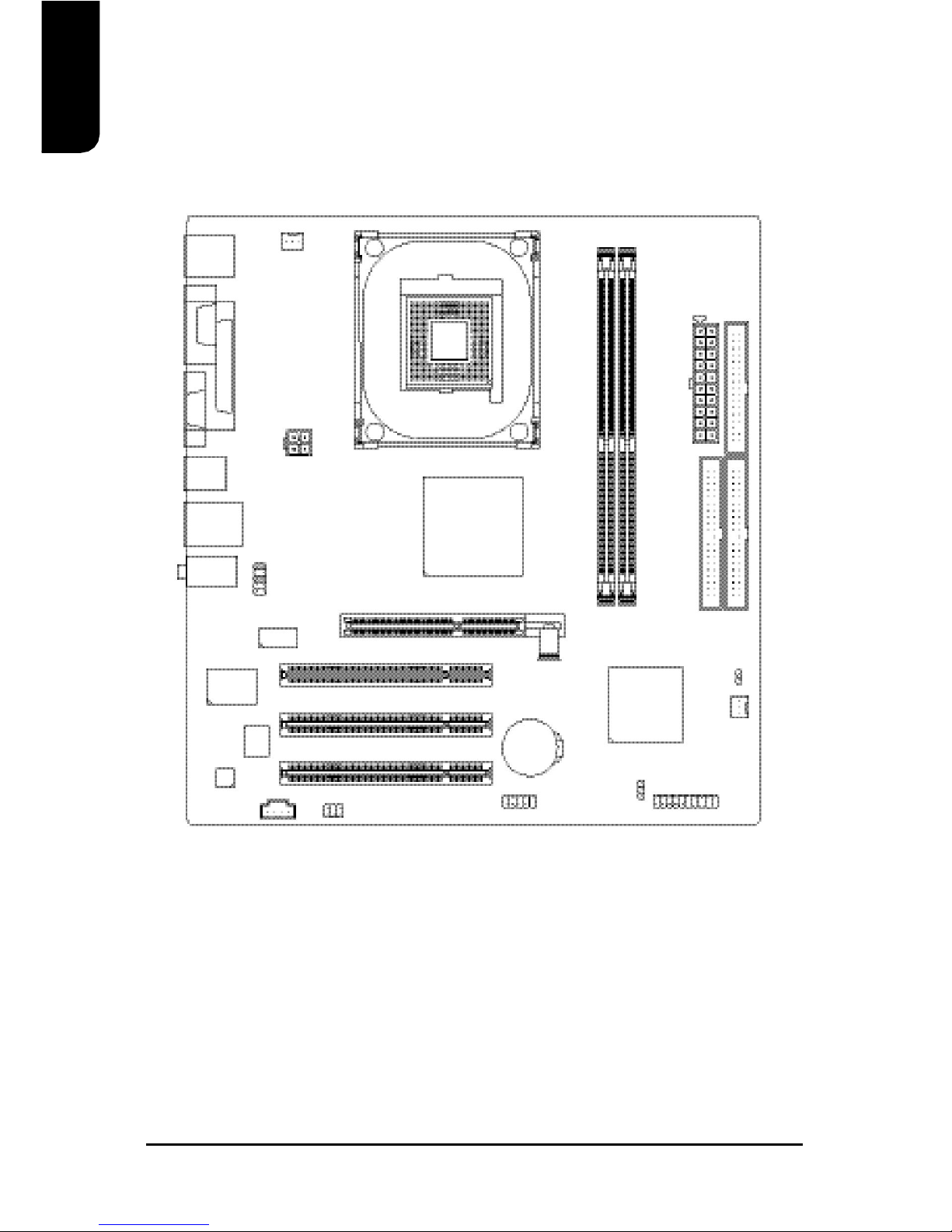
Motherboard Layout
XP-P4S8X-VM
KB_MS
COMA
ATX_12V
CD_IN
F_AUDIO
F_PANEL
BATTERY
SiS 964L
SiS 661GX
SOCKET 478
CPU_FAN
ATX
FDD
IDE2
PCI1
PCI2
PCI3
DDR1
CODEC
IT8705AF
BIOS
VGA
IDE1
CLR_CMOS
F_USB1
PWR_LED
USB
LAN
DDR2
LPT
ICS1883
AGP
SYS_FAN
AUDIO
R_USB
SUR_CEN

English
5
CPU Socket 478 for Intel® Pentium® 4 (Northwood, Prescott) with
HT Technology
Intel® Pentium® 4 800(overclock)/533MHz FSB
L2 cache depends on CPU
Chipset North Bridge: SiS® 661GX
South Bridge: SiS® 964L
Memory 2 184-pin DDR DIMM sockets, supports up to 2GB DRAM (Max)
Supports DDR400/DDR333/DDR266 DIMM
Supports only 2.5V DDR SDRAM
Slots 1 AGP slot support 4X/8X(1.5V) device
3 PCI slots support 33MHz & PCI 2.2 compliant
On-Board IDE 2 IDE controller provide IDE HDD/CD-ROM(IDE1, IDE2) with PIO,
Bus Master (Ultra DMA33/ATA66/ATA100/ATA133) operation modes
Can connect up to 4 IDE devices
On-Board Floppy 1 Floppy port supports 2 FDD with 360K, 720K,1.2M, 1.44M and
2.88M bytes
On-Board Peripherals 1 Parallel port supports Normal/EPP/ECP mode
1 VGA port, 1 Serial port (COMA)
6 USB 2.0/1.1 ports (4 x Rear, 2 x Front by cable)
1 Front Audio connector
1 PS/2 Keyboard
1 PS/2 Mouse
On-Board VGA Built-in SiS® 661GX Chipset
On-Board LAN Builit-in ICS1883 chipset
1 RJ45 port
On-Board Sound Realtek ALC655 CODEC
Support 2 / 4 / 6 channel
Line Out / Line In / Mic In
CD In connection
BIOS Licensed AWARD BIOS
Supports BIOSNow!
I/O Control IT8705AF
Hardware Monitor System voltage detect
CPU temperature detect
CPU/System fan revolution detect
Form Factor Micro-ATX form factor, 24.4cm x 23.0cm
1.1. Feature Summary
1. Product Introduction
The user manual provides steps related to quick installation. If you wish to view complete
product information, please select the " ", Open User Manual button located on the driver
CD or link to our website at http://www.axper.com to received the most up-to-date information.
6
English
PS/2
Keyboard
PS/2
Mouse
VGA
Parallel Port
COMA
1.2. I/O Back Panel and Connectors & Jumper Setting
1.2.2. Connectors & Jumper Setting
FDD (Floppy Disk Drive Connector)
The FDD connector is able to connect a single floppy disk drive via a FDD cable. Usually one
edge of the FDD cable is marked in red, please attach this marked edge to position 1 on the
connector.
IDE1 / IDE2 (IDE1 and IDE2 Connector)
The IDE connector is able to connect two IDE devices via an IDE cable and requires checking
of the IDE jumper setting. It is recommended that the hard drive be connected to the first IDE
connector while the optical drive be connected to the second IDE connector.
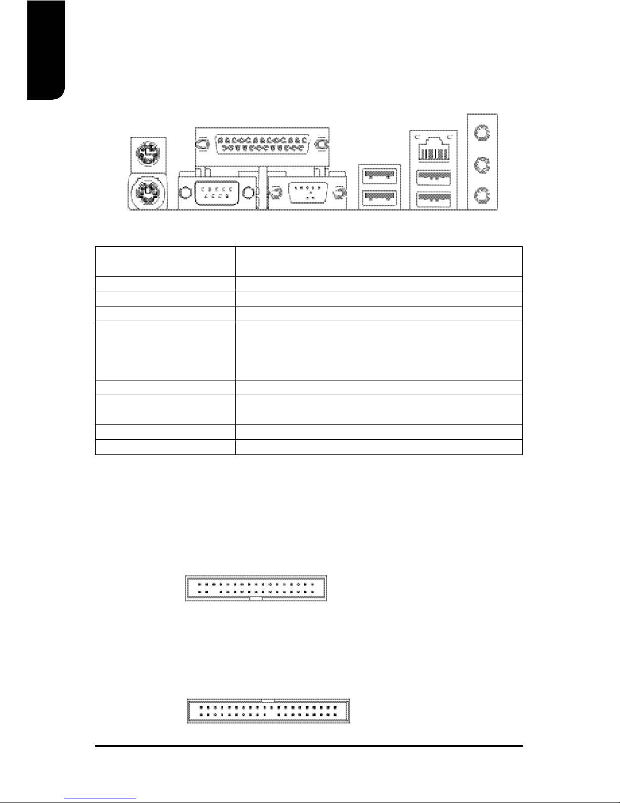
1.2.1. I/O Back Panel
PS/2 Keyboard Connects PS/2 standard keyboard and PS/2 standard
PS/2 Mouse connector mouse
Parallel port (LPT) Connects to printer
COMA (Serial port) Connects to serial-based mouse or data processing devices
VGA Port Connects to 15pin D-Sub device such as a monitor
USB Prior to use, please make sure that your system as well
(Universal Serial Bus Port) as the connected attachments support the USB interface.
If driver installation is required, please consult the USB
section of the user manual.
LAN (RJ45 LAN Port) Internet connection with speed of up to10/100Mbps
Line In Connects to optical devices, CD players and other audio
input devices
Line Out Connects to speakers or headphones
Mic In Connects to microphone
1
342
33
40 2
39
1
LAN
USB
Line Out
Mic In
Line In
USB
English
7
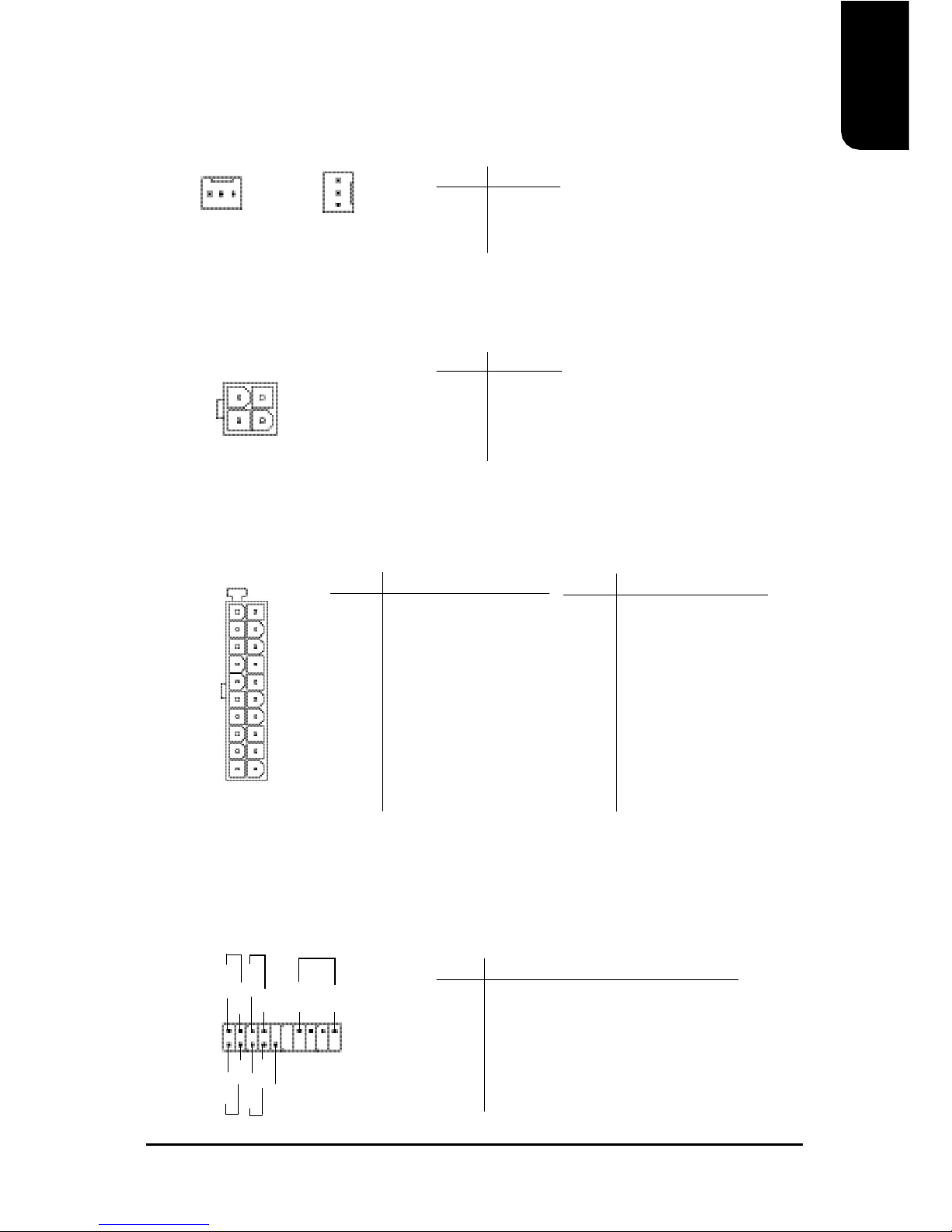
CPU_FAN (CPU Fan Power Connector); SYS_FAN (System Fan Power Connector)
The CPU_Fan power connector provides the largest amount of power to the CPU fan at
600mA. You can connect the casing fan to the SYS_FAN connector to enhance system cooling.
ATX_12V (+12V Power Connector)
The ATX_12V power connector provides power to the CPU. If this connector is not attached,
the system will not start.
ATX (ATX Power Connector)
The ATX power connector provides power to the motherboard. Prior to connection, please
make sure that the power supply is disconnected.
F_PANEL (Front Panel Control Connector)
The F_Panel Control Connector connects to certain connectors on the front panel of the
system casing such as IDE Hard Disk Active LED, speaker, reset, and power on/off connectors.
You can use the schematic diagram below as the basis for connection.
PIN SIGNAL
1 GND
2 GND
3 +12V
4 +12V
1
10
11
20
PIN SIGNAL
HD IDE Hard Disk Active LED
SPK Speaker Connector
RES Reset Switch
PW Power Switch
MSG Message LED/Power/Sleep LED
NC NC
PIN SIGNAL
1 3.3V
2 3.3V
3 GND
4 +5V
5 GND
6 +5V
7 GND
8 Power Good
9 5VSB (stand by +5V)
10 +12V
PIN SIGNAL
11 3.3V
12 -12V
13 GND
14 PS_ON (soft on/off)
15 GND
16 GND
17 GND
18 -5V
19 +5V
20 +5V
PIN SIGNAL
1 GND
2 +12V
3 Sense
341
2
1
2
19
20
HD-
HD+
RES+
RES-
NC
SPK-
MSG-
MSG+
PW-
PW+
SPK+
1
1
CPU_FAN
SYS_FAN
8
English
F_AUDIO (Front Audio Connector)
Connects to the audio connector located on the front panel of the system casing (dependent
on case design). When use of the front panel audio connector is required, please remove the
5-6 pin, 9-10pin jumper. Please note that use of only the front panel audio connector or the
rear panel audio connector is permitted.
CD_IN (Optical Drive Audio Connector)
Connects CD-ROM or DVD-ROM audio connector.
1
PIN SIGNAL
1 MIC
2 GND
3 MIC_BIAS
4 POWER
5 Front Audio (R)
PIN SIGNAL
6 Rear Audio (R)
7 Reserved
8 NO PIN
9 Front Audio (L)
10 Rear Audio (L)
PWR_LED
Connects to the system power LED indicator whereby the power is indicated as ON or OFF.
However, the indicator will flash when the system is suspended.
1
PIN SIGNAL
1 MPD+
2 MPD3 MPD-
PIN SIGNAL
1 CD_L
2 GND
3 GND
4 CD_R
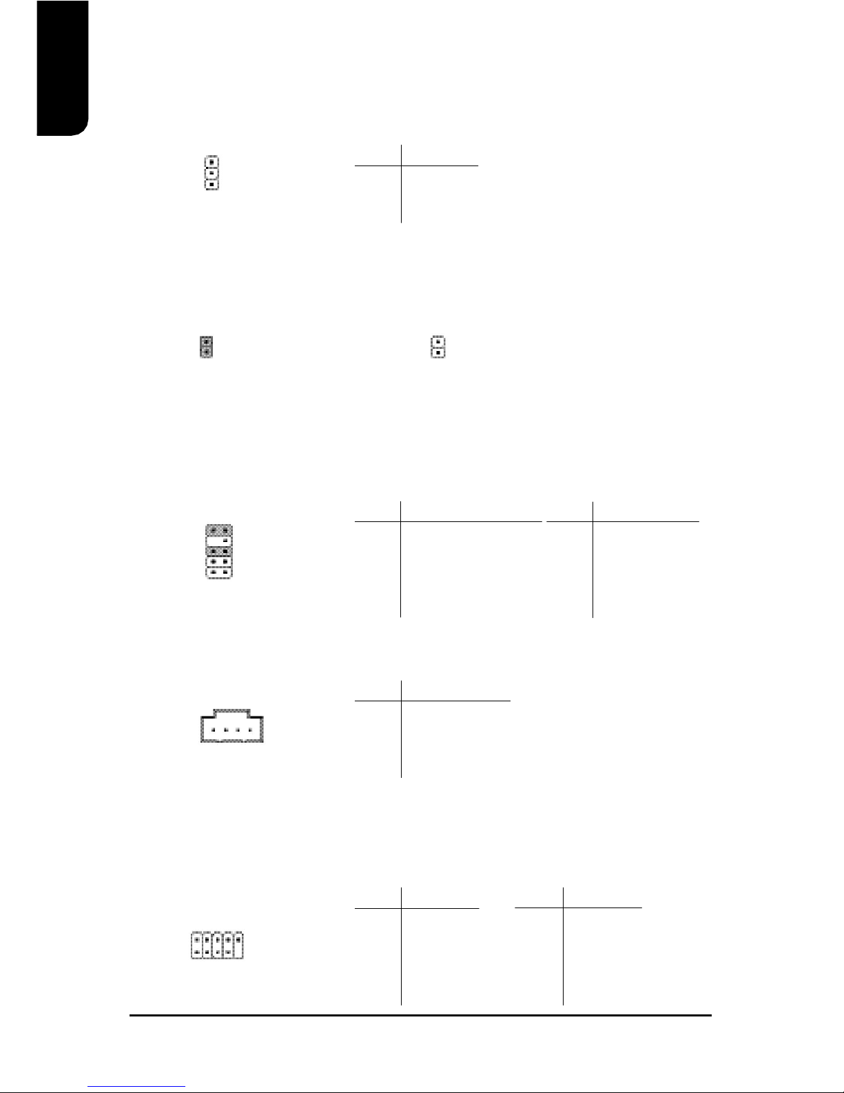
CLR_CMOS (Clear CMOS)
You can clear the motherboard CMOS with the jumper to return your system to its initial
status. To prevent improper usage, the jumper does not include the jumper plug. If you wish to
use the Clear CMOS function, please short circuit the 1-2Pin.
1
Open : NormalShort : Clear CMOS
1
F_USB1 (Front USB Connector)
Connects to the USB connector located on the front panel of the system casing (dependent on
case design). Note: Please make sure that each USB connection matches its designated
position. If connections are made incorrectly, the result can lead to inability to use the function
or even damage.
2 10
1
9
PIN SIGNAL
6 USB Dy+
7 GND
8 GND
9 NO PIN
10 NC
PIN SIGNAL
1 POWER
2 POWER
3 USB Dx4 USB Dy5 USB Dx+
1
10
9
2
 Loading...