

Gigatelecom SC-7070 Service Manual

Service Manual SC-7070, Rev 1.0 24 September 2003
Service Manual
SC-7070
Single Mode Digital CDMA Telephone
Gigatelecom Proprietary
Confidential Treatment Requested
Rev 1.0
26, August, 2003
Gigatelecom Corporation
- 1 -
GSD556 SM_01.doc Gigatelecom Proprietary

Service Manual SC-7070, Rev 1.0 26, August, 2003
TABLE OF CONTENTS
1. Introduction ................................................................................................................................. 3
2. Specification................................................................................................................................ 4
2.1 GSD556 Specifications............................................................................................................ 4
2.2 Battery Specifications .............................................................................................................. 5
2.3 AC Charger Specifications ....................................................................................................... 5
3. Technical Description ................................................................................................................. 6
3.1 Overview.................................................................................................................................. 6
3.2 RF part Description.................................................................................................................. 9
3.2.1 Description of Frequency Synthesizer Circuit.................................................................... 9
3.2.2 Description of Rx Part Circuit .......................................................................................... 10
3.2.3 Description of Tx Part Circuit........................................................................................... 12
3.3 Logic Part Description............................................................................................................ 15
3.3.1 Keypad/LCD, Receptacle Part(CON451) ........................................................................ 15
3.3.2 Voice Processing Part .....................................................................................................15
3.3.3 Mobile Station Modem( ; MSM5100, U301)..................................................................... 15
3.3.4 Memory Part (U351) ........................................................................................................17
3.3.5 Power Supply Part........................................................................................................... 17
3.4 Power Up Sequence.............................................................................................................. 19
3.4.1 Place a Battery Pack ....................................................................................................... 19
3.4.2 Press and Hold [END] Key .............................................................................................. 19
3.4.3 Regulators Activated ....................................................................................................... 19
3.4.4 VCTCXO Activated..........................................................................................................19
3.4.5 Reset Pulses Generated ................................................................................................. 19
3.4.6 MSM5100(U301) Starts ................................................................................................... 19
3.4.7 Phone Wakes Up............................................................................................................. 19
4. Servicing Tools ......................................................................................................................... 20
5. Measurement............................................................................................................................. 22
5.1 Measurement Configuration .................................................................................................. 22
5.2 CDG2 MENU ......................................................................................................................... 23
5.3 Hardware Control MENU .......................................................................................................23
6. Assembling and Disassembling.............................................................................................. 24
7. Replacing Parts......................................................................................................................... 31
GSD556 SM_01.doc
- 2 -
Gigatelecom Proprietary

Service Manual SC-7070, Rev 1.0 26, August, 2003
1. Introduction
This manual provides the technical information to support the service activities of SC-7070 Single
mode Digital CDMA Telephone.
This manual is supplied in the electronic format for easy distribution and reference.
Also refer to the following documents:
-. Service Guide of SC-7070 phone
GSD556 SM_01.doc
- 3 -
Gigatelecom Proprietary
Service Manual SC-7070, Rev 1.0 26, August, 2003
2. Specification
This chapter provides the product configuration and product specifications of the SC-7070
2.1 GSD556 Specifications
Item 800MHz Band
1 Type Approval Number
2 Radio Frequency
3 Number of Channels 20 (CDMA)
4 Duplex Spacing 45MHz
5 Digital Mode
5.1 Channel Spacing 1.23MHz
5.2 Frequency Stability +/-300Hz
5.3 RF Output Power 23dBm ~ 27dBm
5.4 Receiver Sensitivity ≤ -104dBm
5.5 Modulation/Demodulation OQPSK/QPSK
6 Operating Temperature -20 to +60 degrees Celsius
7 Power Source Lithium Ion Battery 3.7V, 550mAh
8 Dimensions Approx. 84× 46× 20 mm
9 Weight Approx. 78 g
Power Management
10
11 Features
12 Protocol IS-95A / IS-95B/ IS-95C
13 Software Version
14 Production
Talk Time (up to) Digital : 150min (10dBm/Voice activity 44%)
Standby Time (up to) Digital : 130 h (Slot mode 1)
Tx : 824 to 849MHz
Rx : 869 to 894MHz
-. Two-Way Short Message Service (SMS)
-. Vibrating Alert
-. Multilingual (English/Chinese)
-. Voice Memo
-. 260K Color TFT LCD
-. BLUE Color Indicator LED
-. 40 Poly Melody
GSD556 SM_01.doc
- 4 -
Gigatelecom Proprietary

Service Manual SC-7070, Rev 1.0 26, August, 2003
2.2 Battery Specifications
Items
1 Battery Type Lithium Ion Battery
2 Battery Voltage 3.7V
3 Battery Capacity 550mAh
4 Recharging Time With Charger 3Hr MAX. at 550mAh Li-ion Battery
2.3 AC Charger Specifications
Items
1 Input Voltage AC100 - 240V +/- 10%, 50/60Hz
2 Output Voltage DC 4.2V
3 Output Current 600mA
GSD556 SM_01.doc
- 5 -
Gigatelecom Proprietary
Service Manual SC-7070, Rev 1.0 26, August, 2003
3. Technical Description
3.1 Overview
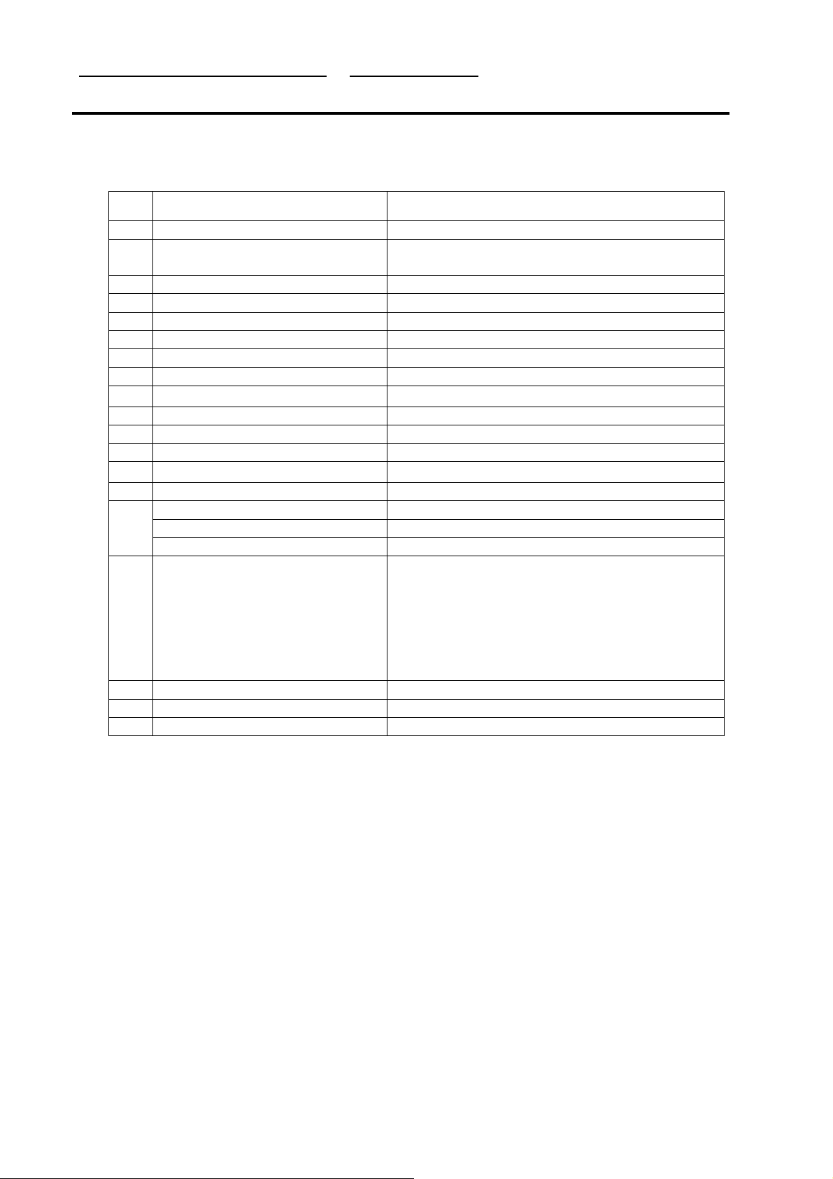
The Tx and Rx part employs the Super-Heterodyne system. The Tx and Rx frequencies are
respectively 824.04~848.97MHz and 869.04~893.9MHz. The block diagram is shown in Figure 3.1.
RF signals received through the antenna are fed into the low noise amplifier (LNA, U651) through
the duplexer(DPX651). Then, they are combined with the signals of local oscillator (VCO, U702) at
the down conversion mixer(U602) in order to create the intermediate frequency (IF). The IF signal
created is sent out to each bandpass filter (BPF) through the CDMA switching, and then fed into
S1M8656A01-F0T0(U601). In S1M8656A01-F0T0(U601), the IF signal is changed into baseband
signal. Then, this signal is changed into the digital signal by the analog to digital converter (ADC,
A/D Converter), and the digital circuit part of the MSM5100(U301) processes the data from ADC.
The digital processing part is a demodulator.
In the case of transmission, The RFT3100(U501) receives digital signal from the MSM5100
(U301). In MSM5100(U301), the digital signal is changed into analogl signal by the digital to
analog converter (DAC, D/A Converter), and then the baseband quadrature signals are
upconverted to the Cellular IF frequency bands in RFT3100(U501).The Tx AGC in RFT3100
(U501) is designed to be gain-controlled from 85dB dynamic range. In RFT3100(U501), the Tx IF
frequency mixed with RF local frequency is created Tx RF frequency. After that, the RF signal is
amplified by the Power Amp in order to have enough power for radiation after going through the
attenuator. Finally, the RF signal is sent out to the cell site via the antenna after going through the
duplexer(DPX651).
(ANT2)
S1M8656A01-F0T0(U601)
RF
RX Baseband IF Converter
SUBSYSTEM
RFT3100 (U501)
TX Baseband IF Converter
(SPK)
Memory
and
User
Interface
MSM5100 (U301)
Mobile Station Modem
(MIC301)
Figure 3.1 Typical Subscriber Unit Block Diagram
GSD556 SM_01.doc
- 6 -
Gigatelecom Proprietary
Service Manual SC-7070, Rev 1.0 26, August, 2003
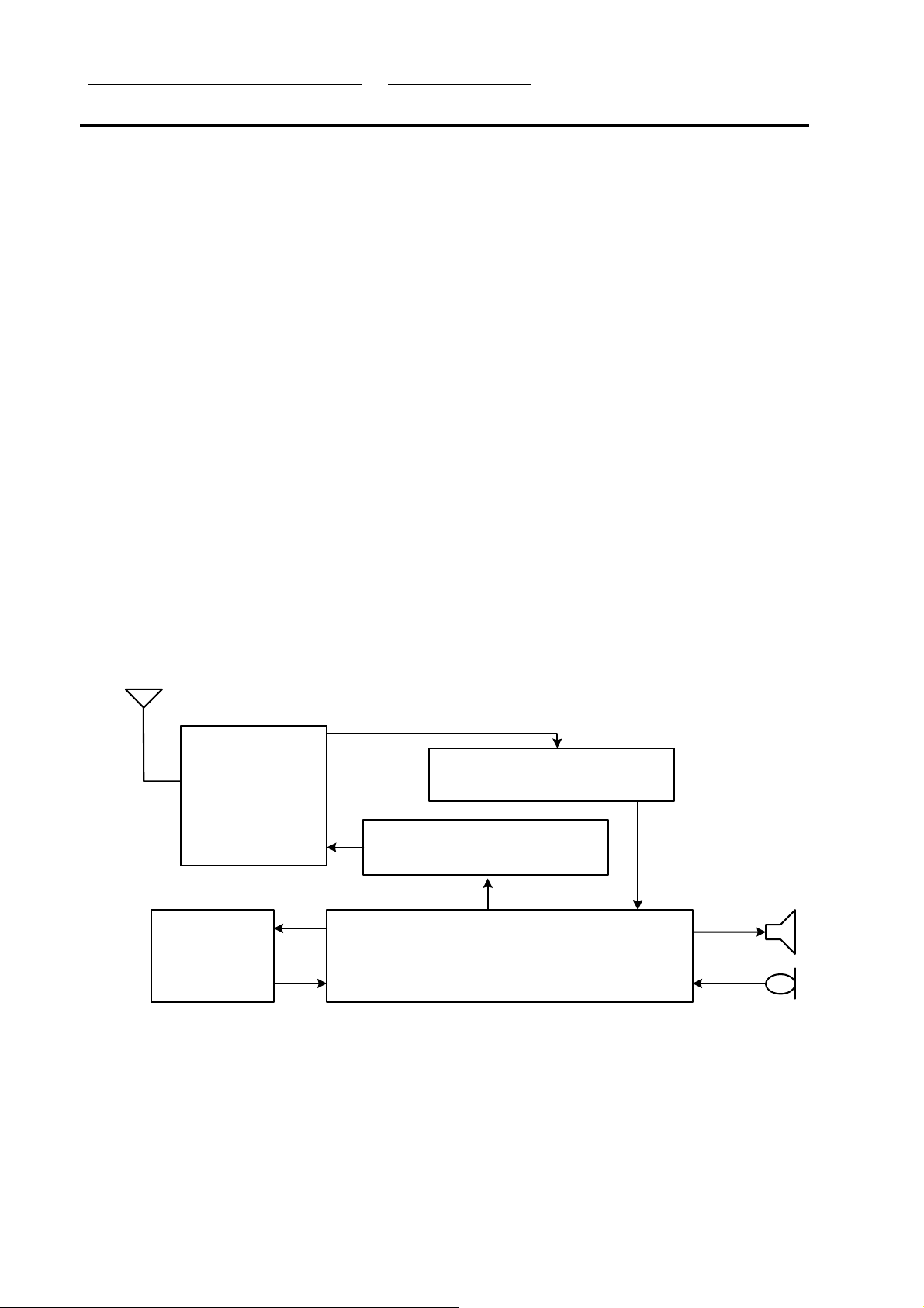
GSD556 SM_01.doc
Figure 3.2 SC-7070 Main Board Front View
- 7 -
Gigatelecom Proprietary
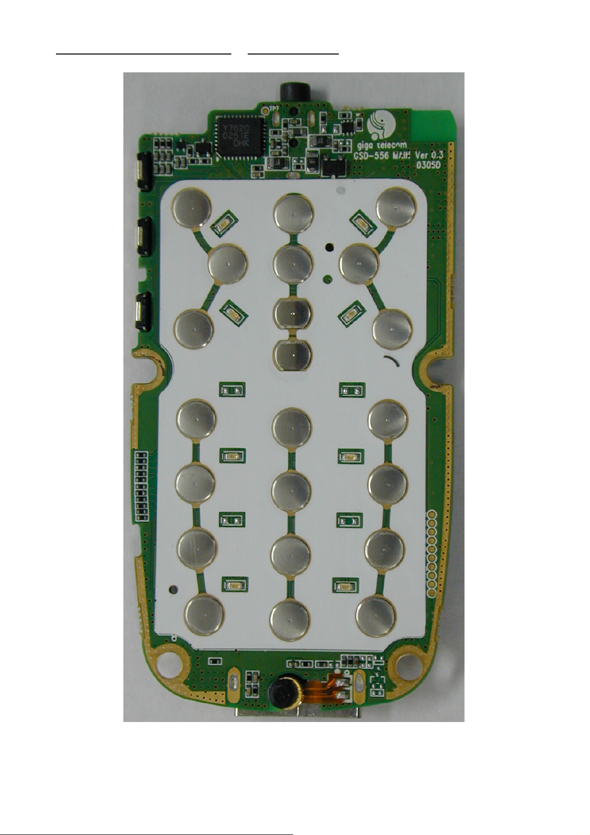
Service Manual SC-7070, Rev 1.0 26, August, 2003
Figure 3.3 SC-7070 Main Board Front View
GSD556 SM_01.doc
- 8 -
Gigatelecom Proprietary

Service Manual SC-7070, Rev 1.0 26, August, 2003
3.2 RF part Description
The RF part consists of power part, synthesizing part, transmission and reception part.
3.2.1 Description of Frequency Synthesizer Circuit
The UHF band frequency synthesizer is composed of an indirect frequency synthesizer, Phase
Locked Loop (PLL IC, U701), VCO(U702) with the center frequency of 966.88MHz for CDMA
mode, Loop Filter and a directional coupler. PLL IC(U701)’s phase detector compares the
reference clock frequency (19.68MHz, TCXO(U705) clock) divided down to 10kHz by the
reference divider with a signal from the VCO(U702) divided by the PLL IC(U701) main divider.
Thus generating local oscillation signals with zero phase difference. These local oscillation signals
are used both for Tx and Rx. The local oscillation signals are separated for Tx and Rx by the
directional coupler. There are Rx and Tx IF synthesizers, respectively. The Tx IF synthesizer is
composed of the RFT3100(U501), Tx Tank circuit, and the loop filter. The Tx phase detector within
the RFT3100(U501) receives the oscillation signals from the tank circuit generating 260.76MHz Tx
IF. The Rx IF synthesizer is composed of the PLL, the S1M8656A01-F0T0(U601), the Rx Tank
circuit, and the loop filter. The signal generated from the tank circuit is sent through the
S1M8656A(U601) to the dual mode PLL’s phase detector. The PLL IC(U701) generates the control
voltage to the loop filter such that 170.76MHz Rx IF is synthesized.
Voltage Control Temperature Compensation Crystal Oscillator (VCTCXO, U705)
The temperature variation of mobile phone can be compensated by VCTCXO(U705). The
reference temperature of a mobile phone is -20~+60 °C. The VCTCXO(U705) receives
frequency tuning signals called TRK_LO_ADJ from MSM as 0.5V~2.5V DC via R and C
filter in order to generate the reference frequency of 19.68MHz and input it into the
frequency synthesizer of UHF band. Frequency stability depending on temperature is
within ±1.5 ppm.
RF Frequency Synthesizer
RF PLL loop is consisted of the RF PLL Synthesizer in the PLL IC(U701), loop filter, VCO
(U702) and VCTCXO(U705). It generates the RF local frequency of 954.38 ~979.38 MHz.
RX IF Frequency Synthesizer
Rx IF PLL Loop is consisted of the Rx IF PLL Synthesizer in the PLL IC(U701), VCO
included in the S1M8656A01-F0T0(U601), loop filter and VCTCXO(U705). The Rx VCO
output included in the S1M8656A01-F0T0(U601) oscillates twice Rx IF frequency of
170.76MHzand then generates the RX IF frequency of 85.38MHz by dividing the VCO
output frequency by two.
TX IF Frequency Synthesizer
The Tx IF PLL Loop is consisted of the Tx IF PLL synthesizer, VCO that is internally
installed in the RFT3100(U501), loop filter and VCTCXO(U702). The Tx VCO output
included the RFT3100(U501) generates Tx IF local frequency of 260.76MHz and then
generates the Tx IF frequency of 130.38MH by dividing the VCO output frequency by two.
GSD556 SM_01.doc
- 9 -
Gigatelecom Proprietary

Service Manual SC-7070, Rev 1.0 26, August, 2003
3.2.2 Description of Rx Part Circuit
Cellular Receiver covers the frequency band of 869 ~ 894 MHz. IF frequency is 85.38MHz and
super-heterodyne circuit is used. The RF signal received is sent out to the RF AMP (LNA, U651)
via a duplexer(DPX651) for amplification and then, is sent out to the down mixer(U602). Here, the
RF signal is mixed with the VCO(U702) signal of 954.38 MHz ~979.38 MHz. IF signal down
converted by the down mixer(U602) are sent out to IFSAW Filter(F601) and only required signals
are selected. The signal that has passed the IF SAW filter(F601) is fed into AGC AMP that is
controlled by the power density modulated (PDM) signal of the MSM5100(U301) based on the
strength of received signal. This AGC AMP is tuned into the level corresponding to the input
window (input sensitivity) of the base band analog processor (S1M8656A01-F0T0, U601). The
AGC AMP controls Rx power level with 90dB dynamic range. The signal entered to
S1M8656A(U601) is converted again to 1.2288 MHz base band signal. To do second frequency
conversion, the frequency synthesizer in S1M8656A (U601) oscillates VCO(U702) at 170.76MHz
and these signals are divided by two in order to create 85.38MHz In-phase and Quadrature-phase
signal. These 85.38MHz I/Q oscillator signals are sent to MSM5100(U400) and used to convert RX
IF signals to I/Q base band signal. I and Q baseband signals are respectively sent out to the
analog digital converter via a low pass filter.
Duplexer (DPX651)
The duplexer(DPX651) consists of the Rx bandpass filter (BPF) and the Tx BPF which
have the function of separating Tx and Rx signals in the full duplex system for using the
common antenna. The Tx BPF is used to suppress noises and spurious out of the Tx
frequency band. The Rx BPF is used to receive only Rx signal coming from the antenna,
which is usually called preselector. Its main function is to limit the bandwidth of spectrum
reaching the LNA(U651) and down mixer(U602), attenuates receiver spurious response
and suppress local oscillator energy. As a result, the frequency sensitivity and selectivity of
mobile phone increase.
LNA (U651)
The characteristics of Low Noise Amplifier (LNA, U651) are low noise figure, high gain,
high intercept point and high reverse isolation. The frequency sensitivity characteristic of
mobile phone is mostly determined by LNA(U651).
Rx RF SAW Filter (F602)
The main function of Rx RF SAW filter(F602) is to attenuate mobile phone spurious
frequency, attenuate direct IF frequency pick up, attenuate noise at the image frequency
originating in or amplified by the LNA(U651) and suppress second harmonic originating in
the LNA(U651). The Rx RF SAW filter(F602) is usually called image rejection filter.
Down Mixer (U602)
The Down Mixer(U602) performs frequency translation by multiplying two signals. The
Downconversion mixer employed in the Rx path has two distinctly different inputs. One is
RF and the other is Local Osillator (LO) port. The RF port senses the signal to be
downconverted and the LO port senses the periodic waveform generated by the local
osillator
GSD556 SM_01.doc
- 10 -
Gigatelecom Proprietary
 Loading...