

Gigatech K-350R Owner's Manual Installation And Operation
HF COLOR VIDEO INTERCOM
WITH RECORDING
,
OWNERS MANUAL
INSTALLATION AND OPERATION
K-350R KIT

TABLE OF CONTENTS
1
1
2
2
4
4
5
5
6
8
9
9
9
10
12
14
14
16
16
17
19
19
21
22
23
23
25
26
27
27
28
28
29
29
29
30
31
33
K-350R KIT VIDEO INTERCOM SYSTEM
1.K-350R KIT Introduction
2.K-350R KIT Parts Identification
2.1.Main Monitor
2.2.Door Camera
2.3.K-350R KIT Packaging
3.K-350R KIT Installation
3.1. Positioning the devices
3.2. Installation
3.3. Door Release Options
4. K-350R KIT read before operation
4
XPANSION OPTIONS
System Layout 1
System Layout 2
1. Expansion video monitor (EX-350H)
1.1.EX-350H Identification
1.2.EX-350H Installation
1.3.EX-350H Operation
2. Expansion audio monitor (EX-350A)
2.1.EX-350A Identification
2.2.EX-350A Installation
2.3.EX-350A Operation
3.Door camera (EX-350D)
3.1.EX-350D Identification
3.2.EX-350D Installation
3.3.EX-350D Operation
4.
4.1.EX-350V Contents
4.2.EX-350V Operation
4.3.Assembly procedure
TECHNICAL SPECIFICATIONS
TROUBLE SHOOTING
.1. Attention
4.2. On screen menu icons
4.3. Setup menu
4.4. Intercom function operations
4.5. function
4.6. Video/photo playback menu
E
Metal Door Camera Housing (EX-350V)
Privacy

K-350R KIT VIDEO INTERCOM SYSTEM
1. K-350R KIT introduction
Thank you for purchasing this Video Intercom System. This advanced
system not only allows you to identify and communicate with visitors at
the door and allows for remote door strike release, it can also record the
video intercom communication on a micro SD card for later playback.
This system has an interactive on screen menu for easy operation by
touch sensitive buttons located on the two sides of the screen. Please
read thru this manual for all detailed functions.
This package consists of a main monitor and a doorbell camera unit and
a power supply.
This intercom system is capable of expanding up to a maximum of 4
indoor monitors and 2 doorbell cameras in a standard system. With
additional HB-140 home-run expansion modules, the total number of
monitors can be extended up to 8 total.
K-350R Video intercom systemIntroduction V
1
2011-01
2.K-350R KIT Parts Identification
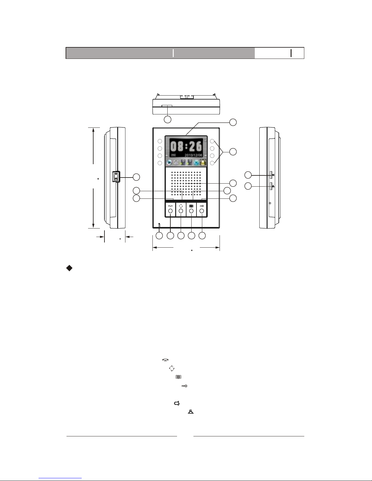
2.1. Main Monitor
4
10 1112139
5
6
8
7
14
15
16
178mm
(7.0)
36mm
(1.42)
118mm
(4.65)
1. Micro SD card slot socket
2. 3.5" Color TFT Screen
3. Touch sensitive buttons (4 on each side, unmarked)
4. Speaker
5. In use LED
6. Monitor LED
7. Intercom LED
8. Speach open LED
9. Microphone
10. Cut-off button( )
11. Intercom button( )
12. Monitoring button( )
13. Door release button( )
14. Power switch
15. Bell Volume tuner( )
16. Speaker Volume tuner( )
K-350R Main monitor identification:
2
1
3
2
K-350R Video intercom systemIntroduction V12011-01
Wiring terminals
PT1
PT2
DG1
DG2
OUT+
OUT-
DR2
DR1
POWER
<+>
<->
136mm
(5.35)"
89mm
(3.5)"
8.4mm(0.33)"
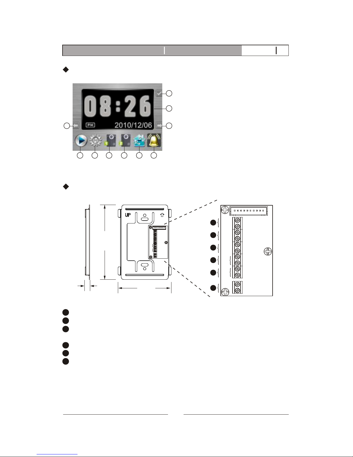
Wall mount bracket
PT1
PT2
DG1
DG2
OUT+
OUT-
DR2
DR1
POWER
<+>
<->
Main monitor wall mount bracket
Magnetic switch sensor connection: for door status detection
External chime or light indicator connection: for optional third party device
Expansion monitor connection: for more indoor monitor expansion
(w/polarity)
Door camera connection(2): to the 2nd door camera terminals(no polarity)
Door camera connection(1): to the 1st door camera terminals(no polarity)
Power adapter connection
1
2
3
4
5
6
1
2
3
4
5
6
K-350R Main menu identification:
5 6 7 8 9 10
1
34
1. Confirm
2. Video and menu display area
3. Tab right
4. Tab left
5. Play
6. Setup
7. 1st doorbell camera
8. 2st doorbell camera
9. Paging other monitor
10. Chime enable or disable
2
3
K-350R Video intercom systemIntroduction V12011-01
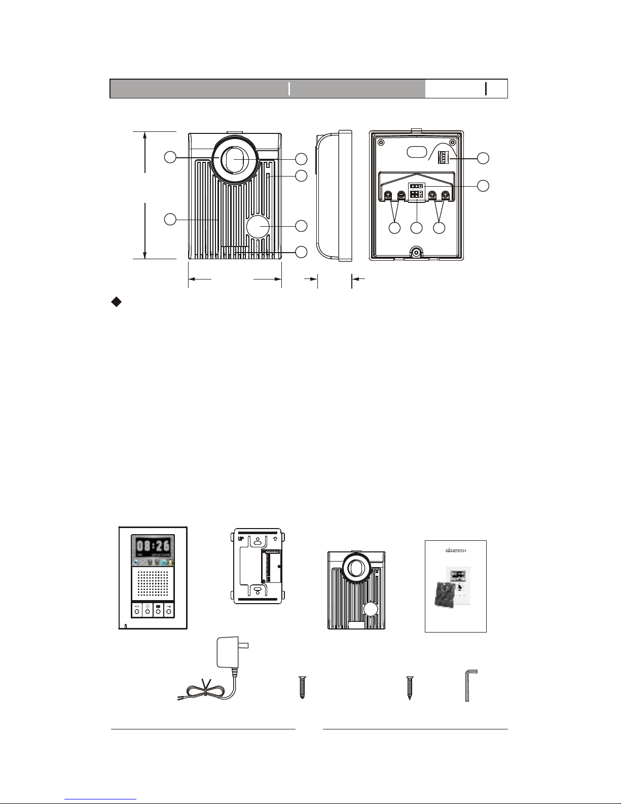
2.2. Door Camera
130mm
(5.12)"
36mm
(1.42)"
1. White LED Illumination
2. Speaker
3. 1/3" Color CCD
4. Microphone
5. Call button
6. Screw cover
7. CCD view angle knob
(-6 degrees, 0 degrees, 8 degrees, 16 degrees)
8. Jumper 2 (enable/disable light senor)
9. Jumper 1 (dry contact or current output selection)
10. Wire to door strike
11. Wire to main Monitor
K-350R Door Camera identification:
98mm
(3.86)"
JP1
JP2
1
2 3 4
3
4
5
2
6
7
8
910 11
Door camera
2.3.K-350R KIT Packaging
X1X1
Main monitor
X1
Wall mount bracket
PT1
PT2
DG1
DG2
OUT+
OUT-
DR2
DR1
POWER
<+>
<->
X1
Manual
Adaptor
X1
X4
White wall
mount screws
X1
X4
Flat head screws
1
security
screw wrench
4
K-350R Video intercom systemIntroduction V12011-01
HF COLOR VIDEO INTERCOM
WITH RECORDING
,
OWNERS MANUAL
INSTALLATION AND OPERATION
K-350R KIT
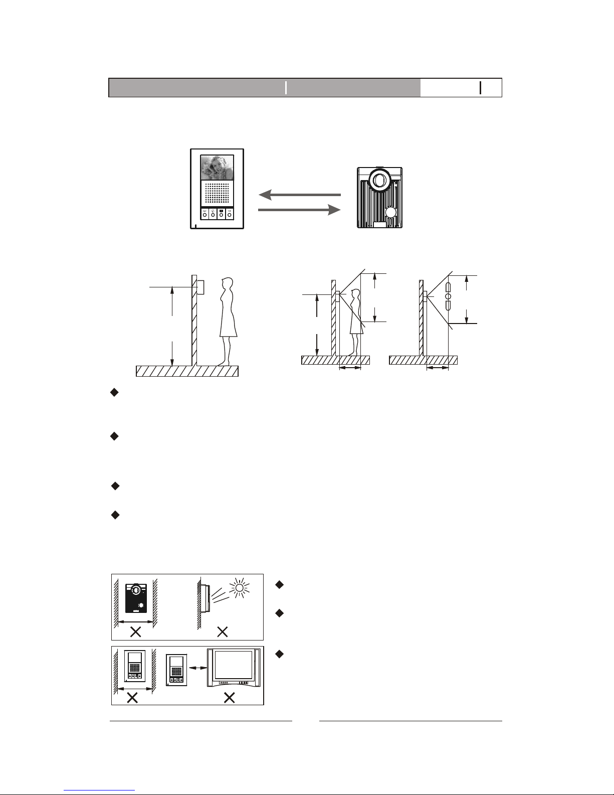
View Angle:Proper height:
The proper height of monitor or door camera is 160~170cm(63"~67")
from the ground. This may vary on each installation. View range should
be actively tested before complete.
Viewing window of door camera is about 70cm up-n-down, and 100cm
left-n-right.
3. K-350R KIT Installation
3.1. Positioning the devices
NOTE 1: Wiring distance
NOTE 2: the installation environment
170cm
(66.9)"
50cm(19.7)" 50cm(19.7)"
70cm
(27.6)"
100cm
(39.3)"
Main monitor
165cm
(64.9)"
From main monitor to door camera: Maximum of 100m(328 feet) with
AWG18 normal 2-wrie parallel wires or CAT-5 cable.
From monitor to monitor (every section): Maximum of 100m(328 feet)
with AWG22normal 2-wrie parallel wires or CAT-5 cable.
Door camera
Please avoid installation in an enclosed
environment as this may cause feedback.
Please avoid installation in direct sunlight
as this can cause a blurry picture or dark
shadows on subjects facing the camera.
Please avoid wire installation near other
power or signal lines and avoid placing
units close to high power appliances as
this may cause audio/video interference.
5
K-350R Video intercom systemIntroduction V12011-01
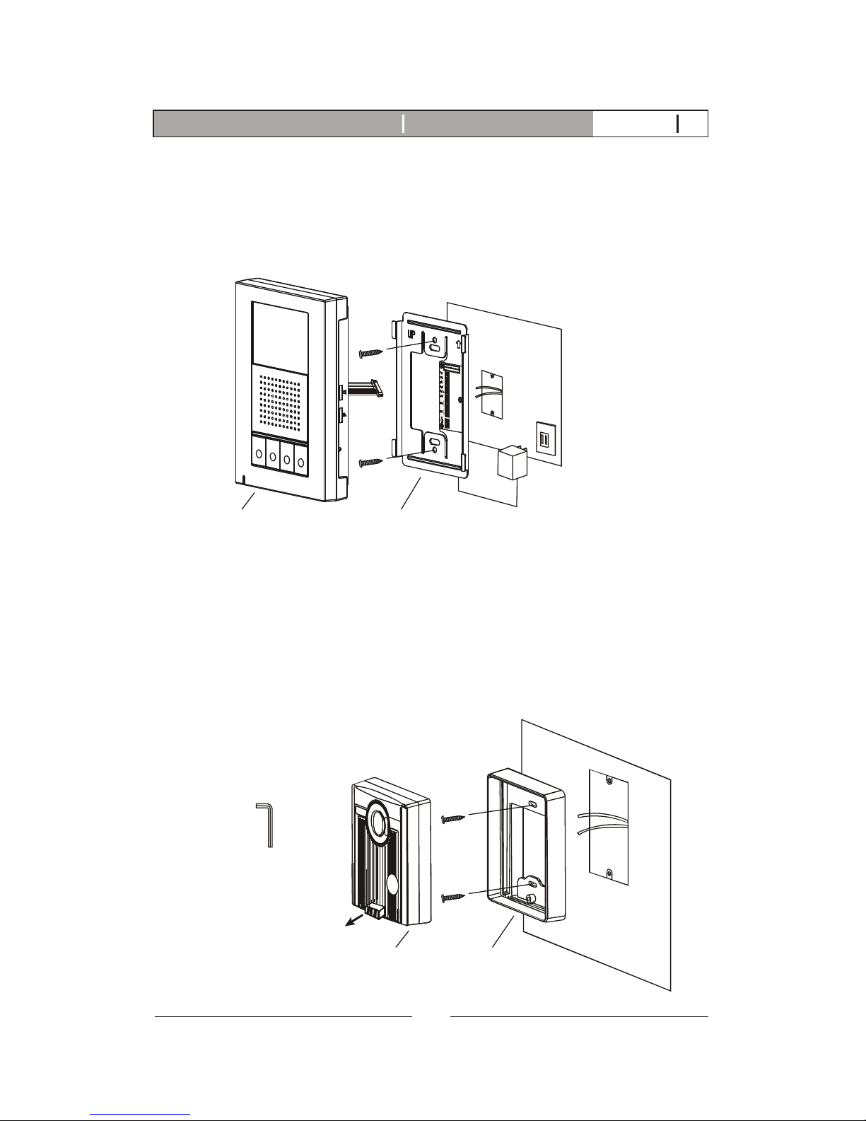
A. Fasten the wall mount bracket using the provided hardware.
B.Fasten wires on terminals accordingly. (Refer to STAGE 3)
C. Plug pin wires and mount the monitor unit on bracket.
3.2. Installation
STAGE 1: Installation of main monitor
Do not plug power
at this stage.
Wall mount bracketMonitor
A. Use security screw wrench disassemble screw and remove door camera
unit from bracket.
B. Fasten wall mount bracket on position.
C. Fasten wires on terminals and select jumpers for desired function.
(refer to STAGE 3)
D. Mount door camera unit on bracket, secure the assembly screw.
STAGE 2: Installation of the door cameras
Door camera Bracket
Pull out screw cover
to access the screw
security screw wrench
6
K-350R Video intercom systemIntroduction V12011-01
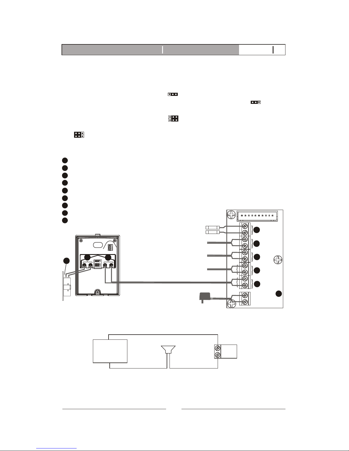
STAGE 3: Wiring and settings
PT1
PT2
DG1
DG2
OUT+
OUT-
DR2
DR1
POWER
<+>
<->
JP1
JP2
1 2 3 4
Main monitor
Wiring terminal
Red
Black
1
2
4
5
door camera
Wiring terminal
To expansion monitor
3
6
Terminals for magnetic switch (optional)
Terminals for external chime (optional)
Terminals for expansion monitor (w/polarity)
Terminals for the 2nd door camera (no polarity)
Terminals for the 1st door camera (no polarity)
Terminals for power adapter
Terminals to main monitor (no polarity)
Terminals for door strike
Electric Lock
1
2
3
4
5
6
7
8
9
7
8
External chime(optional)
To the 2nd door camera
Magnetic switch(optional)
9
A. Wire the system from door camera terminals to monitor terminals
accordingly.
B. Select and plug JP2 to its RIGHT( ) to disable LED illumination of the
doorbell camera when it's activated. Factory setting is LEFT( ) which
enables automatic LED illumination.
C. Select and plug JP1 to its RIGHT( ) for direct current output control
(12VDC 300mA) directly for a strike. Factory setting has JP1 to its LEFT
( ) for dry contact bridge control.(Refer to 3.3 Door Release Options)
D. External chime wiring diagram refer to figure 1.
DG1
DG2
Figure 1: External chime wiring diagram (DC or AC power supply)
POWER
External chime
NOTE:External chime(DG1,DG2) provide as a normal open dry contact
with no polarity, allowing maximum by-pass current of AC24V or
DC24V 1A.
AC24V or
DC24V 1A
7
K-350R Video intercom systemIntroduction V12011-01
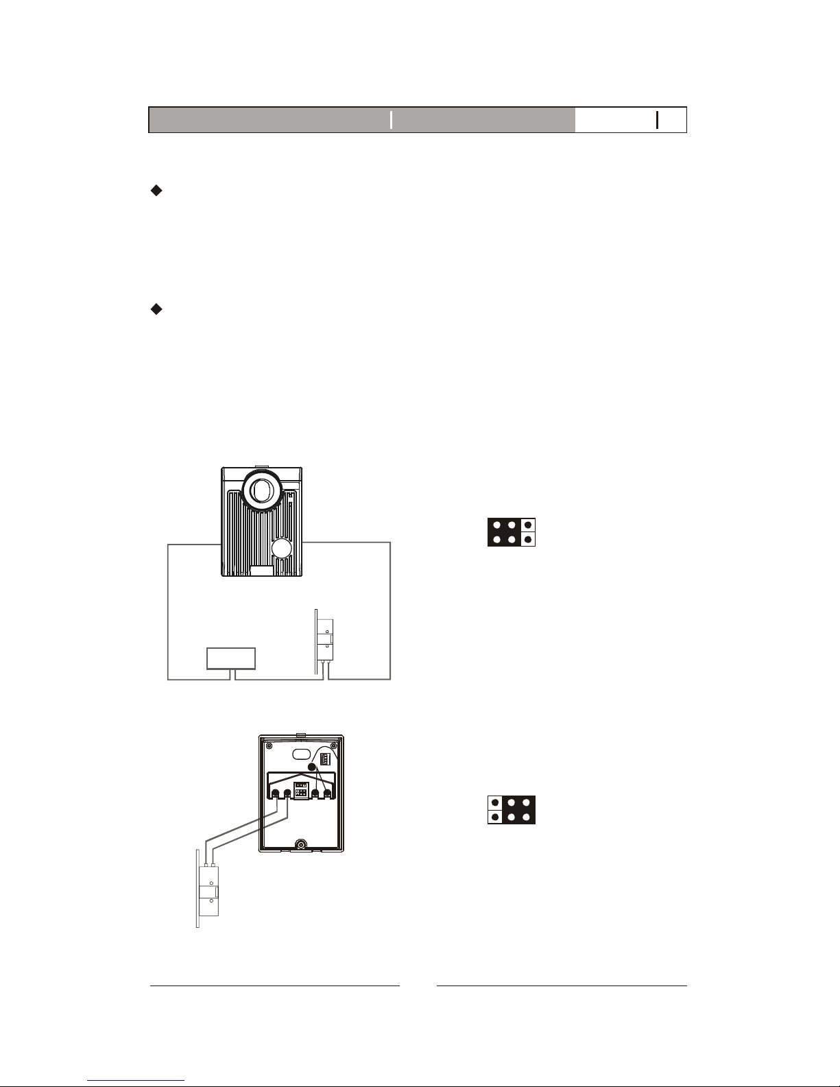
Each Door Camera on the system is able to operate and release one
electric lock. On a full system with 2 door cameras, the user is able to
release up to two electric locks. The system can only release one electric
lock at a time, depending on which door camera the call originated from.
There are two door release wiring options that work with the Video
Intercom System.
The system can either provide a normally open dry contact (figure 1), or
can be configured to give power (12V DC 300mA) straight to an electric
lock that is within the power requirements (figure 2). If you are using
power from the system (figure 2), It is necessary to use an electric lock
that requires less than 300mA of power to engage the strike.
Electric Lock
Power for Lock
Figure 1: Door Release Option 1 (Additional power supply)
Door camera
12/24V DC
1 Amp Max
NOTE: When jumper setting is left
(factory setting), the DOOR RELEASE
terminals provide as a normal open
dry contact with no polarity, allowing
maximum by-pass current of AC24V
or DC24V 1A.
3.3. Door Release Options
JP1
Figure 2: Door Release Option 2 (Using power from the system)
Electric Lock
JP1
JP2
1 2 3 4
7
Door camera
NOTE: When jumper setting is right,
the DOOR RELEASE terminals provide
current output of maximum 12VDC
300mA.
JP1
8
K-350R Video intercom systemIntroduction V12011-01
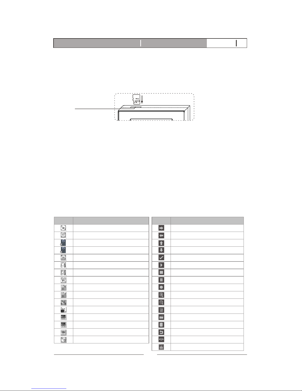
4. K-350R KIT read before operation
4.1. Attention
A. Micro SD card, SDHC(High Capacity SD card), is not included in this
product package.
B. Insert SD card properly. The SD card can be 2GB to 16GB memory size.
C. The video quality is 720x480 pixels, every recording (20 sec. a section)
takes about 15M memory size. Every photo takes about 130KB memory
size (So for a 4 GB card, it can hold about 260 Videos or 25,000 pictures).
D. If SD memory is full, new recording will overlay the oldest section.
Backup SD card memory is necessary.
E. Power on the machine, you will see main menu display on screen, blue
LED of the call button at doorbell camera on.
F. Menu display will turn off after 90 seconds of standing by.
G. There is a power reserve for 12 hours for clock adjustments. after 12
hours of the unit being powered off, the time settings will revert back
to default settings and the user will have to set the time again.
4
HC
m
i
cro
S
SD card socket
4.2. On screen menu icons
SD
ICON FUNCTION
Play
Setup
1st doorbell camera
2nd doorbell camera
Paging other monitor
Chime
Chime disable
Set clock
Door status-BELL
Door status-LED
Video recording mode
photo recording mode
PAL
NTSC
Format SD card
Escape to MAIN menu
Tab right
Tab left
Tab up
Tab down
Confirm
Play
Stop
Pause
Record
Zoom in
Zoom out
Tilt view
Video log
Delete video
Escape to MAIN menu
Off
SD card in place
ICON FUNCTION
9
K-350R Video intercom systemIntroduction V12011-01
 Loading...