

Gigarise SE2000 SERIES Instruction Manual

SE2000 SERIES CONTROLLERS (VERSION4.0)
RS-485 COMMUNICATION INSTRUCTION MANUAL
MODBUS Protocol Reference Guide
1. COMMUNICATION FUNCTIONS
1.1 General -----------------------------------------------------------------------------------------1
2. SPECIFICATIONS
2.1 Communication Specifications --------------------------------------------------------1
3. CONNECTION
3.1 Terminal Allocation ------------------------------------------------------------------------1
3.2 Wiring ------------------------------------------------------------------------------------------2
4. SETTING OF COMMUNICATION CONDITION
4.1 Set Items --------------------------------------------------------------------------------------2
4.2 Setting Operation Method ---------------------------------------------------------------2
5. MODBUS COMMUNICATION PROTOCOL
5.1 General -----------------------------------------------------------------------------------------3
5.2 Composition of Message ---------------------------------------------------------------3
5.3 Response of Slave Station --------------------------------------------------------------4
5.4 Function Code -------------------------------------------------------------------------------4
5.5 Calculation of Error Check Code (CRC-16) ----------------------------------------4
5.6 Transmission Control Procedure -----------------------------------------------------5
6. DETAILS OF MESSAGE
6.1 Read-out of Word Data [Function Code: 03] ---------------------------------------6
6.2 Read-out of Read-Only Word Data [Function Code: 04] ------------------------6
6.3 Write-in of Word Data (1 word) [Function Code: 06] ----------------------------7
7. ADDRESS MAP AND DATA FORMAT
7.1 Data Format ----------------------------------------------------------------------------------7
7.2 Data Address Map --------------------------------------------------------------------------8
8. TROUBLESHOOTING
8.1 Troubleshooting ----------------------------------------------------------------------------8
1
1. COMMUNICATION FUNCTIONS
1.1 General
SE series provides a communication function by RS-485 interface, by which it can transmit
and receive data to and from host computer, programmable controller, graphic display panel,
etc.
The communication system consists of master station and slave stations. Up to 255slave
station can be connected per master station.
In order that the master station and slave station can communicate, the format of the
transmit/receive data must coincide. For the SE series, the format of the communication
data is determined by the MODBUS protocol (RTU mode).
Please use an RS-232C→RS-485 converter in case of designating a personal computer or
other devices which have an RS-232C interface as a master station.
2. SPECIFICATIONS
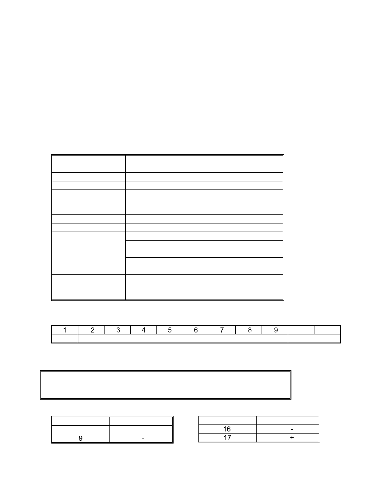
2.1 Communication Specifications
Item S pecification
Electrical specification Based on EIA RS-485
Transmit system 2-wire, semi-duplicate
Synchronizing system Asynchronous mode
Connection format 1 : N
Number connection
unit
Up to 255 units
Transmission distance 500m max
Transmission speed 2400 / 4800 / 9600 / 19200 selectable
Start bit 1 bit
Data length bit 8 bits
Parity bit None
Data format
Stop bit 2 bits
Transmission code HEX value (MODBUS RTU mode)
Error detection CRC-16 bits
Isolation Functional isolation between transmission circuit
and others (with stand voltage: 500V AC).
A typical MODBUS protocol character is shown below:
10 11
Start bit Data bits Stop bits
One character is including 1 Start bit and 8 Data bits and 2 Stop bits.
3. CONNECTION
△ WARNING
For avoiding electric shock and malfunctions, don’t turn on the power supply
until all wiring has been completed.
3.1 Terminal Allocation
SE2000 SET1 SET2
Terminal number Signal name
8 +
Terminal number Signal name

2
3.2 Wiring
Use twisted pair cables with shield.
Recommended cable: UL2464, UL2448, etc.
The total extension length of the cable is up to 500m. A master station and up to 255 units of
the SE series can be connected per line.
Both ends of the cable should be connecting with terminate resistors 100 1/2W.
The shield wire of the cable should be grounded at one place on the master station unit side.
4. SETTING OF COMMUNICATION CONDITION
In order that the master station and SE series can correctly communicate,
following settings are required.
All communication condition settings of the master station are the same as those of SE
series.
All SE series connected on a line are set to address (ADDR), which are different from each
other.
4.1 Set Items
The parameters to be set are shown in the following table. Set them by operating the front
panel keys.
Parameter Item Value at
delivery
Setting range Remarks
BAUD T ransmission
speed
9600
2400/4800/9600/19200
--------- Data length 8 bits
Fixed (can’t be changed)
--------- Stop bit 2 bit
Fixed (can’t be changed)
--------- Parity setting None
Fixed (can’t be changed)
Set the same
communication
condition to the
master station and all
slave station.
ADDR Address 1
1 to 255
Set a different value
to each station.
4.2 Setting Operation Method
The following example shows how to set the communication condition.
Example: Setting a transmission speed is 9600 bps and address at 12 on a station.
Key
operation
Indication Description
Power ON 25/100 Power on running state (PV/SP indication)
SET
(5 seconds)
PB
Press SET key simultaneously for approximately 5
seconds to get level parameter.
SET
(5 seconds)
TYPE
Press SET key simultaneously for approximately 5
seconds to get level parameter.
SET Press SET key to go into level.
SET ADDR Press SET key repeatedly until ADDR is display.
△ or ▽
ADDR/12
Press △ or ▽ key to setting “ADDR=12”
SET BAUD Press SET key again to select next parameter “BAUD”
△ or ▽
BAUD/9.6K
Press △ or ▽ key to setting “BAUD=9.6K”
 Loading...