

Gigaphone 20, 2432, 20-2432 User Manual

1
When using your telephone equipment, basic safety precautions should always
be followed to reduce the risk of fire, electric shock and injury, including the
following:
1. Read and understand all instructions.
2. Follow all warnings and instructions marked on the product.
3. Unplug this product from the wall outlet before cleaning. Do not use liquid
cleaners or aerosol cleaners. Use a damp cloth for cleaning.
4. Do not use this product near water (for example, near a bath tub, kitchen
sink, or swimming pool).
5. Do not place this product on an unstable cart, stand, or table. The product
may fall, causing serious damage to the product.
6. Slots and openings in the cabinet and the back or bottom are provided
for ventilation. To protect it from overheating, these openings must not
be blocked by placing the product on the bed, sofa, rug, or other similar
surface. This product should never be placed near or over a radiator or
heat register. This product should not be placed in a built-in installation
where proper ventilation is not provided.
7. This product should be operated only from the type of power source
indicated on the marking label. If you are not sure of the type of power
supply to your home, consult your dealer or local power company.
8 . Do not allow anything to rest on the power cord. Do not locate this product
where the cord will be abused by persons walking on it.
9. Never push objects of any kind into this product through cabinet slots as
they may touch dangerous voltage points or short out parts that could
result in a risk of fire or electric shock. Never spill liquid of any kind on
the product.
10. To reduce the risk of electric shock, do not disassemble this product.
Opening or removing cabinet parts other than specified access doors may
expose you to dangerous voltages or other risks. Incorrect reassembling
can cause electric shock when the appliance is subsequently used.
11. Do not overload wall outlets and extension cords as this can result in the
risk of fire or electric shock.
Important Safety Instructions

2
12. Unplug this product from the wall outlet and contact Sprint customer
support under the following conditions:
A. When the power supply cord or plug is damaged or frayed.
B. If liquid has been spilled into the product.
C. If the product has been exposed to rain or water.
D. If the product does not operate normally by following the operating
instructions. Adjust only those controls that are covered by the
operating instructions, because improper adjustment of other controls
may result in damage and will often require extensive work by a Sprint
authorized technician to restore the product to normal operation.
E. If the product has been dropped and the cabinet has been damaged.
F. If the product exhibits a distinct change in performance.
13
. Avoid using a telephone (other than a cordless type) during an electrical
storm. There may be a remote risk of electric shock from lighting.
14
. Do not use the telephone to report a gas leak in the vicinity of the leak.
SAVE THESE INSTRUCTIONS
3
The 20-2432 is an advanced cordless telephone that operates in the 2.4GHz
frequency range.
This manual is designed to familiarize you with the 20-2432 cordless
telephone. We strongly recommend you read the manual before using your
phone.
To order replacement batteries or accessory headsets, call your
nearest Bell South business office or visit one of our conveniently
located Retail Stores.
Introduction
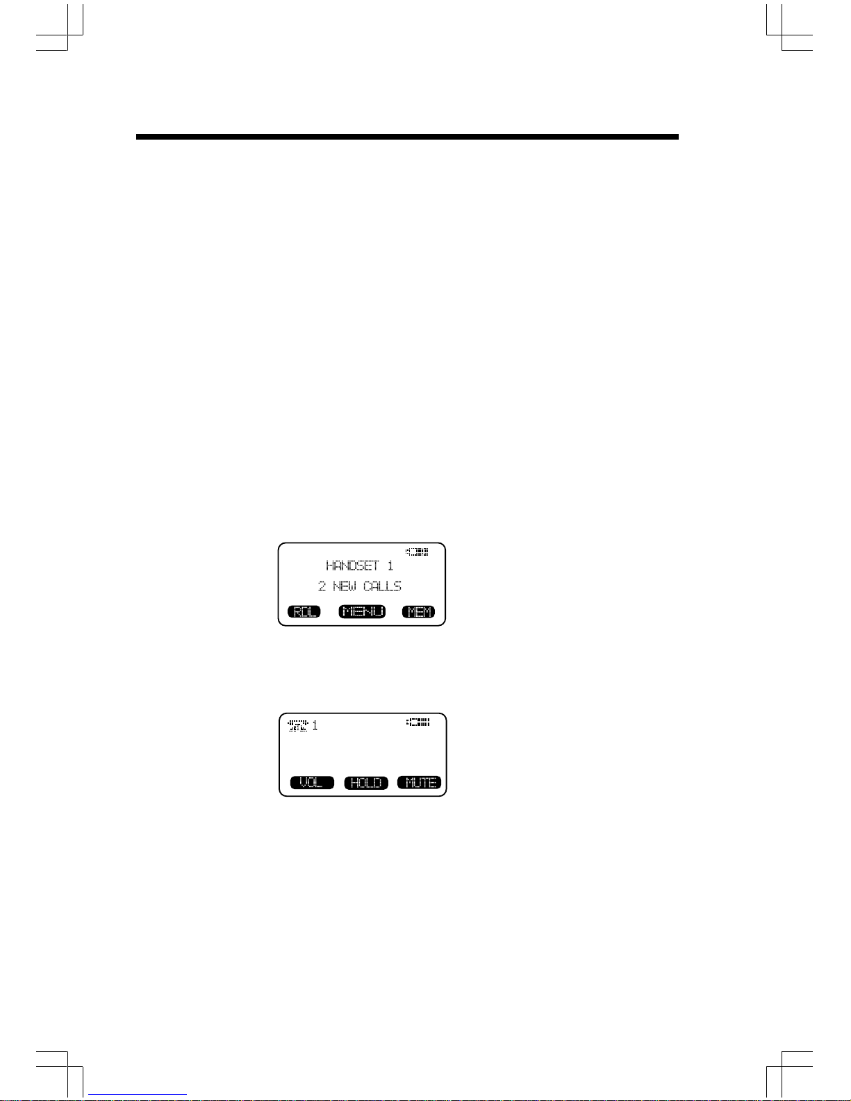
MENU DRIVEN DISPLAYS
The 20-2432 Handset and Base feature a user-friendly display, making it easy
to access the many features of this cordless system. The three black keys,
found directly below the LCD screen, are called soft keys. They are called
this because their functions change depending on what you're doing-making
a call, reviewing Caller ID, adding a name and number to your Phone Book,
etc.
For example, when the Handset is in the idle mode, the LCD displays:
In this case, the 3 soft keys access REDIAL, MENU and MEMORY.
When the Handset is active, the LCD displays:
In this case, the 3 soft keys access VOLUME, HOLD and MUTE.
4
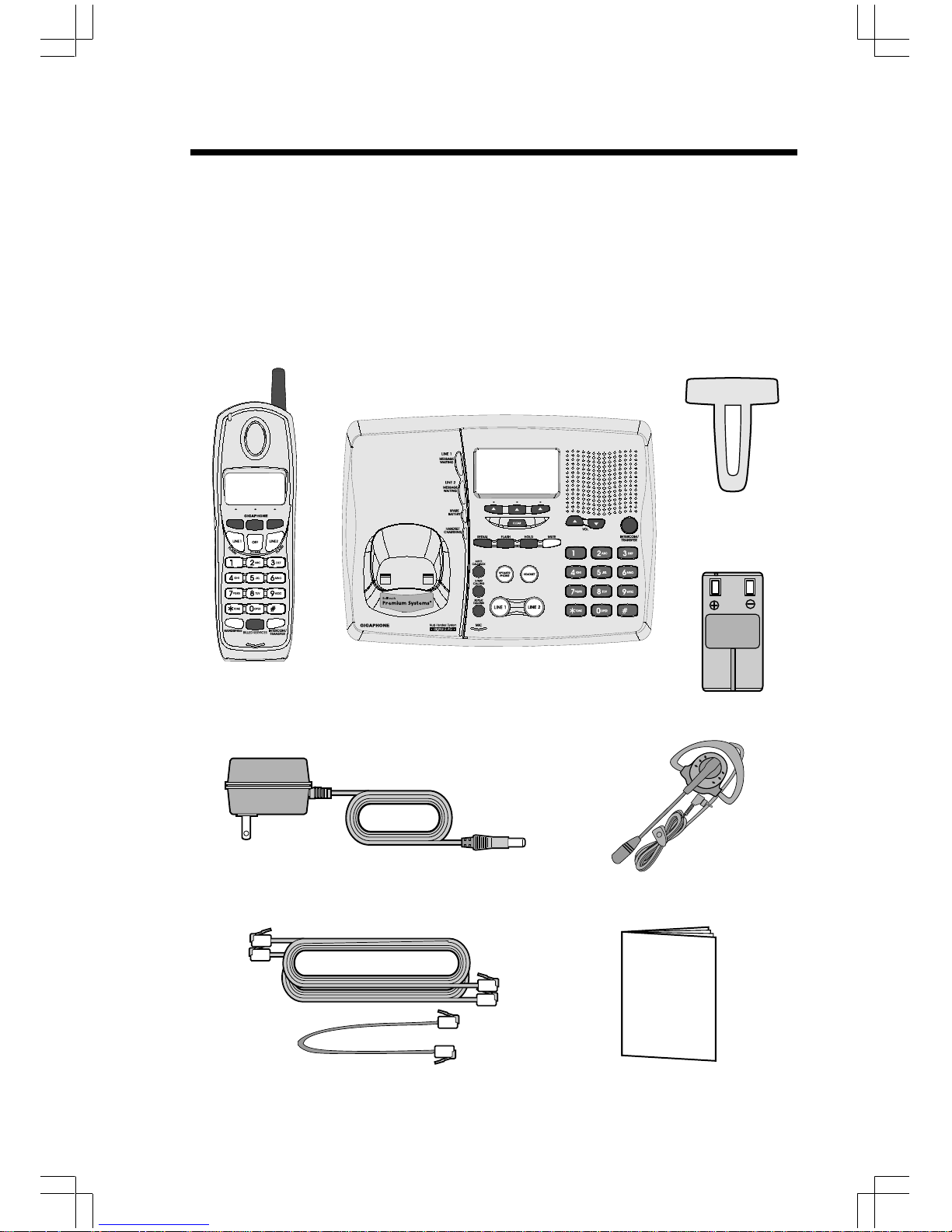
Parts Check List
5. Battery Pack (2)
6. Belt Clip
7. Owner's Manual
8. 2.5mm Headset
To purchase replacement battery packs, call Customer Service at 1-800733-2355.
1. Base Unit
2. Handset
3. AC Power Adapter
4. Telephone Cords
Telephone Line Cord
AC Power Adapter
Handset
Base Unit
Belt Clip
2.5mm Headset
Owner's Manual
OWNER'S MANUAL
Battery Pack x 2
5
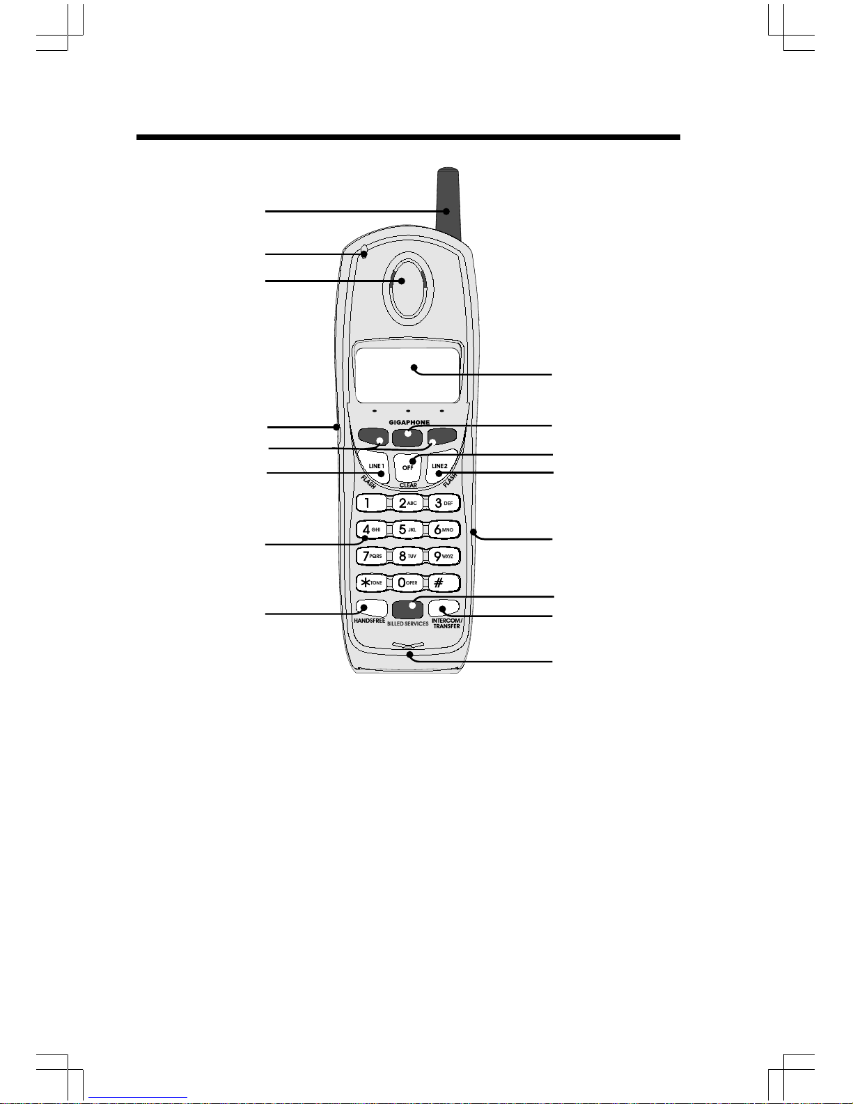
The Handset Layout
1. Antenna
2. Message Waiting Indicator
3. Earpiece
4. Headset Jack (2.5mm)
5 . Scroll Keys
6. Line 1 (Flash)
7. Dialing Keys (0-9,*,#)
8. Handsfree Speakerphone
9. LCD Display
10. Select/OK
11. Off (Clear)
1 2. Line 2 (Flash)
13. Battery Compartment(back
of Handset)
1 4. Billed Services Key
15. Intercom/Transfer Key
16 . Microphone
1
3
4
5
6
7
8
9
10
12
16
13
2
14
15
11
6
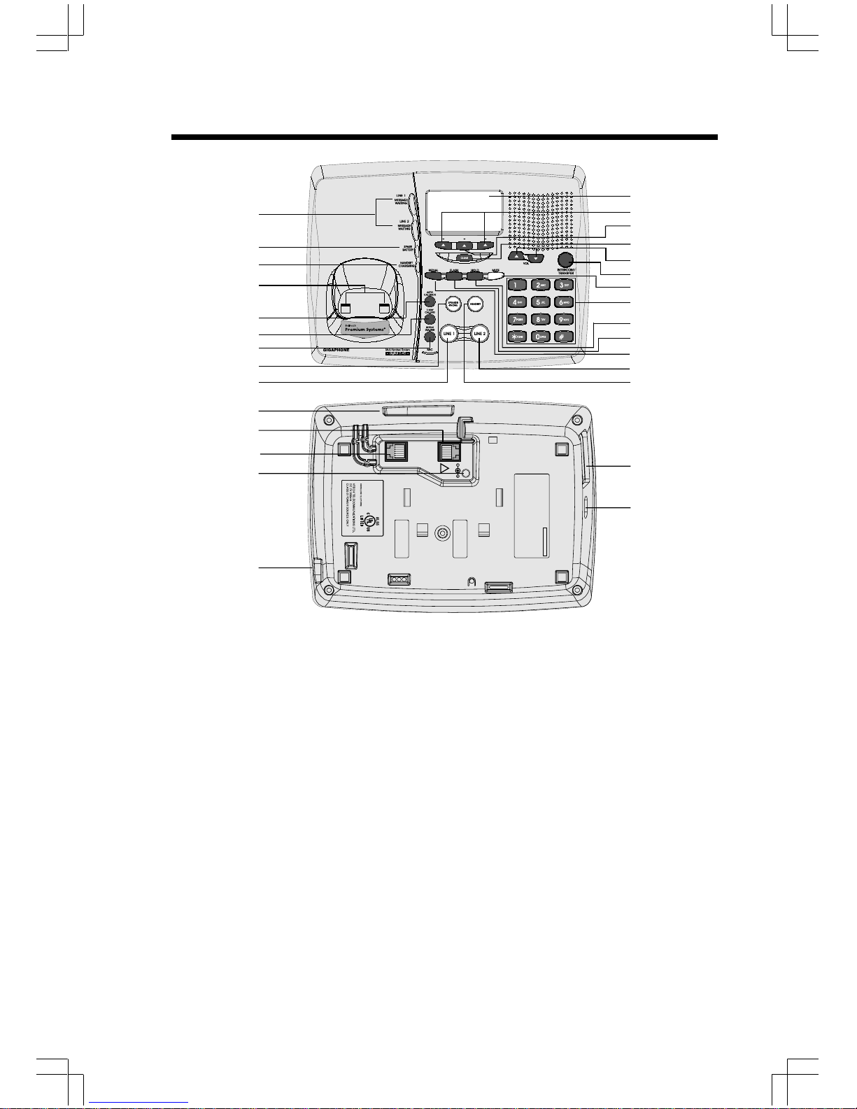
1 . Message Waiting Indicator
(Line1,Line2)
2. Spare Battery Indicator
3. Charge Indicator
4. Charging Contacts
5 . Auto Callback Key
6. 3-Way Calling Key
7. Repeat Dialing Key
8. Speakerphone Key
9. Line 1 Key
10. Data Jack
1 1. Line 1 Jack
1 2. Line 2 Jack
13. DC Connector
14. Headset Jack
15. LCD Display
16. Scroll Keys
17. Select Key
1 8. Clear Key
1 9 . Volume Keys
20. Intercom/Transfer Key
21. Mute Key
2 2. Dialing Keys (0-9,*,#)
23. Hold Key
24. Flash Key
25. Redial Key
26. Line 2 Key
2 7. Headset Key
2 8 . Spare Battery Drawer
29 . Spare Battery Release
The Base Unit Layout
1
16
17
8
9
4
5
18
20
19
21
22
23
24
25
2
3
15
26
27
6
7
LINE 2
LINE 1/
L1 + L2
7V DC
!
COMPLIES WITH 47 CFR PART 68
REGISTRATION NO.: US: EW7 WI00B80-513700
RINGER EQUIVALENCE: 0.0B
USOC JACK: RJ11C, RJ14C
THIS DEVICE COMPLIES WITH PART 15 OF THE FCC RULES. OPERATION
IS SUBJECT TO THE FOLLOWING TWO CONDITIONS: 1)THIS DEVICE MAY
NOT CAUSE HARMFUL INTERFERENCE; AND 2) THIS DEVICE MUST
ACCEPT ANY INTERFERENCE RECEIVED, INCLUDING INTERFERENCE
THAT MAY CAUSE UNDESIRED OPERATION.
PRIVACY OF COMMUNICATIONS MAY NOT BE ENSURED WHEN USING
THIS PHONE.
MODEL : 20-2432
VTECH TELECOMMUNICATIONS LTD.
MANUFACTURED IN CHINA
FCC ID: EW780-5001-00
HAC
12
13
14
11
10
28
29
7
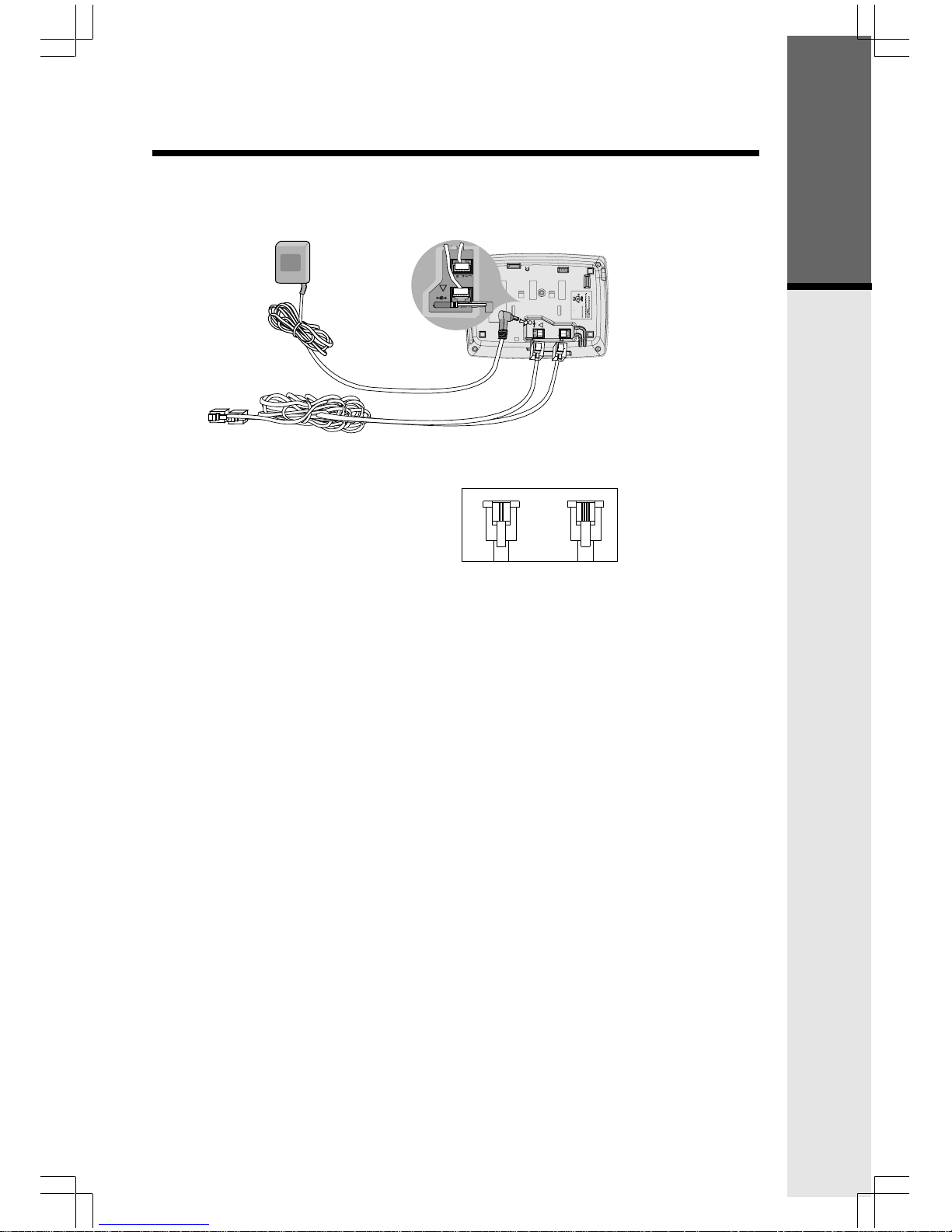
Setup
Plug the AC power adapter into an electrical outlet, and the DC connector
into the back of the base unit.
Connecting to the telephone lines
Your 2-Line 20-2432 will work fine even if you only have one telephone line.
We recommend connecting the modular telephone cord to the jack labeled
LINE 1 / L1 + L2, located on the bottom of the Base Unit. Here are steps for
connecting 2 lines:
If you have 2 Lines coming out of a Single Wall Jack:
Connect a 4-wire (RJ-14) modular phone cord between the wall jack and the
phone jack labeled L1 / L1 + L2.
If you have 2 Lines, each coming out of Separate Wall Jacks:
Connect a modular phone cord from the wall jack you want to designate as
your LINE 1, to the LINE 1 / L1 + L2 jack on the bottom of the Base Unit. Next,
connect a phone cord from the remaining wall jack to the LINE 2 jack on the
Base Unit.
Data Port
Your 2-Line 20-2432 has a Data Port on the back of the Base Unit. This port
provides an easy way to connect your fax machine, laptop computer, modem
or other telephone device for direct access to LINE 2.
The Data Port only provides access to Line 2, so you must have an active line
connected to the LINE 2 jack on the bottom of the Base Unit. Connect a
modular phone cord from the Data Port (look for the small door marked DATA
on the back of the Base Unit) to your fax, laptop, etc.
NOTE: While the Data Port is in use, accidental use of Line 2 by a parallel
phone, your 20-2432, or a Call Waiting ID alert may interrupt the data
transmission.
Getting Started
To AC outlet
To telephone
jack
To telephone
socket outlet
AC adapter
Examples of 1-Line and 2-Line Cords
RJ-11
One line
cord
RJ-14
2 line
cord
LINE 2
LINE 1/
L1 + L2
7V DC
!
COMPLIES WITH 47 CFR PART 68
REGISTRATION NO.: US: EW7 WI00B80-513700
RINGER EQUIVALENCE: 0.0B
USOC JACK: RJ11C, RJ14C
THIS DEVICE COMPLIES WITH PART 15 OF THE FCC RULES. OPERATION
IS SUBJECT TO THE FOLLOWING TWO CONDITIONS: 1)THIS DEVICE MAY
NOT CAUSE HARMFUL INTERFERENCE; AND 2) THIS DEVICE MUST
ACCEPT ANY INTERFERENCE RECEIVED, INCLUDING INTERFERENCE
THAT MAY CAUSE UNDESIRED OPERATION.
PRIVACY OF COMMUNICATIONS MAY NOT BE ENSURED WHEN USING
THIS PHONE.
MODEL : 20-2432
VTECH TELECOMMUNICATIONS LTD.
MANUFACTURED IN CHINA
FCC ID: EW780-5001-00
HAC
7V DC
!
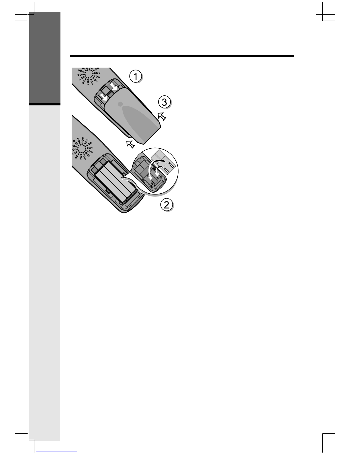
8
Follow the steps below:
1. Remove the battery cover by
pressing on the indent and
sliding downward.
2
. Place the new battery pack in the
handset with the metal contacts
aligned with the charge contacts
in the battery compartment.
3. Replace the battery cover by
sliding it upwards.
4
. If the new battery pack is not
already charged, place the
handset in the base unit, or a
remote charging stand, and allow
it to charge for 12 hours. After
initial charge, a maintenance
charge of 8 hours should be
sufficient.
Installation of Battery Pack in Handset
Getting Started
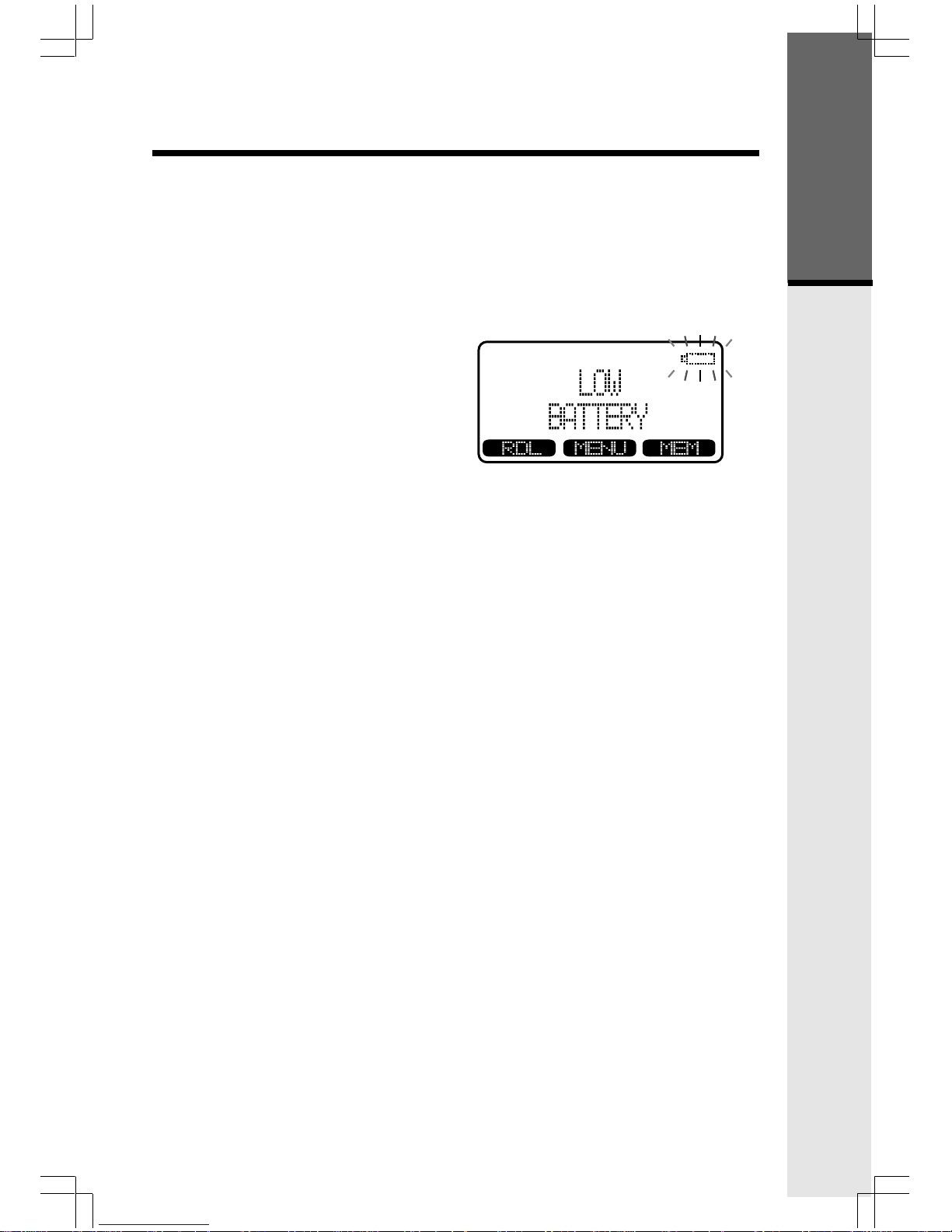
9
• The handset seems completely
dead, the LCD is completely
clear and does not activate when
you press the keys.
• The low battery message is
displayed :
Charging Of Handset Battery Pack
The Handset of your 20-2432 cordless telephone is powered by a rechargeable
battery pack. It charges automatically whenever the Handset is in the Base
Unit.
You should charge the battery pack for 12 hours when you first receive your
phone. You'll know the battery pack needs charging when:
IMPORTANT:
1. Do not dispose of a battery pack in a fire, the cell may explode.
2. Do not open or mutilate the battery pack. Toxic substances may be released,
causing harm to eyes or skin.
3. Exercise care in handling battery packs in order to prevent an accidental
short of the charge contacts, potentially causing the battery pack to
overheat.
4. Do not dispose of this battery pack into household garbage. Contact your
local recycling organization for recommended disposal sites.
Charging Of Handset Battery Pack
Getting Started

10
Checking for Dial Tone
After the battery is charged press a LINE key on the Handset. PHONE ON
will appear on the Handset display, and you will hear dial tone. If not, see
In Case of Difficulty.
Tone/Pulse Selection
See SELECT TONE/PULSE AT THE BASE UNIT for details.
CAUTION: Use only the power supply provided with your cordless phone.
IMPORTANT:
FOR MAXIMUM PERFORMANCE OF YOUR
CORDLESS TELEPHONE SYSTEM:
1. Choose a central location for your Base Unit.
2. Install your Base Unit and Extension Handsets
away from electronic equipment, such as personal
computers, television sets and microwave ovens.
3. In locations where there are multiple cordless
telephones, separate base units as much as possible.
4. Install your telephone equipment away from heat
sources and sunlight.
5. Avoid excessive moisture, dust or extreme cold.
Dial Tone
Getting Started
BEFORE USING YOUR HANDSET CAREFULLY PEEL OFF THE
PROTECTIVE FILM COVERING THE DISPLAY.
11
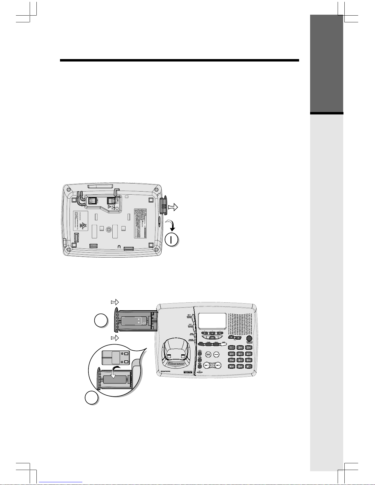
Spare Battery Charger/Power Backup Function
The 20-2432 uses the spare battery charger in the Base Unit to provide
operational backup in the event of a power failure. With a fully charged battery
pack in the spare battery charger, you will still be able to place and receive
calls from the Handset for up to one hour. During Power Backup mode, you
will not be able to use the Base Unit.
The spare battery pack can also be used to replace a drained handset battery,
ensuring uninterrupted use.
NOTE :
When using the 20-2432 during Power Backup mode, audio quality may be
compromised due to reduced power availability.
1. Open the spare battery charger
by pressing the release button,
located on the left-hand side of
the Base Unit. A drawer will
open to reveal the spare battery
compartment.
2. Place a battery pack in the
drawer with the charge contacts
facing up and to the right.
3. Push the drawer closed.
The spare battery takes 24 hours to
fully charge a drained battery.
Getting Started
2
3
CAUTION: TO
REDUCE RISK OF FIRE,
USE ONLY VTECH
80-5017-00-00
CAUTION: TO
REDUCE RISK OF FIRE,
USE ONLY VTECH
80-5017-00-00
BATTERY
INSTALL
THIS
SIDE UP
12
2
1
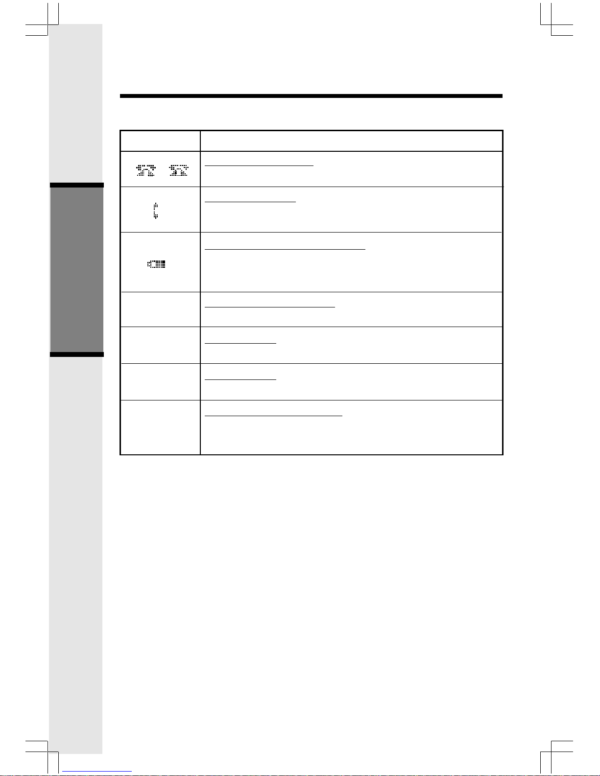
Basic Operation
Handset and Base Icons
Icon
Description
Line In Use indicator
On steady when the Handset is in use.
Intercom indicator
On steady when the Base and the Handset are in intercom
mode.
Battery indicator (Handset only)
Cycles (Low, Medium, and High) when Handset battery is
charging.
Flashes when a low battery condition is detected.
Enhanced Mode indicator
On steady when active Handset or Base is in Enhanced mode.
Mute indicator
On steady when the Handset or Base microphone is muted.
Hold indicator
On steady when the line is on hold.
AC Power Failure indicator
On steady when the AC power fails, the spare battery in
the Base Unit is providing power backup.
M
H
Handset and Base Indicators
E
P

13
Basic Operation
Handset LEDs
Message
Waiting
Base LEDs
LED
Line 1Message
Waiting/Line 2
Message Waiting
Line 1
Line 2
Handset
Charging
Mute
Speakerphone
Description
• Flash to indicate that you have new messages in your
voicemail. Service must be subscribed to through your local
telephone company.
Description
• Flashes to indicate that you have new messages in your
voicemail. Service must be subscribed to through your local
telephone company.
• Lights when line is being used by the
20-2432 system.
• Flashes when another telephone on the same line (parallel
extension) is in use or when line is on hold.
• Lights whenever the Handset is placed in the Base Unit
charging cradle.
• Lights when Base microphone is muted.
• Lights when Base Speakerphone is in use.
• Lights when a Spare Battery pack is charging in the Base
Unit charger.
Spare Battery
Headset
• Lights when the Headset option is in use on the Base
Unit.
Handset and Base Indicators
LED
14
Basic Operation
The 20-2432 has an advanced design
that uses a menu structure and soft
keys to access all of the built-in
features.
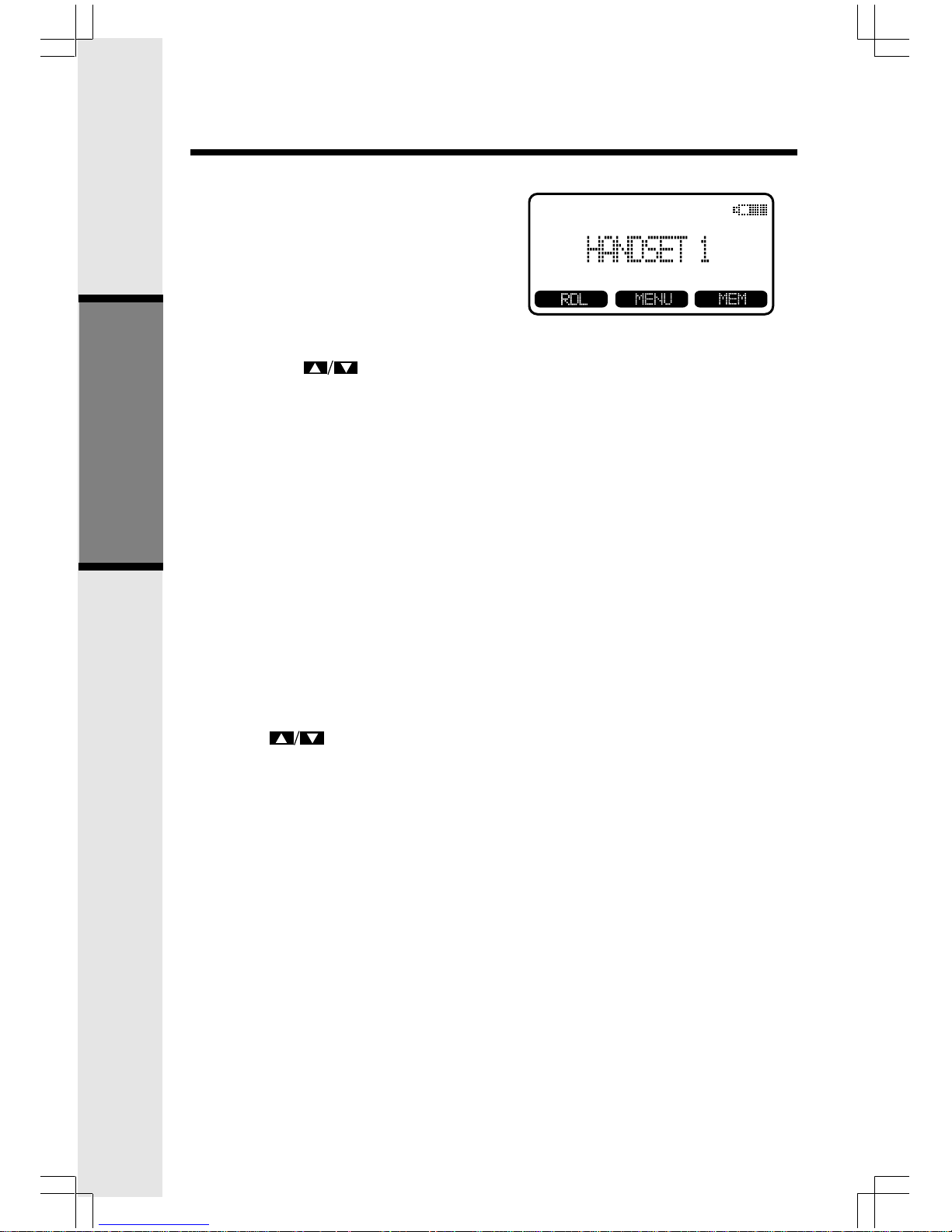
Example of the idle mode display:
Soft Menu Functions
RDL (Redial)
Press RDL to display the last 5 telephone numbers dialed. The number on
the top line is the most recent number dialed.
• Use the scroll keys to select the desired the number.
• To dial the number, you can simply press a LINE or the HANDSFREE
key.
• You can erase a redial number by scrolling until it is highlighted, then
press SELECT, and then ERASE.
• You can save a redial number to phone book memory by scrolling until
it is highlighted, then press SELECT, and then press SAVE. Then add
a name to your entry by following the instructions under To Store a
Number/Name.
HANDSET MENU
With the Handset in the idle (OFF) mode, press the MENU key to access
the following options:
• CALL HISTORY (Caller ID)
• HANDSET SETTINGS
Use the scroll keys to select the desired option, then press OK.
Press the OFF/CLEAR key to step back through the menu structure. Press and
hold the OFF/CLEAR key to return to the idle menu.
BASE UNIT MENU
With the Base Unit in the idle (OFF) mode, press the MENU key to access the
following options:
• CALL HISTORY (Caller ID)
• SETUP BASE
Press the CLEAR key to step back through the menu structure. Press and
hold the CLEAR key to immediately return to the idle menu.
 Loading...