

Gigant Lift Column Series Installation Instructions Manual
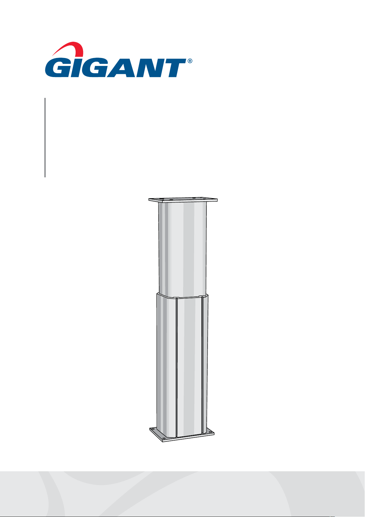
Lift Column
Installation instructions
Description
Installation instructions
Areas of application
Gigant lift columns are supposed to be built in and used to
adjust the working position of workstations, f xtures or other
machines. Other areas of application can be dangerous, so
instructions from Gigant must be carefully studied and followed.
• Lift columns should not be used during hot work
such as welding without specif c precautions being
taken
• Lift columns must not be suspended from a
ceiling or walls
• Lift columns must not be used to lift people
!
Attention
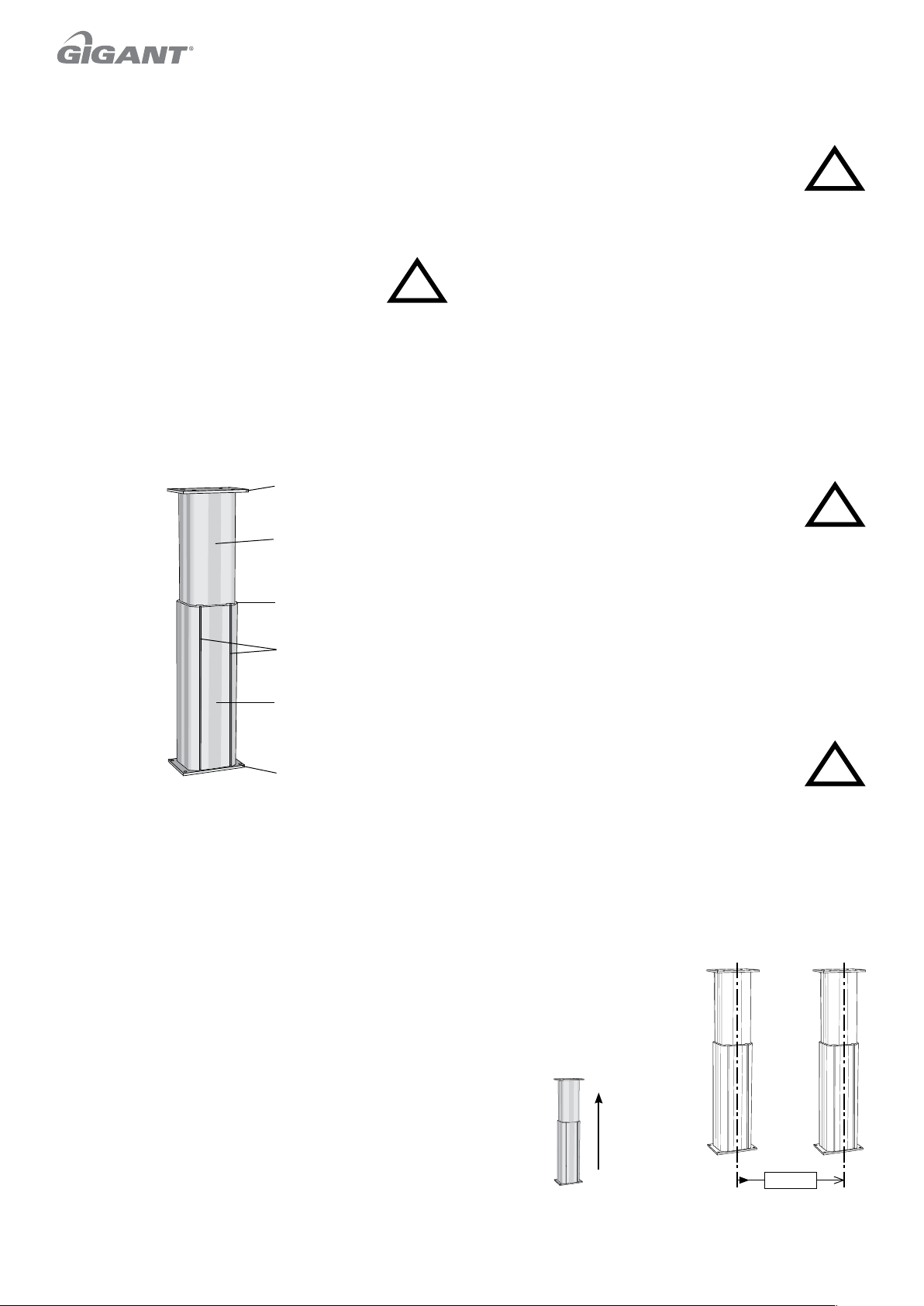
Design
T e image to the right shows the lift column’s various
components.
Top plate
Inner tube
Inaccurate handling can cause malfunction. Please
make sure that all the steps in this assembly
instruction always are implemented in order to
ensure correct and safe function of the product.
• Compare the specif cations of the product with your current
application. Only when your specif cations are within the
products specif ed range can the product be used.
• Follow local laws and regulations
• Use the product in its original design without any changes.
!
Attention
Transport damage
Inspect the goods as soon as they arrive and report any transport
damage direct to the forwarder.
Transport/handling
Storage: time in original packaging should be kept short. Keep in
a cool dry place, protected from light and dust.
Transport: depending on design the lift columns can
weigh 30 kg or more. Crush hazard: should the
product tip over it can cause crush injuries. Suitable
lifting equipment should be used to ensure safe
handling of the product during transport and assembly.
!
Risk of
crushing
Cover strip
Nut slot
(LP192, LP200)
Outer tube
Base plate
Function
T e lift function of the lift column is driven by an electric
actuator housed inside the telescopic element. T e actuator is
powered by a low voltage transmitted via an external power
source/control unit and regulated by a controller. Integrated limit
switches stop the column at its top and bottom positions.
An integrated Hall ef ect sensor (all lift columns with an 8-pin
connector) measures and compares pulses between two lift
columns in order to synchronize them and achieve precise
parallel operation.
Accessories
Examples of accessories from the Gigant range:
• Control unit for single or parallel operation with one or more
motor groups
• Control unit bracket for attaching control units to the outer
tube’s nut slots (LP192, LP200)
• Controllers, such as table or hand control, foot pedal
• Reinforced base for f oor installation
• Base frames with adjustable feet for freestanding installation
Assembly
• Gigant lift columns must be installed indoors in well-lit
premises that are at room temperature.
• Ensure that the lift column is level by assembling it on a stable
surface. For freestanding applications, base frames are available
as an accessory. Control units and controllers must be
positioned to avoid damage during operation.
• Gigant lift columns must be positioned at least
120 mm from walls or surrounding objects to avoid
the risk of crushing. Ensure that there is no contact
with surrounding objects and no risk of crushing
as the lift column is raised and lowered.
• When installing mechanically-linked lift columns for parallel
operation, the columns must be assembled so that any
deviation in parallelism is less than 0.5 mm per 1,000 mm.
If this is not possible, one or more attachments must be
f exible enough to absorb deviations.
• All Gigant lift columns are to be assembled with the inner
tube positioned upwards as shown in the
accompanying illustration if not
otherwise specif ed.
Up
// Ø 0,5
!
Risk of
crushing
 Loading...