

Page 1
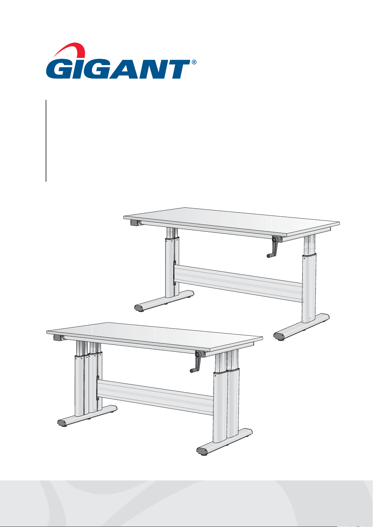
Flex 150/300
Worktable – Operating instructions
Page 2
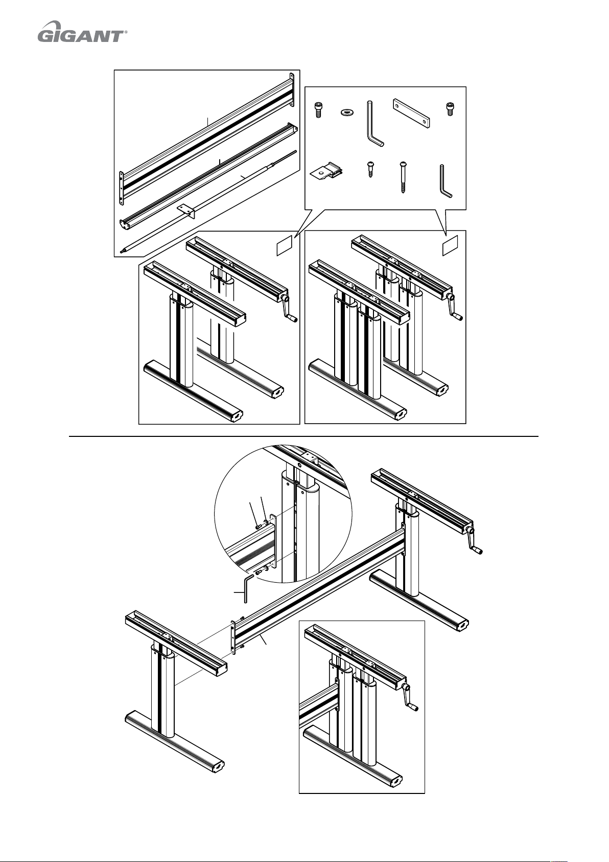
D E F G H
A
2x
1x
4x 4x
B
C
I J
6x 8x
4x
K L
12x
8x
1x
1
Flex 150
Flex 300
IDC 3040IDC 3020
E
D
F
A
Flex 300
IDC 3040
2
Page 3
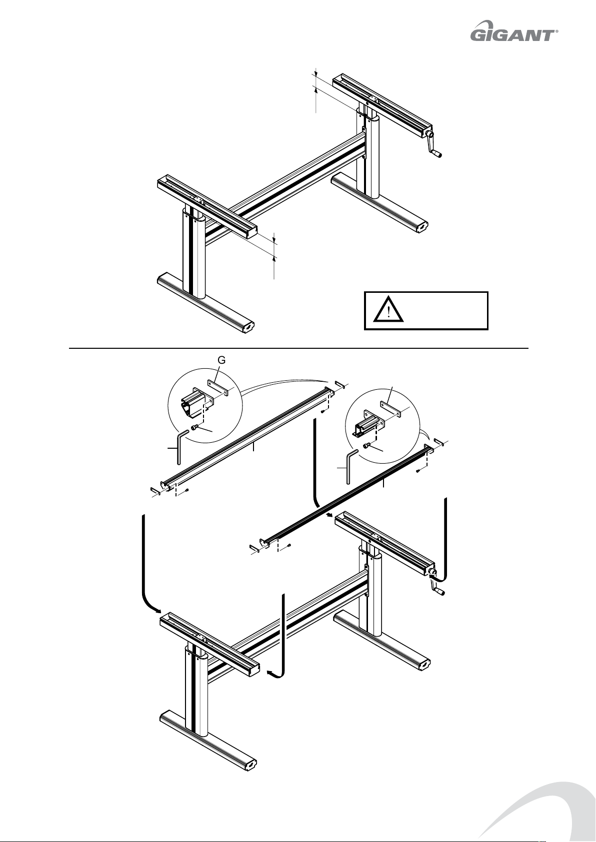
2
G
h2
h1
h1 = h2
3
G
H
F
B
F
H
B
3
Page 4
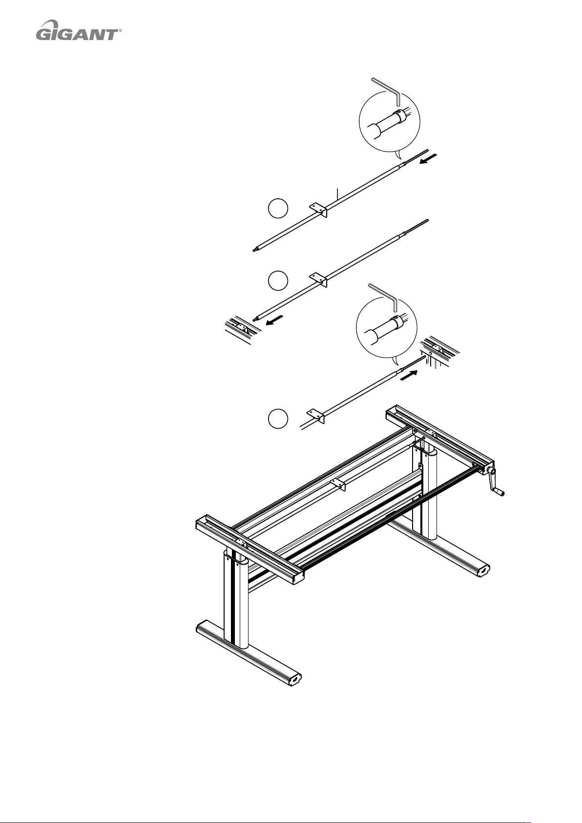
4
L
C
1
2
3
L
4
Page 5
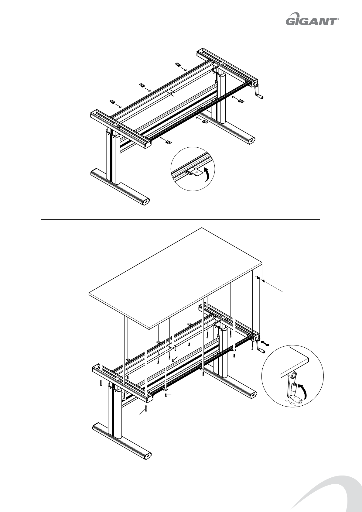
5
6
I
6x
K
12x
55 mm
J
J
5
Page 6
Installation instructions
Bordsskiva
• Place the table at least 120 mm from other objects, eg,
adjoining tables, equipment, wall mounted shelves, etc to
avoid trap hazard.
• Make the top of the table level, ie, with the aid of the
adjustable feet on the frame.
• Test run the table and ensure that the drive axle works on
both sides.
Additional safety devices must be mounted in accordance with
instructions from Gigant if the table is to be placed in series.
When moving the table, never lift it by the top of the table
because the frame is too heavy.
Description
T e table is made for indoor use in an industrial or of ce
environment.
Conf guration
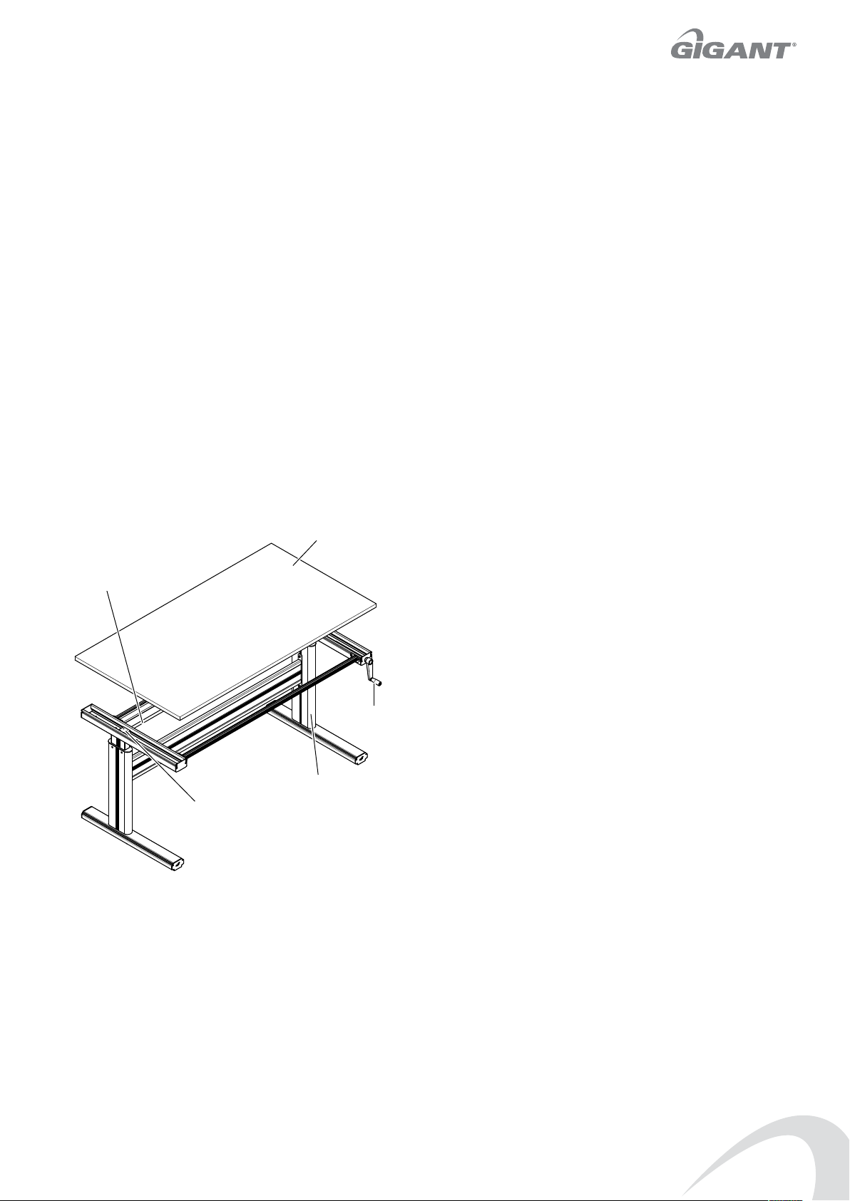
T e f gure shows the main parts of the table. T e table should be
completed with a suitable tapletop from Gigant:s product range.
Table top
Accessories
Accessories that are approved by Gigant for tables Flex 150 and
Flex 300 include the following:
• Set of wheels.
• Drawer and drawer suspension.
• Extensionframe for extensions.
• Tiltable tabletop.
• Undershelf.
Operating instruction
Raising and lowering the table
• Ensure that the table top, and anything placed on the table,
has clearance in relation to surrounding objects.
• Pull the crank forward so that it is clear of the table top.
• Crank to the desired height and then push the crank back
under the table top.
NB! When the table height is adjusted in right position, the table
has to be locked by pushing the crank under the table top.
WAr n In g !
Observe the danger of crushing between the table top or frame
and adjoining equipment when raising and lowering.
T e danger of tipping must be considered if load protrudes
beyond the extent of the frame.
Drivaxel
Drive axle
Crank
Vev
Teleskopben
Telescopic leg
Gear wheel between drive axle
Kuggväxel mellan drivaxel
och trapets gängad skruv
and buttress threaded screw
Function
T e lifting function of the table is achieved by a crank that
transfers force via a gear wheel to the drive axle. T e drive axle in
turn is connected via gear wheels to a buttress threaded screw in
each of the telescopic legs.
Glide plates f tted in each telescopic leg ensure smooth and even
lifting action.
T e crank can be pushed in under the table top when not in use.
For tables with a top that can be sloped:
WAr n In g !
Observe the danger of crushing if the table is f tted with an
adjustable sloping top.
Caution. T e top may not be sloped when loose objects are on
the table since this could otherwise result in personal injury.
Maintenance
All moving parts are lubricated at the factory and are therefore
free from maintenance.
Page 7

www.gigant.co.uk
 Loading...