


Version
E 141203
Users Guide
P - 9710 series
Optometer
P - 9710 - 1, P - 9710 - 2, and P - 9710 - 4
Measurement and examination devices for optical radiation detectors
Gigahertz-Optik GmbH
An der Kaelberweide 12,
D-82299 Tuerkenfeld.
Telephone +49 8193 93700 - 0
Telefax +49 8193 93700 - 50
info@gigahertz-optik.de
www.gigahertz-optik.de
Gigahertz-Optik Inc.
5 Perry Way
Newburyport MA 01950-4009 USA
Telephone:+ 978 462 1818
Telefax: + 978 462 3677
Email: b.angelo@gigahertz-optik.com
Website: www.gigahertz-optik.de
Page 1

Table of contents:
1. Additional information to the operating instructions
1.1 Safety precautions
1.2 Hazard clause
1.3 Liability
1.4 Safety
1.5 Environmental conditions
1.6 Maintenance and cleaning
1.7 Guarantee
1.8 CE Conformity declaration
1.9 Review clause
1.10 Contact details
2. Device description P - 9710 optometer
2.1 Intended use
2.2 Inspection
2.3 Technical specifications P - 9710 series
2.4 Additional technical specifications P - 9710
variants
2.4.1 Optometer P - 9710 - 1
2.4.2 Optometer P - 9710 - 2
2.4.3 Optometer P - 9710 - 4
2.5 Description of the measurement ranges
2.6 Device overview
2.7 Detector interface
2.8 RS232 Interface / Analog Output
2.9 Trigger input (device variant P - 9710 - 4 only)
3. Performing measurements
3.1 Version Info
3.2 Quick start guide
3.3 P - 9710 Menu Structure
3.3.1 General information
3.3.2 Menu Overview
3.3.3 Front panel buttons
3.3.4 Menu description “Mode”
3.3.5 Menu description “Range”
3.3.6 Menu description “Detector”
3.3.7 Menu description “Offset”
3.3.8 Menu description “Reference”
3.3.9 Menu description “Substitution”
3.3.10 Menu description “Setup”
3.3.11 Menu description “Info”
3.4 Remote Interface (RS232)
Page
4
4
4
5
5
5
6
6
6
6
7
8
8
8
9
10
10
10
10
11
12
13
14
14
15
15
15
15
15
16
20
20
23
23
23
23
24
24
26
27
Page 2

4. Accessories
5. Maintenance and services
5.1 Battery
5.2 Calibration
5.3 Service addresses
A. Appendix - Measurement Modes
A.1 I-Effective
A.1.1 I-Effective (Schmidt - Clausen, SC)
A.1.2 I-Effective (Blondel - Rey, BR)
A.2 Relative Logarithmic
A.3 Pulse Energy
A.3.1 Principle
A.3.2 Pulse Energy Measurement
28
29
29
29
30
31
31
31
32
33
33
33
34
Page 3

Additional information to the operating instructions
1
1.1 Safety precautions
Please read this users guide carefully before using the device! Trouble-free
functioning of the device as well as the operational safety can only be guaranteed when the safety precautions and the general safety measures described in this users guide are considered.
The device should only be used for its intended purpose and according to
its technical specifications. Any other use of the device is not allowed.
Immediately after unpacking and before the device start-up, the device
should be inspected for any mechanical damages or loose parts. In such
cases, the device should not be used.
Safety can also be impaired if the device is not functioning properly.
If during operation it is suspected that the safety has been impaired, the
device should be switched off and its use by third parties ruled out.
1.2 Hazard clause
The device described in this instruction manual is designed for optical radiation measurements. The device offers no protection against radiation risks
affiliated with the measured objects.
Persons in charge of performing measurements and using the device are
obligated to read and comply with the instructions given in this users guide
before beginning any measurement.
Persons in charge of performing measurements and using the device must
be well informed about accident prevention regulations in their field of work.
Handling the device requires intermittent concentration of the operator on
the device. The device should therefore not be used in surroundings that
might lead to interrupted operator attentiveness. This possible risk must
also be included in the briefing of the device operator.
Through this users guide, Gigahertz-Optik GmbH as the device manufacturer informs the device owner about the possible hazards while using the
device. The owner and the responsible device users confirm the receipt
and approval of this users guide. The owner and operator of the device
have been informed about the diligence required when choosing and briefing the device users and operators.
1.3 Liability
The responsibility for all consequences that might arise from the use of the
measurement device or its accessories lies solely on the user and/or owner.
Page 4

Gigahertz-Optik GmbH or its suppliers can under no circumstances be liable for any direct or indirect business interruptions, loss of profits or data
loss. This also applies to damages that may arise during the device operation.
The Gigahertz-Optik GmbH Terms and Conditions of Delivery and Payment generally apply.
1.4 Safety
The measurement device is designed for operation in a clean environment
and within operating temperatures ranging from +5 to +40 ºC.
The measurement device or its accessories are not to be exposed to direct
sunlight or moisture.
The device should be switched off and secured against unintended start-up
by third parties in case of indications suggesting unsafe operating conditions. Such indicators include:
when the device shows visible damages
when the device contains lose parts, either internal or external
when the device is not functional
Safe operation of the device can be impaired due to one of the following
circumstances:
Outdoor storage or storage in moist environment over a long period of
time or other adverse conditions.
Excessive strain during transport (e.g., due to improper packaging)
Operation in aggravated environmental conditions such as high temperatures, humidity, etc.
Operation in dangerous conditions (explosive gas, fumes, dust, etc.)
1.5 Environmental conditions
Optical measurement devices are sensitive to influences resulting from
certain environmental conditions, e.g., high temperatures, humidity, and
contamination, which might lead to measurement errors!
The measurement device should not be taken from a cold environment and
directly put to operation in a warm surrounding. Under certain circumstances, condensation could arise and negatively impact on the electrical and
optical functions. Allow the device to adjust to the temperature of the surroundings before switching it on.
The measurement device should not be operated within high magnetic,
electromagnetic or electrostatic fields.
Page 5

1.6 Maintenance and cleaning
The intervals for the recurrent recalibrations should be observed!
Opening of the device as well as device repair should only be done by authorized persons.
Off-the-shelf, residue-free, and non-abrasive detergents can be used for
the exterior cleaning of the device.
While cleaning it should be made sure that the detergent doesn’t penetrate
the interior of the device. This can lead to short circuiting or device operation errors.
Do not use aggressive cleaning agents.
1.7 Guarantee
Gigahertz-Optik GmbH warrants that the product is free from material and
production defects for a period of 12 months beginning from the date of
delivery. In case defects are experienced within the warranty period, Gigahertz-Optik GmbH repairs or replaces the device free of charge.
In order for the warranty to be effective, the customer should submit the
product name, serial number, date of purchase as well as the description of
the defect in writing to Gigahertz-Optik GmbH after which he/she will receive a service number (RMA) enabling him/her to send back the device.
The user is responsible for the appropriate packaging of the device.
Shipping through the user must be done on a free to buyer’s address basis.
The guarantee does not cover consequential damages.
The Gigahertz-Optik GmbH Terms and Conditions of Delivery and Payment generally apply.
1.8 CE Conformity
Gigahertz-Optik GmbH declares that the measurement device, with regards to its design and conception, conforms to the EG-guidelines and
corresponding harmonized norms.
The CE Declaration of Conformity can be requested separately.
If any alteration is made on this machine without prior agreement
this declaration loses its validity.
1.9 Review clause
Gigahertz-Optik GmbH reserves the right to changes in this users guide
without prior notice.
Page 6

1.10 Contact details
Headquarters
Gigahertz-Optik GmbH
Kaelberweide 12
D-82299 Tuerkenfeld
Telephone: +49 (0) 8193 93700 - 0
Telefax: +49 (0) 8193 93700 - 50
Email: info@gigahertz-optik.de
Website: http://www.gigahertz-optik.de
North and South America
Gigahertz-Optik Inc.
5 Perry Way
Newburyport MA 01950-4009
USA
Telephone: + 978 462 1818
Telefax: + 978 462 3677
Email: b.angelo@gigahertz-optik.com
Website: http://www.gigahertz-optik.com
Page 7

2 Device description P - 9710 optometer
2.1 Intended use
The P - 9710 optometers are measurement and examination devices for
optical radiation detectors.
The device can be controlled manually via front panel buttons or via a
RS232 remote interface.
Measurement results are displayed on the integrated display (LCD) or
transmitted via the RS232 remote interface.
Different optical quantities or wavelength bands can be measured by using
different detector heads in combination with the P - 9710 devices.
The calibration of the optical quantities is stored in the connector plug of
the detector head. This allows using different detector heads with the P 9710 device or using the detector heads with different P - 9710 devices
without the need to change or transfer calibration factors manually.
The P - 9710 devices have built-in batteries that are charged with the supplied plug-in power supply. The capacity of the battery allows
5 hours of
operation with display illumination on and 12 hours with illumination off.
2.2 Inspection
Upon receiving your device, please check the package and all its parts for
any possible damages that may have occurred during transportation.
Any transport damages should immediately be reported to the shipper.
After unpacking, please check to confirm there are no transport damages
or any irregularities with regards to package completeness and correctness. The scope of delivery contains:
one measurement device P - 9710
one power supply
a factory calibration certificate
this users guide
one hard-top casing (optional)
one serial interface cable (optional)
different measurement heads and their calibration certificate (optional)
Page 8

2 Device description P - 9710 optometer
2.3 Technical specifications P - 9710 series
Power supply
Display
Detector interface
Analog output
Units of measurement
Signal amplifier
CW integration time
Pulse integration time
Offset correction
built-in lead acid battery, 6V / 0.5Ah (Version before
2017)
Built-in lithium Ion battery, 3.7V /1400mAh (Version
2017)
operating time: 5hr / 12hr with backlight on /off
plug 5.5mm/2.5mm/9.5mm for external power
supply (7.5VDC - 8.0VDC / min. 250mA)
alphanumeric LCD, 2 rows x 16 chars
character height 5mm
LED backlight (on / off)
9pin DSUB (female)
output voltage proportional to detector input current
connector: TRIAD01 5pin (Tyco)
Amperes (absolute calibration)
optical units corresponding to calibration data
ratio in percent, logarithmic, and as factor
Transimpedance amplifier
8 ranges (200pA to 2mA)
fixed range or autorange
100µs - 5.9999s
10ms - 199.99s
correction range transcending
Parameter adjustment
Optical calibration data
Data logger
Front panel control
Remote interface
front panel keys or remote control
adjusted values permanently stored in EEPROM
10 different overall settings can be stored
stored in detector head connector (EEPROM)
max. 250 calibration table entries
interpolation between wavelength points possible
manual input of a calibration factor possible
max. 12288 entries, permanently stored in flash
memory
10 buttons, menu system
RS232 (9600 Baud, 8 Data Bits, 1 Stop Bit, No
Parity)
Connector: TRIAD01 (Tyco)
Page 9

2 Device description P - 9710 optometer
Temperature range
Size / weight
RoHS
2.4 Additional technical specifications P - 9710 variants
2.4.1 Optometer P - 9710 - 1
Amplifier slew rate
2.4.2 Optometer P - 9710 - 2
Amplifier slew rate
2.4.3 Optometer P - 9710 - 4
Amplifier slew rate
Trigger input
operating: 5°C to 40°C
storage: -10°C to 50° C
195mm x 100mm x 40mm / 500g
compatible
2ms - 10ms
20ms
20ms
starts pulse energy measurement
BNC (female)
low active
internal pull-up (22 kOhm to +5V)
Page 10

2 Device description P - 9710 optometer
2.5 Description of the measurement ranges
Page 11
2 Device description P - 9710 optometer
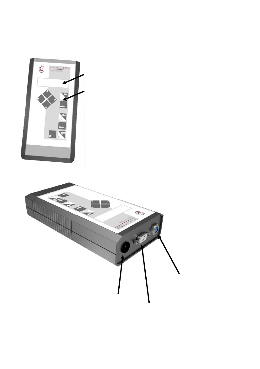
2.6 Device overview
P - 9710
Display
Front panel with 10 buttons
Page 12
RS232 interface / analog
output
plug for power supply
detector interface

2 Device description P - 9710 optometer
trigger input
(device variant P - 9710 - 4 only)
2.7 Detector interface
DSUB 9 pin
(female)
1 input current
2 GND
3 connection detection (GND by external detector)
4 GND
5 SCL (I2C, EEPROM)
6 GND
7 GND
8 +5V Output (Ri = 100 Ohm)
9 SDA (I2C, EEPROM)
function
Page 13

1
2
3 4 5
2 Device description P - 9710 optometer
2.8 RS232 Interface / Analog Output
Pin (TRIAD01
function
female)
1 Analog out (Ri = 10 kOhm)
2 TXD (has to be connected to RXD of PC)
3 RXD (has to be connected to TXD of PC)
4 GND
5 GND
View of the female connecter at P-9710
(Type TRIAD01 5pin /Tyco)
2.9 Trigger input (device variant P - 9710 - 4 only)
BNC (female) function
inner conductor trigger input, low active, internal pull-up (22 kOhm to +5V)
outer conductor GND
Page 14

3 Performing measurements
3.1 Version Info
The following information is related to P - 9710 Firmware Version V5.1.
3.2 Quick start guide
connect the plug-in power supply to the P - 9710 or use the internal battery
power
connect the detector head to the P - 9710
press <on/light> button to switch on the P - 9710
first the P - 9710 displays the Firmware Version: “P-9710 Vx.x”.
next the P - 9710 displays "Detector connected" and the detector’s serial
number
the meter/detector should now be set-up to default settings, i.e., without
further programming measurements can be performed
if necessary the P - 9710 measurement parameters can be reset to the
factory default values:
- press the <menu> button
- press <▲> up or <▼> down buttons until "Setup" is displayed, press
<enter> button to select
- press <▲> or <▼> buttons choose until "Configuration" is displayed,
press <enter> button to select
- press <▲> or <▼> buttons until "Default Init" is displayed, press <enter>
button to select
- P - 9710 asks for confirmation: "Change Data?", press <enter> button to
confirm or < esc / reset > to abort
now specific measurement parameters can be selected to perform a certain
measurement task (see "4.3 P - 9710 Menu Structure") as required
3.3 P - 9710 Menu Structure
3.3.1 General information
The P - 9710 can be manually operated and set-up for measurements using
the front panel keypad (10 buttons).
Pressing the <menu> button selects the main menu. There are further submenus. The up <▲> and down <▼> arrow buttons are used to switch between the different menus. By pressing the <enter> button the menu item displayed is selected. By pressing the <esc / reset> button one can escape from
the menu without changing parameters. Upon selecting a setting, the P - 9710
requests confirmation (“Change Data?”) to change the parameter. Press the
<enter> button to confirm that you really want to change the setting.
Page 15

3 Performing measurements
Use the <►> right and <◄> left arrow buttons to select the digit position
when changing numbers. The selected digit can be changed by using the
<▲> and <▼> arrow buttons. This also applies to the sign. Pressing the
<enter> button selects the adjusted number.
3.3.2 Menu Overview
The following table is a quick reference guide to the different menu items /
functions available in the P - 9710.
menu item submenu item function
1. Mode CW displays the measurement respective of
any offset and calibration factors programmed
CW Maximum displays the highest detected reading
CW Minimum displays the lowest detected reading
Peak Maximum shows the maximum detected peak level
Peak Minimum displays the minimum detected peak level
Peak to Peak displays the difference between the de-
tected peak maximum and peak minimum
level
I displays the measurment result regarding
the distance between light source and
detector as luminious intensity / radiant
intensity
I-Effective (SC) enables the measurement of pulsed light
signals with evaluation of the effective
intensity according to the form-factor
method defined by Schmidt-Clausen
I-Effective (BR) enables the measurement of pulsed light
signals with evaluation of the effective
intensity according to the form-factor
method defined by Blondel-Rey
Page 16

3 Performing measurements
menu item submenu item function
Pulse Energy enables the measurement of short and
single light pulses with direct display of
exposure for the pulse duration, considering the respectively measured
(radiometric) quantity
Relative (%) displays the measurement as percentage
of a reference value
Relative (Log) displays the measurement in dB or dBm in
relation to a reference value
Relative (Fact.) displays the measurement referred to a
reference value
Hold enables or disables the display hold func-
tion for the instrument
CW Level
Check
Dose (C) accumulates the single readings and dis-
Logger (x) stores the single readings, which are taken
Remote RS232 enables the instrument to be controlled by
2. Range selects a fixed measurement range (0 to
3. Detector Detector Infor-
mation
Ampere shows the readings in ampere (current
Manual a custom calibration can be entered
compares actual CW reading with previously defined limit values and indicates
status
plays the result as exposure for measured
quantity
in predefined intervals up to a number of
12288
a computer via the built in RS232 interface
7) or autorange mode (Auto)
if a detector with calibration data connector is attached to the instrument, optionally
programmed calibration factors can be
selected
measurement)
Page 17

3 Performing measurements
menu item submenu item function
4. Offset
5. Reference sets a reference value, used in different
6. Substitution performs the measurements to get the
7. Setup Integration time sets the integration time
Dose Run Time sets the maximum time duration for expo-
Dose Maximum sets the max. dose level for the exposure
Dose CW Dis-
play
Logger Time sets the sample time interval for the data
Logger Synch. Synchronization of measurement acquire
Display Digits adjusts the number of displayed digits (4,
Zero Adjust
Mode
Pulse Meas.-
Time
IF Time Con-
stant
Pulse Length sets the pulse length in the Blondel-Rey
performs an automatic offset adjustment
display modes
substitution error compensation factor
sure measurement
measurement mode
sets dose measurement display mode
logger mode
clock to logger clock
5, or automatic)
sets the mode for the internal zero adjust-
ment
needs to be set for the measuring modes I
-Effective (SC), I-Effective (BR) and Pulse
Energy. It defines the time for collecting
readings and shall be a little longer than
the expected pulse width.
sets the time constant C in the SchmidtClausen formula
formula
Page 18

3 Performing measurements
menu item submenu item function
Meas.-Distance sets the measurment distance for the cal-
culation of Luminious Intensity / Radiant
Intensity ( modes I,
I-Effective (SC), I-Effective (BR) ). If set to
0, the distance is not regarded for result
calculation.
Pulse Offset determines the method of offset compen-
sation (stray light) for the measuring
modes I-Effective (SC), I-Effective (BR)
and Pulse Energy
CW Level Min. sets the lower limit value required in the
CW Level Check measuring mode
CW Level Max. sets the upper limit value required in the
CW Level Check measuring mode
Synchronisation selects how the measurement time period
is adapted to the input signal
Substitution enables / disables substitution error com-
Trigger Input enables / disables trigger input for pulse
measurement (only device variant -4)
Code Number sets a four digit lock-out access code
Configuration Default Init – sets factory default settings.
Save Config – stores all current settings.
Load Config. – loads setting selection (0-
9) for Save Config.
8. Info Battery Status displays the battery charge status as percentage value
Logger data
displays the recorded logger data
Page 19

3 Performing measurements
3.3.3 Front panel buttons
P - 9710 Switch On
Pressing the <on/light> key turns the P - 9710 on.
P - 9710 Switch Off
Pressing the <off> key turns off the P - 9710.
Display Illumination On / Off
Pressing the <on/light> key (if the P - 9710 is already turned on), switches the
display illumination on / off.
Measurement Result Display Update On / Off
Pressing the <run/stop> key stops updating the measurement display (the last
display will be frozen). The display‘s upper row will display "Stp" on the right
side. Pressing the <run/stop> again continues updating the display.
3.3.4 Menu description “Mode”
„CW“ displays the average measurement value for the pre-set integration time
(upper row). The lower row displays the selected wavelength or name of the
connected detector.
„CW Maximum“ displays the max. CW value input signal. Reset with <reset/
esc> key.
„CW Minimum“ displays the min. CW value input signal. Reset with <reset/
esc> key.
CW Maximum and CW Minimum should not be confused with Peak Values.
Peak Values will be calculated for each integration period (integration time) out
of the single ADC samples. CW Maximum and CW Minimum stores the largest
or smallest CW value since the last <reset> key press.
„Peak Maximum“ displays the max. ADC sample value of the integration period. It will be calculated new for each integration period (see menu "setup" /
"integration time").
„Peak Minimum“ displays the min. ADC sample value of the integration period. It will be calculated new for each integration period (see menu "setup" /
"integration time").
„Peak to Peak“ displays the difference of max. and the min. ADC sample value of the integration period. It will be calculated new for each integration period
Page 20

3 Performing measurements
(see menu "setup" / "integration time").
The P - 9710 can only detect peak values of pulses that are longer than the
settling time of the input current amplifier - see “2.5 Description of the meas-
urement ranges”
„I“ measures and calculates the result (luminious intensity, radiant intensity)
regarding the distance between the light source and the detector. The measurement distance (for result calculation) can be adjusted with „Setup / Meas.
Distance".
„I-Effective (SC)“ measures single pulses and calculates the result according
to the "Schmidt-Clausen" formula. Pressing the <run/stop> key starts the
measurement. The measurement time can be adjusted with "Setup \ Pulse
Meas. Time". The time constant C (for result calculation) can be adjusted with
„Setup / IF Time Constant". The measurement distance (for result calculation)
can be adjusted with „Setup / Meas. Distance".
„I-Effective (BR)“ measures single pulses and calculates the result according
to the "Blondel-Rey" formula. Pressing the <run/stop> key starts the measurement. The measurement time can be adjusted with "Setup \ Pulse Meas.
Time". The pulse length (for result calculation) can be adjusted with „Setup / IF
Pulse Length". The measurement distance (for result calculation) can be adjusted with „Setup / Meas. Distance".
„Pulse Energy“ measures single pulses and calculates the total energy over
the adjusted measurement time. Pressing the <run/stop> key starts the measurement. The measurement time can be adjusted with "Setup \ Pulse Meas.
Time".
For modes "I-Effective (SC)" "I-Effective (BR)", and "Pulse Energy" the influence of ambient light can be reduced with „Setup / Pulse Offset“. If "Static" is
selected an offset value can be set in "Offset” menu. If "Continuous" is selected, the last CW measurement before the pulse measurement is started will be
used as offset value.
If "Auto Range" is set, the P - 9710 will display "OVL" (overload) or
"UDL" (underload) if the range of the last pulse measurement was not optimal.
On next measurement(s) the range is automatically switched one step in the
suitable direction until the optimum range is locked-in.
„Relative (%)“ displays the measurement result in percent of the reference
value, „Relative (Fact.)“ as factor to the reference value and „Relative
(Log)“ as dB in relation to the reference value. To adjust the reference value
Page 21

3 Performing measurements
see menu "Reference". See Appendix section 16.3 for background information.
„Hold“ stores and permanently displays the current CW value at the lower
display row after Pressing key „reset“.
„CW Level Check“ checks the measured CW value against pre-set min. and
max. limits. The lower display line displays the status. The limit values can be
adjusted with menu „Setup / CW Level Minimum“ and „Setup / CW Level Maximum“.
A relay card (P - 9710 - Z02 available from Gigahertz-Optik GmbH) can be
connected to the RS232-Interface of the P - 9710. Relay 1 will be activated if
the CW value is within the limits. If the CW value is beyond the min. value relay 2 will be activated. If the CW value is above the max. value, relay 3 will be
activated.
„Dose“ performs an integration of the measurement results and displays the
result as a dose value. Key <run/stop> starts or stops the dose measurement.
With key <reset/esc> the dose value can be reset to zero. With menu „Setup /
Dose Run Time“ the max. dose measurement time and with „Setup /Dose
Maximum“ the max. dose value can be adjusted. If dose run time or dose maximum is reached, dose measurement is automatically stopped.
If the <◄> key is pressed, the pre-set max. dose measurement time (upper
row) and the actual dose measurement time (lower row) will be displayed for 5
seconds. If the <►> key is pressed, the pre-set max. dose value (upper row)
and the actual dose value (lower row) will be displayed for 5 seconds.
„Logger“ stores the measurement values at the pre-set clock rate (0.1s to
6000s, manual). Max. 12288 values can be stored. Pressing the <run / stop>
key starts or stops the accumulation. The sampled data is stored in flash
memory (no loss of data if device is switched off). Every ‘start’ produces a dataset (DSxxx) with additional device parameters (detector, clock, ...) stored in
logger memory. Logger data is erased by pressing <reset / esc> key.
„Remote RS232“ sets P - 9710 for control by RS232-Interface (P - 9710 - Z01
cable required, available from Gigahertz-Optik GmbH).
Page 22

3 Performing measurements
3.3.5 Menu description “Range”
Allows the selection of the measurement range. Fixed range adjustment
(Range 0 - 7) or Auto (for automatically range switching depending on the input signal) can be selected.
If the input signal alters rapidly it could be difficult for the autorange function to
adjust the correct range (P - 9710 will frequent display "OVL" or "UDL"). In this
case it might be better to set an adequate range manually!
3.3.6 Menu description “Detector”
Allows the selection of the calibration data used to calculate the measurement
result.
"Ampere“ displays the measurement result as current (Ampere units). Using
the menu item "Manual“ a calibration factor and calibration unit can be adjusted manually by key entry. Other adjustments include selection of table entries
from the calibration data table of the connected detector. A certain table entry
can be selected using the <▲> and key <▼> arrow keys. Using the <►> and
<◄> arrow keys interpolation between the calibration table entries can be
made (1nm step).
3.3.7 Menu description “Offset”
"0“ sets the offset to zero.
"CW“ selects the actual measurement value as the new offset value. The off-
set value will be subtracted from the following measurement results. Offset is
useful to compensate ambient light or dark currents of detectors.
3.3.8 Menu description “Reference”
Selects the reference value used to calculate the measurement results in
mode "Relative %“, "Relative (Log) “ and "Relative (Fact)“.
With "One Unit“ the reference value is set to 1 (1A, 1W, 1cd, ... ). "CW“ selects the actual measurement value as the new reference value. With
"Manual“ a certain reference value can be set manually with the keys.
"1.000mX" sets the reference value to 1/1000 of the selected unit (could be
used to display the result in dBmW).
Page 23

3 Performing measurements
3.3.9 Menu description “Substitution”
Performs the measurements to get the factor for substitution error compensation. The factor is calculated from the ratio of a black standard measurement
and the probe measurement.
3.3.10 Menu description “Setup”
"Integrationtime“ sets the measurement time (100µs - 5.9999s). For this peri-
od of time the input signal is sampled (every 100µs) and the average value of
the samples is calculated and displayed.
If the input signal has big AC components, to obtain a stable measurement
result it may be useful to set the integration time to an integer multiple of the
AC time period of the input signal!
"Dose Run Time“ sets the max. time for dose measurement (1s to 1000h).
After this time dose measurement is automatically stopped.
"Dose Maximum“ sets the max. dose value for dose measurement. If this
dose value is reached, dose measurement is automatically stopped.
"Dose CW Display“ sets the display mode for dose measurement. If
"CW Display" is selected, the upper display row shows the actual CW value
and the lower display row shows the dose value. If "No CW Display" is selected, the upper display row shows the dose value and the lower display row
shows the dose unit.
"Logger Time“ sets the sample time for logger mode (0.1s to 5999.9s and 0).
Every elapsed sample time a new actual CW value is stored in the logger
memory. If sample time 0 is set, a new CW value is stored in logger memory
by Pressing <enter> key.
"Logger Synch.“ enables to lock the measurement acquire clock to the logger
clock. If active, the "Integration Time" has to be at least 40ms shorter then the
"Logger Time".
“Zero Adjust Mode“ selects the mode for the internal electronic zero adjustment (not the external dark current!). If "Range Switch" is selected, every
time the measurement range is changed an internal zero adjustment is made.
"Each Measurement" performs an internal zero adjustment each measurement period (integration time). "Fixed Values" performs a one time zero ad-
Page 24

3 Performing measurements
justment and uses these values for the following measurements.
For fastest measurement range switching "Zero Adjust Mode" should be set to
"Fixed Values". For readjusting the zero values, the menu item "Zero Adjust
Mode" / "Fixed Values" should be selected again (if environment temperature
has changed or after a longer time period).
"Display Digits“ adjusts the number of display digits ("4“, "5“ or "Auto“) for the
measurement result display. "Auto" automatically accommodates the resolution to the selected calibration factor.
"Pulse Meas.-Time“ adjusts the integration time (0.01s - 199.99s) for pulse
measurement ("I-Effective" or "Pulse Energy"). After Pressing "run / stop" key
to start the pulse measurement, an integration of measurement samples is
made for this set period.
Pulse Meas. Time should be set long enough, to collect the whole pulse into
the measurement time slot. On the other hand, the time should be set as short
as possible to minimize offset errors produced by ambient light and detector
dark current.
"IF Time Constant“ adjusts the time constant for pulse calculation according
to the formula of "Schmidt-Clausen" (0.1s - 5.9999s).
"Pulse Length" adjusts the pulse length for pulse calculation (mode "I-
Effective (BR) according to the formula of "Blondel Rey" (0.001s - 9.999s).
"Meas. Distance" adjusts the measurement distance (0.001m - 0.999m) for
the calculation of Luminious Intensity / Radiant Intensity (modes "I", "I-Effective
(SC)" and "I-Effective (BR)"). If set to 0, the distance is not regarded for result
calculation.
"Pulse Offset" selects the method for offset compensation for modes "IEffective (SC)", "I-Effective (BR)" and "Pulse Energy". The influence of ambient light and detector dark current can be reduced. If "Static" is selected the
offset can be adjusted with menu "Offset". If "Continuous" is selected, the last
CW measurement value before the pulse measurement is started will be used
as offset value. The offset value is subtracted from the measurement result.
"CW Level Minimum“ adjusts the minimum CW level for "CW Level Check"
mode.
Page 25

3 Performing measurements
"CW Level Maximum“ adjusts the maximum CW level for "CW Level Check"
mode.
"Synchronisation" selects how the measurement time period is adapted to
the input signal. If "Not active" is selected, no special synchronisation to the
input signal is made. If "Active" is selected, a synchronisation on the AC com-
ponent of the input signal is activated that results in a more stable measurement display.
"Trigger Input" (only device variant P - 9710 - 4) activates / deactivates the
trigger input. If activated, pulse measurements are only started after the trigger
input is set to low level.
"Substitution“ enables / disables substitution error compensation.
"Code Number“ allows a four-digit code number to be set. If a value other
then "0000" is entered, P - 9710 parameters can only be changed after entering this code number.
The P - 9710 only asks one time for the code number. For all further parameter
setting inputs a new code number is not requested unless the P - 9710 is switched off and switched on again.
"Configuration“ selects an overall device parameter set-up. "Default Init"
sets all parameters to factory default values. "Save Config." stores the actual
configuration (all adjusted device parameters) permanently at the configuration
memory (max. 10 different configurations can be stored). "Load Config." adjusts the device parameters to certain configuration (before stored with "Save
Config."). Numbers 0 - 9 are used to select the configurations.
3.3.11 Menu description “Info”
„Battery Status“ displays the charge state of the P - 9710 battery (0 - 100%).
If the power supply is connected, the „Battery Status“ will always show 100%.
„Logger Data“ shows the logged data. Scroll data with <▲> and <▼> up and
down keys and to select a certain entry (using <►> and <◄> keys the step
size is increased to 100). By pressing, <enter> key other parameters
(belonging to that measurement result) can be displayed (sample time, detec-
tor name, start, stop, serial number, calibration table entry number).
Page 26

3 Performing measurements
3.4 Remote Interface (RS232)
The P-9710 can be controlled and values read out via RS232 interface by selecting the menu "Mode" / "Remote RS232".
The description of the remote interface is available upon request.
Page 27

4 Accessories
P - 9710 - Z01
RS232 interface adapter cable
for connecting a P - 9710 to a PC or the
P - 9710 - Z02 relay card
P - 9710 - Z02
relay card
for controlling signal lamps, etc., when
using the level check functionality
requires P - 9710 - Z01 for connectivity and
an additional power supply
P - 9710 - Z04
plug construction set for the RS232 interface / analog output
P - 9710 - Z1/2
adapter cable for measurement heads with
BNC connector (-1 detector type)
calibration data has to be stored in the P 9710 - Z1/2 connector
S - P9710
Application Software for all P-9710 varaiants: full device control, measurement
routines, data display and analysis, report
generation, and data export.
Page 28

5 Maintenance and service
5.1 Battery
The device has a built-in rechargeable battery. Make sure that the device is
stored only with a fully charged battery (lead acid battery) or at about 30%
level for the lithium battery version. After a storage period of three months or
longer, the battery should be recharged to avoid a reduction in lifetime.
The battery will charge when the plug-in power supply is connected to the device. It is not necessary to switch the device on. An empty battery is completely charged after about 14 hours of charging time.
If the battery needs replacement, please contact Gigahertz-Optik GmbH to
obtain a replacement and replacement instructions in case of the lead acid
battery. The lithium battery version needs to be repaired by Gigahertz-Optik
GmbH.
Obey national environmental laws when disposing the battery or the device.
5.2 Calibration
The calibration of the measuring device is confirmed by the supplied calibration certificate. Gigahertz-Optik GmbH advises its customers to adhere to annual calibration of the device. The Gigahertz-Optik calibration lab offers shortterm calibration services on the publicized calibration weeks. Please refer to
the Gigahertz-Optik GmbH website for more information.
Page 29

6 Maintenance and service
6.3 Service addresses
Headquarters
Gigahertz-Optik GmbH
Kaelberweide 12
D-82299 Tuerkenfeld
Telephone: +49 (0) 8193 93700 - 0
Telefax: +49 (0) 8193 93700 - 50
Email: info@gigahertz-optik.de
Website: http://www.gigahertz-optik.de
North and South America
Gigahertz-Optik Inc.
5 Perry Way
Newburyport MA 01950-4009
USA
Telephone: + 978 462 1818
Telefax: + 978 462 3677
Email: b.angelo@gigahertz-optik.com
Website: http://www.gigahertz-optik.com
Page 30

2
rEI
A Appendix - Measurement Modes
A.1 I-Effective
In order to perceive a signal light or warning beacon, the human eye requires a
threshold of illuminance or luminance, which is higher for shorter presentation
times. The consequence of this is that for equal peak intensities, a narrow
pulse signal light (light-flash) can appear less intense to an observer compared
to a steady state signal light: the luminous range of rhythmic light is usually
smaller compared to that of a fixed light. Therefore the significant quantity is
not the peak intensity but the effective intensity.
The I-Effective measurement modes only apply to measurements of luminous
quantities with a photometer head. Generally, the quantity to be evaluated is
luminous intensity, which can be derived from an illuminance measurement.
Normally, a photometer head is delivered calibrated for illuminance, in order to
be universal. But on special order the photometer head can also be calibrated
in luminous intensity for a fixed distance. Please refer to the calibration certificate for details regarding the calibration of your specific detector head.
The relationship between both quantities, luminous intensity and illuminance,
is described by the inverse square law as shown in the equation below, which
only is valid for large measurement distances compared to the extension of the
luminous area. As a rule of thumb, one can estimate r to be 10 times the largest dimension of the illuminating source area, except for narrow beam sources
(half peak angle < 5°).
where
I luminous intensity
E illuminance
r distance from source to acceptance area of photometer head
A.1.1 I-Effective (Schmidt - Clausen, SC)
The effective (luminous) intensity of a signal light presented as a brief pulse
can be calculated by the method of Schmidt-Clausen according to the following equation
Page 31

dttiCî
dtti
îi
eff
)(
)(
t
dtti
i
eff
2.0
)(
A Appendix - Measurement Modes
where
i
effective intensity
eff
î peak intensity
i(t) intensity
C time constant, depending upon the level of adaptation
recommended values are
C = 0.1 s for day-time observation
C = 0.2 s for night-time observation
A.1.2 I-Effective (Blondel - Rey, BR)
A futher method to calculate the effective (luminious) intensity of a signal light
presented as a brief pulse is the method of Blondel-Rey according to the following equation:
where
i
effective intensity
eff
i(t) intensity
t pulse length
Page 32

ref
x
x
X
10
lg10
T
dttxX )(
A Appendix - Measurement Modes
A.2 Relative Logarithmic
The reading is displayed in dB as the ratio of a defined reference. To define a
value, enter the menu item Reference (one unit: reference value is set to 1,
CW: reference value is set to actual reading, manual reference: manual entry
of reference value, 1.000mW: reference value is set to 1mW, reading is provided in dBm units). If the Relative (Log) measuring mode is entered, the db value
according to the following equation is displayed together with the actual reading:
where
X displayed quantity in dB or dBm
x actual reading of the instrument
x
reference value
ref
A.3 Pulse Energy
A.3.1 Principle
Pulse energy can be defined as the integral of the input signal over time (which
equates to the pulse area).
X exposure
x(t) measured quantity as a function of time
T flash duration time
The P-9710-2 can measure pulse energy for pulse lengths down to 1µs, even
though the internal Analog to Digital Converter (ADC) can sample the input
signal only every 100µs. To perform this measurement task, the shape of the
input signal is changed. A short high pulse is transformed into a long low
pulse. But the key point is that the area equal that to the energy of the pulse is
preserved.
Page 33

A Appendix - Measurement Modes
original pulse:
transferred pulse:
Short pulses are transformed to pulse length greater 20ms. Therefore, with
100µs ADC sample time, every pulse is sampled at a minimum of 200 times.
With optimal offset compensation the total electronic pulse energy measurement error is within ±1%.
This principle of operation is also valid for a chain of pulses (one pulse chain
can be considered to be one pulse).
A.3.2 Pulse Energy Measurement
The pulse measurement must be started manually by pressing <run / stop>
key. Next the pulse signal has to be triggered. The P-9710 samples the input
signal for the defined time (“Pulse Measurement Time”) or until <run / stop>
key is pressed again. The P-9710 calculates the sum (integral over the time) of
the complete measurement window (“Pulse Measurement Time”).
input signal:
measurement
window:
pressing “run / stop” key starts the measurement
It is important, that the pulse measurement is started (by pressing <run / stop>
key) some time (0.5s – 1s) before the pulse signal occurs. The measurement
window (“Pulse Measurement Time”) should also be set long enough to catch
the whole pulse signal.
For device variant -4 it is possible to trigger pulse measurement by an external
signal at trigger input (low active). First key "run / stop" has to be pressed.
Then the device waits for the trigger signal. After the trigger signal is applied,
the measurement is performed.
Page 34

A Appendix - Measurement Modes
Offset Compensation:
The P-9710 not only measures and calculates the sum of the pulse signal, but
also electronic offset / ambient light or detector dark current are included in the
calculated sum. To minimize the error produced by these offset signals, the
measurement window should be set as short as possible (but long enough to
catch the whole pulse, practical value: pulse time + 2 seconds).
Any offset error produced can also be minimized by measuring the offset signal beforehand without the applied pulse signal. This offset is subtracted later
from the measurement result.
The offset must be measured without applied pulse signal!
There are two methods to measure the offset signal:
If offset compensation “Setup / Pulse Offset” is set to “Static”, the offset
can be measured under menu “Offset”. With menu “Offset” the offset
value can be set to the actual CW value (no pulse signal has to be applied) or set to zero.
If offset compensation “Setup / Pulse Offset” is set to “Continuous” the
P-9710 uses the last measured CW value before pulse measurement is
started as offset value. This mode has the advantage, that small changes of the offset value are compensated more effectively. For continuous
offset compensation it is important, that the pulses are applied only
after the pulse measurement is started (not during the preceding CW /
offset measurement). This is the reason why for infinite pulse chains
“Setup / Pulse Offset” has to be set to “Static”.
The offset signal level can be determined by starting pulse measurement
without the presence of the pulses (the measurement range has to be set to
fixed range). The displayed measurement value represents the error contribution produced by offset signal.
Measurement Range:
The P-9710 measurement range has to be matched to that of the input signal.
This can be done manually be selecting a certain range (manual range selection) or by selecting the autorange function (menu “Range” set to “Auto”).
If the autorange function is set, the P-9710 will display "OVL" (overload) or
"UDL" (underload) if the range of the last pulse measurement was not optimal
Page 35

A Appendix - Measurement Modes
(not well matched to the input signal range). On next measurement(s) the
range is automatically switched one range step (up or down), as appropriate,
until the optimum range is locked-in.
For manual range selection, the optimum range can be found by first selecting
the autorange function and following the procedure above. Once this range is
identified it can be set as the fixed range.
Infinite Pulse Chains:
For infinite pulse chains “Setup / Pulse Offset” has to be set to “Static”. The
offset has to be measured explicitly with pulse signal removed (menu “Offset”).
“Setup” / “Puls-Meas.-Time” should be set to a multiple of the pulse period (=
1/frequency). If the pulse period is not known, “Puls-Meas.-Time” should be set
as long as possible (more then 100 pulses should be covered by the measurement window) to get a stable measurement result.
Example - Pulse Energy Measurement of a Single 10µs Long Pulse
Set P-9710 Parameters:
set menu “Mode” to “Pulse Energy”
set menu “Range” to “Auto”
set menu “Setup” / “Synchronisation” to “Not active”
set menu “Setup” / “Integration Time” to “0.3000s”
set menu “Setup” / “Zero Measurement” to “Fixed Values”
set menu “Setup” / “Pulse Meas.-Time” to “2.000s”
set menu “Setup” / “Pulse Offset” to “Continuous”
Initiate Measurement:
press <run / stop> key to start measurement
trigger pulse source (immediately after pressing <run / stop> key
read measurement result on P-9710 display
if “UDL” or “OVL” is displayed repeat measurement until a valid measure-
ment result is displayed
Example - Pulse Energy Measurement of a Single 10µs Long Pulse with
external Trigger Signal (only device variant -4)
Set P-9710 Parameters:
set menu “Mode” to “Pulse Energy”
set menu “Range” to “Auto”
Page 36

A Appendix - Measurement Modes
set menu "Setup" / "Trigger Input" to "active"
set menu “Setup” / “Synchronisation” to “Not active”
set menu “Setup” / “Integration Time” to “0.3000s”
set menu “Setup” / “Zero Measurement” to “Fixed Values”
set menu “Setup” / “Pulse Meas.-Time” to “0.200s”
set menu “Setup” / “Pulse Offset” to “Continuous”
Initiate Measurement:
press <run / stop> key to activate measurement
set trigger input to low level to start measurement
trigger pulse source (immediately after or simultaneously with setting trig-
ger input to low level)
read measurement result on P-9710 display
if “UDL” or “OVL” is displayed repeat measurement until a valid measure-
ment result is displayed
Example - Pulse Energy Measurement of an Infinite Pulse Chain (pulse
length: 10µs, pulse frequency: 50Hz)
Set P-9710 Parameters:
set menu “Mode” to “Pulse Energy”
set menu “Range” to “Auto”
set menu “Setup” / “Synchronisation” to “Not active”
set menu “Setup” / “Integration Time” to “0.3000s”
set menu “Setup” / “Zero Measurement” to “Fixed Values”
set menu “Setup” / “Pulse Meas.-Time” to “5.000s”
set menu “Setup” / “Pulse Offset” to “Static”
remove pulse signal from detector
select menu “Offset”, set “Offset = CW”
adjust pulse signal to detector
Initiate Measurement:
press <run / stop> key to start measurement
read measurement result on P-9710 display
if “UDL” or “OVL” is displayed repeat measurement until a valid measure-
ment result is displayed
Page 37
 Loading...