

Gigahertz-Optik BTS256-LED Operation Manual
Operation Manual
BTS256-LED
Version 01.2009-01
Measurement Instrument for
Luminous Flux Φ, Spectral Distribution W/nm
and Color Data of LEDs
Gigahertz-Optik GmbH ● Postfach 1445 ● 82170 Puchheim GERMANY ●Tel: + 49 / 89 / 89 01 59 - 0 ● Fax: - 50 ● E-mail: contact@gigahertz-optik.com
Gigahertz-Optik Inc. ● 5 Perry Way ● Newburyport MA 01950 – 4009 USA ● Tel: +978.462.1818 ● Fax: +978.462.3677 ● E-mail: b.angelo@gigahertz-optik.com
www.gigahertz-optik.com

Guidelines / Manual
Version 01.2009-01
Dear Customer,
We would like to thank you for purchasing our product and for the confidence placed in our organisation. The de-
sign, construction and calibration of this device embody expertise obtained over many years in the field of light
and radiation measurement technology. Thus you own a high quality measurement instrument with an excellent
reputation.
This manual will help you to safely and correctly operate the instrument. If you require further support, we will of
course be happy to assist you.
Our ultimate success would be your recommendation of us and our instruments to others.
Gigahertz-Optik GmbH
Table of Contents:
Page 2 Table of Contents
Page 3 - 4 General Information - Warranty - Safety
Page 5 Product Specific Safety Information
Page 6 - 8 About LED Measurements
Page 9 - 10 BTS256-LED Tester Description
Page 11 BTS256-LED-150, -300 and –500 Tester for Large Size LEDs
Page 12 - 20 G.O.O.S. Software for BTS256-LED Remote Control
Measurement Device Set-up (Page 12-13)
CW Measurement (Page 14-16)
Data Logger Measurement (Page 17)
Substitution Correction (Page 18-19)
Data Import into Excel (Page 20)
Page 21 - 23 G.O.O.S. Software for BTS256-LED-150, -300, -500
Page 24 Specifications
Page 25 CE Conformity
Appendix 1: G.O.O.S. Installation Instruction
Appendix 2: BTS256-LED Technical Manual
BTS256-LED Tester / Page 2

Guidelines / Manual
Version 01.2009-01
General Information
The operator should carefully read the following instructions to ensure proper and safe use of this equipment.
After unpacking the device, check for any mechanical damage or loose parts inside. Should there be any transportation damage, inform the supplier immediately and do not operate the device.
Gigahertz-Optik reserves the right to make changes at any time without prior notice.
Liability
Responsibility for the consequences of using the hardware/software and for the intended or achieved results of its use
rests with the purchaser.
In no event shall Gigahertz-Optik or its suppliers be liable for any loss of use, interruption of business, lost profits, lost
data, or indirect, special, incidental or consequential damages of any kind regardless of the form of action, whether in
contract, tort (including negligence), strict liability, or otherwise, even if Gigahertz-Optik or its suppliers have been
advised of the possibility of such damages.
Purchaser understands and agrees that Gigahertz-Optik is not responsible or liable for damage to equipment caused
by the use of its products. Purchaser understands that it uses Gigahertz-Optik products at its own risk and agrees to
indemnify, defend, and hold harmless Gigahertz-Optik from any and all claims arising from the use of its products.
Safety
PROTECT EQUIPMENT FROM HIGH HUMIDITY AND MOISTURE TO PREVENT DAMAGE OR POSSIBILITY OF
FIRE DUE TO ELECTRICAL PROBLEMS
Do not operate the device in case:
• if the instrument looks damaged in any way
• if the instrument has any loose parts
• if the instrument does not function
Consider whether safe operation of the device is possible:
• after prolonged storage under unfavorable conditions (outdoors or in moist environments)
• after excessive transportation stress (e. g. due to poor packaging)
• under severe environmental conditions (high temperature, humidity, etc.)
• under dangerous conditions (explosive gas, vapor, dust, etc.)
Operation and Cleaning Instructions:
THE ABILITY OF OPTICAL AND LIGHT MEASURING INSTRUMENTS TO OPERATE AND MEASURE ACCURATELY CAN BE INFLUENCED BY HUMIDITY, DIRT AND OTHER CONTAMINANTS.
Humidity, dirt and other contaminants on optical components and the internal reflective coating of the integrating
sphere will effect specifications.
Optical components should only be cleaned by the end user if experienced and knowledgeable in the handling and
cleaning of optical components. Otherwise the manufacturer or his supplier should be contacted for service.
The reflective coating of the integrating sphere should only be cleaned by the end user if experienced and knowledgeable in the handling and cleaning of optical coatings. Otherwise the manufacturer or his supplier should be contacted
for service.
Ordinary non-aggressive plastics cleaners are recommended for cleaning cases or housings. Take particular care to
ensure that moisture does not enter the instrument or detector housing or integrating sphere when cleaning the housing.
Do not use aggressive detergents to clean the device.
BTS256-LED Tester / Page 3

Guidelines / Manual
Version 01.2009-01
Environmental Considerations
The instrument is designed to operate at ambient temperatures between +5 and +40 ºC, and should be protected
from direct sunlight and moisture.
Optical measurement instruments are sensitive to extremes in environmental conditions like high temperature, humidity and contamination. Measurement results can be corrupted under such extreme conditions.
Protect the device from high humidity, high temperature, direct sunlight and contamination.
Do not use the instrument immediately after having taken it from a cold into a warm environment. Under certain circumstances, condensation could develop and may cause corruption of the measurement results. Allow the device to
adjust to room temperature before switching it on.
Do not use the instrument in powerful magnetic, electromagnetic and electrostatic fields. These disturbances may
corrupt the measurement results.
Battery
If the device is operated with the built-in battery or rechargeable battery make sure that the device is stored only with
fully charged battery. After three months or longer in storage the battery should be recharged to avoid a reduction in
lifetime.
In case of re-chargeable battery the battery will charge when the plug-in power supply is connected to the device. It is
not necessary to switch on the device.
To charge the battery, use only the plug-in power supply supplied. Any other power supply could destroy the device /
battery and could be dangerous (overheating the battery).
Obey national environmental laws in the disposal of the battery / device.
Warranty
Gigahertz-Optik warrants that the product will be free from defects in materials and workmanship for a period of one
(1) year from the date of purchase. If any such product proves defective during this warranty period, Gigahertz-Optik
will repair the defective product without charge for parts and labor, or will provide a replacement in exchange for the
defective product. Batteries are excluded from this warranty.
In order to obtain service under this warranty, customer must notify Gigahertz-Optik of the defect before the expiration
of the warranty period and make suitable arrangements for the performance of service. Customer shall be responsible
for packaging and shipping the defective product to the manufacturer. Customer shall be responsible for paying all
shipping charges, duties, taxes, and any other charges for products returned to locations outside of Germany.
This warranty shall not apply to any defect, failure or damage caused by improper use or improper or inadequate
maintenance and care.
Gigahertz Optik GmbH
Postfach 1445
D-86720 Puchheim Germany
Tel.: ++49 (0) 89 890159 0
Fax: ++49 (0) 89 890159 50
Email: contact@gigahertz-optik.com
Homepage: http://www.gigahertz-optik.com
Gigahertz-Optik Inc
5 Perry Way
Newburyport MA 01950 USA
Tel: + 1-978-462-1818
Fax: + 1-978-462-3677
Email: b.angelo@gigahertz-optik.com
BTS256-LED Tester / Page 4
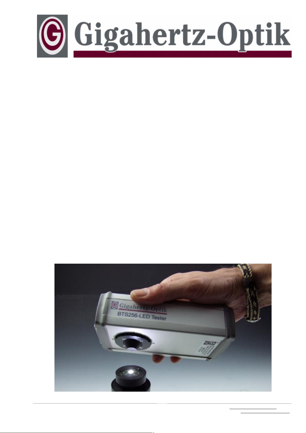
Picture 5.1: State of the art high intensity LED
Guidelines / Manual
Version 01.2009-01
Hazard Information:
Useage Hazard:
The BTS256-LED is a light measurement instrument designed for mobile and laboratory use with capability in many
different kinds of end-user applications. During the measurement the user needs to align the device and read-out
measurement information on a PC display requiring the
user’s full attention. Because of this the instrument should
not be used in insecure or hazardous areas and applications. Training of personnel using the instrument should include this warning.
Light Hazard:
State of the art high power LEDs emit very bright light which
can cause eye damage. Please check and follow safety instructions as provided by the manufacturer of the light
source. Health hazard guidelines are available from radiation protection agencies and occupational health and safety
protection offices.
Perils Clause:
Gigahertz-Optik GmbH, as manufacturer of the BTS256LED measurement instrument, has informed the owner and
operator herein about the possible hazards and risks associated with the use and operation of the device. The owner
and operator of the instrument confirms understanding the
associated risks and hazards. Further, reading the operation manual is a precondition for the successful set-up and
use of the instrument. The operator confirms the careful
and proper use of the measurement set-up to avoid any risk
to himself and others.
BTS256-LED Tester / Page 5
About LED Measurement
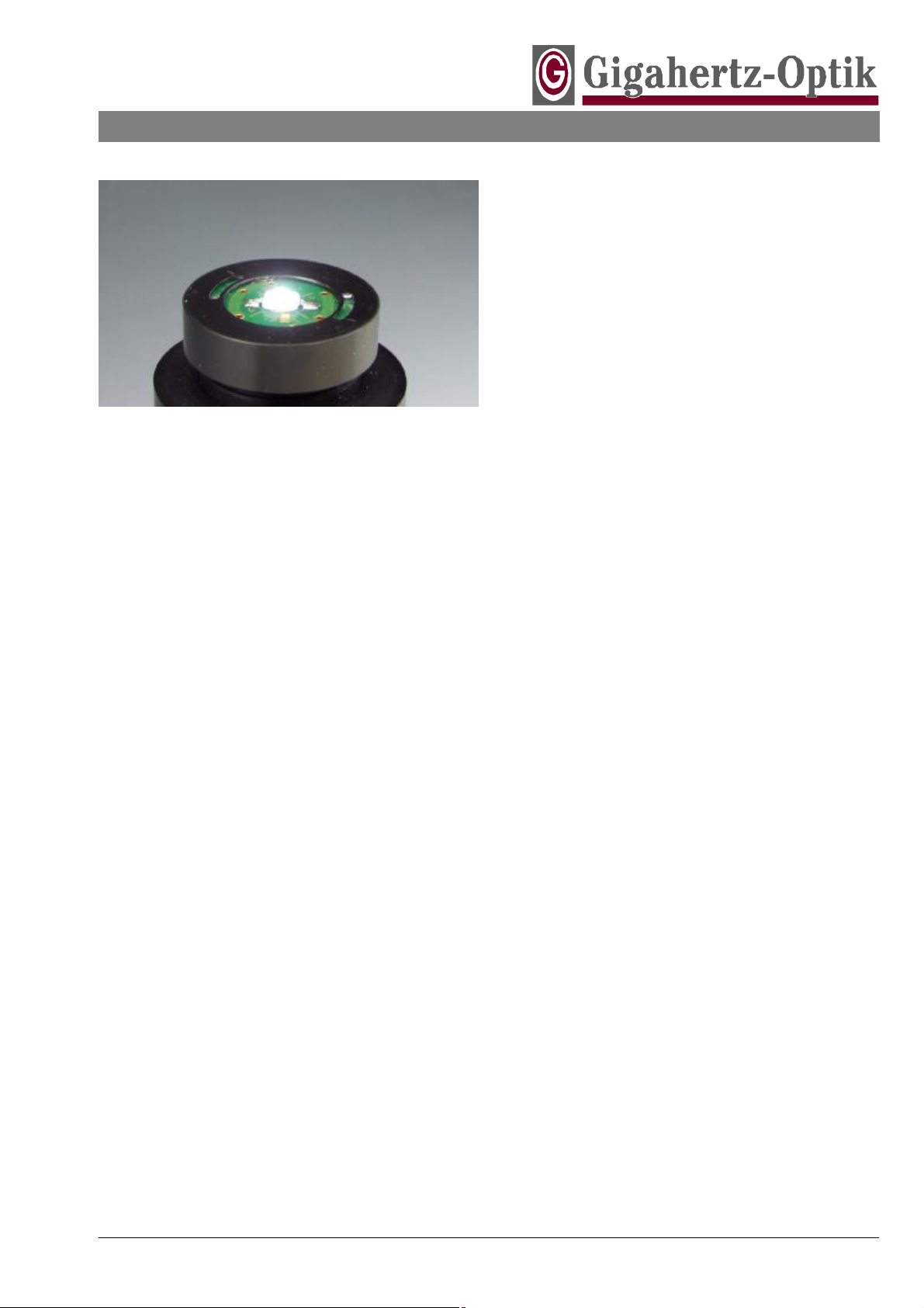
Picture 6.1:
White LED Assembled to DUT PCB of Gigahertz-Optik’s
LEDA2 LED Measurement Adapter simulating Application
Conditions During Qualification Measurement
I [ cd ]
Φ [ lm ]
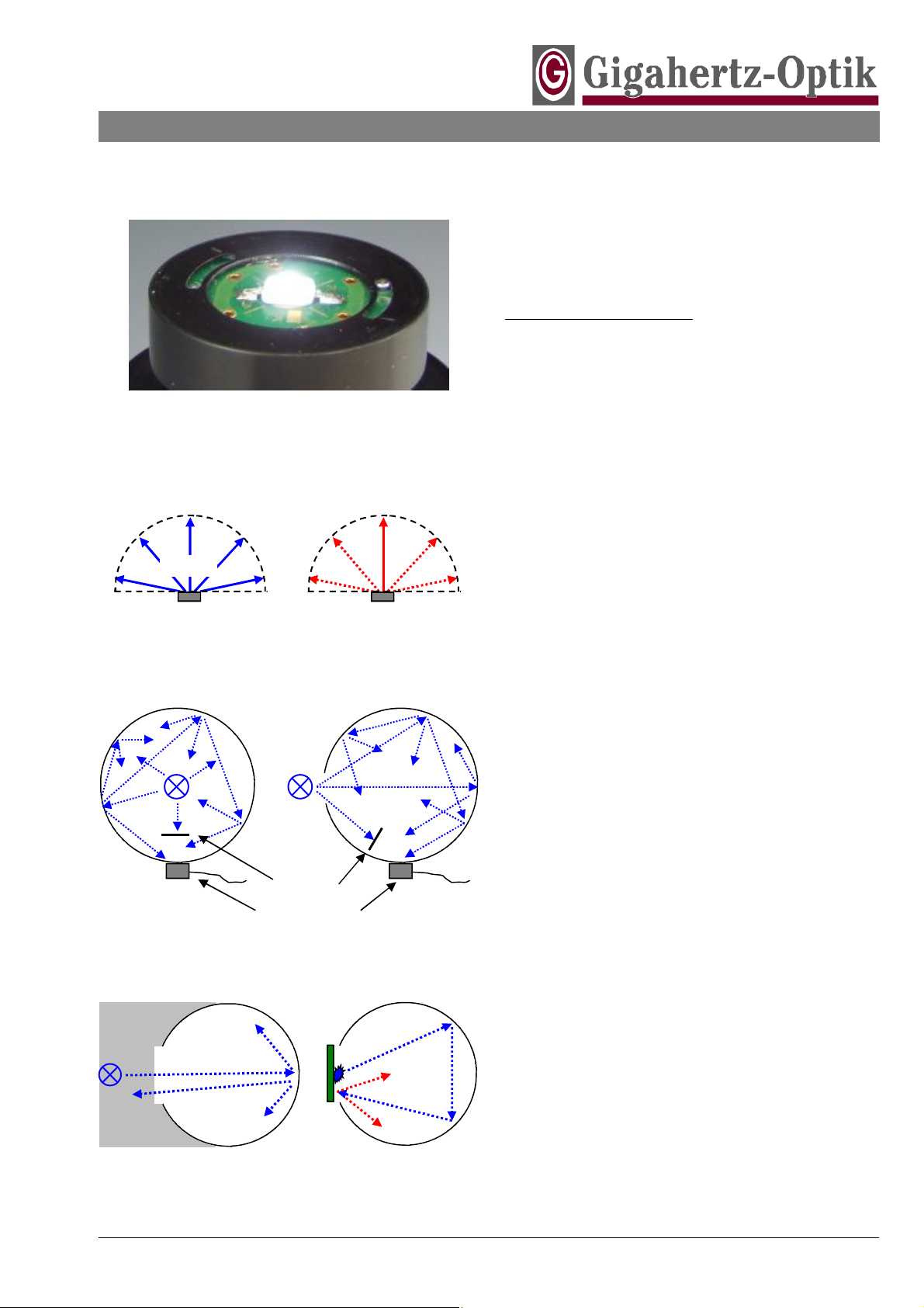
Luminous Flux Luminous Intensity
Picture 6.2: Light Measurement Quantities
Baffle
Light Detector
Picture 6.3: Integrating Sphere Photometer
Calibration: Dark Room
without Re-reflected Light
Picture 6.4: Substitution Effect
Measurement: DUT Reflected Light back into Sphere
Guidelines / Manual
Version 01.2009-01
The BTS256-LED tester is a light measurement device especially designed to analyze the light output of printed circuit board (PCB) mounted and operated Light Emitting Diodes (LED).
Basics of LED Measurements:
LEDs are semiconductor light sources with a high efficiency
electrical power to light power conversion. As with any
semiconductor device, operating temperature effects
changes in performance referred to as a device’s temperature coefficient. In connection with LEDs the temperature
coefficient will effect a reduction in light output and a drift in
color. Operation under high junction temperature conditions
may effect lifetime. Certain ambient operating environments, e.g. high humidity, can impact lifetime and device
specifications as well. Thermal management is of primary
importance to the successful implementation of LEDs.
Sorting or grading of individual LEDs by color differences
caused by tolerances in the semiconductor process is a
common practice offered by most semiconductor manufacturers. But due to differing LED manufacturer’s sorting processes and operating conditions, the LED processing industry accepts the need for in-house measurements. These
measurements should be made with the LED device in its
actual operating state in the application.
The most common light measurement quantity used in
LED testing is luminous flux measured in lumen. This quantity corresponds to LED efficiency by correlation of the total
light output to the electrical power. Measurement of the total
light output in lm instead of luminous intensity in cd produces much better reproducibility because it is independent
of spatial light distribution (picture 6.2) which may be influenced by temperature, humidity, distance, different viewing
angles, misalignment and other experimental error.
Measurement of luminous flux with a goniometric pho-
tometer is the most precise method of measurement. Here
a summation of the spatial luminous intensity distribution
within the hemisphere in front of the LED is performed.
However this is a time and cost intensive method typically
applied in high level R&D and Quality laboratories.
In industry a light meter with an integrating sphere (picture
6.3) are the most common measurement devices employed. This approach offers easy and fast operation as
well as cost effectiveness. The integrating sphere acts as
light integrator for spatially emitting light sources. The integration effect is the result of multiple diffuse reflections of
the light on the diffuse reflecting surface of the hollow
sphere which results in a uniform light distribution at the
sphere surface. The illuminance measured at any position
on the integrating sphere surface is therefore an indicator of
the total flux generated by a light source inside or outside of
the sphere. As with any other measurement device integrating spheres exhibit some typical characteristics which
must be considered in use:
1. The substitution effect is one source of measurement
uncertainty. During calibration of the sphere photometer
some of the light irradiated into the sphere will exit the
BTS256-LED Tester / Page 6
About LED Measurement ( Continued )
Guidelines / Manual
Version 01.2009-01
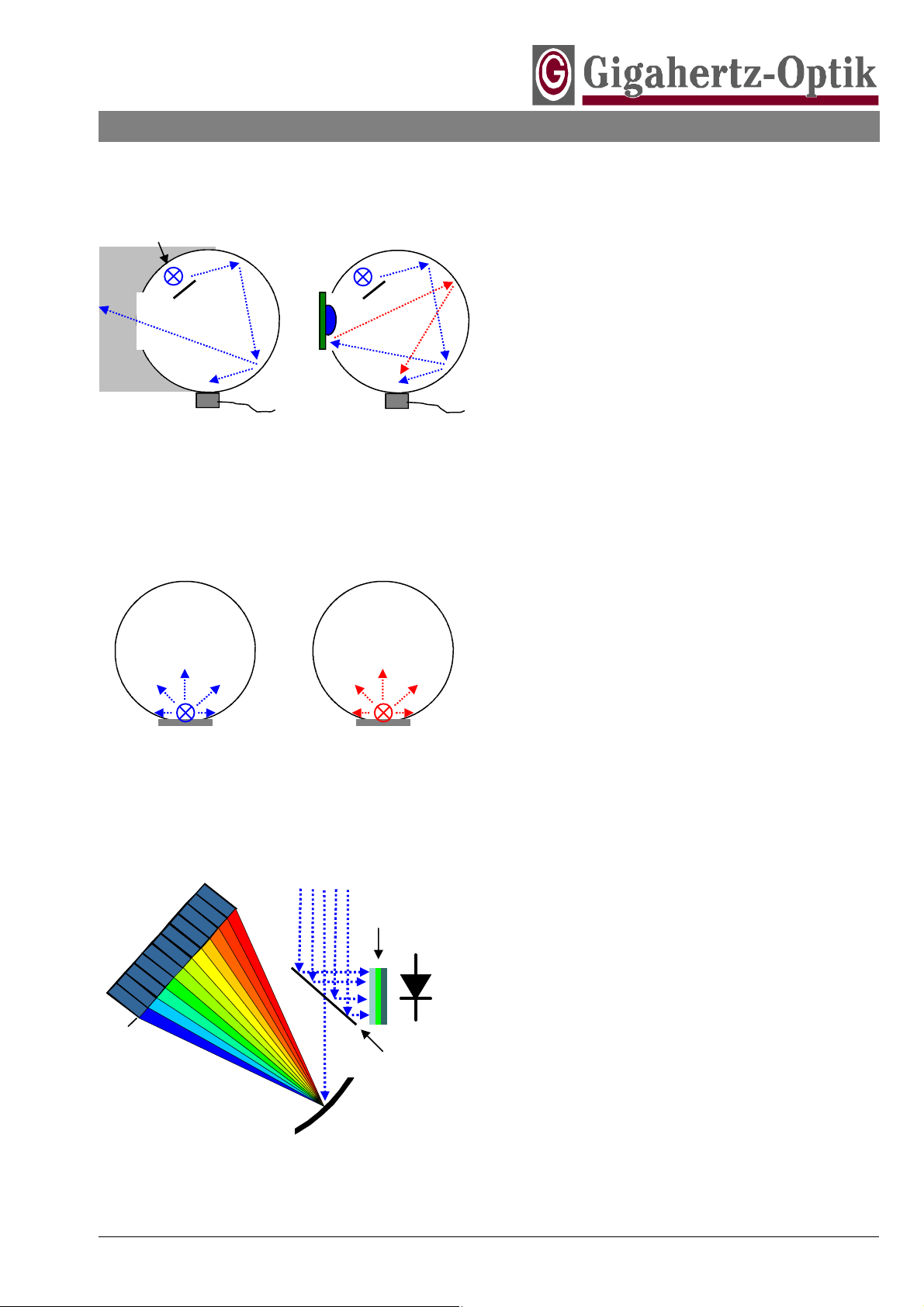
Auxiliary Lamp
Dark Room
Light Detector
Measurement without DUT Measurement with DUT
Picture 7.1: Auxiliary Lamp Use
Picture 7.2: Calibration Strategy with Hemispherical
Calibration Lamp for Diffuse Emitting LEDs
Common Incident Light
Polychromatic or Monochromatic
y
a
r
r
A
e
d
o
i
D
Picture 7.3: BITEC Sensor Base Set-up Design
g
n
i
t
a
r
G
Photometric
Filter
Beam Splitter
sphere through the measurement port and be absorbed
in the dark room. But during actual use, the measurement port of the integrating sphere will be fully or partially covered by the device under test DUT. So light
leaving the sphere through the measurement port will
be reflected back into the sphere adding erroneously to
the DUT light signal. Depending on the spectral reflectivity and color of the DUT the re-reflected light will vary
in intensity and color and effect an unknown measurement error. Auxiliary lamps are used to compensate this
substitution error by measuring the signal of the auxiliary lamp with and without the DUT at the measurement
port of the integrating sphere. The difference in intensity
is used as a correction factor for following measurements of the same kind of DUT.
2. The size of the integrating sphere should be much
larger than the size of the test sample to keep measurement uncertainty low independent of the spatial light
emission characteristic of the test sample. The smaller
the sphere the greater the interference of the uniform
light distribution due to internal baffles, ports and auxiliary lamp. Small size integrating sphere sensors used in
mobile light meters must therefore be calibrated by a
calibration lamp with spatial emission characteristic
close to that of the device under test. Light meters with
small size integrating spheres designed for wide angle
emitting LEDs may have increased measurement uncertainty when used to measure narrow beam emitter type
LEDs. In applications involving large emitting area LED
sources and LED arrays the only choice is large diameter integrating spheres.
Besides light intensity, spectral intensity distribution and
color data are important test properties in LED testing. The
spectrometer is the most commonly used measurement device for these types of measurements. However the photodiode array spectrometer employing low cost CCD sensors
is limited by sensor intensity linearity and stray light characteristics. An alternative method is to mate a photodiode with
a diode array sensor, e.g. Gigahertz-Optik’s BiTech Sen-
sors BTS (picture 7.3). It’s photodiode with photometric
sensitivity provides a precise linear ratio between light input
and signal output over a very wide dynamic range for very
accurate luminous flux measurements. Spectral distribution
including the wavelength of peak intensity is provided by it’s
diode array sensor. The spectral data enables the measurement device to calculate color data (xy and u’v’ color coordinates, color temperature, color rendering index and domi-
Photodiode
nant wavelength). A spectral resolution of 5nm is recommended for the color calculation.
The sensitivity of photodiode sensor based light meters
can be controlled over different gain ranges due to
switchable feedback resistors in the amplifier circuit. The
response time is short and independent of the gain over a
wide range.
The sensitivity of photodiode array is controlled by integration time so the lower the light level the longer the measurement time. But longer integration times effect increases
BTS256-LED Tester / Page 7
About LED Measurement ( Continued )
Guidelines / Manual
Version 01.2009-01
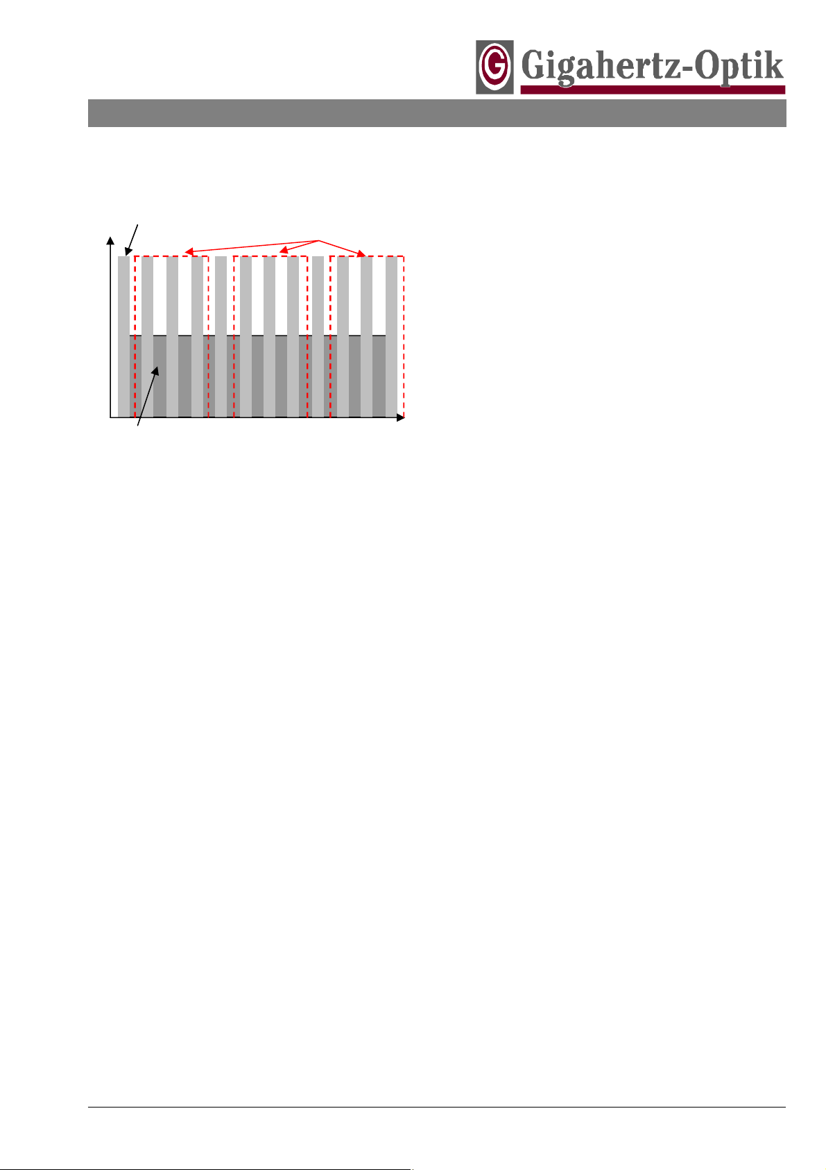
Peak Intensity
Intensity
Average Intensity
Picture 8.1: Pulse Width Modulated Signal
Frequency Synchronized
Measurement Sequences
Time
in both signal and dark signal. To improve the signal to
noise ratio offset compensation becomes an important rule
for diode array sensors. Best offset compensation is done
with a dark signal measurement using the same integration
time as the signal measurement. A remote controlled shutter supports synchronized integration time on-line offset
compensation. Low light detection with CCD photodiode
array technology can be achieved by employing offset compensation in combination with very long integration times.
Due to thermal drift LEDs are often operated in pulse
width controlled mode (picture 8.1). The reduced average
power under this mode produces a higher peak intensity in
light output. For accurate flux measurements at lower frequency the light meter should be synchronized to the operation frequency of the LED. The synchronization to the
light output of the LED can be done with photodiodes because of their fast response time.
BTS256-LED Tester / Page 8
 Loading...