


GigaFast WF 727-AEX IEEE 802.11 b/g
WLAN CardBus adapter
User Guide
1

Copyright
The contents of this publication may not be
reproduced in any part or as a whole, stored,
transcribed in an information retrieval system,
translated into any language, or transmitted in
any form or by any means, mechanical,
magnetic, electronic, optical, photocopying,
manual, or otherwise, without prior written
permission.
Trademark
All product, company, and brand names are
trademarks or registered trademarks of their
respective companies. They are used for
identification purpose only. Specifications are
subject to be changed without prior notice.
2

Table of Content
1
: Introduction
: Features
: Package Contents
: System Requirements
: What is Wireless LAN?
: Wireless LAN Modes
: Notes on Wireless LAN Configuration
2
: Hardware Description
: Inserting the Wireless Adapter
: LED Indicators
: Ejecting the Wireless Adapter
3
: Installation Overview
: Installation under Win 98SE / Win ME
: Installation under Win 2000 / Win XP
4
: Configuration Utility
Appendix
A: Troubleshooting
B: Specifications
C: Technical Support / Warranty info
3

SECTION 1:
INTRODUCTION:
The WF 727-AEX WLAN Card Bus Adapter provides high-speed wireless
link and networking for PC Card enabled desktops or notebooks. Users
can have wireless connectivity simply by plugging the device into a PC
Card Bus slot and installing the driver/utility on a desktop or notebook.
When used with WLAN Access Point or WLAN Router, mobile workers
can move freely, while maintaining seamless links to the wired LAN.
FEATURES:
Uses 2.4GHz frequency band, which complies with worldwide
•
requirement
• Standards compatible with IEEE 802.11g and backwards compatible
with IEEE 802.11b
• Enciphering/deciphering of wireless data by the implementation of
the WEP algorithm
• Wire-free access to networked resources from anywhere beyond the
notebook
• Allow users move between Access Points without resetting their
connection reconfiguration
• Delivers data rate up to 54Mbps
• Supports 54,48,36,24,18,12,11,5.5,2, and 1Mbps
• Provide Wireless PCMCIA Adapter Configuration utility
PACKAGE CONTENTS:
• WF 727-AEX Card In box
• WF 727-AEX CD-ROM In box
• WF 727-AEX Warranty card In box
• WF 727-AEX drivers/utility On CD
• WF 727-AEX User’s Guide On CD
4

SYSTEM REQUIREMENTS:
Before installation, please check your system in advance and ensure it
meets the minimum requirements as described below.
• Processor: Intel Celeron / Pentium II /Pentium III / Pentium 4; AMD
Duron/Athlon
• Operating System: Microsoft Windows 98SE / ME / 2000 / XP
• System memory: 32MB at least
• Hard Drive Free Space: 5MB
• One available Card Bus PCMCIA slot (32bit)
What is Wireless LAN?
Wireless Local Area Network (WLAN) systems offer a great number of
advantages over traditional wired systems. WLAN is flexible and easy to
setup and manage. They are also more economical than wired LAN
systems. Using radio frequency (RF) technology, WLAN transmit and
receive data through the air. WLAN combine data connectivity with user
mobility. For example, users can roam from a conference room to their
office without being disconnected from the LAN. Using WLAN, users can
conveniently access shared information, and network administrators can
configure and augment networks without installing or moving network
cables.
WLAN technology provides users with many convenient and cost
saving features:
• Mobility: WLAN provide LAN users with access to real-time
information anywhere in their organization, providing service
opportunities that are impossible with wired networks.
• Ease of Installation: Installing is easy for novice and expert users
alike, eliminating the need to install network cables in walls and
ceilings.
• Scalability: WLAN can be configured in a variety of topologies to
adapt to specific applications and installations. Configurations are
easily changed and range from peer-to-peer networks suitable for a
small number of users to full infrastructure networks of thousands of
users roaming over a broad area.
5

Wireless LAN Modes:
Wireless LANs can be configured in one of two ways:
1. Ad-hoc Networking:
Also known as a peer-to-peer network, an ad-hoc network is one that
allows all workstations and computers in the network to act as servers to
all other users on the network. Users on the network can share files, print
to a shared printer, and access the Internet with a shared modem.
However, with ad-hoc networking, users can only communicate with other
wireless LAN computers that are in the wireless LAN workgroup, and are
within range.
2. Infrastructure Networking:
Infrastructure networking differs from ad-hoc networking in that it includes
an access point. Unlike the ad-hoc structure where users on the LAN
contend the shared bandwidth, on an infrastructure network the access
point can manage the bandwidth to maximize bandwidth utilization.
Additionally, the access point enables users on a wireless LAN to access
an existing wired network, allowing wireless users to take advantage of
the wired networks resources, such as Internet, email, file transfer, and
printer sharing. Infrastructure networking has the following advantages
over ad-hoc networking:
• Extended range: each wireless LAN computer within the range of
the access point can communicate with other wireless LAN
computers within range of the access point.
• Roaming: the access point enables a wireless LAN computer to
move through a building and still be connected to the LAN.
• Wired to wireless LAN connectivity: the access point bridges the
gap between wireless LANs and their wired counterparts.
Notes on Wireless LAN Configuration
When configuring a wireless LAN (WLAN), be sure to note the following
points:
• Optimize the performance of the WLAN by ensuring that the
distance between access points is not too far. In most buildings,
WLAN Adapters operate within a range up to 125 m, depending on
the thickness and structure of the walls.
• Radio waves can pass through walls and glass but not metal. If
there is interference in transmitting through a wall, it may be that the
wall has reinforcing metal in its structure. Install another access
point to circumvent this problem.
6

• Floors usually have metal girders and metal reinforcing struts that
interfere with WLAN transmission.
SECTION 2:
Hardware Description
The Wireless PCMCIA Adapter is encased in a stainless compact frame
and has a 68-pin connector for attaching to the CardBus port of notebook.
Inserting the Wireless PCMCIA Adapter:
Follow the procedure below to insert the Wireless PCMCIA Adapter.
With 68-pin connector of the card facing the CardBus slots on notebook.
Make sure the GigaFast product sticker is facing up. Slide the card all the
way into the empty CardBus slot
.
LED Indicators:
The following describes the meaning of LED indicators:
POWER: Indicates that the Adapter is powered on (solid green).
ACT: Indicates Active status. The LED is off while the wireless connection
is linked. If the LED is blinking green, the adapter is searching for possible
wireless connection or transmitting the data via wireless.
Ejecting the Wireless PCMCIA Adapter:
• After disconnecting from the LAN, you can eject the Wireless
PCMCIA Adapter from the PC Card slot of notebook.
• Most notebooks have an eject lever or button for ejecting PC cards.
Consult your notebook manual for details.
• After hardware installation is completed, please go to next Chapter
to install driver on different Operating System.
7
SECTION 3:
INSTALLATION OVERVIEW
Start your computer and then insert the Installation/Documentation CD in
the computer’s CD-ROM drive. The auto-run installation application will
detect the Operating System you are using automatically.
Note1: If the auto-run installation application didn’t start automatically, you
can utilize the Windows Explorer to browse CD content and run setup.exe
manually.
Note2: To prevent potential problems during installation, please use the
auto-run installation tool on the CD to finish the driver installation before
you plug WF 727-AEX Adapter into the computer.
INSTALLATION UNDER Win98SE / Win ME
Step 1. Please insert the Device CD, Win98SE / Win ME will
automatically start ‘Autorun’.
8
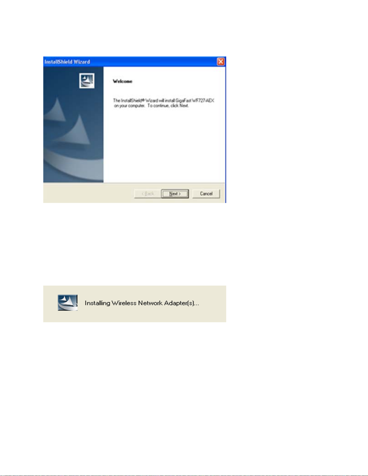
Step 2. Welcome dialog will appear, please click NEXT
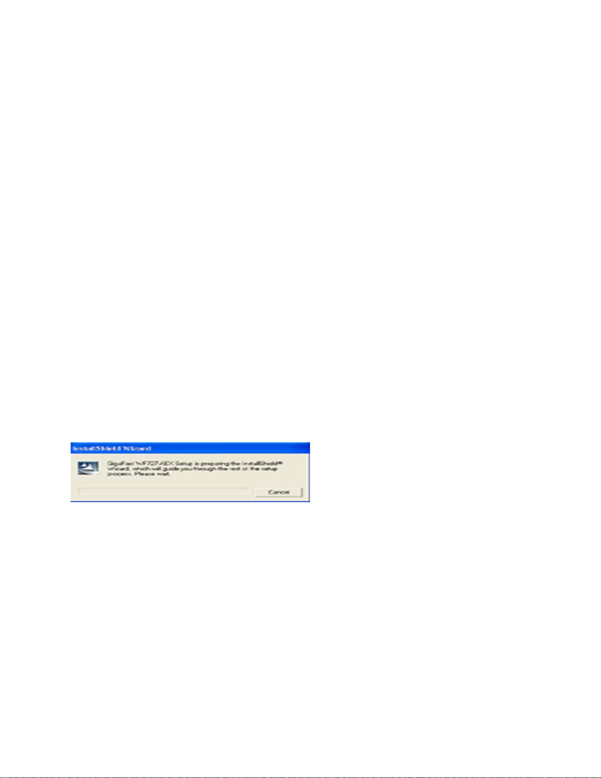
Step 3. Starting to Copy
Step 4. Please click Continue Anyway for this Warning page
9
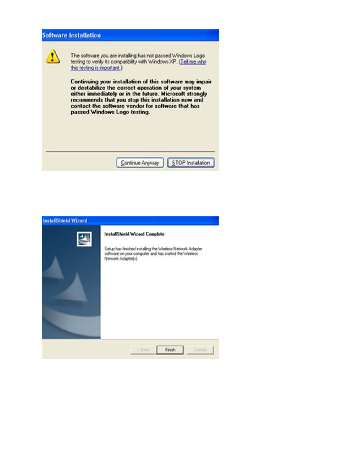
Step 5. Click Finish to complete installation
Step 6. After you have installed Utility, hold the Adapter with the logo
facing up, and insert the card into the slot, applying just enough pressure
to make sure it is fully seated. Win 98SE/Win ME automatically detect the
Adapter, briefly opens a New Hardware Found window, and starts
10
collecting information for a driver information database. When Win 98SE /
Win ME is ready to configure the new hardware, it opens the Add New
Hardware Wizard dialog box as shown, Click Next.
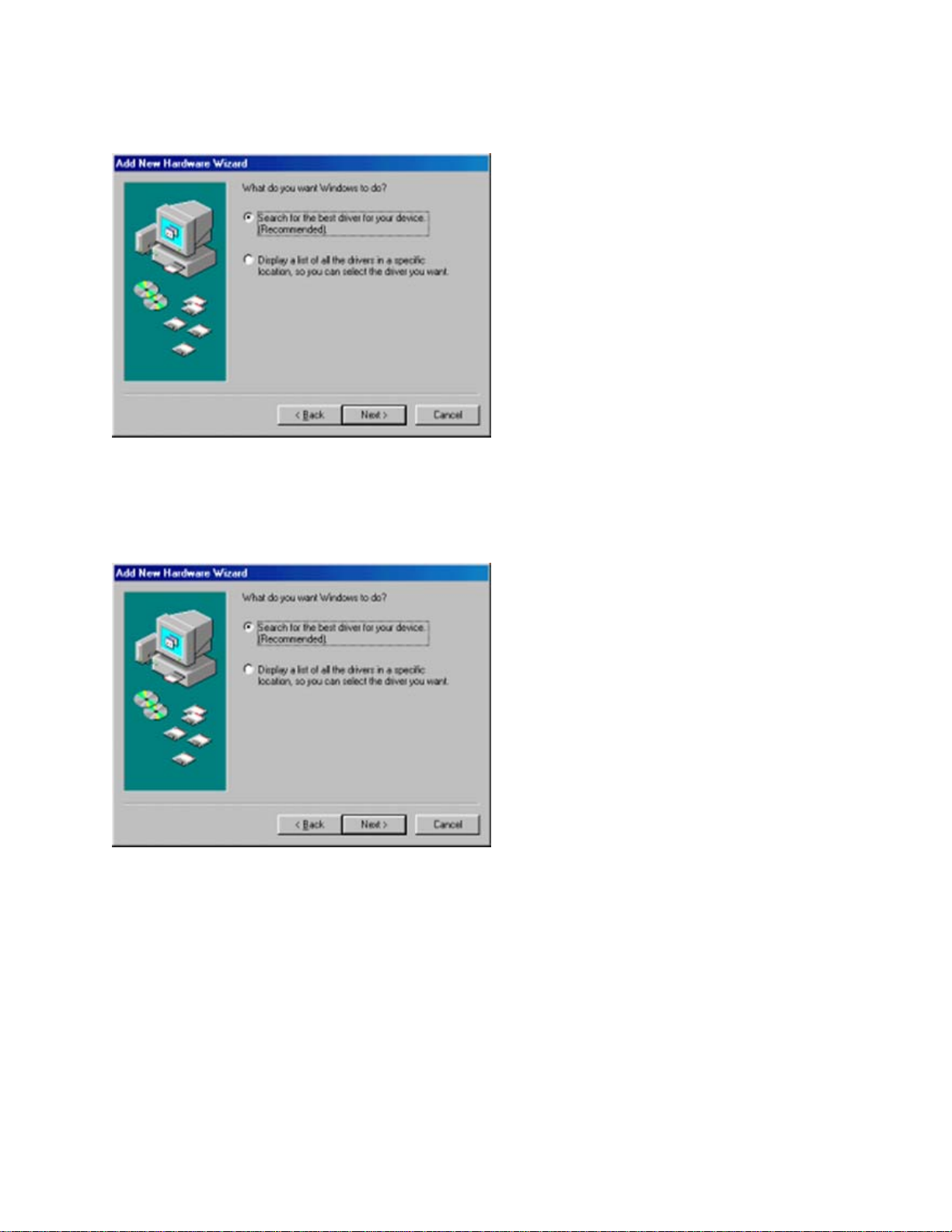
Step 7. A dialog box appears asking what do you want Windows to do.
Select Search for the best driver for your device (recommended) and click
Next.
Step 8. Please choose CD-Rom driver and Click Next button to find device
driver.
11

Step 9. After the hardware wizard finds the installation files in the system,
it displays the search results:” Windows driver file search for the device:
GigaFast WF 727-AEX.” Click Next to copy the required files.
12

Step 10. Installation must use some path files, Please insert the Windows
98 SE System CD. (If you OS is Windows 98SE). Click Ok to continue the
installation.
Step 11. Starting Copy
Step 12. The Add New Hardware Wizard window appears stating that
13

Windows has finished installing the software that your new hardware
device requires. Click Finish.
Step 13. The System Settings Change window states:” To finish setting up
your new hardware, you must restart your computer. Do you want to
restart your computer now?” Remove the software CD and click Yes to
restart the computer.
Step 14. After the computer restarts, double click the My Computer icon
on your desktop. In My Computer window, double click the Control Panel
icon. In Control Panel window, double click the Network icon.
14

Step 15. Select the TCP/IP-> GigaFast WF 727-AEX for
setting the IP address. Click Properties.
15

Step 16. Set IP address and Subnet Mask. You can select either Static or
DHCP setting. If you use the static IP setup then please enter the IP
address and Subnet masking. You should ask your network administrator
for an address, and then type it into the blanket boxes as below. Then
click OK to return to Step 10 Network dialog box.
If your network has a DHCP server and Access Point supports DHCP. IP
address can be automatically assigned to this device. Choose Use DHCP
for WINS Resolution in WINS Configuration then clicks OK to return to
Step 10 Network dialog box.
16

Step 17. The System Settings Change: “To finish setting up your new
hardware, you must restart your computer. Do you want to restart your
computer now?” Click Yes to restart the computer.
* Please refer the configuration utility section to configure your WF 727AEX WLAN CardBus adapter
17

INSTALLATION UNDER WINDOWS 2000 / Win XP
Step 1. Please insert the Device CD, Win 2000 / Win XP will start the
autorun.
Step 2. Welcome dialog will appear, please click NEXT
Step 3. Starting to Copy
18

Step 4. Please click Continue Anyway for this Warning page
Step 5. Click Finish to complete installation
19

Step 6
facing up, and insert the card into the slot, applying just enough pressure to
make sure it is fully seated. Win XP/ Win 2000 automatically detects the Adapter,
briefly opens a New Hardware Found window, and starts collecting information
for a driver information database. When Win 2000 / Win XP is ready to configure
the new hardware, it opens the Add New Hardware Wizard dialog box as shown,
After you have installed Utility, hold the CardBus adapter with the logo
Click Next.
Step 7. After the hardware wizard finds the installation files in the
system, it displays the search results. Please Click Next to
copy the required files.
20

Step 8. Please click Continue Anyway for this Warning page
21

Step 9. The Add New Hardware Wizard window appears stating that
Windows has finished installing the software that your new hardware
device requires. Click Finish.
After finished install driver and utility on your system. First thing we
will see the Utility Icon in the right corner at the taskbar. Please refer
section 4 to configure your WF 727-AEX WLAN CardBus adapter.
22

SECTION 4:
Configuration Utility
WLAN PC Card uses its own management software. All functions
controlled by user are provided by this application. When you insert
the WLAN PC card into the PCMCIA slot, a new icon- should appear
in your icon tray automatically wait a while.
If the icon is in red, it means that WLAN PC Card configuration is
invalid or incomplete.
Double click on that icon will show you the screen as shown below.
Left click on advanced button.
23

Wireless Networks Configuration
The Configuration Tab contains several fields where operating
parameters of the driver can be viewed or changed. Changes to any
of the parameters in this panel can be applied to the driver without a
need to restart the PC.
24

Network Mode
Left click Advanced button .This field allows you to select from a list
of supported Network “Modes”. The modes displayed will have three
values: “Infrastructure”, “Ad Hoc”.
• Infrastructure- The infrastructure mode of operation requires the
presence of an 802.11b/g Access Point. All communication is
done via the Access Point, which relays packets to other
wireless clients in the BSS as well as to modes on a wired
network such as Ethernet.
• Ad Hoc- This is the peer-to-peer mode of operation. All
communication is done from Client to Client without the use of
an Access Point. 802.11 Ad Hoc networking uses the same
SSID for establishing the wireless connection. In this mode the
Channel number will be found automatically.
25

SSID
SSID is the group name that will be shared by every member of your
wireless network. You will only be able to connect with an Access
Point, which has the same SSID
26

Encryption
You may desire an additional measure of security on your wireless
network, which can be achieved by using WEP (Wired Equivalent
Privacy) encryption. WEP encrypts each frame transmitted from the radio
using one of the Keys entered from this panel.
When an encrypted frame is received it will only be accepted if it decrypts
correctly. This will only happen if the receiver has the WEP Key used by
the transmitter.
To be written to the driver and registry, each key must consist of hex
digits, which means that only digit 0-9 and letters A-F are valid entries. If
entered incorrectly program will not write keys to a driver.
You can set this to disable, 40 bits (64bits) or 128 bits.
27

Link Status display
This screen shows the information of the wireless network the
adapter is connecting to, linking time and link status.
28

Statistics display
This screen shows the information of the device LED status.
Accumulated Total of the sent or receive packets.
29

Site Monitor display
Please wait system to scan, all access point within detectable range will be found
and their related information will be displayed, or select
Ad hoc networks only display peer to peer service.
30

Information display
About tab shows the product version including the detail of Driver, Configuration
Utility, and NIC firmware version. Users must use this version number when
reporting their problems for technical support.
31

Appendix A: Troubleshooting
Symptom: The LED is off.
Possible Remedy: Make sure the PC Card is inserted properly. Otherwise
contact Gigafast technical support.
Symptom: The LED is always on not blinking.
Possible Remedy: Make sure that you have installed the driver from attached
CD. Otherwise contact Gigafast technical support.
Symptom: The LED is blinking but the PC Card icon does not appear in your
icon tray.
Possible Remedy: Make sure that you have installed the Utility from attached
CD.
Symptom: The PC Card icon is red.
Possible Remedy: It means there is no wireless link.
1. Make sure there is any 802.11b or 802.11g device in the servicing area.
2. Double click the icon to pop up the configuration window
a. Make sure they are sharing the same SSID and channel. If the SSID is
same, you could press the Link Info → Re-Scan to scan the channel to link.
b. Make sure they are operating under same authentication type. WEP
function has to be enabled, if Shared Key Authentication is the selection, and the
secret Keys have to be same in the communicating group.
3. Position the antenna to gain the maximum RF power and make sure there is
no metal objects, electron devices or cordless phone in the vicinity.
Symptom: The PC Card icon is green, but can’t access wired-LAN
Possible Remedy:
1. Make sure there is any 802.11b or 802.11g AP in your LAN.
2. Make sure the PC Card is configured as infrastructure mode.
3. Make sure the Network setting is proper. You could check and modify through
My Computer → Control Panel → Network → TCP/IP / NetBEUI / →
Gigafast WF 727-AEX→ Content.
Symptom: The PC Card icon is green, but can’t share files with others.
Possible Remedy: Make sure the file and printer sharing function is enabled.
You could enable the function by checking the icon of My Computer → Control
Panel → Network → file and printer sharing → I want to be able to give
others to access to my files.
Symptom: Slow or erratic performance
Possible Remedy: Try changing the channel of the communicating group or
move your device closer to the communicating device.
32

Appendix B: Specifications
Standards Supported:
IEEE 802.11b/g standard for Wireless LAN
Compliant with ETS 300-328, ETS 300-826, and EN60950.
Compliant with FCC Part 15
Radio Specifications:
Frequency Range: 2.4-2.4835 GHz, Direct Sequence Spread Spectrum
Antenna system: Two integrated antenna
Mobility: Seamless roaming across cell boundaries with handover
Power Specifications:
Operating Voltage: +3.3 / 5 Voltage DC
Continuous Transmitting: 330mA
Continuous Receiving: 280mA
Network Architectures:
Infrastructure / Ad Hoc
Data Rate:
802.11g: 6/9/12/18/24/35/48/54 Mbps
802.11b: 1/2/5.5/11 Mbps
Security:
64~128 bit WEP
RF Output Power:
12~15 dbm
Range:
802.11g: 54 Mbps up to 50 m LOS, 20 m indoors
18 Mbps up to 150 m LOS, 75 m indoors
802.11b: 11 Mbps up to 180 m LOS, 60 m indoors
1 Mbps up to 570 m LOS, 125 m indoors
Interface:
32 bit CardBus (Type II)
Environment:
Operation temperature: 0 Cº ~ + 55 Cº
Storage temperature: -10 Cº ~ + 70 Cº
Humidity: 5 ~90% non-condensing
Number of Channels
Europe: CH 1-13
US: CH 1-11
France: CH 10-13
Japan: CH 1-14
Driver Supported
Microsoft Windows 98 SE / Windows ME / Windows 2000 / Windows XP
Certification FCC, CE
33

Appendix C: Technical Support / Warranty
info
Gigafast Technical Support Department
Hours of Operation:
Monday thru Saturday 8AM - 8PM
Excluding Holidays
(888) GFE-6788 or (888) 433-6788
techsupp@gigafast.com
Limited Warranty
Limited Warranty Statement: GigaFast Ethernet Solutions Inc. ("GFE") warrants its products to be free from defects in
workmanship and materials, under normal use and service, for the applicable warranty term. All GFE products carry a standard
limited warranty from the date of purchase from GFE or its Authorized Reseller. GFE may, at its own discretion, repair or replace
any product not operating as warranted with a similar or functionally equivalent product, during the applicable warranty term.
All products that are replaced become the property of GFE. Replacement products may be either new or reconditioned. Any
replaced or repaired product carries either a 30-day limited warranty or the remainder of the initial warranty, whichever is longer.
GFE is not responsible for any custom software or firmware, configuration information, or memory data of Customer contained
in, stored on, or integrated with any products returned to GFE pursuant to any warranty. Products returned to GFE should have
any customer-installed accessory or add-on components, such as expansion modules, removed prior to returning the product
for replacement. GFE is not responsible for these items if they are returned with the product.
Customers must contact GFE for a Return Material Authorization number prior to returning any product to GFE. Proof of
purchase may be required. Any product returned to GFE without a valid Return Material Authorization (RMA) number clearly
marked on the outside of the package will be returned to customer at customer’s expense. For warranty claims within North
America, please call our toll-free customer support number at (888) GFE-6788/(888) 433-6788. Customers are responsible for
all shipping charges from their facility to GFE. GFE is responsible for return shipping charges from GFE to customer.
WARRANTIES EXCLUSIVE: IF A GFE PRODUCT DOES NOT OPERATE AS WARRANTED ABOVE, CUSTOMER'S SOLE
REMEDY SHALL BE REPAIR OR REPLACEMENT OF THE PRODUCT IN QUESTION, AT GFE’S OPTION. THE
FOREGOING WARRANTIES AND REMEDIES ARE EXCLUSIVE AND ARE IN LIEU OF ALL OTHER WARRANTIES OR
CONDITIONS, EXPRESS OR IMPLIED, EITHER IN FACT OR BY OPERATION OF LAW, STATUTORY OR OTHERWISE,
INCLUDING WARRANTIES OR CONDITIONS OF MERCHANTABILITY AND FITNESS FOR A PARTICULAR PURPOSE.
GFE NEITHER ASSUMES NOR AUTHORIZES ANY OTHER PERSON TO ASSUME FOR IT ANY OTHER LIABILITY IN
CONNECTION WITH THE SALE, INSTALLATION, MAINTENANCE OR USE OF ITS PRODUCTS. GFE SHALL NOT BE
LIABLE UNDER THIS WARRANTY IF ITS TESTING AND EXAMINATION DISCLOSE THE ALLEGED DEFECT IN THE
PRODUCT DOES NOT EXIST OR WAS CAUSED BY CUSTOMER'S OR ANY THIRD PERSON'S MISUSE, NEGLECT,
IMPROPER INSTALLATION OR TESTING, UNAUTHORIZED ATTEMPTS TO REPAIR, OR ANY OTHER CAUSE BEYOND
THE RANGE OF THE INTENDED USE, OR BY ACCIDENT, FIRE, LIGHTNING, OR OTHER HAZARD.
LIMITATION OF LIABILITY: IN NO EVENT, WHETHER BASED IN CONTRACT OR TORT (INCLUDING NEGLIGENCE),
SHALL GFE BE LIABLE FOR INCIDENTAL, CONSEQUENTIAL, INDIRECT, SPECIAL, OR PUNITIVE DAMAGES OF ANY
KIND, OR FOR LOSS OF REVENUE, LOSS OF BUSINESS, OR OTHER FINANCIAL LOSS ARISING OUT OF OR IN
CONNECTION WITH THE SALE, INSTALLATION, MAINTENANCE, USE, PERFORMANCE, FAILURE, OR
INTERRUPTION OF ITS PRODUCTS, EVEN IF GFE OR ITS AUTHORIZED RESELLER HAS BEEN ADVISED OF THE
POSSIBILITY OF SUCH DAMAGES.
SOME STATES DO NOT ALLOW THE EXCLUSION OF IMPLIED WARRANTIES OR THE LIMITATION OF INCIDENTAL OR
CONSEQUENTIAL DAMAGES FOR CONSUMER PRODUCTS, SO THE ABOVE LIMITATIONS AND EXCLUSIONS MAY
NOT APPLY TO YOU. THIS WARRANTY GIVES YOU SPECIFIC LEGAL RIGHTS, WHICH MAY VARY FROM STATE TO
STATE. NOTHING IN THIS WARRANTY SHALL BE TAKEN TO AFFECT YOUR STATUTORY RIGHTS.
* GFE will provide warranty service for one year following discontinuance from the active GFE price list. Under the limited
lifetime warranty, ternal and external power supplies, fans, and cables are covered by a standard one-year warranty from in
date of purchase.
34
 Loading...