


HomePlug Ethernet Bridge
PE 902-EBx
User Manual

Copyright
The contents of this publication may not be reproduced in any part of as a whole,
stored, transcribed in an information retrieval system, translated into any
language, or transmitted in any form or by any means, mechanical, magnetic,
electronic, optical, photocopying, manual, or otherwise, without prior written
permission.
Trademarks
All product, company, and brand names are trademarks or registered trademarks
of their respective companies. They are used for identification purpose only.
Specifications are subject to be charged without prior notice.
FCC Interference Statement
This equipment has been tested and found to comply with the limits for a Class B
digital device pursuant to Part 15 of the FCC Rules. These limits are designed to
provide reasonable protection against radio interference in a commercial
environment. This equipment can generate, use and radiate radio frequency
energy and, if not installed and used in accordance with the instructions in this
manual, it may cause harmful interference to radio communications. Operation
of this equipment in a residential area is likely to cause interference, in which
case the user, at his own expense, will b required to take whatever measure are
necessary to correct the interference.
2

Table of Content
Chapter 1: Introduction to the HomePlug Ethernet Bridge……..5
Overview.....................................................................................5
Features……………………………………………………………...5
System Requirements………………………………………………6
Panel………………………………………………………………….7
Wire Diagram………………………………………………………...8
Chapter 2: Installation..............................................................................9
Overview……………………………………………………………...9
Running the InstallShield Wizard…………………………………..9
Chapter 3: Configuration
Overview…………………………………………………………….15
Diagnose Powerline Network……………………………………..16
Part 2: Diagnose a Network HomePlug device……………..17
Setting up Security on a Local HomePlug device……………….19
Setting up Security on a Network HomePlug device……………20
Part 1: Diagnose a local HomePlug device…………………16
Appendix A: Troubleshooting……………………………………………..21
Appendix B: IP Addressing………………………………………………...23
What’s an IP address?..............................................................23
Dynamic IP addressing……………………………………………23
Static IP addressing………………………………………………..23
Checking IP addresses
Setup Static IP addresses………………………………………...28
Part 2: Win 2000/ XP……………………………………….34
Release and Renew an IP address……………………………..40
Part 2: Win 2000/ XP
Part 1: Win 98SE / ME……………………………………..28
Part 1: Win 98SE / ME……………………………………...40
Appendix C: Local Area Network………………………………………. 51
Sharing Files (Win
Part 1: Sharing Folders……………………………………...51
Part 2: Sharing Drives……………………………………….57
Part 3: Accessing Other Computers Shared Files…………...
.......................................................................15
(Win 98SE /ME /2000 / XP)……………..24
………………………………………..46
98SE / ME / 2000 / XP)……………………….51
62
3

Sharing Printers (Win 98SE / ME /2000 / XP)…………………..67
Part 1: Setup print server………………………………67
Part 2: Network Printer Installation……………………70
Access Internet…………………………………………………….81
Part 1: Win 98SE / ME…………………………………..81
Part 2: Win 2000 / XP……………………………………88
Appendix D: Glossary
………………………………………………………95
Appendix E: Product Specification
……………………………………97
Appendix F: Warranty Info....................................................................98
Appendix G: Contact Information
……………………………………….98
4

Chapter 1: Introduction to the HomePlug Ethernet
Bridge
Overview
Thank you on the purchase of the GigaFast HomePlug. Most of us don’t enjoy
buying long and expensive Ethernet cables or pulling the cables from one place
to another, but the GigaFast HomePlug Bridge is one of the easiest ways to
enjoy home or small business networking. Users can now experience a total
network solution with the GigaFast HomePlug. The GigaFast HomePlug
Ethernet Bridge operates on the HomePlug Powerline Specification 1.0 standard,
providing up to 14Mbps bandwidth over home AC wiring. Since the home power
lines are the most pervasive medium in households with multiple outlets in every
room, the HomePlug Ethernet Bridge allows multiple home desktops and
notebooks to be networked to share internet connection, printers, files, and play
games without any additional wiring.
The installation of the Ethernet Bridge only requires that a 10/100Mbps Network
Adapter is installed on the computers. This makes the HomePlug Ethernet
Bridge compatible with any device including Mac, Windows, and UNIX machines.
For security, all GigaFast HomePlug devices are equipped with 56-bit DES
encryption. The private home power grid plus encryption makes HomePlug
significantly more secure than competing technologies.
The GigaFast HomePlug Ethernet Bridge is the best solution for No-New-Wires
home Networking. With easy Plug and Play installation, and the reliability of
GigaFast Ethernet’s products, the GigaFast HomePlug Ethernet Bridge is the
best solution for high speed networking.
Features
• Up to 14 Mbps bandwidth over standard home power lines
• Estimated range of 300 meters in wall power lines
• No problem for the HomePlug signal passing through circuit breaker
• 56-bit DES encryption assure data security
• Encryption done by hardware, with no sacrifice on bandwidth
• Uses IEEE802.3 computer interface
• Plug-and-Play installation
• HomePlug Powerline Specification 1.0 compliant
5

Package Contents
• 1 HomePlug Ethernet Bridge Unit
• 1 HomePlug Quick Start
• 1 HomePlug User Manual
• 1 Installation CD
• 1 Limited Warranty card
• 1 Power Cable
• 1 CAT5/RJ45 Ethernet cable
System Requirements
• At least 2
• Available Ethernet port each computer or network
• Available empty power outlet
• Standard home power line wiring
• CD-ROM drive
HomePlug devices
6
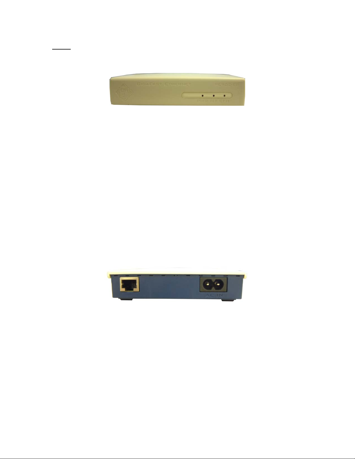
Panel
Front
PWR: On Receive Power
Off Did not receive Power
HP: On Detect other HomePlug devices on the same powerline network
Off Did not detect any other HomePlug devices on the same powerline
network
Eth LED: Act / Link for Ethernet
Blinking: Ethernet activity
Lit: detect Ethernet connection
Back
7
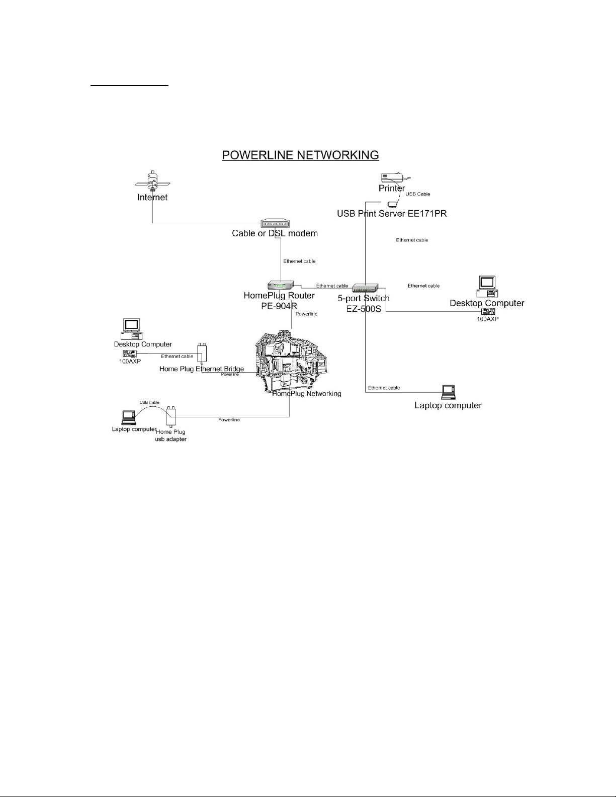
Wire Diagram
8
Chapter 2: Installation
Overview
The installation of the HomePlug Ethernet Bridge will only take minutes. No
setting up for long wires through out the house. Just simply install the software
CD that is included in the box and after installation, physically plug the unit into
the computer and the wall outlet. Users will have options to adjust its security
functions and the platform of the network once everything is installed properly.
For further assistance, please read our Frequently Asked Questions section.
Running the InstallShield Wizard
Please insert the CD into your CD-ROM and wait a moment for the setup screen
to come up. If the CD-ROM does not auto run the CD, please click on ‘Start’ at
the bottom left of your screen (for most Microsoft Windows) and go to ‘Run’.
Type in: (CD Drive Letter):\eth\setup.exe and click ‘OK’
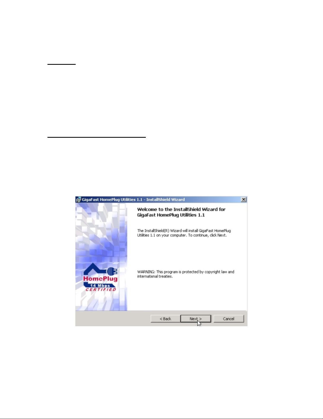
Once the software is loaded it will display a dialog such as is:
Please click on ‘Next’ to continue the installation.
9
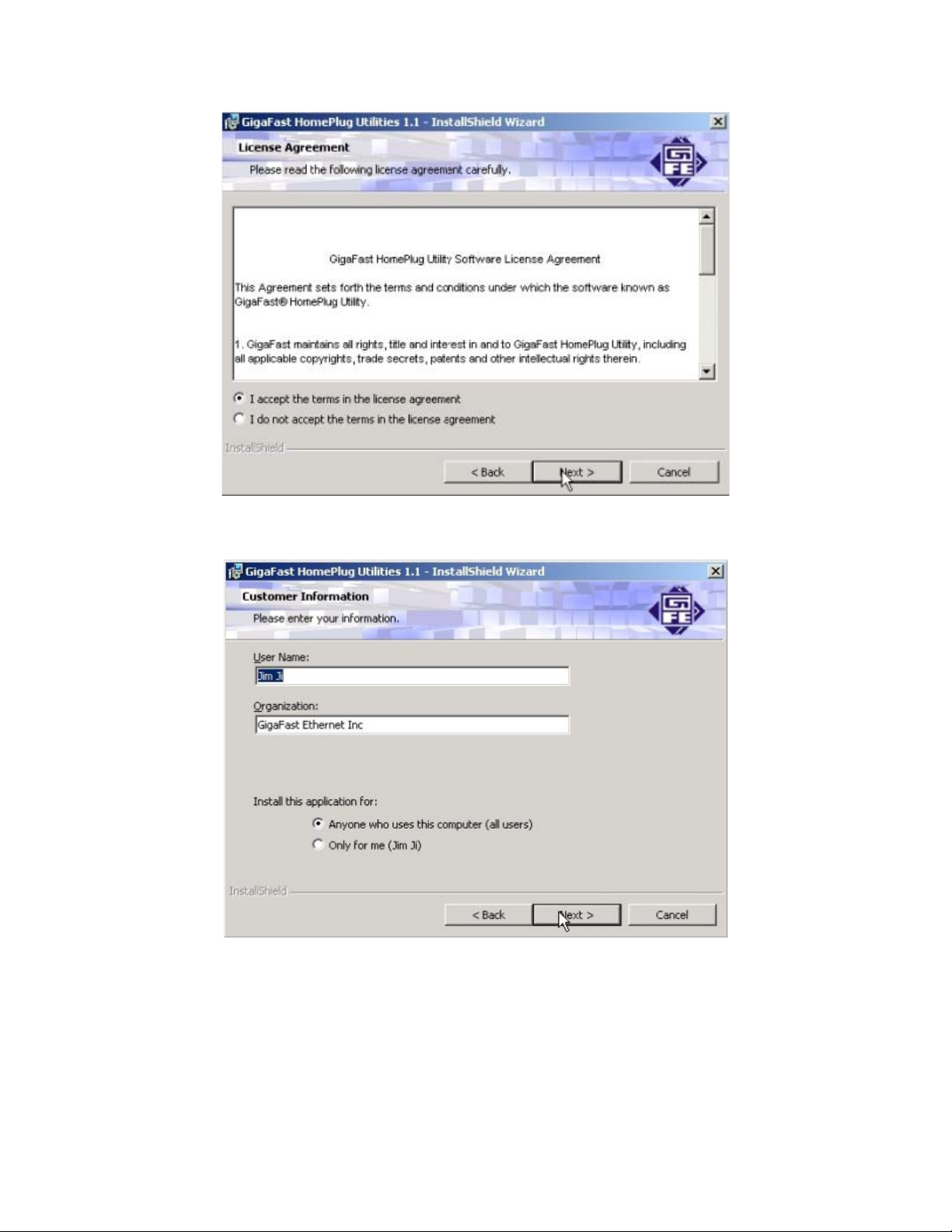
Please accept terms and continue by clicking ‘Next’
On this screen you will be asked to input the User Name and Organization. It is
not crucial to the device itself so enter as desired. The ‘Install this application
for’ will work under the circumstances which multiple logins are applied. For
example: If the user wishes only he/she can use the utility with that particular
account, then bubble in ‘Only for me’. For those without multiple accounts or
wishes to allow all users to access the utility choose ‘Anyone who uses this
computer (all users)’. When finished, click the ‘Next’ button to continue.
10
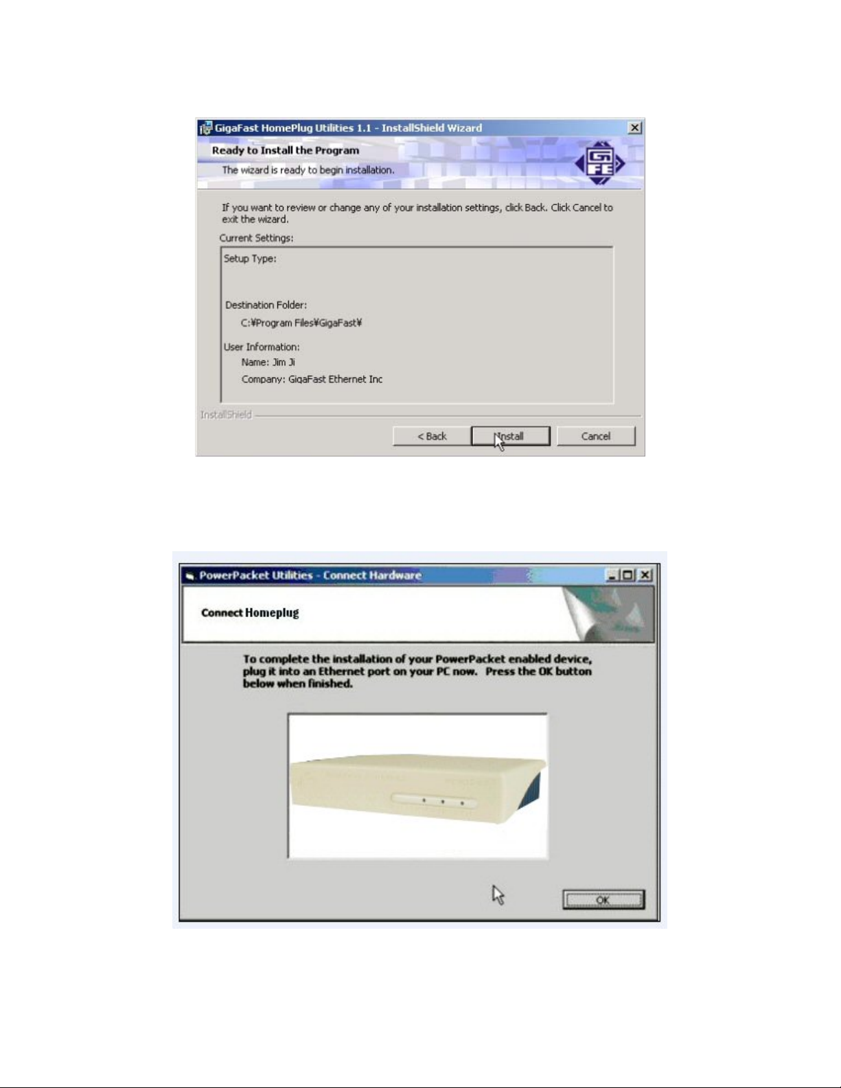
This section allows a user to go ‘Back’ or ‘Install’ the utility. In case if the user
wishes to change the previous options then go ahead and click on ‘Back’ to
change the settings. If not, continue and click the ‘Install’ button.
When you see this screen showing above, please stop at this screen. Process
the next step to install the HomePlug Ethernet Bridge.
11
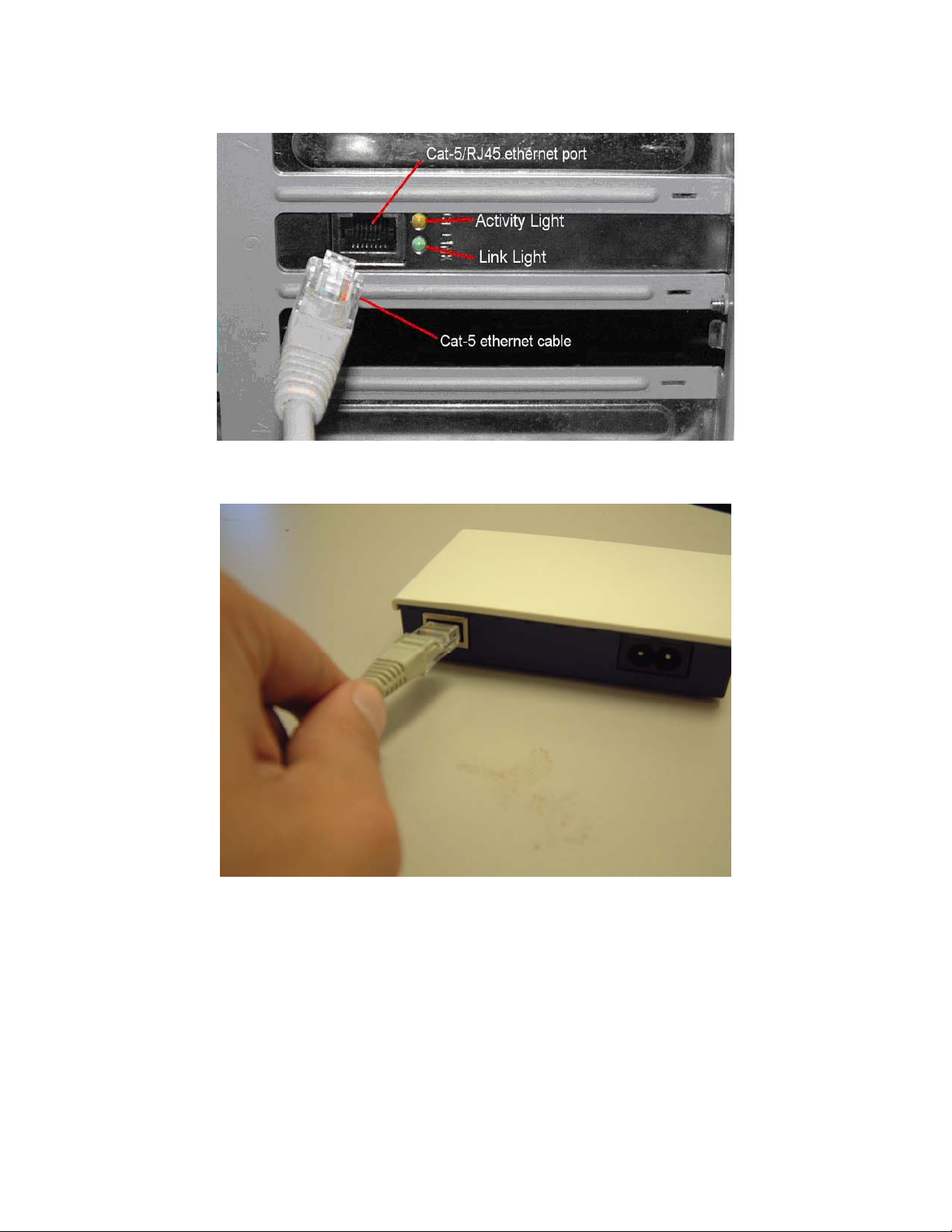
Plug your network cable into the computer’s RJ-45 network adapter port
Plug the other end of your network cable into the RJ-45 port locate at the back
of the HomePlug Ethernet Bridge
12
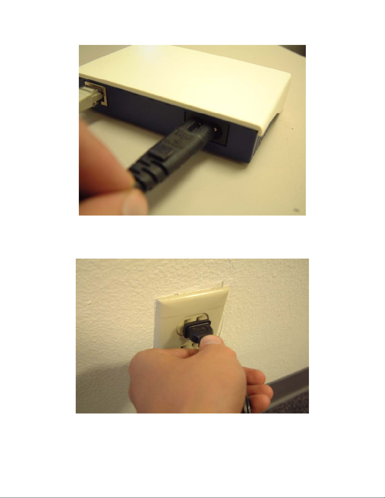
Plug your power connector of your power cable into the power connector at
the back of the HomePlug Ethernet Bridge
Plug the power plug of your power cable directly into a power outlet on the wall
13
**Note: ** Do not plug the device into a UPS or power strip with surge protection.
The HomePlug Ethernet Bridge has its own power filter for protection against
surges.
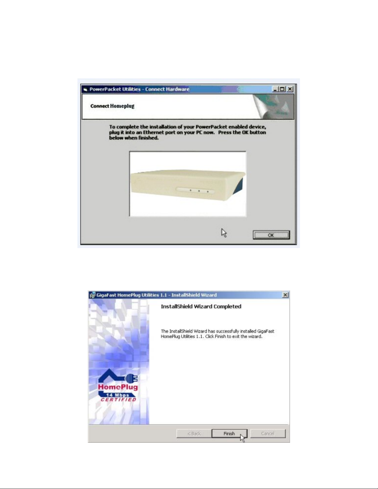
Click ‘OK’ when the unit is connected physically.
14
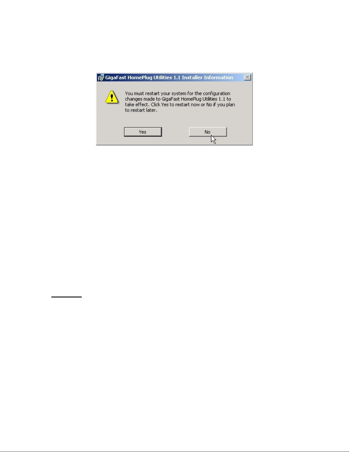
After the installation is complete, click on the ‘Finish’ button and you will be
asked to restart the computer for it to take full effect.
Click the ‘Yes’ button to restart computer or you can choose to restart the
computer later. If so, click on the ‘No’ button.
Chapter 3: Configuration
Overview
The HomePlug device uses 56-bit DES encryption to block outside access. The
key is set by using the HomePlug Configuration Utility on the CD. By default, the
protection is enabled. However, it is recommended that you change the default
network password. All your HomePlug devices must use the same network
password in order for the computers to be networked. Make sure that all devices
are loaded with the same network password.
15
Diagnose Powerline network
Part 1: Diagnose a Local HomePlug Device
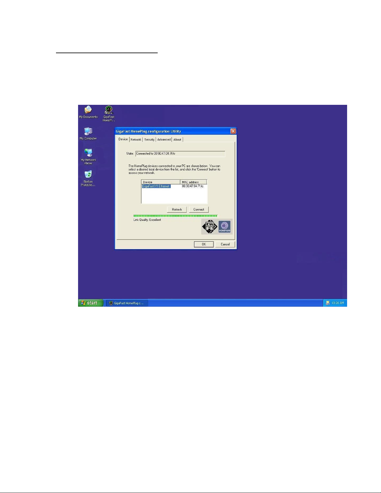
Double click the HomePlug Configuration utility icon on your desktop to open this
utility show in the screen below
The Device tab shows the HomePlug units that are connected to the
current computer. It will also tell Mac Address of each device. It will let
you refresh the window, if you change devices, and also will allow you to
connect to different networks if multiple units are connected to your
computer. The green bar on the bottom of the utility tells the Link Quality
to the device connected to your computer.
*Note* If the Link Quality is poor, and appears red, or the Mac Address of
any of the units connected to this computer appears to be all 0’s, then you
might have a defective unit. Please contact technical support (Appendix
G) **
*Note* If you do not see ANY unit in the device status, and there is a
device connected to your computer, try to unplug all devices, and plug
them back in. Also make sure that the cable connecting your computer to
16
the HomePlug device is the right type and working correctly. If all of this
seems to be correct, and you still receive nothing in the Device window,
please contact technical support (Appendix G).
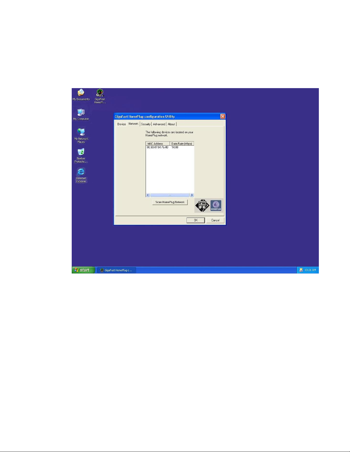
Part 2: Diagnose a Network HomePlug device
The Network tab shows all the other HomePlug Units on your powerline
network. It will represent them by MAC Address, and will also show the
available bandwidth to each unit (Units farther away from the current
computer might have a lower Data Rate, since the distance is farther). If
you add or subtract units from your home network, you might want to reScan, by clicking the “Scan HomePlug Network” button. This will rescan
the network, and refresh with any changes.
**Note** Only units with the same Network Password will be shown,
please check that first, to make sure they all have the same network
password (Case sensitive).
**Note** If a Unit shows MAC Address of all 0’s, this unit might not have a
solid connection, or might not connect at all. If this is the case please
contact technical support (Appendix G).
17

**Note** If there are Units in your home, that you do not see in this
Network scan, try to unplug all devices, and plug them back in (Only do
this with the Units that you do not view in the network screen, you don’t
have to do this with all units. If the problem persists, try to move the unit
closer to this current unit (adjacent plugs on the same wall socket is most
preferable). If the problem still persists and that unit is still not shown on
the network, then the unit might be defective please contact technical
support (Appendix G). Otherwise if you view the unit working, distance
might be the only issue.
18
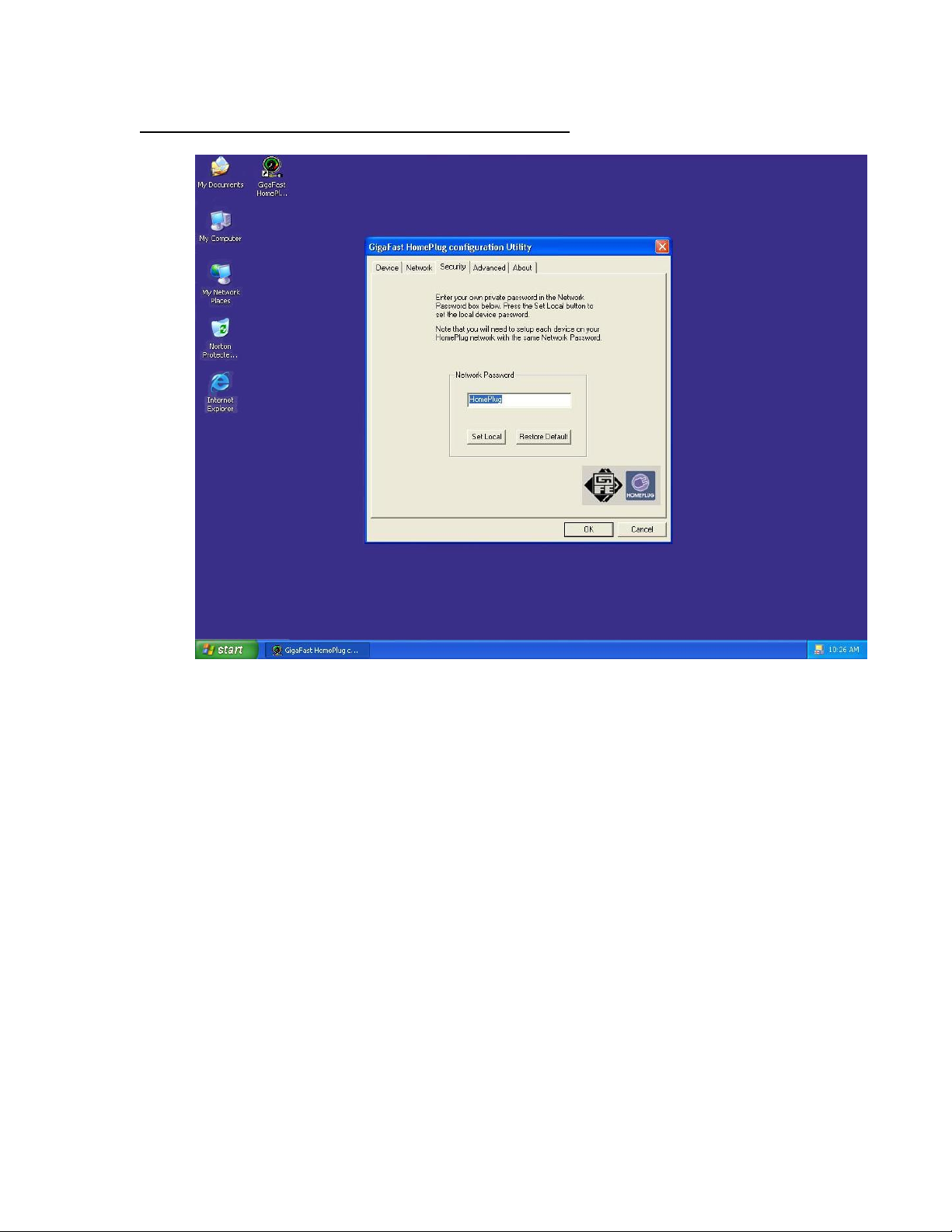
Setting Up Security on a Local HomePlug device
The Security tab will allow you to change the Network Password to the
unit that is currently connected to this computer. This network password
encrypts all data that is sent from this unit using
56-bit data encryption
standard (DES). The DES Encryption is very secure, and very difficult to
crack, therefore your home network is very secure, and very difficult to
breach your home network.
**Note** Every unit on your home network MUST have the same Network
Password for connectivity to be established throughout your home. The
default network password is “HomePlug”.
19
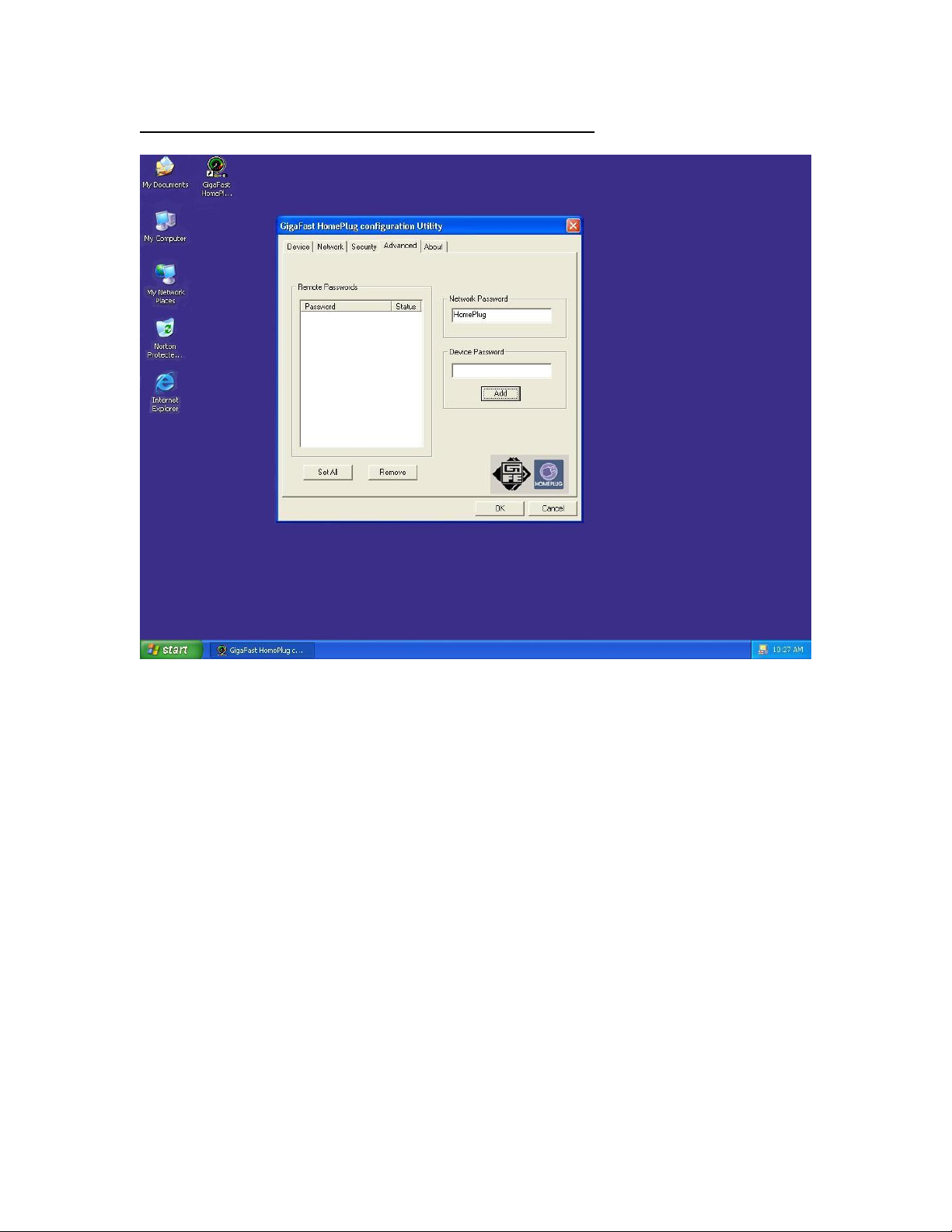
Setting Up Security on a Network HomePlug device
The Advanced Tab will allow users to use one primary computer to control
the Network Password of all units on the home network. First Find the
DEK (Device Encryption Key) Key located on the bottom of each device.
Enter this Key into the Device Password area. Click Add. This Device
Key will then appear in the Remote Passwords Box. Add all the DEK
Keys for each unit in your house. You can then change the password
remotely from one computer. This will allow you to change the password
from one computer, instead of changing the password individually.
**Note** The DEK is unique for EACH HomePlug device. To use this you
will need to input the DEK for each unit.
20

Appendix A: Troubleshooting
Frequently Asked Questions
Q. What’s the speed of HomePlug operate over a standard home power line
network?
A. HomePlug operates up to 14 Mbps bandwidth over a standard home
power line network.
Q. What’s the Estimated Range of HomePlug?
A. Approximately 300 meters in wall power lines (one household).
Q. Will HomePlug work in any home?
A. Any home with copper wiring built-in, since some of the older houses built
before 1950 might have older wiring, it may not work in these instances..
Q. Will HomePlug signal pass through circuit breakers?
A. Yes, HomePlug signal will have no problem passing through circuit
breakers but not through power transformers.
Q. Does Homeplug work with AC input 100 – 240V?
A. Yes, HomePlug works with AC input 100 – 240V.
Q. Does HomePlug cause any interference with other my other home
networking device?
A. No, HomePlug operates in a different frequency band than other power
line control devices and can co-exist with technologies as X-10, CEBus,
and LONworks.
Q. Can my neighbor receive my HomePlug signal?
A. It is possible for your neighbor receive your HomePlug signal between two
adjacent homes. To prevent this happen, please enable the 56-bit DES
security encryption on your HomePlug Device. To do that, you must run
the HomePlug Configuration Utility on each Homeplug device in your
power line network. This will only allow computers with the same security
password to be able to receive information.
21

Q. How do I find out what’s my current speed and my signal strength of my
HomePlug device?
A. Run the HomePlug Configuration Utility, it will show your current speed
and your signal strength.
Q. One of the Powerline LED’s doesn’t light up after I plug the HomePlug
directly into a wall outlet?
A. Test that wall outlet with other electric devices first, make sure that wall
outlet is working properly. Then, try to plug your HomePlug device again,
if the same problem happens again, plug both HomePlug units into
adjacent sockets, and see if the lights light up. If you are still having
problems please contact Technical Support (Appendix G).
Q. The Ethernet LED doesn’t light up on my HomePlug Ethernet Bridge?
A. Most likely, if the Ethernet LED doesn’t light on your HomePlug Ethernet
Bridge is because the Ethernet port on it doesn’t detect a LAN connection.
Check your Ethernet adapter on your computer, and make sure its enable
and working properly. Also, check your Ethernet cable, make sure you
use the right type, it’s plugged in correctly, and it’s working properly.
Q. I can’t connect to internet and other computers on my power line
network?
A. 1. Check your IP address and TCP/IP protocol are set up properly for all
the computers on your power line network (Appendix B) and try to ping
your gateway (Appendix B).
2. See if HomePlug Configuration Utility to detect all other HomePlug
device on your power line network. Try plugging both HomePlug units into
Adjacent sockets and see if the lights light up. If you are still having a
problem, please contact Technical Support (Appendix G).
Q. How many HomePlug devices do I need to setup a powerline network?
A. You must need two or more HomePlug devices to setup a powerline
network.
Q. In order to making the HomePlug Ethernet Bridge working properly, do I
have to install the HomePlug Configuration Utility on every single
computer who has the HomePlug Ethernet Bridge plug into it?
A. No, the HomePlug Configuration Utility is a utility to diagnose or setup
encryption for HomePlug device. Due to HomePlug Ethernet Bridge is a
fully plug & play device, no driver require to install. So technically
22

speaking, the HomePlug Configuration utility is not a requirement to install
on your computer. In other words, you can install the utility, setup the
encryption, and delete it from your computer, but your HomePlug Ethernet
Bridge will still working properly.
Q. How many HomePlug Ethernet Bridges that I can install into one same
Local Area Network?
A. It recommended install up to 16
password powerline network.
HomePlug Ethernet Bridges in one same
Appendix B: IP Addressing
What is an IP Addresses?
IP Stands for Internet Protocol. An IP Address is the identifier where other
computers on the network can contact your computer, when you are connected
to the network using the TCP/IP protocols. The format of IP addresses are 32bit
numerical addresses in 4 groups of 3. It is ranged from 0-255. For example:
255.255.255.255. This number allows your computer to be unique on the same
network, and able to communicate with other computers on the network.
Dynamic IP Addressing
Dynamic IP Addressing is where the computer will automatically be assigned a
new IP Address. This IP Address will be unique to the network that it is working
on, and should not be the same as any other computer on the same network.
Static IP Addressing
Static IP Addressing is where the computer will have a preconfigured IP Address.
This Address will never change, and will always be the same. This scheme
should be used if you want to keep the same settings on each computer all the
time. If the subnet of the network changes (subnet is the first 3 groups of the IP)
the subnet of the static computer must also change.
23
Checking IP Address (Windows 98SE/ ME/ 2000 / XP)
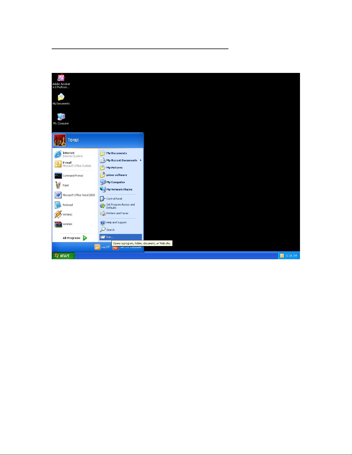
1. Click Start and click Run
24
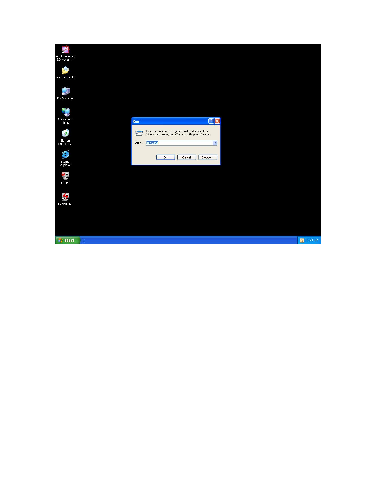
2. Type “Command” in the run prompt, Click OK
25
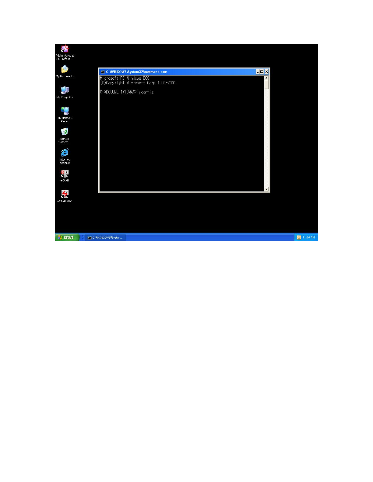
3. A Dos Command prompt will open. Type in “ipconfig” and press Enter
26
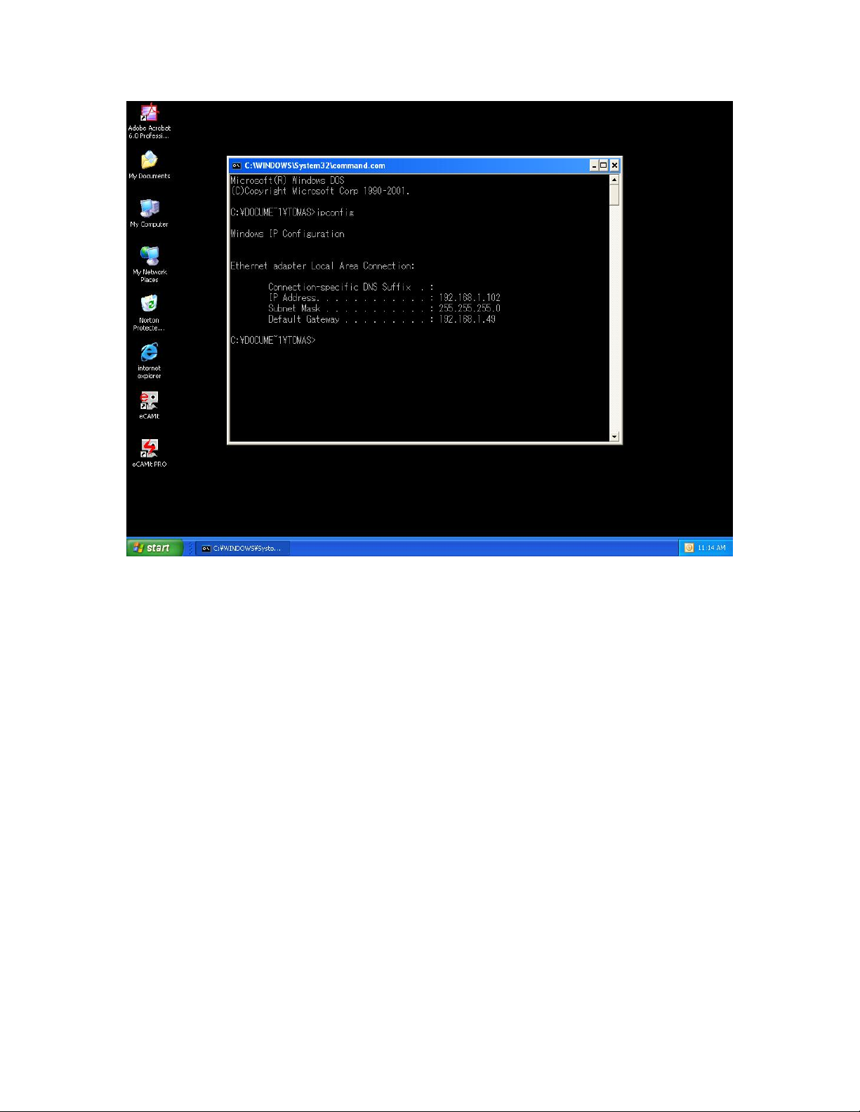
4. Your IP Address will Display, along with the Subnet Mask, and your
Gateway
27
Setting Static IP Address
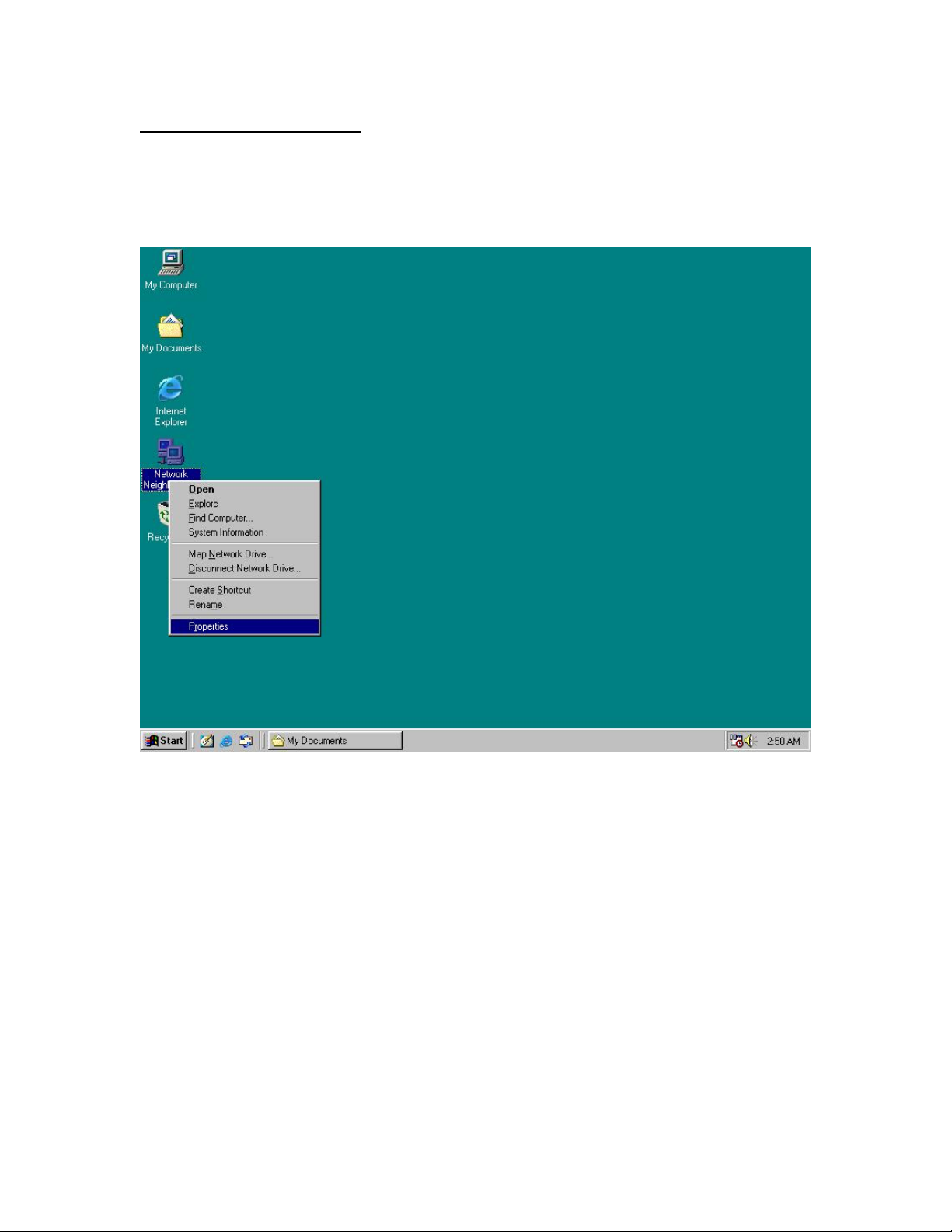
Part 1: Windows 98 SE / ME
1. Right Click on “Network Neighborhood” and click “Properties”
28
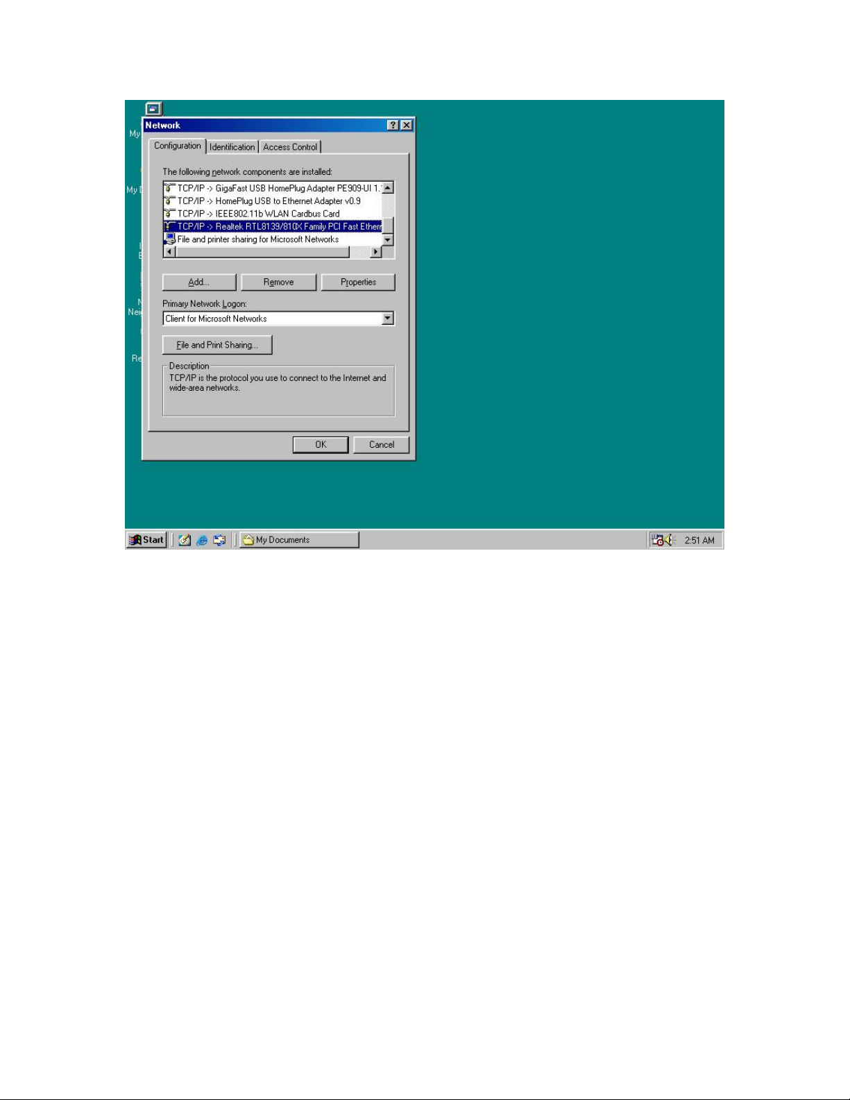
2. Click on “TCP/IP” for the network adapter you want to set IP addresses
for
29
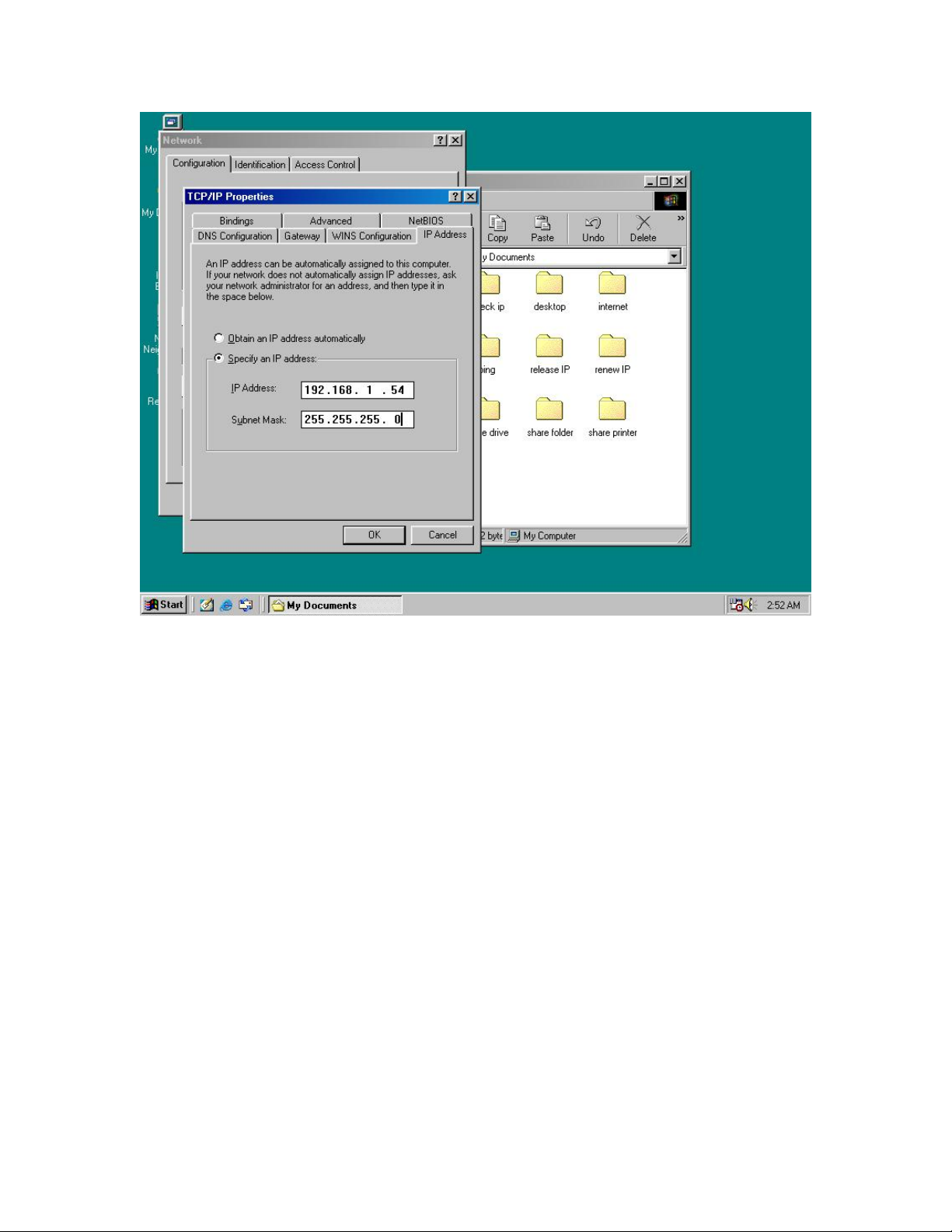
3. Click on “Specify an IP address” Type in the IP Address you wish to use.
(192.168.XXX.XXX is very standard for home networks) Click on the
Subnet mask, and if you know the subnet mask you want to use, type it in,
otherwise it should fill in with “255.255.255.0” which is very standard for
subnet masks.
30

4. Click on the “Gateway” tab, and add in your gateway IP address.
31

5. Click on the “DNS Configuration” tab, and add in your DNS server IP
address. Click OK button when you done.
32

5. To save the changes you must restart, so click “YES”
33

Part 2: Windows 2000 / XP
1. Right click My Network Places and click Properties.
34

2. Find and “Double Click” the Local Area Connection for the Network
adapter you want to Set IP’s for.
35

3. Click Properties
36

4. Click(Highlight) “Internet Protocol (TCP/IP)” and click “Properties”
37

5. Click “Use the following IP address” Type in the IP Address you wish to
use. (192.168.XXX.XXX is very standard for home networks) Click on the
Subnet mask, and if you know the subnet mask you want to use, type it in,
otherwise it should fill in with “255.255.255.0” which is very standard for
subnet masks. Click on the Default gateway and fill that in. If you know
the DNS you are going to use, fill it in otherwise leave it blank. Then click
OK.
38

6. To check that everything is Correct, Click on “Support” and the
information you typed in should appear.
39

Release and Renew an IP address
Part 1: Windows 98 SE / ME
1. Click Start, then click Run
40

2. Type “winipcfg” and click OK
41

3. Select the Network adapter you want to release IP’s for.
42

4. Click “Release”
43

5. Your IP Address should turn to 0.0.0.0
44

6. If you Click Release, and an error saying “IP Address for adapter is
already released” then you do not need to release any more, Try
“Renewing your IP”
45

Part 2: Windows 2000 / XP
1. Click Start, then click Run
46

2. Type Command and click OK
47

3. Type “ipconfig /release” and press Enter
48

4. Your IP Address should turn to 0.0.0.0 . To Renew your address check
Renewing IP Address.
49

5. If you receive an Error “The operation failed as no adapter is in the
state permissible for this operation.” Then you might need to set your
Network adapter to obtain your “IP Address Automatically”.
50

Appendix C: Local Area Network
Sharing Files (
Part 1: Sharing Folders
Windows 98SE / ME / 2000 / XP)
1. Double click “My computer” on your O/S desktop
51

2. Double Click the Drive where the folder that you want to share is located.
52

3. Right Click on the folder you want to share, and click “Properties”
53

4. Click “If you understand the risk but still want to share the root of the
drive, click here”
54

5. Click “Share this folder on the network” and specify the name you want
the folder to be seen as on the network.
55

6. A Hand should appear under the folder you wanted to share letting you
know that it is shared on the network.
56

Part 2: Sharing Drives
1. Right click on “My Computer” and click “Properties” on your O/S
desktop
57

2. Right click on the drive you want to share and click “Properties”
58

3. click on the Sharing tab “If you understand the risk but still want to
share the root of the drive, click here”
59

4. Click on “Share this folder on the network” and specify what you want
your shared folder to be viewed as.
60

5. A hand should appear under the drive you wanted to share. This lets you
know that it is shared on your network
61

Part 3:
Accessing Other Computers Shared Files
1. Find the IP Address of the computer you want to access(Look at Check
IP)
2. Click Start, and then click Run
62

3. Type “\\” and the IP address of the computer you want to access. (Format
is “XXX.XXX.XXX.XXX”)
63

4. All the files that the computer you are trying to access will open in a new
window.
64

5. An Alternate way to do the same thing is to find the Computer Name of the
computer you are trying to access. And typing “\\______” with the
computer name in the blank
65

6. All the files that the computer you are trying to access will Open in a new
window.
66

Sharing Printers (Windows 98SE / ME / 2000 / XP)
Part 1: Setup print server
1. Click “Start” and click ‘Printers and Faxes”
67

2. Right click on the printer you want to share and click “Properties”
68

3. Click the “Sharing” tab, and click “Share the printer” then specify the
name that you want the printer to be seen as on the network. Then click
“OK”
69

4. A hand should appear under the printer you want to share.
70

Part 2: Network Printer Installation
1. Click Start and click on Printers and Faxes.
71

2. The Printers and Faxes window should open, on the left side there
should be an Add a Printer button under Printer Tasks. Click on Add
a Printer
72

3. The Add Printer Wizard should appear, click Next to proceed
73

4. Select “A network printer, or a printer attached to another
computer” and click Next
74

5. Click “Browse for a printer”, unless you know the computer name (or
IP address) of the printer, and the exact printer name. Or the printer is
at a location that can be connected to through the internet. And click
Next
75

6. Browse through your network and select the printer that you want to
add, Highlight it, and click Next
76

7. Click Yes to proceed
77

8. Unless you want this to be your default printer, click NO, otherwise
click YES and click Next
78

9. Click Finish to finish the network installation
79

10. The printer should now be installed on your computer.
**Note** You may need to install drivers for the printer you want to install, so
make sure you have them available before trying to install any printer.
80

Access Internet
Part 1: Windows 98SE / ME
1. Double Click Internet Explorer
81

2. The Internet Connection Wizard Should open(If this does not open and
Internet Explorer Opens up, skip to Section 7) Click “I want to set up my
Internet Connection Manually, or I want to connect through a local
area network(LAN)” click Next
82

3. Click “I connect through a local area network(LAN)” Click Next
83

4. Click “Automatic discovery of proxy server(recommended)” Click next
84

5. Unless you want to setup your Email (you can do this separately later)
Click NO, and click ‘Next’.
85

6. Click the box, and click Finish
86

7. You should be on the internet, If a website does not occur Try to Release
IP, then Renew IP, and try to Ping your gateway.
87

Part 2: Windows 2000 / XP
1. Double Click on Internet Explorer
88

2. The New Connection Wizard might open(If this does not happen, skip to
Step 7) Click Next
89

3. Click “Connect to the Internet” and click Next
90

4. Click “Set up my connection manually”
91

5. Click “Connect using a broadband connection that is always on”
92

6. Click Finish
93

7. You should be on the internet, If a website does not occur Try to Release
IP, then Renew IP, and try to Ping your gateway.
94

Appendix D: Glossary
Default Password
A password set by the manufacturer that is unique to each device and is used to
Generate a Default Encryption Key (DEK). The DEK is used only for the purpose
of encrypting management commands that change the NEK so that the NEK is
never sent in the clear over the powerline.
DHCP
Dynamic Host Configuration Protocol is a method in which IP addresses are
assigned by server dynamically to the clients on the network. DHCP is used for
Dynamic IP Addressing and requires a dedicated DHCP server on the network.
Encryption Key (EK)
64-bit pattern generated by a key derivation function. An EK is used in an
encryption algorithm to add security to transmissions between HomePlug devices
in a logical network.
Ethernet
Ethernet is a 10/100Mbps network that runs over dedicated home/office wiring.
Users must be wired to the network at all times to gain access.
Gateway
A gateway is a hardware and software device that connects two dissimilar
systems, such as a LAN and a mainframe. In Internet terminology, a gateway is
another name for a router. Generally a gateway is used as a funnel for all traffic
to the Internet.
IEEE
The Institute of Electrical and Electronics Engineers. The IEEE describes itself as
“the world’s largest technical professional society—promoting the development
and application of electro technology and allied sciences for the benefit of
humanity, the advancement of the profession, and the wellbeing of our
members.”
Local Area Network (LAN)
A LAN is a group of computers, each equipped with the appropriate network
adapter card connected by cable/air, that share applications, data, and
peripherals. All connections are made via cable or wireless media, but a LAN
does not use telephone services. It typically spans a single building or campus.
Logical Network
Two or more HomePlug devices that share a common Network Encryption Key
(NEK) and that communicate with encrypted transmissions.
95

Network
A network is a system of computers that is connected. Data, files, and messages
can be transmitted over this network. Networks may be local or wide area
networks.
Network Password
A password set by the user that generates the NEK and defines the user’s logical
network.
RJ-45
A connector similar to a telephone connector that holds up to eight wires, used
for connecting Ethernet devices.
Router
Protocol-dependent device that connects subnet works together. Routers are
useful in breaking down a very large network into smaller sub networks; they
introduce longer delays and typically have much lower throughput rates than
bridges.
Powerline Networking
Data transmission over powerlines.
Password
Sequence of characters that serves as input to a key derivation function that
generates an Encryption Key (EK).
Protocol
A protocol is a standardized set of rules that specify how a conversation is to
take place, including the format, timing, sequencing and/ or error checking.
Static IP Addressing
A method of assigning IP addresses to clients on the network. In networks with
Static IP address, the network administrator manually assigns an IP address to
each computer. Once a Static IP address is assigned, a computer uses the same
IP address every time it reboots and logs on to the network, unless it is manually
changed.
Transmission Control Protocol / Internet Protocol (TCP/IP)
TCP/IP is the protocol suite developed by the Advanced Research Projects
Agency (ARPA). It is widely used in corporate Internet works, because of its
superior design for WANs. TCP governs how packet is sequenced for
transmission the network. The term “TCP/IP” is often used generically to refer to
the entire suite of related protocols.
96

Wide Area Network (WAN)
A WAN consists of multiple LANs that are tied together via telephone services
and / or fiber optic cabling. WANs may span a city, a state, a country, or even the
world.
Appendix E: Product Specification
Computer Interface IEEE802.3
Network Interface HomePlug Powerline
10Base-T: UTP CAT.3,4,5
Cable Connection:
100Base-TX: UTP CAT.5
Installation: Plug-and-Play
LED Indicators: PWR: Power HP: HomePlug ACT Link / Act, Eth: Link / Act
Certifications: HomePlug Powerline Specification 1.0
Operating
Temperature:
Humidity: 5% - 90%
Certifications:
HomePlug Configuration
Utility Support:
Warranty: Three Year & Free Technical Support (US Only)
0。 – 40。C
FCC Class B / CE Mark
Windows 98SE/ ME/ 2000/ XP
97

Appendix F: Warranty Info.
Limited Warranty
Limited Warranty Statement: GigaFast Ethernet Solutions Inc. ("GFE") warrants its products to be free from defects in
workmanship and materials, under normal use and service, for the applicable warranty term. All GFE products carry a standard
limited warranty from the date of purchase from GFE or its Authorized Reseller. GFE may, at its own discretion, repair or replace
any product not operating as warranted with a similar or functionally equivalent product, during the applicable warranty term.
All products that are replaced become the property of GFE. Replacement products may be either new or reconditioned. Any
replaced or repaired product carries either a 30-day limited warranty or the remainder of the initial warranty, whichever is longer.
GFE is not responsible for any custom software or firmware, configuration information, or memory data of Customer contained
in, stored on, or integrated with any products returned to GFE pursuant to any warranty. Products returned to GFE should have
any customer-installed accessory or add-on components, such as expansion modules, removed prior to returning the product
for replacement. GFE is not responsible for these items if they are returned with the product.
Customers must contact GFE for a Return Material Authorization number prior to returning any product to GFE. Proof of
purchase may be required. Any product returned to GFE without a valid Return Material Authorization (RMA) number clearly
marked on the outside of the package will be returned to custome r at customer’s expense. For warranty claims within North
America, please call our toll-free customer support number at (888) GFE-6788/(888) 433-6788. Customers are responsible for
all shipping charges from their facility to GFE. GFE is responsible for return shipping charges from GFE to customer.
WARRANTIES EXCLUSIVE: IF A GFE PRODUCT DOES NOT OPERATE AS WARRANTED ABOVE, CUSTOMER'S SOLE
REMEDY SHALL BE REPAIR OR REPLACEMENT OF THE PRODUCT IN QUESTION, AT GFE’S OPTION. THE
FOREGOING WARRANTIES AND REMEDIES ARE EXCLUSIVE AND ARE IN LIEU OF ALL OTHER WARRANTIES OR
CONDITIONS, EXPRESS OR IMPLIED, EITHER IN FACT OR BY OPERATION OF LAW, STATUTORY OR OTHERWISE,
INCLUDING WARRANTIES OR CONDITIONS OF MERCHANTABILITY AND FITNESS FOR A PARTICULAR PURPOSE.
GFE NEITHER ASSUMES NOR AUTHORIZES ANY OTHER PERSON TO ASSUME FOR IT ANY OTHER LIABILITY IN
CONNECTION WITH THE SALE, INSTALLATION, MAINTENANCE OR USE OF ITS PRODUCTS. GFE SHALL NOT BE
LIABLE UNDER THIS WARRANTY IF ITS TESTING AND EXAMINATION DISCLOSE THE ALLEGED DEFECT IN THE
PRODUCT DOES NOT EXIST OR WAS CAUSED BY CUSTOMER'S OR ANY THIRD PERSON'S MISUSE, NEGLECT,
IMPROPER INSTALLATION OR TESTING, UNAUTHORIZED ATTEMPTS TO REPAIR, OR ANY OTHER CAUSE BEYOND
THE RANGE OF THE INTENDED USE, OR BY ACCIDENT, FIRE, LIGHTNING, OR OTHER HAZARD.
LIMITATION OF LIABILITY: IN NO EVENT, WHETHER BASED IN CONTRACT OR TORT (INCLUDING NEGLIGENCE),
SHALL GFE BE LIABLE FOR INCIDENTAL, CONSEQUENTIAL, INDIRECT, SPECIAL, OR PUNITIVE DAMAGES OF ANY
KIND, OR FOR LOSS OF REVENUE, LOSS OF BUSINESS, OR OTHER FINANCIAL LOSS ARISING OUT OF OR IN
CONNECTION WITH THE SALE, INSTALLATION, MAINTENANCE, USE, PERFORMANCE, FAILURE, OR
INTERRUPTION OF ITS PRODUCTS, EVEN IF GFE OR ITS AUTHORIZED RESELLER HAS BEEN ADVISED OF THE
POSSIBILITY OF SUCH DAMAGES.
SOME STATES DO NOT ALLOW THE EXCLUSION OF IMPLIED WARRANTIES OR THE LIMITATION OF INCIDENTAL OR
CONSEQUENTIAL DAMAGES FOR CONSUMER PRODUCTS, SO THE ABOVE LIMITATIONS AND EXCLUSIONS MAY
NOT APPLY TO YOU. THIS WARRANTY GIVES YOU SPECIFIC LEGAL RIGHTS, WHICH MAY VARY FROM STATE TO
STATE. NOTHING IN THIS WARRANTY SHALL BE TAKEN TO AFFECT YOUR STATUTORY RIGHTS.
* GFE will provide warranty service for one year following discontinuance from the active GFE price list. Under the limited
lifetime warranty, ternal and external power supplies, fans, and cables are covered by a standard one-year warranty from in
date of purchase.
Appendix G: Contact Information
Gigafast Technical Support Department
Hours of Operation:
Monday thru Saturday 8AM - 8PM
Excluding Holidays
(888) GFE-6788 or (888) 433-6788
techsupp@gigafast.com
98
 Loading...