


16-port Flexible Switch Installation Guide
We make no warranties with respect to this documentation and disclaim any implied
warranties of merchantability, quality, or fitness for any particular purpose. The
information in this document is subject to change without notice. We reserve the right to
make revisions to this publication without obligation to notify any person or entity of
any such changes.
Trademarks or brand names mentioned herein are trademarks or registered trademarks
of their respective companies.
Installation Guide
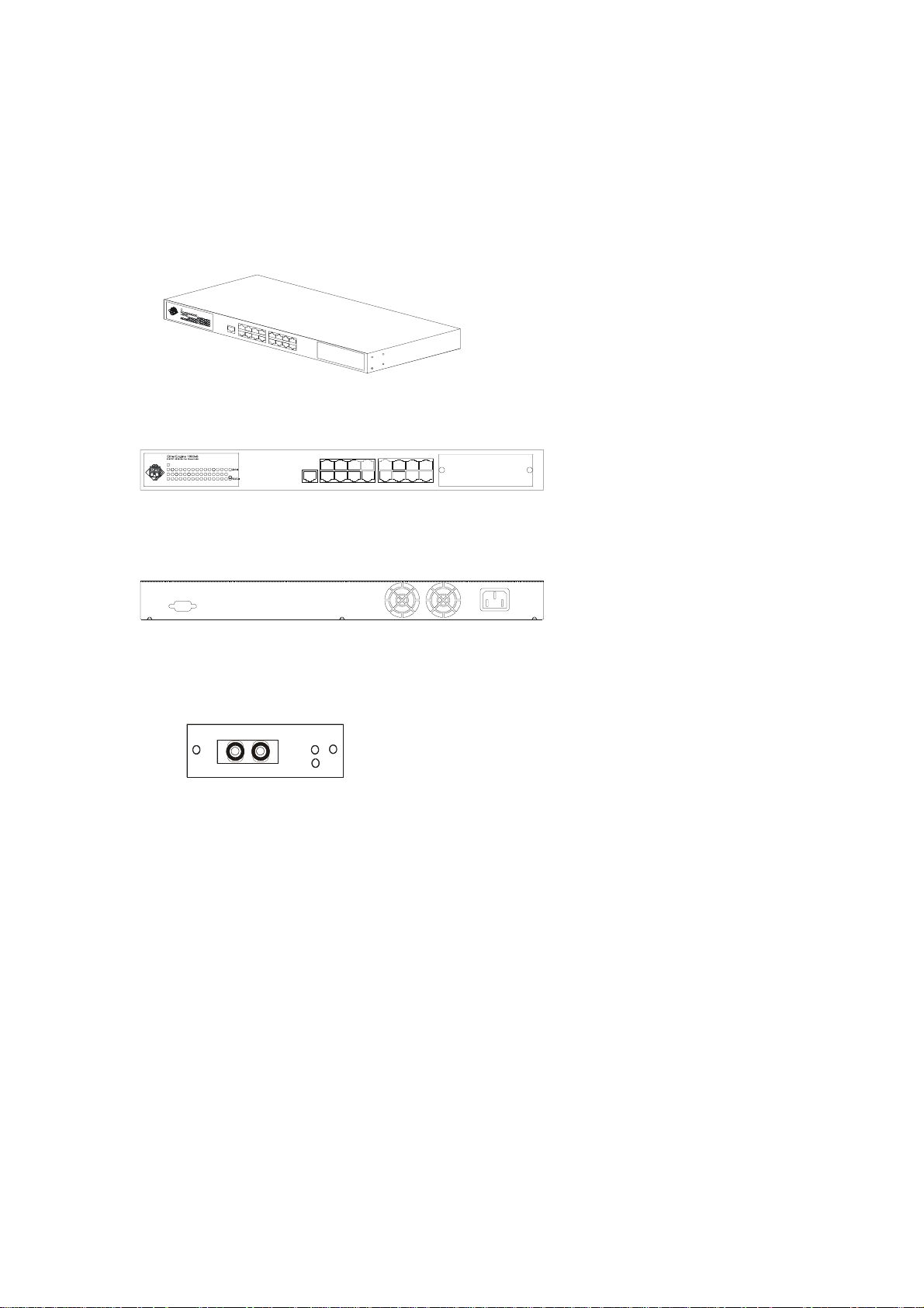
16-port 10/100Mbps Nway Ethernet Switching HUB
Sixteen 10/100Mbps RJ45 TX ports + one extension module port / with portbase configuration and VLAN, Trunking functions.
POWERPOWER
Front View:
Indicator Panel MDI Port MDI-X Ports Extension Module
POWER
100M
1614131211 1589673412 510
Rear View:
Console Port Cooling Fan Power Socket
The Extension Modules:
1*100BaseFX SC/ST

Contents
Installation Guide
1. Introduction
1.1 Package Contents
1.2 Installation Procedure
2. Where to Place the Switch
2.1 Placing the Switch onto a Desk or Shelf
2.2 Mounting the Switch onto a Rack
3. Configure The Switch
3.1 Configure the Switch From the Console Port
3.2 Add Extension Ports with Module
4. Configure The Network Connection
4.1 Connecting Devices to the Switch
4.2 Trunking to Another Ethernet Switch
4.3 Connecting to Another Ethernet Switch/Hub (Non-Trunking)
4.3.1 MDI to MDX Connect
4.3.2 MDX to MDX Connect
4.3.3 100Base-FX to 100Base-FX Connect
4.4 Application
5. LED Conditions Defined
5.1 LEDs Defined
6. Troubleshooting
6.1 Resolving no Link Conditions
6.2 Q&A
Appendix A – Product Specifications
Appendix B – Cable Specifications
Appendix C – Electro-magnetic and Safety Compli ances
Appendix D – Warranty
1. Introduction
g
This 16-port Switching Hub is flexible 10/100Mbps Fast Ethernet switching HUB.
One extension module port is designed for 100Base-Fx extension. This module
clued be 1*SC/ST ports or module and the switch will become a 17 ports switching
hub. This flexibility is helpful for users to extend their network connection.
There is a console port at the rear panel of the 16-port switching hub. User can setup
per-port 10/100Mbps, Half/Full duplex configuration from the console port. The
VLAN and Trunking functions of the 16-port switching hub is also setup from the
console port. Users can setup VLAN groups for network management or user can setup
trunking connection for switch-to-switch connection with faster bandwidth. This
switching HUB can auto-sense the operation speed (10Mbps or 100Mbps) and operation
mode (full or half duplex)*. There is a clear indicator panel for Link/Act, 100M speed
and Full-duplex/Collision of each port for network status monitor.
Notes: If 100BaseFX SC/ST connectors, the operation speed is 100Mbps and the operation mode is full duplex.
*
And the operation mode can be changed to half duplex from the console port.
1.1 Package Contents
One 16-port 10/100Mbps Ethernet Switching Hub
One AC power Cord
Two rack-mount kits and screws
Four self-adhesive rubber foot pads
This installation guide
1.2 Installation Procedure
Select Switch
Location
Section 4
Configure The
Network Connection
Section 3
Configure The
Switch (O ption)
Section 5,6
Tr oubleshootin
Section 2
2. Where To Place the Switch
This 16-port Switch can be placed on a flat surface (your desk, shelf or table) or
mounted onto a rack.
Place the 16-port Switch at a location with these connection considerations in mind:
The switch configuration does not break the rules as specified in section 4.
The switch is accessible and cables can be connected easily to it.
The cables connected to the switch are away from sources of electrical
interference such as radio, computer monitor, and light fixtures.
There is sufficient space surrounding the hub to allow for proper ventilation (the
hub may not function according to specifications beyond the temperature range
of 0 to 40 degrees C).
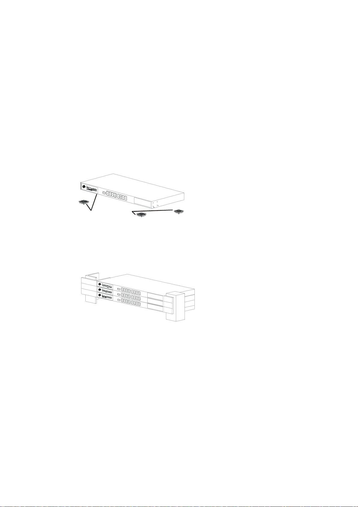
2.1 Placing The Switch on a Desk or Shelf
a. Stick the self-adhesive rubber foot pads (that come with this package) on each of the
4 concave spaces located on the bottom of the first hub.
b. Place the first hub on a firm flat surface where you want to install the stack.
c. Repeat step a. for each hub before stacking them. The rubber foot pads cushion the
hub against shock or vibrations and provide space between each hub for ventilation.
POWERPOWER
Attach the 4 rubber feet to the bottom
before placing on a shelf or table.
2.2 Mounting The Switch Onto a Rack
1. Use the brackets and screws supplied in the rack mounting kit.
2. Use a cross-head screwdriver to attach the brackets to the side of the bub.
3. Position the switch in the rack by lining up the holes in the brackets with the
appropriate holes on rack, and then use the supplied screws to mount the hub onto the
standard EIA 19-inch rack.
POWER
POWER
POWER
3. Configure the Switch
3.1 Configure the Switch from the Console Port
〔1〕Setup Hardware and Software for configuration
〔Hardware setup
Hardware setup〕
Hardware setupHardware setup
Connect from the console port (at rear panel) of the Switch to COM
port of PC with the RJ45-DB9 adapters and one network cable, or
standard RS232 cable.
〔Soft
Software setup
ware setup〕
SoftSoft
ware setupware setup
1. PC is running Win95/98/NT.
2. Start ->Program ->Accessory ->Terminal. Execute”Hypertrm” program.
3. If the connection file has been created, cancel the new connection request and
open the connection file. If the connection file has not been created, create a
new connection named “SW16F” ->Select COM port of PC ->Set COM port
parameters as “Baud Rate: 9600, Data Bits: 8, parity Check: None, Stop Bit: /,
Flow Control: None” Then OK.
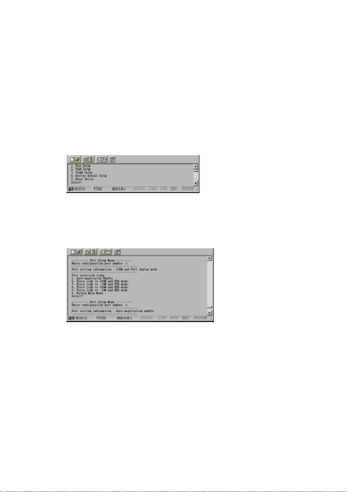
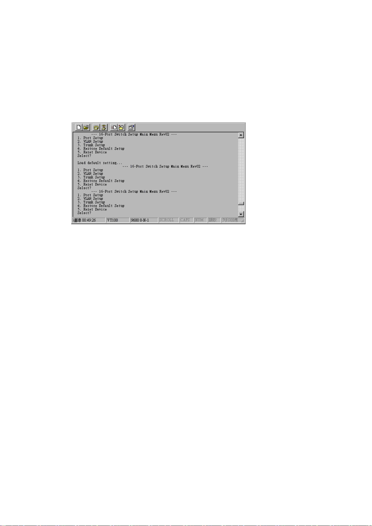
4. Power on the Switch and the setup console will appear as follow:
〔2〕Configure Connection Ports of the Switch
1. Users can enable/disable the auto-negotiation function of the
connection ports with this function. If the auto-auto-negotiation
is disabled, users can set the connection speed, full/half duplex
of the connection ports. The default setting is auto-negotiation
enable.
2. Follow the direction in the setup menu to setup the configuration
of the connection ports.
3. The indicators of the display panel of the Switch may ON/OFF depending on
the setting of the ports in this function when the cables are link connected.
Notes: If the connection ports are 100Base-FX SC/S T ports, the auto-
negotiation function of the ports will be al ways disable. User can set
the 100Base-FX ports to full/half duplex and enable/disable flow control in this function.

〔3〕Setup VLAN Groups of the Switch
1. Enter the VLAN setup function in the setup console as follow.
2. All of the connection ports are in the same VLAN group default.
3. Users can modify/add/remove connection ports to/from VLAN groups.
4. Select group number first.
5. Select the port number to be added or removed.
6. Repeat Step 5 to complete the setup of one VLAN group.
7. Repeat Step 4~5 to complete the setup of another VLAN group.
8. Quit to the main menu.
Notes: Data will only be forwarded to ports in the same VLAN group. Data will not
be forwar ded to ports in dif ferent VLAN groups, just like they were not
connected together. The factory default setting of the switch is all ports are
in the same VLAN group.
〔4〕Setup Trunking Connection of the Switch
1. Enter the Trunking setup function in the setup console as follow.
2. The VLAN and Trunking functions of the Switch cannot work at the same Time.
If Trunking function is enabled, the VLAN function will be disabled.
3. User may see current trunk connection configuration. Because there may be two
trunk connections for the switch, please select one of them to setup.
4. Set how many ports used for the trunk connection.
5. After setup, user can quit and save the setting.
6. Then user may create the trunk connection-connecting crossover cables from the
trunking ports of thw Switch to another switching hub. These ports on the other
switching hub must be Trunking ports. Please refer to section on the other
switching hub must be Trunking ports. Please refer to section 4.2 for creating
trunk connection.
〔5〕Setup the Switch to Default Setting
1. Enter the Default Setting function in the setup console.
2. Recover to default setting.
〔6〕Reset Device of the Switch
1. Enter the Reset Device setup function in the setup console.

3.2 Add Extension Ports with Module
There is module port on the rear panel of the Switch. User and add one more
100Base-FX SC/ST ports from it and the Switch will become a 17 ports Switch. (Please
refer to Installation Guide at the first page of this user’s manual.) User can add the
module for their networking environment.
1.The module is fixed on the Switch with two screws.
2. Power off the Switch before adding the module.
3. Turn the screws counterclockwise with fingers or screw deive to loosen the module
cover.
4. Remove the module cover when it is loosened.
5. Slide the new module into the module port.
6. Turn the screws clockwise with fingers or screw drive to fix the module on the switch.
〔Warning:〕
is off. Otherwise, the module and Switch may be damaged.
Before remove or plug the module on the Switch, please make sure the power
4. Configure the Network Connection
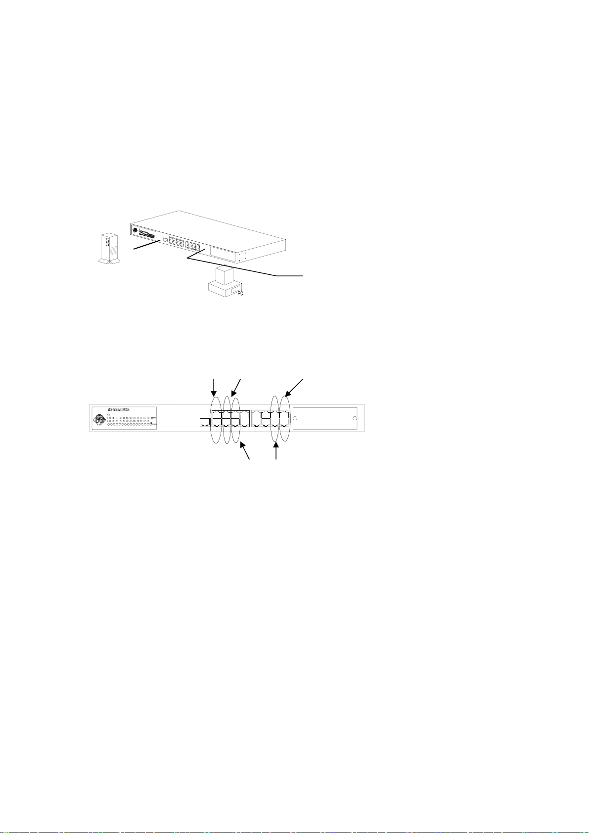
4.1 Connecting Devices to the Switch
Connection Guide lines:
● Use Category 3 or 5 twisted-pair Ethernet cable when connecting 10BaseT devices to
the hub (cable pin assignments defined in Appendix A)
● Use Category 5 (straight-through) twisted-pair Ethernet cable when connecting
100BaseTX devices to the hub (cable specifications are defined in Appendix B)
● Always limit the cable distance to 100 meters (328 ft) as defined by IEEE
specification.
● If 100Base-FX connections the maximum cable length is 2Km (1.24miles).
POWERPOWER
FS
100BASETX:
Cat-5 Twisted-pair cable
Max. 100m (328 feet)
10BASET:
Cat-3,4,5 Twisted-pair cable
Max. 100m (328 feet)
4.2 Trunking to Another Ethernet Switch
1.Two trunking connections maximum is allowed for this switch. The first trunking
connection can be built on Port(1,9), or Port(1,2,9,10), or Port(1,2,3,9,10,11). The
other trunking connection can be built on Port(7,15), or Port(7,8,15,16), or
Port(7,8,15,16, extension module ports). Please refer to following front panel about
the trunking connection.
Port 1,9 port 1,2,9,10
POWER
100M
1614131211 1589673412 510
Port 1, 2,3,
9,10,11
The total bandwidth is 400Mbps if two ports are used for trunking connection.
The total bandwidth is 800Mbps if four ports are used for trunking connection.
The total bandwidth is 1200Mbps if six ports are used for trunking connection.
Port 7,8,15,16
Port 7,15

2. Connect from the trunking ports of the Switch to another Ethernet switch with Cat.5
crossover cables and the connection ports of the other switch must be trunking ports.
3.After making the connection, please refer to Section 3.1 to setup the trunking function
of the switch
The 16-port Switch
Switching Hub
POWERPOWER
R
R
E
E
W
W
O
O
P
P
From: Port 1,2.9,10
Cat. 5 Crossover cable
Max. 100 meter (328 feet)
TO: MDI-X ports
(Trunking ports)
4.3 Connecting to Another Ethernet Switch/Hub
(Non-Trunking)
The Switch can be connected to existing 10Mbps or 100Mbps hubs/switches. The
switch/hub to switch/hub connection guidelines are as follows:
4.3.1 MDI to MDX Connect – Use normal “Straight Through” TP Cable when
connecting the Switch MDI port to another standard port at the other hub.
POWERPOWER
From: MDI port
Straight-Through cable
Max. 100m (328 feet)
4.3.2 MDX t o MDX Connect – Use crossover TP cable when connecting the Switch
device port to another standard port at the other hub.
POWERPOWER
Cross-over cable
Max. 100 (328 feet)
4.3.3 100Base-FX to 100Base-FX Connect – If the 100Base-FX SC/ST extension
module is added to the Switch, users can connect to the 100Bse-FX SC/ST ports of
another switch/hub/adapter with fiber optic cables. The maximum cable length is
2Km (1.24miles)
POWERPOWER
POWERPOWER
To: MDX port
POWERPOWER
To: MDX port From: MDI port
POWERPOWER
Fiber Optic cable
Max. 2Km (1.24miles)
To: 100Base-FX SC/ST port

4.4 Application
An Ethernet switch can be used to overcome the hub to hub connectivity limitations
as well as improve overall network performance. Switches make intelligent decisions
about where to send network traffic based on the destination address of the packet. As
a result, the switch can significantly reduce unnecessary traffic.
The example below demonstrates the switch ability to segment the network. The
number of nodes on each segment is reduced thereby minimizing network contention
(collisions) and boosting the available bandwidth per port.
User can setup VLAN of the 16-port Switch for network management. User can also
setup Trunking of the 16-port Switch for faster trunk connection between switches.
Please refer to Section 3.1 for the configuration of the 16-port Switch.
POWERPOWER
FS
FS
P
P
O
O
R
R
W
W
E
E
1
0
0
B
a
s
e
Dual Speed Hub
The 16-port Switch
-
F
X
c
o
n
n
e
c
t
i
o
n
Switch at Remote
POWERPOWER
(
2
K
m
m
a
x
.
)
POWERPOWER
Dual Speed Hub
Power User
Workgroup
Workgroup

5. LEDs Defined
5.1 LEDs Defined
The 16-port Switch LEDs provide useful information about the hub and the status of
all individual ports.
100M
4321 765 9108
LED STATUS CONDITION
Power ON Hub is receiving power
Link / Act
100M
FDX / Col
ON Port has established a valid link
Flashing Data packets being received or sent
ON The connection speed is 100Mbps
OFF The connection speed is 10Mbps
ON The connection is Full Duplex
Flashing Packet collisions occurring. A low level of
collision is a part of normal Ethernet Operation
141311 12 1615

6. Troubleshooting
6.1 Resolving No Link Conditions
The possible causes for a no link LED status are as follow:
◙ The attached device is not powered on
◙ The cable may not be the correct type or is faulty
◙ The installed building premise cable is faulty
◙ The switch port may be faulty
Note: Because Port 16 MDI-X port and the MDI port share the same components, if
the port 16 MDI-X port is used, please don’t use the MDI port. Or, if the MDI
port is used, please don’t use the Port 16 MDI-X port.
6.2 Q&A
1. Computer A can connect to Computer B, but cannot connect to Computer C
through the 16-port Switch.
◘ Computer A and Computer C may be in different VLAN groups. Please check
the VLAN setup from the Console port.
◘ The network device of Computer C may fail to work. Please check the link/act
status of Computer C on the LED indicator. Try another network device on this
connection.
◘ The network configuration of Computer C may be something wrong. Please
verify the network configuration on Computer C.
2. The trunk connection function fails to work.
◘ Please check the trunking cables are connected on trunking ports. (Please refer to
Section 4.2 for trunking connection).
◘ The connection ports on another switch must be trunking ports. Please check if
trunking switching ports are used on that switch.
◘ Because the connection ports on both sides are MDI-X ports, crossover cables
are needed for the trunk connection. Please check the cables. Cat5 is suggested.
◘ Please check the trunking setup from the Console port of the Switch to verify the
trunking function is enable. (Notes: VLAN will be disable when trunking is
enabled.)

3. The setup page os the Console port cannot appear.
◘ The COM port parameters are [Baud Rate: 9600, Data Bits: 8, Parity Bits: None,
Stop Bit: 1, Flow Control: None]. Please check the COM port property in the
Hypertrm program.
◘ Check the RJ45-DB9 adapters are connected well on the Console port of the
16-port Switch and COM port of PC.
◘ A straight-through TP cable is requested to connect the RJ45-DB9 adapters
together. Please check if the correct cable is used.
◘ Check if the COM of the PC is enabled.
4. How to configure the 16-port Switch in DOS?
◘ The “Hypertrm” is the terminal program in Win95/98/NT. Users can use any
other terminal programs in DOS/Unix/OS2… to configure the Switch. The user
interface is similar witch Hypertrm. Please refer to the user guide of that
terminal program. But the COM port parameters must be [Baud Rate: 9600,
Data Bits: 8, Parity Bits: None, Stop Bit: 1, Flow Control: None].
◘ PROCOMM and TELIX are DOS terminal program. Users can use these
programs to configure the Switch.

A. Product Specifications
Access Method CSMA/CD, 10Mbps or 100Mbps
Standards Conformance IEEE 802.3 10BASE-T, IEEE 802.3u 100BASE-TX,
Communication Rate 10/100Mbps on RJ-45 ports, (100Mbps on SC/ST ports)
Communication Mode Full/Half duplex
Media Supported 10BASE-T – 100 Ohm Category 3,4,5 twisted-pair
Indicator Panel LEDs for Power, Link/Act, Speed, FDX/Col.
Number of Ports Sixteen 10BASE-T/100BASE-TX RJ45 ports, One
MDI-X/MDI Selection Alternate Port
Dimensions 330mmx204mmx44mm (LxWxH)
Weight 1.7 Kg (3.74lb)
Certification CE Mark
Emissions FCC Class A / VCCI Class-I / CISPR Class A
Immunity IEC 1000-4-2/3/4
Power Consumption 22 Watts max.
Input Power Full range: 100 to 240V, 50 to 60 Hz
Temperature Standard Operating: 0 to 40˚C (32 to 104˚F)
Humidity 5% to 95% (Non-condensing)
Network Bridging Function Filtering, forwarding and learning
Switching Method Store-and-forward
Address Table 8K entries
Queue Buffer 512K Bytes Shared Buffer
Filtering/Forwarding Rate Line speed
VLAN Function Port-Base, 8 groups max., setup by Console
Trunking Function Two trunk connections allowed, 6 port/trunk max.
Console Port DB9 connector for RS-232 connection
(100Base-FX for the extension ports)
100BASE-TX – 100 Ohm Category 5 twisted-pair
(100Base-FX – Fiber Optic cable)
Module port,
One Console port
Storage: -40 to 70˚C (-40 to 158˚F)
(1.2Gbps max.), setup by Console

B. Cable Specification
Three different types of cable are specified for use on the 16-port Switch:
◎ Standard “straight through” cable
◎ hub to Hub “cross-over” cable
◎ Fiber Optic cable (if the extension SC/ST module ports are added)
Cable Schematics
Standard Straight-Through Cable
Hub / Switch side Adapter side
Pin# Pair# Pin# Pair#
1. RX+ White-Orange ------------------ 1. RX+ White-Orange
2. RX- Orange ------------------ 2. RX- Orange
3. TX+ White-Green ------------------ 3. TX+ White-Green
4. Not Used Blue ------------------ 4. Not Used Blue
5. Not Used White-Blue ------------------ 5. Not Used White-Blue
6. TX- Green ------------------ 6. TX- Green
7. Not Used White-Brown ------------------ 7. Not Used White-Brown
8. Not Used Brown ------------------ 8. Not Used Brown
Hub-to-Hub Cross-Over Cable
Hub / Switch side Hub / Switch side
Pin# Pair# Pin# Pair#
1. RX+ White-Orange ------------------ 1. TX+ White-Green
2. RX- Orange ------------------ 2. TX- Green
3. TX+ White-Green ------------------ 3. RX+ White-Orange
4. Not Used Blue ------------------ 4. Not Used Blue
5. Not Used White-Blue ------------------ 5. Not Used White-Blue
6. TX- Green ------------------ 6. RX- Orange
7. Not Used White-Brown ------------------ 7. Not Used White-Brown
8. Not Used Brown ------------------ 8. Not Used Brown

Cable Type and Use
Connection Speed Cable Type
Hub to Hub (or Switch) 10Mbps Cross-over, Cat-3,4,5 twisted pair
Hub to Hub (or Switch) 100Mbps Cross-over, Cat-5 twisted pair
Hub to Server or Workstation 10Mbps Straight-Through, Cat-3,4,5 Twisted pair
Hub to Server or Workstation 100Mbps Straight-Through, Cat-5 Twisted pair
Hub to Print Sever 10Mbps Straight-Through, Cat-3,4,5 Twisted pair
Hub to Print Sever 100Mbps Straight-Through, Cat-5 Twisted pair
C. Compliances
EMI Certification
FCC Class A Certification (USA)
Warning: This equipment generates, uses, and can radiate radio frequency energy and, if
not installed and used in accordance ith the instruction manual, may cause interference
to radio communications. It has been tested and fund to comply with the limits for a
Class A digital device pursuant to Subpart B of Part 15 of FCC Rules, which are
designed to provide reasonable protection against such interference when operated in a
commercial environment. Operation of this equipment in a residential area is likely to
cause interference, in which case the user, at his own expense, will be required to take
whatever measures are required to correct the interference.
Canada Department of Communications – Class A
This digital apparatus does not exceed the Class A limits for radio noise emissions from
digital apparatus as set out in the interference-causing equipment standard entitled
“Digital Apparatus”, ICES-003 of the Department of Communications.
VCCI Class-I Compliance (Japan)
この装置は、情報技術装置等電波障害自主規制協議会(VCCI)の基準
に基つくクラスA情報技術装置です。この装置を家庭環境で使用すると電波
妨害を引き起こすことがあります。この場合には使用者が適切な対策を講ずる
よう要求されることがあります。
Warning! Do not plug a phone jack connector in the RJ-45 port. This may damage this
device.
D. Warranty
We warrant to the original owner that the product delivered in this package will be free
from defects in material and workmanship for a period of warranty time from the date of
purchase from us or the authorized reseller. The warranty does not cover the product if it
is damaged in the process of being installed. We recommend that you have the company
from whom you purchased this product install it.
 Loading...