

GigaCom ATX-II User Reference And Installation Manual
GigaCom
ATX-II Digital Radio
Software Defined IDUTM /ODU
User Reference and Installation Manual
Document Number: MK-MAN-01 Rev: D
Date: August 10, 2007

MK-MAN-01 USA VERSION ATX-II Digital Radio
ATX-II Digital Radio Manual Dwg # MK-MAN-01; Revision Levels: D
Section Drawing No: REV Revised /
Released
Reason
MK-MAN-01 A SN Initial Release
MK-MAN-01 B SN GUI Update
MK-MAN-01 C SN ODU Update

ATX-II Digital Radio MK-MAN-01 USA VERSION
Table of Contents
1 SAFETY PRECAUTIONS............................................. ........ ... .... .... .... ... .... ........ .... ... .... .... .... ... .............1-1
2 SYSTEM DESCRIPTION.............................................. .... .... ... ........ .... ... .... .... .... ... .... ........ .... .... ............2-1
2.1 About This Manual..........................................................................................................................................2-1
2.2 Introduction.....................................................................................................................................................2-1
2.3 System Features...............................................................................................................................................2-4
2.4 Physical Description........................................................................................................................................2-5
2.4.1 Model Options...........................................................................................................................................2-6
2.4.2 Front Panel Indicators................................................................................................................................2-7
2.4.3 Front Panel Connections............................................................................................................................2-7
2.5 System Description........................................................................................................................................ 2-12
2.6 Consecutive Point Architecture....................................................................................................................2-15
2.7 Power Management....................................................................................................... ...... ..........................2-18
2.8 Network Management...................................................................................................................................2-18
3 INSTALLATION.....................................................................................................................................3-1
3.1 Unpacking........................................................................................................................................................3-1
3.2 Notices...............................................................................................................................................................3-2
3.3 PRE-INSTALLATION NOTES ..................................................................................................................... 3-2
3.3.1 Back-to-Back Bench Testing.....................................................................................................................3-2
3.4 Overview of Installation and Testing Process...............................................................................................3-3
3.5 Site Evaluation........................................................... ....... ...............................................................................3-4
3.5.1 Preparing for a Site Evaluation..................................................................................................................3-5
3.5.2 Site Evaluation Process .............................................................................................................................3-6
3.5.3 Critical System Calculations......................................................................................................................3-8
3.5.4 Documenting a Site Evaluation...............................................................................................................3-10
3.6 Installation of the ATX-II Digital Radio......................................................................................................3-13
3.6.1 Installing the ATX-II Software Defined IDUTM...................................................................................... 3-13
3.6.2 Installing the ATX-II ODU .....................................................................................................................3-14
3.6.3 Routing the ODU/IDU Interconnect Cable..............................................................................................3-14
3.6.4 Connecting the SDIDUTM to the PC and Power Source..........................................................................3-31
4 SUMMARY SPECIFICATION................................................................................................................4-1
5 FRONT PANEL CONNECTORS...........................................................................................................5-1

MK-MAN-01 USA VERSION ATX-II Digital Radio
5.1 DC Input (Power) Connector .........................................................................................................................5-1
5.2 ATX-II Ethernet 100BaseTX Payload LOC Connector...............................................................................5-1
5.3 ATX-II Ethernet 100BaseTX CPT Connector..............................................................................................5-2
5.4 ATX-II SONET Pa yload Connector..............................................................................................................5-2
5.5 ATX-II STM-1 Payload Connector................................................................................................................5-3
5.6 ATX-II DS-3/E-3/STS-1 Payload Connector.................................................................................................5-3
5.7 NMS 10/100BaseTX LOC Connector............................................................................................................5-4
5.8 NMS 10/100BaseTX CPT Connector.............................................................................................................5-5
5.9 Alarm/Se rial Port Connector..........................................................................................................................5-6
5.10 ODU Connector...............................................................................................................................................5-7
5.11 T1- Channels 1-2 Connector...........................................................................................................................5-7
5.12 T1- Channels 3-16 Connector.........................................................................................................................5-8
6 APPENDIX.............................................................................................................................................6-2
6.1 Abbreviations & Acronyms............................................................................................................................6-2
6.2 Conversion Chart............................................................................................................................................6-5
ATX-II Digital Radio MK-MAN-01 USA VERSION
1 Safety Precautions
PLEASE READ THESE SAFETY PRECAUTIONS!
RF Energy Health Hazard
This symbol indicates a risk of personal injury due to radio frequency exposure.
The radio equipment described in this guide uses radio frequency transmitters. Do not allow
people to come in close proximity to the front of the antenna while the transmitter is operating.
The antenna will be professional installed on fixed-mounted outdoor permanent structures to
provide separation from any other antenna and all persons.
WARNING: RF Energy Exposure Limits and Applicable Rules for 6-38 GHz. It is recommended
that the radio equipment operator refer to the RF exposure rules and precaution for each
frequency band and other applicable rules and precautions with respect to transmitters, facilities,
and operations that may affect the environment due to RF emissions for each radio equipment
deployment site.
Appropriate warning signs must be properly placed and posted at the equipment site and access
entries.
Protection from Lightning
Article 810 of the US National Electric Department of Energy Handbook 1996 specifies that radio
and television lead-in cables must have adequate surge protection a t or near the point of entry to
the building. The code specifies that any shielded cable from an external antenna must have the
shield directly connected to a 10 AWG wire that connects to the building ground electrode.
Do not turn on power before reading GigaCom’s pro duct documentation. This device has a -48
VDC direct current input.
Protection from RF Burns
It is hazardous to look into or stand in front of an active antenna aperture. Do not stand in front of
or look into an antenna without first ensuring the associated transmitter or transmitters are

1-2 GigaCom Wireless - USA Version REV D
MK-MAN-01 USA VERSION ATX-II Digital Radio
switched off. Do not look into the waveguide port of an ODU (if applicable) when the radio is
active.
Risk of Personal Injury from Fiber Optics
DANGER: Invisible laser radiation. Avoid direct eye exposure to the end of a fiber, fiber cord, or
fiber pigtail. The infrared light used in fiber optics systems is invisible, but can cause serious
injury to th e eye.
WARNING: Never touch exposed fiber with any part of your body. Fiber fragments can enter the
skin and are difficult to detect and remove.

ATX-II Digital Radio MK-MAN-01 USA VERSION
2 System Description
2.1 About This Manual
This manual is written for those who are involved in the “hands-on” installation of the ATX-II
Digital Radio, such as installation technicians, site evaluators, project managers, and network
engineers. It assumes the reader has a basic understanding of how to install hardware, use
Windows® based software, and operate test equipment.
2.2 Introduction
The ATX-II family of digital radios provides high capacity transmission, flexibility, features, and
convenience for wireless digital communications networks. The ATX-II digital point-to-point
radios represent a new microwave architecture that is designed to address universal applications
for both PDH and SDH platforms. This advanced technology platform is designed to provide the
flexibility to customers for their current and future network needs.
The ATX-II radio family is based upon a common platform to support a wide range of network
interfaces and configurations. It supports links for 16 x E1/T1, DS-3/E-3/STS-1, 1/2 x 100BaseTX
Ethernet, and 1/2 x STM-1/OC-3. The radio family is spectrum and data rate scalable, enabling
service providers or organizations to trade-off system gain with spectral efficiency and channel
availability for optimal network connectivity. GigaCom’s digital radio family enables network
operators (mobile and private), government and access service provides to offer a portfolio of
secure, scalable wireless applications for data, video, and Voice over IP (VoIP).
The ATX-II digital radio family is composed of a Software Defined Indoor UnitTM (SDIDUTM)
and Outdoor Unit (ODU). The SDIDU
TM
is designed to be frequency independent, and the
ODU is designed to be capacity independent. The Software Defined IDU
TM
allows selection
for multiple capacity options, modulation types, radio frequency channels and transmit output
power levels to accommodate and adhere to world-wide regulatory and spectral efficiency
requirements. The companion ODU, mounted outdoors, can support frequency bands from
6 to 38 GHz.
The ATX-II SDIDU
TM
supports 1+0 and 1+1 protection and ring architectures in a single 1 RU
chassis. The modem and power supply functions are supported using easily replacable
plug-in modules. An additional feature of the SDIDU
TM
is provision for a second plug-in
modem/IF module to provide repeater or east/west network configurations.
The ATX-II Digital Radio includes integrated Operations, Administration, Maintenance, and
Provisioning (OAM&P) functionality and design features enabling simple commissioning when the
radio network is initially set up in the field at the customer’s premises. Furthermore, a highlight of
GigaCom’s radio products is scalability and the capability to support a ring-type architecture. This

2-2 GigaCom Wireless - USA Version REV D
MK-MAN-01 USA VERSION ATX-II Digital Radio
ring or consecutive point radio architecture is self-healing in the event of an outage in the link and
automatically re-routes data traffic, thereby ensuring that service to the end user is not
interrupted.
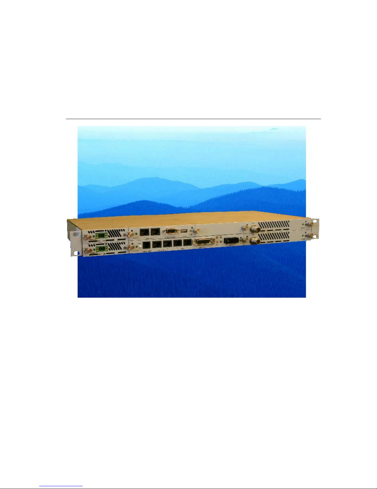
The overall architecture consists of a single 1RU rack mount Software Defined Indoor Unit
(
SDIDU
TM
) with a cable connecting to an Outdoor Unit (ODU) with an external antenna.
Figure 2-1. ATX-II SDIDUTM/ODU Architecture
Table 2-1 lists key features that ATX-II technology offers to those involved in the design,
deployment and support of broadband fixed wireless networks.
Table 2-1. Key Benefits and Advantages of ATX-II Digital Radios
Benefits Advantages to Providers/Customers Reference
Software Defined Indoor Unit (SDIDUTM)
Universal signal processing platform
Advanced Single Chip Modem ASIC
Integrated Forward Error Correction (FEC)
Powerful adaptive equalizer
Enables easy network interface options
and network capacity growth in the future.
Cost effective solution; simplifying product
logistics and overall product life cycle
costs. The flexibility reduces capital and
operating expenditures commonly
associated with field installation,
maintenance, training and spares.
Frequency independent and Scalable.
Software defined flexibility enables
selective modulation for spectral efficiency
and adherence to world-wide regulatory
emissions guidelines.
2.2 – 2.5

User Reference and Installation Manual 2-3
ATX-II Digital Radio MK-MAN-01 USA VERSION
Table 2-1. ATX-II Digital Radio Benefits and Advantages to Providers
(continued)
Benefits Advantages to Providers/Customers Reference
Easy to install units
Straightforward modular system enables
fast deployment and activation.
Carrier-class reliability.
Fast return on investment.
No monthly leased line fees.
3.1, 3.4, 3.6
Complete support of payload capacity with additional voice orderwire
Aggregate capacity beyond basic network
payload.
Scalable and spectrally efficient system.
Separate networks for radio
overhead/management and user payload.
Increases available bandwid t h of network.
Allows customer full use of revenue-
generating payload channel.
Lowers total cost of ownership.
2.2 – 2.5
Ring Architecture
Supports a ring (consecutive point)
configuration, thus creating a self-healing
redundancy that is more reliable than
traditional point-to-point networks.
In the event of an outage, traffic is
automatically rerouted via another part of
the ring without service interruption.
Ring/consecutive point networks can
overcome line-of-sight issues and reach
more buildings than other traditional
wireless networks.
Networks can be expanded by adding
more ATX-II Digital Radios or more rings
without interruption of service.
A separate management channel allows
for a dedicated maintenance ring with
connections to each ATX-II Digital Radio
on the ring.
Enables network scalability.
Increases deployment scenarios for initial
deployment as well as network expansion
with reduced line-of-sight issues.
Increases network reliability due to selfhealing redundancy of the network.
Minimizes total cost of ownership and
maintenance of the network.
Allows for mass deployment.
2.6
Table 2-1. ATX-II Digital Radio Benefits and Advantages to Providers
(continued)

2-4 GigaCom Wireless - USA Version REV D
MK-MAN-01 USA VERSION ATX-II Digital Radio
Benefits Advantages to Providers/Customers Reference
Adaptive Power Control
Automatically adjusts transmit power in
discrete increments in response to RF
interference.
Enables dense deployment.
Simplifies deployment and network
management.
2.7
Comprehensive Link/Network Management Software
A graphical user interface offers security,
configuration, fault, and performance
management via standard craft interfaces.
Suite of SNMP-compatible network
management tools that provide robust
local and remote management capabilities.
Simplifies management of radio network
and minimizes resources as entire network
can be centrally managed out of any
location.
Simplifies troubleshooting of single radios,
links, or entire networks.
Simplifies network upgrades with remote
software upgrades.
Allows for mass deployment.
2.5, 2.8
2.3 System Features
Selectable Rates and Interfaces
o PDH Options
Up to 16 x E1/T1
100BaseTX/Ethernet: Scalable 5-100 Mbps
DS-3/E-3/STS-1
o SDH Options
1-2 x SDH STM-1/OC-3 SONET
Support for multiple configurations for both PDH and SDH
o
1+0, 1+1 protection
o Hot Standby
o East/West Repeater

User Reference and Installation Manual 2-5
ATX-II Digital Radio MK-MAN-01 USA VERSION
Selectable Spectral Efficiency of 0.8 to 6.25 bits/Hz (including FEC and spectral shaping
effects)
QPSK, 16 –256 QAM Modulation
Powerful Trellis Coded Modulation concatenated with Reed-Solomon Error Correction
Built-in Adaptive Equalizer
Support of Voice Orderwire Channels
Peak output power: +20 dBm (will vary with ODU and frequency plan)
Receive Sensitivity: -70 dBm (or lower, depending on data rate/modulation/FEC/ODU)
Adaptive Power Control
Built-in Network Management System (NMS)
Consecutive Point ring architecture
Built-in Bit Error Rate (BER) performance monitoring
2.4 Physical Description
The following section details the physical features of the ATX-II digital radios
•
Model Options
• Front and rear panel configurations
• LED descriptions

2-6 GigaCom Wireless - USA Version REV D
MK-MAN-01 USA VERSION ATX-II Digital Radio
2.4.1 Interface Model Options
Table 2-2 lists the ATX-II digital radios interfaces according to model number and associated
capabilities of throughput, data interface, and wayside channel.
Table 2-2. ATX-II Interface Models Types and Options
INTERFACE
NAME
MODEL
NUMBER
FULL DUPLEX
THROUGHPUT
DATA INTERFACE
WAYSIDE
ATX-II PB
CW-PB-xx*
16.384/24.576/32.768
Mbps
8/12/16 E1/T1
Scalable 100
Base-TX
Ethernet**
ATX-II PBD
CW-PBD-
xx*
16.384/24.576/32.768
Mbps
44.736/34.368/51.84
Mbps
8/12/16 E1/T1
DS-3/E-3/STS-1
Scalable 100
Base-TX
Ethernet**
ATX-II PBE
CW-PBE-
xx*
Scalable Fast Ethernet
5-100 Mbps
100-BaseTX
2 x E1/T1
ATX-II SB
CW-SB-xx* 155 Mbps
1 x STM-1/OC- 3
Scalable 100
Base-TX
Ethernet**
ATX-II SBD
CW-SBD-
xx*
155 – 311 Mbps
STM-1: Optical
/Electrical
OC-3: Optical
Scalable 100
Base-TX
Ethernet**
ATX-II SBE
CW-SBE-
xx*
155 Mbps
1 x STM-1/OC- 3
2 x E1/T1
* xx: defines frequency values from 5.8 – 38 GHz for the associated ODU
** Refers to the overall system model as ATX-II-XX, where XX is the FCC/ ETSI Frequency Bands
(e.g 18GHz = ATX-II-18 and so on).
*** Scaled Ethernet values from 1-10 Mbps dependent on available bandwidth computed with
payload data requirements and Voice Orderwire. Consult factory for scaled Ethernet with
payload options.
User Reference and Installation Manual 2-7
ATX-II Digital Radio MK-MAN-01 USA VERSION
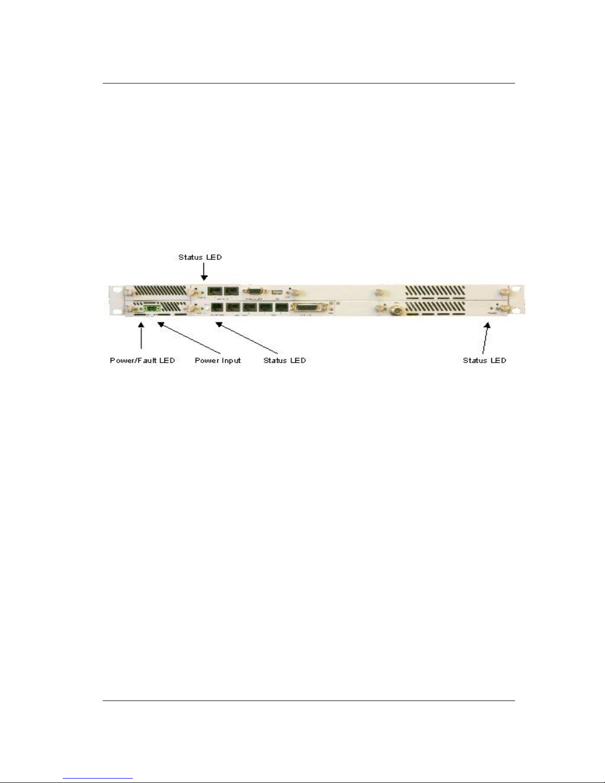
2.4.2 Front Panel Indicators
All models of the ATX-II Digital Radios support a variety of front panel configurations that are
dependent on the network interface and capacity configurations.
Figure 2-2 provides an example of the PDH 8/12/16 E1/T1 1+0 configuration and the associated
LEDs displayed on the
SDIDU
TM
front panel.
Figure 2-2. ATX-II LEDs: SDIDUTM Front Panel Configuration for CW-PB, 1+0 Configuration
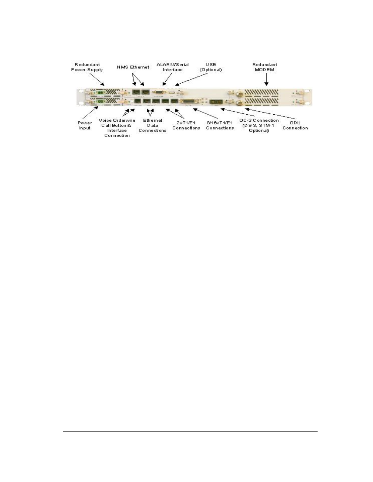
2.4.3 Front Panel Connections
Please refer to the Figure 2-3 for an example of a ATX-II SDIDU
TM
front panel followed by a
descriptive text of the connections.
2-8 GigaCom Wireless - USA Version REV D
MK-MAN-01 USA VERSION ATX-II Digital Radio
Figure 2-3. ATX-II-SB, 1+1 Protection: SDIDUTM Front Panel Connections
The recommended maximum length for all cables to terminal equipment is a maximum of 3
meters. The exception to this recommendation is the length of the ODU/SDIDU
TM
Interconnect
cable, which connects the Outdoor Unit to the Indoor Unit.

User Reference and Installation Manual 2-9
ATX-II Digital Radio MK-MAN-01 USA VERSION
Power Supply Input
DC Input
-48 VDC
-48v (Isolated Input); 2-pin captive power connector. The ATXII Digital Radio requires an input of -48 volts dc ±10% at the
front panel DC Input connector. The total required power is
dependent on the option cards and protection configuration
(1+0, 1+1). The SDIDU
TM
front panel power connector pin
numbering is 1 through 2, from left to right, when facing the
unit front panel. Pin 1 is the power supply return and is
connected to unit chassis ground internally. Pin 2 should be
supplied with a nominal -48 V dc, with respect to the unit
chassis (ground). A ground-isolated supply may be used,
provided it will tolerate grounding of its most positive output.
The recommended power input is -44 to -52 V dc at 2 Amps
minimum. It is recommended that any power supply used be
able to supply a minimum of 100 W to the SDIDU
TM
.
A mating power cable connector is supplied with the ATX-II
SDIDU
TM
. It is a 2-pin plug, 5 mm pitch, manufactured by
Phoenix Contact, P/N 17 86 83 1 (connector type MSTB 2,5/2STF). This connector has screw clamp terminals that
accommodate 24 AWG to 12 AWG wire. The power cable
wire should be selected to provide the appropriate current with
minimal voltage drop, based on the power supply voltage and
length of cable required. The recommended wire size for
power cables under 10 feet in length supplying -48 Vdc is 18
AWG.
The SDIDU
TM
supplies the ODU with all required power via the
ODU/SDIDU
TM
Interconnect cable. The ATX-II Digital Radio
SDIDU
TM
does not have a power on/off switch. When DC
power is connected to the SDIDU
TM
, the digital radio powers
up and is operational. There can be up to 320 mW of RF
power present at the antenna port (external antenna version).
The antenna should be directed safely when power is applied.

2-10 GigaCom Wireless - USA Version REV D
MK-MAN-01 USA VERSION ATX-II Digital Radio
Alarm/Serial Interface
Alarms/Serial
DB-15HD female connector for two Form-C relay alarm
outputs (rated load: 1A @ 24 VDC), two TTL alarm outputs,
four TTL alarm inputs, and Serial Console. The two Form-C
relay alarm outputs can be configured to emulate TTL alarm
outputs.
USB Interface
USB
USB connector, optional.
Voice Orderwire Connector
Voice
Orderwire
Call
Call button to alert operator at link-partner SDIDU of incoming
Voice-Orderwire call.
Voice
Orderwire
RJ-11 modular port connector for voice orderwire interface.
NMS 10/100 Network Management System Connections
10/100 LOC
10/100Base-TX RJ-45 modular local port connector for access
to the ATX-II Network Management System (SNMP).
10/100 CPT
10/100BaseTX RJ-45 modular remote port connector for
access to the ATX-II port Network Management System
(SNMP). This port to be used for consecutive point networks.
ATX-II-100/Ethernet Models: Ethernet 100BaseT Connections
100Base-TX
LOC
100Base-TX RJ-45 modular port connector for the local Fast
Ethernet interface.
100Base-TX
CPT
100Base-TX RJ-45 modular port connector. This port to be
used for consecutive point networks.
T1 Channels
T1 1-2
Two T1/E1 (RJ-48C) interface connections.
T1 3-8/16
Single Molex 60-pin connector containing 14 T1/E1
connections, or DB-26HD 26-pin connector containing 6 T1/E1
connections.

User Reference and Installation Manual 2-11
ATX-II Digital Radio MK-MAN-01 USA VERSION
OC-3 Connection
OC-3 Out
OC-3 type SC connectors for the OC-3 interface.
OC-3 In
OC-3 type SC connectors for the OC-3 interface.
STM-1 Connection
STM-1Out
BNC connector for the STM-1 interface.
STM-1 In
BNC connector for the STM-1 interface.
DS-3/E-3/STS-1 Connection
DS-3 Out
BNC connector for the DS-3/E-3/STS-1 interface.
DS-3 In
BNC connector for the DS-3/E-3/STS-1 interface.
ODU/SDIDUTM Interconnect
To ODU
TNC female connector. Used to connect the ODU to the
SDIDU
TM
. Provides –48VDC and 350 MHz Transmit IF to the
ODU and receives 140 MHz Receive IF from the ODU.
Ground Connection
Ground
On optional ground stud may be installed on the front panel.
2-12 GigaCom Wireless - USA Version REV D
MK-MAN-01 USA VERSION ATX-II Digital Radio
2.5 System Description
The overall digital radio architecture consists of a single 1RU rack mount Software Defined Indoor
Unit
TM
(SDIDUTM) with a cable connecting to an Outdoor Unit (ODU) with an external antenna.
SWITCH
CPU
SNMP
2x 100BASE-TX
User
2x 100BASE-TX
16x T1/E1
Voice
2x100 Mbps
2x100 Mbps*
16x 1.544/
2.048 Mbps
64 Kbps
DS-3/E3/STS-1
155.52 Mbps
4x DS3/E3/
STS1
4x 44.736/34.368/
51.84 Mbps
Future
FRAMER
MODEM/FEC ASIC
Modulation:
BPSK - 256-QAM
Adaptive Equalization:
17 Taps
FEC:
TCM + Reed Solomon
Serial
Digital
IF
Optional I/O Cards
(Small Slot):
Standard I/O
East/Primary Modem
STM-1/OC-3
44.736/34.368/
51.84 Mbps
Primary Power Supply
Secondary Power Supply
Multiplexed
Signal to ODU
-48 Vdc
-48 Vdc
Modem
Control/
Telemetery
IDU Controller
Quad
Mux
MODEM/FEC ASIC
Modulation:
BPSK - 256-QAM
Adaptive Equalization:
17 Taps
FEC:
TCM + Reed Solomon
Digital
IF
West/Secondary Modem
Multiplexed
Signal to ODU
Quad
Mux
Optional I/O Cards
(Large Slot):
2 x 155.52 Mbps
2x STM-1/OC-3
SWITCH
ROH Serial
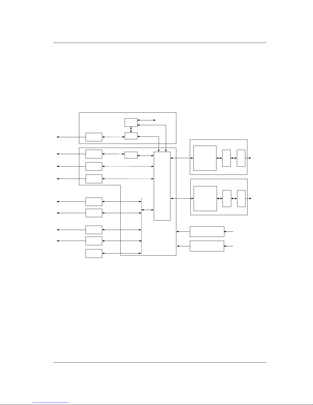
Figure 2-4. SDIDU Block Diagram
Figure 2-4 shows the SDIDU
TM
and interfaces from a functional point of view. The functional
partitions for the I/O, Modem/IF, and power supply modules are shown. The SDIDU
TM
comes with the
standard I/O capability which can be upgraded. In addition, the Modem/IF function is modular. This
allows the addition of a second Modem to suppor t protection or ring architectu res. The power supply
is similarly modular.
The major functions of the SDIDU
TM
can be summarized as follows:
• I/O Processing – The SDIDU
TM
comes with a standard I/O capability that includes support for up to
16xT1/E1 and 2x100Base-TX user payloads, 2x100Base-TX for SNMP, and voice orde rwire. In
addition, option cards for DS-3/E3/STS-1, 1-2 x STM-1/OC-3, and 4xDS-3/E3/STS-1 may be
added. The SDIDU
TM
architecture is flexible and allows for the addition of other I/O types in the
future.

User Reference and Installation Manual 2-13
ATX-II Digital Radio MK-MAN-01 USA VERSION
•
Switch/Framing – The SDIDU
TM
includes an Ethernet Switch and a proprietary Framer that are
designed to support 1+1 protection switching, ring architecture routing, and overall network control
functions.
•
Network Processor – The SDIDU
TM
includes a Network Processor which performs SNMP and
Network Management functions.
•
Modem/IF – The SDIDU
TM
Modem performs forward-error-correction (FEC)e ncoding, PSK/QAM
modulation and demodulation, equalization, a nd FEC de co din g fu nction s. The IF chain provides a
350 MHz carrier and receives 140 or 60 MHz carriers. The multiplexer function is built into an
appliqué that resides in the Modem/IF Module . Two modems can be used for 1+1 protection or
ring architectures.
• Power Supply – The SDIDU
TM
power supply accepts -48 Vdc and supplies the SDIDUTM and ODU
with power. A second redundant power supply may be added as an optional module.
• For the OC-3 configuration, a user rate clock is recovered from clock recovery NCO and provided
to the OC-3/STM-1 I/O card.
The Modem Processor and its associated RAM, ROM, and peripherals control the digital and analog
Modem operation. It also provides configuration and control for both the IF and I/O cards.
The
SDIDU
TM
interfaces with the ODU to receive and provide modulated transmit and receive
waveforms.
The 256-QAM Modem performs the modulation and demod ulation of the payload/wayside/SNMP
data and forward error correction using advanced modulation and coding techniques. Using alldigital processing, the 256-QAM Modem uses robust modulation and forward error correction
coding to minimize the number of bit errors and optimize the radio and network performance.
The 256-QAM Modem also scrambles, descrambles and interleaves/deinterleaves the data
stream in accordance with Intelsat standards to ensure modulation efficiency and resilience to
sustained burst errors. The modulation will vary by application, data rate, and frequency
spectrum. The highest order modulation mode supported is 256 Quadrature Amplitude
Modulation (QAM). Table 2-3 summarizes the TCM/convolutional code rates for each modulation
type supported by the Digital Radio.

2-14 GigaCom Wireless - USA Version REV D
MK-MAN-01 USA VERSION ATX-II Digital Radio
Table 2-3. ATX-II Digital Radio TCM/Convolutional Code Rates
Modulation CC/TCM Code Rate Reed Solomon Code
Rate
BPSK ½ (1)
¾ (1)
QPSK ½ (1)
¾ (1)
16 QAM TCM ¾ (1)
7/8 (1)
32 QAM TCM 4/5 (1)
9/10 (1)
64 QAM TCM 5/6 (1)
11/12 (1)
128QAM TCM
6/7
13/14
(1)
(1)
256 QAM TCM 7/8
15/16
(1)
(1)
Notes:
(1) Codeword byte length, N: 200-255; Message byte length, K: 184-253; check byte length, N-K:
2-20
The RS encoding shall be programmable over the following ranges
• Codeword Byte Length 200 to 255 in steps of 1
•
Message Byte Length 184 to 253 in steps of 1
• Check Bytes 2 to 20 in steps of 2
• Correctable Bytes =Check Bytes/2
The SDIDU
TM
also provides the physical interface for the user payload and network management.
In transmit mode, the Framer merges user payload (OC-3 or Fast Ethernet) with radio overheadencapsulated network management data. This combined data stream is transmitted without any
loss of user bandwidth. In the receive mode, the Framer separates the combined data stream

User Reference and Installation Manual 2-15
ATX-II Digital Radio MK-MAN-01 USA VERSION
received from the 256-QAM Modem. The SDIDUTM supports Scalable Ethernet data rates, such
as 25 or 50 Mbps via the 100BaseT data interface port. The SDIDU
TM
provides network
management data on 10 Mbps ports accessible via the 10/100BaseTX port. The Central
Processor Unit (CPU) provides the embedded control and network element functionality of the
OAM&P. The CPU also communicates with other functions within the SDIDU
TM
for configuration,
control, and status monitoring. The CPU passes appropriate status information to the SDIDU
TM
front panel dis pl ay.
The power supply converts 48 Vdc to the DC voltage levels required by each component in the
system.
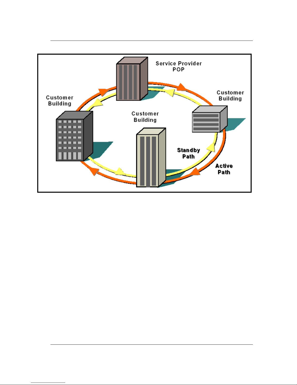
2.6 Consecutive Point Architecture
The consecutive point network architecture is based upon the proven SONET/SDH ring.
Telecommunications service providers traditionally use the SONET/SDH ring architecture to
implement their access networks. A typical SONET/SDH network consists of the service
provider’s Point of Presence (POP) site and several customer sites with fiber optic cables
connecting these sites in a ring configuration (see Figure 2- 5). This architecture lets providers
deliver high bandwidth with high availability to their customers.
2-16 GigaCom Wireless - USA Version REV D
MK-MAN-01 USA VERSION ATX-II Digital Radio
Figure 2-5. Ring Configuration.
SONET/SDH rings are inherently self-healing. Each ring has both an active path and a standby
path. Network traffic normally uses the active path. Should one section of the ring fail, the network
will switch to the standby path. Switchover occurs in seconds. There may be a brief delay in
service, but no loss of payload, thus maintaining high levels of network availability.
The consecutive point architecture implemented in the ATX-II Digital Radio family is based on a
point-to-point-to-point topology that mimics fiber rings, with broadband wireless links replacing inground fiber cable. A typical consecutive point network consists of a POP and several customer
sites connected using ATX-II units. These units are typically in a building in an east/west
configuration. Using east/west configurations, each unit installed at a customer site is logically
connected to two other units via an over-the-air radio frequ ency (RF) link to a unit at an adjacent
site.
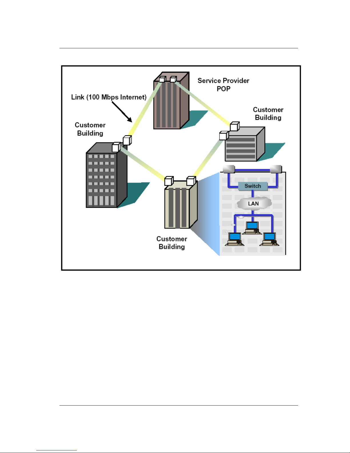
Each consecutive point network typically starts and ends at a POP. A pattern of wireless links and
in-building connections is repeated at each site until all buildings in the network are connected in
a ring as shown in Fi gu r e 2- 6.
User Reference and Installation Manual 2-17
ATX-II Digital Radio MK-MAN-01 USA VERSION
Figure 2-6. Consecutive Point Network
 Loading...