


GN-WLM01
IEEE 802.11b PCMCIA Wireless Adapter
User’s Manual
1

Contents
Chapter1. Product Overview
1-1. Introduction to The Client Adapter ……………………3
1-2. Features ……………………3
1-3. Physical Dimension/Packaging ……………………3
1-4. LED Display Indicator ……………………4
1-5. System Requirements ……………………4
Chapter2. Installing the Client Adapter
2-1. Installing The Windows 2000 Driver & Utility ……………………5
Chapter3. Using The Utility
3-2. Status ……………………8
3-3. Configuration …………………….9
3-4. Encryption …………………….10
3-5. About …………………….12
3-1. Info ……………………6
Chapter4. Specifications
4-1 . System Specifications ……………………..13
4-2. RF Specifications …………………….13
4-3. Regulatory and Environmental Compliance ……………………..13
4-4. Software Specifications …………………….13
4-5. Mechanical Specifications …………………….13
2

Chapter1. Product Overview
1-1. Introduction to The Client Adapter:
This module is made up of the IEEE 8 02.11b M AC, Baseban d, and ra dio com ponents,
PCMCIA interface, two internal antenna.
It uses direct sequence spr ead spectr um (DSS S) technol ogy and implements D BPSK,
DQPSK, and CCK modulation. This provides a very robust radio channel and excellent
receiver sensitivity.
With its PCMCIA Type-II extended form factor, low power consumption, power
management and high-speed wireless data communication, it is ideally suited for
integration into mobil e and ha ndh el d pl at for m.
Furthermore, it provides a set of received signal strength indicator LED. This function
provides a user-friendly intuitional view. From these indicators, users can know the
information of the present received signal strength conveniently and also the use may
take a advantage to adjust the receiving position or direction for getting a better
receiving status.
1-2. Features
Conforms to IEEE 802.11 and IEEE 802.11b specification
Delivers data rate up to 11Mbps.
Dynamic data rate scaling at 11, 5.5, 2, and 1Mbps
Automatic power management to reduce battery use.
Internal antenna diversity.
Supports wireless data encryption with 64-bit /128-bit WEP standard for security.
Driver support Windows 98/98SE/Me, Windows2000/XP.
Received Signal strength indicator LED for a user-friendly intuitional view.
1-3. Physical Dimensions/Packaging
Dimension: 118.4 mm x 54 mm x 6 mm
This module is developed to conform the PCMCIA standard, for Type II extended PC
card. There are five LED: o ne indicati ng power on and the ot hers indi cating the receiv ed RF
signal strength.
3

1-4. LED Display Indicator
1-4-1. Purpose
The LED display indicator is th e functi o n t hat pr ovides the users to rev iew the received
RF signal strength of NIC. It is convenient for users to adjust the location of NIC and then
gain better receive signal strength refer to LED sight.
1-4-2. Description
The LED display window is based on the index of the received RF signal strength. it
specifies the condition of “POOR”, “FAIR”, “GOOD”, and “EXCELLENT”, respectively.
TABLE 1. shows the relation of LED sight and the condition of receiver.
LED sight
Condition of
receiver
Table 1. The relation of LED Sight and condition of receiver.
Note: The LED indictor status shown depended on the data transmission between AP and
Station
POOR FAIR GOOD EXCELLENT
1-5. System Requirements
1-5-1. Supported Platform
IBM PC/AT compatible computer
1-5-2. Supported Operation System
Windows 98/98SE/Me
Windows 2000/XP
4
Chapter2. Installing The Client Adapter
2-1 Installing The Driver & Utility (Apply to any supported OS)
Step 1: Insert our setup CD into your CDROM
Step 2: Execute the setup.exe on our CD
Step 3: If you haven’t ever install any wireless LAN card’s driver, the following window will
pop up, else the setup program will uninstall your previous driver for a afresh
installation.
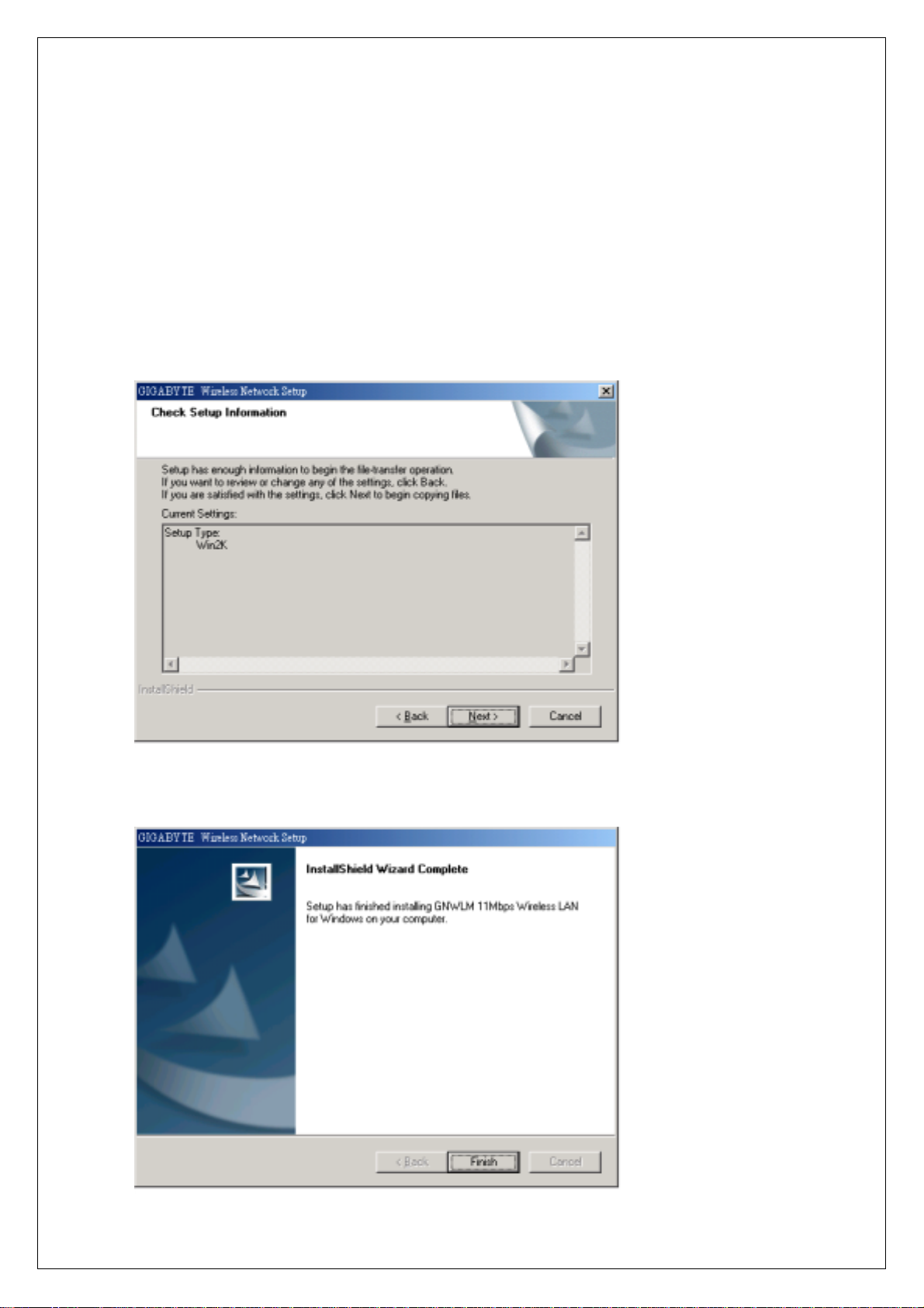
Step 4: Press “Next”.
5

Step 5: Press “Finish”, and then your installation is ok.
Chapter3. Using The Utility
The Wireless LAN Monitor Utility enables you to make configuration chan ges on your
11Mbps Wireless LAN Card. The Wireless LAN Utility consists of window with 5 items for
you to monitor and config ure th e 11Mbps Wi rel ess LAN C ard: Info, Status, Configuration,
Encryptions and About.
3-1. Info:
The Info tab shows you the current Link State of Wireless LAN Card and Reachable
Access points and Stations in the wireless environment.
Link State: There are five kinds of states for a Wireless LAN Card:
Access Point associated: The wireless LAN card is now connecting to an Access Point.
Peer-to-Peer associated: The wireless LAN card is joining a Peer-to-Peer network now.
Access Point scanning: The wireless LAN card now search for an Access Point with the
same network name, or SSID to connect.
Peer-to-Peer scanning: The Wireless LAN Card now searches for another Wireless LAN
6

Card with the same SSID and the same channel to join.
WEP security rejection: This will occur if you join an wireless network with incorrect WEP
key.
The other items in the table are details about the link state and will only be a vailable
when the wireless LAN card is associated with an Access Points or other wireless LAN
card.
SSID: This is also known as network name.
BSSID: This is the MAC address of the Access Point when the Wireless LAN Card
connects an Access Point or a special serial number when the Wireless LAN Card is in
Peer-to-Peer mode.
Channel: This represents the channel now used by the Wireless LAN Card.
TxRate: This represents the transmission rate now the Wireless LAN Card uses.
Signal Quality: This is only available in Access Point mode and represents the quality of
communication between the Wireless LAN Card and Access Point.
Reachable Access Points / Stations:
This item will show you all the other 802.11 Access Points or Wireless LAN Card s in your
wireless environment. The icon in the front of every item represents this point is an Access
Point or a Wireless LAN Card in Peer-to-Peer mode. One can join a network easily by
clicking the SSID which you want to join.
Refresh: Clicking this button, the wireless LAN card will rescan th e wireless environment
an show you all the newest reachable Access Points and Stations.
7

3-2. Status:
The Status tab will show you the detailed status of the wireless net card.
State
This field is used to display the current state of the Wireless LAN Card. When the state is
“Associated “ means normal flow of operation in Infrastructure mode. The PC is connected
to access point. BSSID is shown i n the form of hex digi ts. Networ king is avai lable. A state of
“Scanning ” means that the node is sear ching for avai lable acc ess point and u nabl e detects
the SSID for an available access point within range. This field will also display an error
message if for some reason the driver f ailed to initialize.
Rescan
Pressing the rescan button causes the dr iver to restart and begin i ts Connecti on Procedur e.
The connection procedure differs depending on the Mode of the driver.
Access Point Mode - The driver will scan all available channels continuously until it finds
one or more Access Points that matches its SSID. At that point it will try and authenticate
and associate with the Access Point.
Point-to-Point Mode - The driver will scan for 5 seconds looking for an existing Ad Hoc
networking the same SSID.
Current Channel and Tx Rate
Shows the channel of the radio and transmit rate are being currently used for an active
connection. This value has no meaning when the radio is “Scanning”
Throughput
8

These two fields display the instantaneous wireless Receive and Transmit throughput
displayed in bytes per second. These values are updated every two seconds.
Link Quality
The Link Quality bar graph is only active when the node is in Infrastructure Mode. The bar
graphically displays the quality of the link between the node and its Access Point. A label
summarizes the quality of the link over the bar graph, which can take on one of the
following values:
“Poor”
“Weak”
“Fair”
“Good”
“Excellent”
Signal Strength
The Signal Strength bar graph is only active when the node is in Infrastructure Mode. The
bar graphically displays normalized signal strength as reported by the radio, averaged over
all frames over 100 bytes long that are received from the Access Point.
3-3. Configuration:
The Configuration Tab cont ains sev eral fields where op erating parameter s of the driv er
can be viewed or changed. Changes to any of the parameters in this panel can be applied
to the driver without the need to reboot the PC.
Defaults: Pressing this button restores each field in the panel to its default value. The
Apply Changes button or OK must be pressed before the default values are saved to the
driver and registry.
9

Profile: You can save various wireless settings for different environment. The system
allows you to have 5 different configurations.
Network Name: It is also known as SSID and is the unique name shared among all points
in the wireless network. The SSID must be identical for all points in the network. It is case
sensitive and must not exceed 32 characters.
Network Type:
This field allows you to select from a list of supported Network “Modes”. The modes
displayed have two values: “Peer-to-Peer” and “Access Point”.
Peer-to-Peer: This is the 802.11 peer-to-peer mode of operation. All communication is
done from Client to Client without the use of an Access Point. Peer-to-Peer networking
uses the same SSID for establishing the wireless connection.
Access Point: This mode of operation requires the presence of an 802.11 Access Point.
All communication is done via the Access Point, which relays packets to other wireless
Clients in the BSS as well as to nodes on a wired network such as Ethernet.
Peer-to-Peer channel: This specifies the channel used in wireless communication and
should be set to same channel as the other points in the wireless network. This setting can
only be adjusted in Peer-to-Peer mode.
TX Rate: The transmission rate at which client of AP transmits the data packets. You may
set this to Auto 1 or 2 Mb, 5.5 Mb, 11 Mb, or Fully Automatic.
3-4. Encryption:
To prevent unauthorized wireless stations from accessing data transmitted over the
network, the 11Mbps Wireless LAN Card offers highly secure data encryption, known as
WEP (Wired Equivalent Privacy). If you require high security in transmission, go to the
Encryption tab and do the following.
Pull down the Encryption menu and select either 64bit or 128bit encry pti on me tho d.
Specify the encryption keys. There are two methods to set the WEP keys, as
described below:
10

From the WEP encryption item, pull down the menu and it will list three options:
Disable – Allows wireless adapters communicate with Access Points without any data
encryption.
64 Bit – Requires wireless stations to use data encryption with 64 Bit algorithm when
communicating with the Access Point.
128 Bit – Allows wireless clients to communicate with the Access Point with 128 Bit
encryption algorithm.
The Encryption tab enables you to identify up to 4 di fferent encr ypti on k eys and s elect one
of them to encrypt your transmission data. The key value of your choice may either be:
For 64-bit encryption:
Five alphanumeric characters in the range of “a-z”, “A-Z” and “0-9” (e.g. MyKey)
10 digit hexadecimal values in the range of “A-F” and “0-9” (e.g. 11AA22BB33).
For 128-bit encryption:
13 alphanumeric characters in the range of “a-z”, “A-Z” and “0-9” (e.g. WEPencryption).
26 digit hexadecimal values in the range of “A-F” and “0-9” (e.g.
11AA22BB33123456789ABCDEFF).
Alternatively a Passphase can be entered which is used as a “seed” to randomly
generate the four keys . This sav es considerable time since the same keys must b e e nter e d
into each node on the wireless network.
Key 1 – Key 4
These four fields can be used to manually enter the keys. This may be necessary if you
wish this node to match keys in a different vendor’s product. These fields also display the
11

keys when they are generated using a Pass-phrase.
3-5. About:
About tab shows the product version including the detail of Driver, Configuration Utility, and
NIC firmware version. Users must use this versi on number w hen reporti ng their pr oblems to
technical support.
Chapter4. Specification
12

4-1. System
Standards IEEE 802.11b compliant, Wi-Fi compatible
Host Interface PCMCIA PC Card Type II
Modulation 1Mbps : DBPSK; 2Mbps : DQPSK; 5.5 and 11 Mbps : CCK
Data Rate 1, 2, 5.5, 11 Mbps
Operating Voltage 3.3V / 5V DC
Operating Range Open space : 100 - 300m; Indoor : 30 - 100m
4-2. RF
Frequency Band 2.400 ~ 2.4835 GHz (subject to local regulation)
Radio Technology DSSS (Direct Sequence Spread Spectrum)
Number of Channel
Minimum radiated output power 15dBm @ Nominal Temp Range
Receive Sensitivity Typical: - 83dBm @ 11 Mbps date rate, 8% PER
Antenna Two internal antenna supporting diversity
4-3. Regulatory and Environmental Compliance
EMC certification
Temperature Range Operating : 0 ~ 55 deg C , Storing : -20 ~ 65 deg C
Humidity Max. 95% Non-condensing
4-4. Software
Driver Windows 95/98/Me; Windows 2000/XP; Windows NT4.0
Roaming
Network Protocol
Security 64 bit WEP (128 bit WEP optional)
Management Utility Link Configuration for network join and diagnostic
4-5. Mechanical
Dimensions 118.4 x 54 x 6 mm
11 Channels (US, Canada) 4 channels (France)
14 Channels (Japan) 13 Channels (Most European countries, ETSI)
FCC part 15 (USA)
R&TTE (Europe)
ARIB-Telec (Japan)
Full mobility and seamless roaming
TCP/IP, IPX, NetBEUI, NDIS4, NDIS5, NDIS5.1
Weight 43 g
Packaging Generic, Gigabyte, private labeling optional
LED indicator Power on/Link/Receive d signal strength
13

Federal Communication Commission Interference Statement
This equipment has been tested and found to comply with the limits for a Class B digital
device, pursuant to Part 15 of the FCC Rules. These limits are designed to provide
reasonable protection against harmful interference in a residential installation. This
equipment generat es, uses and can radi ate radio freque ncy energy and, i f n ot installed and
used in accordance with the instructions, may cause harmful interference to radio
communications. However, there is no guarantee that interference will not occur in a
particular installation. If this equipment does cause harmful interference to radio or
television reception, w hich ca n be d eter mined by turni ng t he eq uipment o ff and o n, the user
is encouraged to try to correct the interference by one of the following measures:
- Reorient or relocate the receiving antenna.
- Increase the separation between the equipment and receiver.
- Connect the equipment into an outlet on a circuit different from that to which the receiver
is connected.
- Consult the dealer or an experienced radio/TV technician for help.
FCC Caution: To assure continued compliance, (example - use only shielded interface
cables when connecting to computer or peripheral devices) any changes or modifications
not expressly approved by the party responsible for compliance could void the user's
authority to operate this equipment.
This device complies with Part 15 of the FCC Rules. Operation is subject to the following
two conditions: (1) This device may not cause harmful interference, and (2) this device
must accept any interference received, including interference that may cause undesired
operation.
IMPORTANT NOTE:
FCC Radiation Exposure Statement:
This equipment complies with FCC radiation exposure limits set forth for an uncontrolled
environment. This equipment should be installed and operated with minimum distance
2.5cm between the radiator & your body.
This transmitter must not be co-located or operating in conjunction with any other antenna
or transmitter.
This device and its antenna(s) must not be co-located or operating in conjunction with any
other antenna or transmitter. End-users must be provided with specific operating
instructions for satisfying RF exposure compliance."
14
 Loading...