

Page 1
TA manual ENG.p65
1
1
TA Series User’s Manual
Introduction
Thank you for purchasing TA series. Plea se read the following instructions carefully to ensure
you can use this product safely.
* Please follow the warning signs and instructions of the product.
* Please disconnect the product from the power source before unloading and cleaning
it.
* Do not rub the inside of the product with a wet cloth or expose the product to water in
any case.
* Please turn the power off before connecting or assembling any peripheral.
May/2003
Product features
TA series has been equipped with the motherboards developed by Gigabyte Technology
to ensure the best performance under Windows environment.
Rack-mounted ca se de sign provides easy a ssembly and maintenance, a nd makes system
upgrade a piece of cake!
English
Warning
Improper battery installation may cause explosion.
Use only the same or equivalent batteries for eplacement.
Dispose batteries as instructed by their manufacturers.
Page 2
TA manual ENG.p65
3
TA Series User’s Manual
1.PC case
Overall dimension
With side cover: 70(W)mm x 236(H)mm x 213(D)mm
Without side cover: 64(W)mmx230(H)mmx213(D)mm
Materials of the case has been tested to comply with the UL specification and designed for space and
screw saving purposes. Users simply need to remove one screw from the back to unload the case cover
and access to the inside of the case. Moreover, the case has been designed with anti EMI function and
complies with standard PC safety standards.
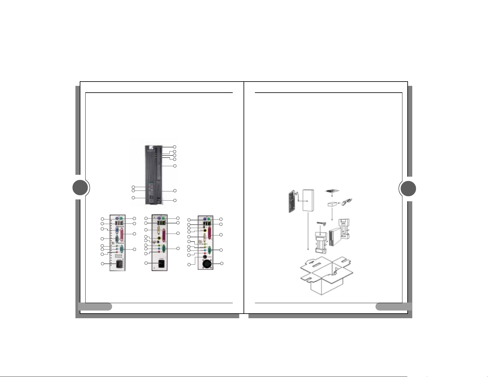
2.Parts on Panels
3
( TA1 )
1
2
3
4
5
6
7
8
Rear Panel
1.Keyboard (PS2)
2.USB port
3.VGA/DVI
4.COM 1
5.Audio Out
English
1
2
3
1
9
2
10
3
11
16
15
5
6
12
7
8
6.Audio In
6.Audio In
7.MIC
7.MIC
8.Power Cord
8.Power Cord
9.Mouse (PS2)
9.Mouse (PS2)
10.LAN (RJ45)
10.LAN (RJ45)
( TA2)
4
5
6
7
8
9
10
9
10
11
4
Front Panel
Front Panel
1.MIC
1.MIC
2.Audio Out
2.Audio Out
3.USB Ports
3.USB Ports
4.Power Button
4.Power Button
5.Power LED
5.Power LED
6.LAN LED
6.LAN LED
7.HDD LED
7.HDD LED
8.CD Button
8.CD Button
9.PCMCIA Slot
9.PCMCIA Slot
10.PCMCIA Button
10.PCMCIA Button
( TA4)
1
2
15
16
3
13
5
6
7
8
11.LPT
11.LPT
12.COM 2
12.COM 2
13.SPDIFOut
13.SPDIFOut
14.System FAN
14.System FAN
15.IEEE 1394
15.IEEE 1394
16.S Video
16.S Video
2
TA Series User’s Manual
Specifications
-Product specification
-PC case
-TA series Motherboard
-Power supply unit
-24X Slim CD-ROM or DVD-Rom (Optional)
-PCMICA Slot (optional)
-2.5-inch Slim HDD (Optional)
-Power cord
-Keyboard and mouse (Optional and subject to real products at shipment)
-Accessories
System Assembly Manual
Driver CD
Ribbon cable
Screws for Slim HDD and Slim CD-ROM
System Packing
Manual and
Driver CD
*
Keyboard
(Optional)
9
10
11
Power cord
*mouse
( Optional)
PC
4
14
0 Specification with “Option” are subject to change without notice.
English
2
Page 3

TA manual ENG.p65
5
TA Series User’s Manual
Step 2: Fix the hard drive with its rack on the four posts and connect the ribbon cable to the
IDE connector (J1).
Installing DOM (DISK On Module)
Step 1: Install DOM on the DOM slot (J1).
5
Attention! Make sure that DOM and HDD cannot be used at the same time.
Installing DOC (Disk On Chip)
Step 1: Install DOC on the DOC slot (U12)
Pin 1
4
TA Series User’s Manual
3. System equipment installation
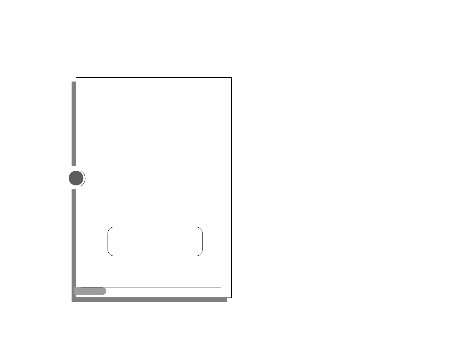
Unload case
Step 1: Remove the screw from the bottom of the case.
Step 2: Grasp the handle on the panel and pull out the case.
Installing hard drive
Step 1: Fix the hard drive on the base with screws and connect the hard drive with the IDE
ribbon cable.
Screw stands (Attention! Install hard drive on top of the screw stands on the base.)
4
Attention! Use 3.3V DOC.
English
Red (fool-proof) wire should be connected to PIN 1.
(Attention! Make sure that the red (fool-proof) wire on the ribbon cable should be connected to PIN 1 of the hard drive as shown
below.)
English
Page 4

TA manual ENG.p65
7
TA Series User’s Manual
Installing PCMCIA
7
Step 1: Fix PCMCIA card next to chassis with screws.
Step 2: Unload the part from another side of the PC. Then fix the PCMCIA card on the bolts
and Fix the PCMCIA Card with screws.
( C3 Type)
6
TA Series User’s Manual
Installing CD-ROM
Step 1: Fix the slim CD-ROM on the base with 4 screws (2 on each side).
Step 2: Slide slim CD-ROM and the base to the rack (J4).
Step 3: Fix the CD-ROM and the base on the rack with 2 screws.
6
Step 3: Re-Fix the parts with screws.
English
( P4 Type)
English
Page 5

TA manual ENG.p65
8
TA Series User’s Manual
Installing memory
Align the fool-proof clicks on the bottom of the RAM module to the socket, and the locks on the socket
should securely lock on the clicks at sides of the module as shown in the above picture.
Clicks at sides of the RAM module
SDRAM
Make sure the direction of the foolproof groove must be the same as that of the
Notes
1. Please use high quality CDR or CDRW to prevent disks from breaking when running at high
speed.
2. Specification of hardware is subject to change without notice.
3. Please visit our site at http://www.gigabyte.com.tw/ to download the latest version of drivers.
Cautions
Improper battery installation may cause explosion. Use only the same or equivalent batteries
for replacement. Dispose batteries as instructed by their manufacturers.
English
memory slot on the motherboard.
DDR
8
 Loading...