

Gigabyte R161-340, LGA3647 Service Manual

R161-340
Dual LGA3647 sockets motherboard for Intel® Scalable Family Processors
Service Guide
Rev. 1.0

Copyright
© 2019 GIGA-BYTE TECHNOLOGY CO., LTD. All rights reserved.
The trademarks mentioned in this manual are legally registered to their respective owners.
Disclaimer
Information in this manual is protected by copyright laws and is the property of GIGABYTE.
Changes to the specications and features in this manual may be made by GIGABYTE without
prior notice. No part of this manual may be reproduced, copied, translated, transmitted, or pub-
lished in any form or by any means without GIGABYTE's prior written permission.
Documentation Classications
In order to assist in the use of this product, GIGABYTE provides the following types of documentations:
For detailed product information, carefully read the User's Manual.
For More Information
For related product specications, the latest rmware and software, and related information, please visit
our website at:
http://www.gigabyte.com
For GIGABYTE distributors and resellers, additional sales & marketing materials are available from our
reseller portal:
http://reseller.b2b.gigabyte.com
For further information & technical assistance, please contact your GIGABYTE sales representative.
You may also message GIGABYTE server directly by email, Facebook or twitter
Email: server.grp@gigabyte.com
Facebook: https://www.facebook.com/gigabyteserver
Conventions
The following conventions are used in this user's guide:
NOTE!
Gives bits and pieces of additional
information related to the current topic.
CAUTION!
Gives precautionary measures to
avoid possible hardware or software problems.
WARNING!
Alerts you to any damage that might
result from doing or not doing specic actions.
Server Warnings and Cautions
Before installing a server, be sure that you understand the following warnings and cautions.
WARNING!
To reduce the risk of electric shock or damage to the equipment:
• Do not disable the power cord grounding plug. The grounding plug is an important safety
feature.
• Plug the power cord into a grounded (earthed) electrical outlet that is easily accessible at all
times.
• Unplug the power cord from the power supply to disconnect power to the equipment.
• Do not route the power cord where it can be walked on or pinched by items placed against it.
Pay particular attention to the plug, electrical outlet, and the point where the cord extends from
the server.
WARNING!
To reduce the risk of personal injury from hot surfaces, allow the drives and the internal
system components to cool before touching them.
WARNING!
This server is equipped with high speed fans. Keep away from hazardous moving fan
blades during servicing.
CAUTION!
• Do not operate the server for long periods with the access panel open or removed. Operat-
ing the server in this manner results in improper airow and improper cooling that can lead to
thermal damage.
• Danger of explosion if battery is incorrectly replaced.
• Replace only with the same or equivalent type recommended by the manufacturer.
• Dispose of used batteries according to the manufacturer’s instructions.

Electrostatic Discharge (ESD)
CAUTION!
ESD CAN DAMAGE DRIVES, BOARDS, AND OTHER PARTS. WE RECOMMEND THAT YOU
PERFORM ALL PROCEDURES AT AN ESD WORKSTATION. IF ONE IS NOT AVAILABLE,
PROVIDE SOME ESD PROTECTION BY WEARING AN ANTI-STATIC WRIST STRAP ATTACHED TO CHASSIS GROUND -- ANY UNPAINTED METAL SURFACE -- ON YOUR SERVER
WHEN HANDLING PARTS.
Always handle boards carefully. They can be extremely sensitive to ESD. Hold boards only by
their edges without any component and pin touching. After removing a board from its protective
wrapper or from the system, place the board component side up on a grounded, static free surface. Use a conductive foam pad if available but not the board wrapper. Do not slide board over
any surface.
System power on/off: To remove power from system, you must remove the system from rack.
Make sure the system is removed from the rack before opening the chassis, adding, or removing
any non hot-plug components.
Hazardous conditions, devices and cables: Hazardous electrical conditions may be present
on power, telephone, and communication cables. Turn off the system and discon-nect the cables
attached to the system before servicing it. Otherwise, personal injury or equipment damage can
result.
Electrostatic discharge (ESD) and ESD protection: ESD can damage drives, boards, and
other parts. We recommend that you perform all procedures in this chapter only at an ESD work-
station. If one is not available, provide some ESD protection by wearing an antistatic wrist strap
attached to chassis ground (any unpainted metal surface on the server) when handling parts.
ESD and handling boards: Always handle boards carefully. They can be extremely sensi-tive to
electrostatic discharge (ESD). Hold boards only by their edges. After removing a board from its
protective wrapper or from the system, place the board component side up on a grounded, static
free surface. Use a conductive foam pad if available but not the board wrapper. Do not slide
board over any surface.
Installing or removing jumpers: A jumper is a small plastic encased conductor that slips over
two jumper pins. Some jumpers have a small tab on top that can be gripped with n-gertips or
with a pair of ne needle nosed pliers. If the jumpers do not have such a tab, take care when us-
ing needle nosed pliers to remove or install a jumper; grip the narrow sides of the jumper with the

pliers, never the wide sides. Gripping the wide sides can dam-age the contacts inside the jumper,
causing intermittent problems with the function con-trolled by that jumper. Take care to grip with,
but not squeeze, the pliers or other tool used to remove a jumper, or the pins on the board may
bend or break.
CAUTION!
Risk of explosion if battery is replaced incorrectly or with an incorrect type. Replace the battery
only with the same or equivalent type recommended by the manufacturer. Dispose of used batteries according to the manufacturer’s instructions.

Table of Contents
Chapter 1 Hardware Installation ...................................................................................10
1-1 Installation Precautions .................................................................................. 10
1-2 Product Specications .................................................................................... 11
1-3 System Block Diagram ................................................................................... 14
Chapter 2 System Appearance ..................................................................................... 15
2-1 Front View ...................................................................................................... 15
2-2 Rear View ....................................................................................................... 15
2-3 Front Panel LED and Buttons ........................................................................ 16
2-4 Rear System LAN LEDs ................................................................................. 17
2-5 Hard Disk Drive LEDs .................................................................................... 18
2-6 Power Supply Unit LED .................................................................................. 19
Chapter 3 System Hardware Installation ......................................................................21
3-1 Removing and Installing the Chassis Cover .................................................. 22
3-2 Removing and Installing the Fan Duct ........................................................... 23
3-3 Removing and Installing the CPU and Heat Sink ........................................... 24
3-4 Removing and Installing Memory ................................................................... 26
3-4-1 Six-Channel Memory Conguration ........................................................................26
3-4-2 Removing and Installing a Memory Module ...........................................................27
3-4-3 DIMM Population Table ..........................................................................................27
3-5 Removing and Installing the PCI Expansion Card ......................................... 28
3-6 Removing and Installing the Hard Disk Drive ................................................. 29
3-7 Installing and Removing an M.2 Solid State Drive ......................................... 30
3-8 Replacing the Fan Assembly ..........................................................................31
3-9 Removing and Installing the Power Supply .................................................... 32
3-10 Cable Routing ................................................................................................33
Chapter 4 Motherboard Components ...........................................................................35
4-1 Motherboard Components ............................................................................. 35
4-2 Jumper Settings ............................................................................................. 37
Chapter 5 BIOS Setup .................................................................................................. 39
5-1 The Main Menu .............................................................................................. 41
5-2 Advanced Menu ............................................................................................. 44
5-2-1 Trusted Computing .................................................................................................45
5-2-2 Serial Port Console Redirection .............................................................................46
- 7 -

5-2-3 SIO Conguration ...................................................................................................49
5-2-4 PCI Subsystem Settings .........................................................................................50
5-2-5 USB Conguration ..................................................................................................52
5-2-6 Post Report Conguration ......................................................................................53
5-2-7 NVMe Conguration ...............................................................................................54
5-2-8 Chipset Conguration .............................................................................................55
5-2-9 Network Stack Conguration ..................................................................................56
5-2-10 iSCSI Conguration ................................................................................................57
5-2-11 Intel(R) I210 Gigabit Network Connection ..............................................................58
5-2-12 VLAN Conguration ................................................................................................60
5-2-13 Driver Health ...........................................................................................................62
5-3 Chipset Setup Menu ....................................................................................... 63
5-3-1 Processor Conguration .........................................................................................64
5-3-2 Common RefCode Conguration ...........................................................................67
5-3-3 UPI Conguration ...................................................................................................68
5-3-4 Memory Conguration ............................................................................................69
5-3-5 IIO Conguration ....................................................................................................71
5-3-6 Advanced Power Management Conguration ........................................................73
5-3-7 PCH Conguration .................................................................................................76
5-3-8 Miscellaneous Conguration ..................................................................................78
5-3-9 Server ME Conguration ........................................................................................79
5-3-10 Runtime Error Logging ...........................................................................................80
5-3-11 Power Policy ...........................................................................................................82
5-4 Server Management Menu ............................................................................. 84
5-4-1 System Event Log ..................................................................................................86
5-4-2 View FRU Information ............................................................................................87
5-4-3 BMC VLAN Conguration .......................................................................................88
5-4-4 BMC Network Conguration ...................................................................................89
5-4-5 IPv6 BMC Network Conguration ...........................................................................90
5-5 Security Menu ................................................................................................ 91
5-5-1 Secure Boot ...........................................................................................................92
5-6 Boot Menu ...................................................................................................... 94
5-6-1 UEFI NETWORK Drive BBS Priorities ..................................................................96
5-6-2 UEFI Application Boot Priorities
................................................................... 97
5-7 Save & Exit Menu ........................................................................................... 98
5-8 BIOS POST Codes ...................................................................................... 100
5-8-1 AMI Standard - PEI ...............................................................................................100
5-8-2 AMI Standard - DXE .............................................................................................100
5-8-3 AMI Standard - ERROR .......................................................................................102
5-8-4 Intel UPI POST Codes ..........................................................................................103
5-8-5 Intel UPI Error Codes ...........................................................................................103
5-8-6 Intel MRC POST Codes .......................................................................................104
- 8 -

5-8-7 Intel MRC Error Codes .........................................................................................104
5-8-8 Intel PM POST Codes ..........................................................................................105
5-8-9 Intel PM POST Codes ..........................................................................................105
5-9 BIOS POST Beep code (AMI standard) ....................................................... 106
5-9-1 PEI Beep Codes ...................................................................................................106
5-9-2 DXE Beep Codes .................................................................................................106
5-10 BIOS Recovery Instruction ........................................................................... 107
- 9 -

Chapter 1 Hardware Installation
1-1 Installation Precautions
The motherboard/system contain numerous delicate electronic circuits and components which
can become damaged as a result of electrostatic discharge (ESD). Prior to installation, carefully
read the service guide and follow these procedures:
• Prior to installation, do not remove or break motherboard S/N (Serial Number) sticker or
warranty sticker provided by your dealer. These stickers are required for warranty validation.
• Always remove the AC power by unplugging the power cord from the power outlet before
installing or removing the motherboard or other hardware components.
• When connecting hardware components to the internal connectors on the motherboard,
make sure they are connected tightly and securely.
• When handling the motherboard, avoid touching any metal leads or connectors.
• It is best to wear an electrostatic discharge (ESD) wrist strap when handling electronic
components such as a motherboard, CPU or memory. If you do not have an ESD wrist
strap, keep your hands dry and rst touch a metal object to eliminate static electricity.
• Prior to installing the motherboard, please have it on top of an antistatic pad or within an
electrostatic shielding container.
• Before unplugging the power supply cable from the motherboard, make sure the power
supply has been turned off.
• Before turning on the power, make sure the power supply voltage has been set according to
the local voltage standard.
• Before using the product, please verify that all cables and power connectors of your
hardware components are connected.
• To prevent damage to the motherboard, do not allow screws to come in contact with the
motherboard circuit or its components.
• Make sure there are no leftover screws or metal components placed on the motherboard or
within the computer casing.
• Do not place the computer system on an uneven surface
• Do not place the computer system in a high-temperature environment.
• Turning on the computer power during the installation process can lead to damage to
system components as well as physical harm to the user.
• If you are uncertain about any installation steps or have a problem related to the use of the
product, please consult a certied computer technician.
.
- 10 - Hardware Installation

1-2 Product Specications
Socket
CPU 2nd Generation Intel® Xeon® Scalable and Intel® Xeon® Scalable Processors
Intel® Xeon® Platinum Processor, Intel® Xeon® Gold Processor, Intel® Xeon®
Silver Processor and Intel® Xeon® Bronze Processor
CPU TDP up to 125W
NOTE: If only 1 CPU is installed, some PCIe or memory functions might be
unavailable
Socket 2 x LGA 3647
Socket
Chipset
Memory 16 x DIMM slots
LAN 2 x 1Gb/s LAN ports (Intel® I210-AT)
Expansion Slot Riser Card CRS1014:
Socket P
Intel® C621 Express Chipset
DDR4 memory supported only
6-channel memory architecture
RDIMM modules up to 64GB supported
LRDIMM modules up to 128GB suppor ted
1.2V modules: 2933( 1DPC)/2666/2400/2133 MHz
NOTE: 2933MHz for 2nd Generation Intel® Xeon® Scalable Processors only
1 x 10/100/1000 management LAN
* 2 x 10Gb/s LAN ports (Intel® X557) as an option
* 2 x 25Gb/s SFP28 ports (Mellanox® ConnectX-4 Lx) as an option
- 1 x PCIe x16 slots (Gen3 x16), Full height half-length
Riser Card CRS1015:
- 1 x PCIe x16 slot (Gen3 x16), Full height half-length
2 x M.2 slots:
- M-key
- PCIe Gen3 x4
- Supports NGFF-2260/2280 cards
Video Integrated in Aspeed® AST2500
2D Video Graphic Adapter with PCIe bus interface
1920x1200@60Hz 32bpp, DDR4 SDR AM
Storage 4 x 3.5" SATA/SAS hot-swappable HDD/SSD bays
2.5" HDD/SSD supported
SAS card is required for SAS devices support
1 x 2.5" internal xed SATA HDD/SSD bay
2 x 2.5" internal xed SATA HDD/SSD bays as an option
SATA 2 x 7-pin SATA III 6Gb/s with SATA DOM supported
By using pin_8 or external cable for power function
Hardware Installation - 11 -
SAS Supported via add-on SAS Card
Support RAID
Function
Internal
Connectors
Front Panel
LED/Buttons
Rear Panel I/O 2 x USB 3.0
Backplane I/O 4 x SATA/SAS ports
TPM 1 x TPM header with SPI interface
Intel® SATA RAID 0/1/10/5
2 x Power supply connectors
5 x SlimSAS connectors
2 x SATA 7-pin connectors
2 x CPU fan headers
1 x USB 3.0 header
1 x TPM header
1 x VROC connector
1 x Front panel header
1 x HDD back plane board header
1 x IPMB connector
1 x Clear CMOS jumper
1 x BIOS recovery jumper
2 x USB 3.0
1 x Power button with LED
1 x ID button with LED
1 x Reset button
1 x NMI button
1 x System status LED
1 x HDD activity LED
2 x LAN activity LEDs
1 x VGA
1 x COM (as an option)
2 x RJ45
1 x MLAN
1 x ID button with LED
Bandwidth: SATAIII 6Gb/s or SAS 12Gb/s per port
Optional TPM2.0 kit: CTM010
- 12 - Hardware Installation
System
Management
Aspeed® AST2500 management controller
Avocent® MergePoint IPMI 2.0 web interface:
Network settings
Network security settings
Hardware information
Users control
Services settings
IPMI settings
Sessions control
LDAP settings
Power control
Fan proles
Voltages, fans and temperatures monitoring
System event log
Events management (platform events, trap settings, email settings)
Serial Over LAN
vKVM & vMedia (HTML5)
Power Supply 1 x 550W single PSUs
80 PLUS Platinum
AC Input:
- 100-240V~/ 8- 4A, 50 -60Hz
DC Input:
- 240Vdc/ 2.75A
DC Output:
- 550W
+12V/ 44A
+12Vsb/ 2.1A
* Enable to upgrade to 2 x 550W redundant PSU (as an option)
Environment
Ambient
Operating temperature: 10°C to 35°C
Non-operating temperature: -40°C to 60°C
Temperature
Operating humidity: 8-80% (non-condensing)
Relative
Non-operating humidity: 20%-95% (non-condensing)
Humidity
System
Dimension
* We reserves the right to make any changes to the product specications and product-related information without
prior notice.
1U
438mm (W) x 43.5mm (H) x 730mm (D)
Hardware Installation - 13 -
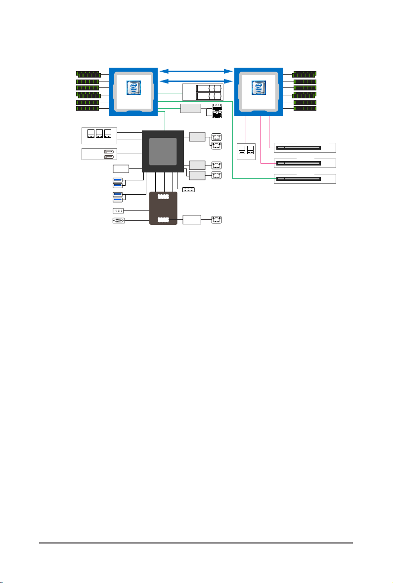
1-3 System Block Diagram
6 Channels
DDR4
2933 MHz (1DPC)
2666 MHz (2DCP)
8 x DIMM slots
3 x SlimLine SAS
2 x SSATAIII
(SSATA DOM)
Front 2x USB 3.0
Rear 2 x USB 3.0
COM (Header)
PCIe3.0
PCIe3.0
PCIe3.0 x8
PCH
PCIe3.0 x1
BMC
MAC
x4
x16
Uplink x8
LPC
UPI 10.4GT/s
UPI 10.4GT/s
2 x M.2
Mellanox
SFP+/SFP28
SPI TPM
10/100/1G
PHY(1ch)
Intel
X557-AT2
Intel
I210
Intel
I210
TPM
2 x 10G SFP+
2 x 25G SFP28
(Option)
2 x 10G LAN
(option)
2 x 1G LAN
MLAN
2 x U.2
CPU1
Skylake-SP
LGA 3647
Socket P0
x4
PCIe3.0
6 Channels
DDR4
2A~2D
2933 MHz (1DPC)
2666 MHz (2DCP)
16
x
PCIe3.0
8 x DIMM slots
16
x
PCIe3.0
CNVP140 (option)
PCIe x16
CRS1015
CRS1014
PCIe x16
PCIe x16
CPU0
Skylake-SP
LGA 3647
Socket P0
8 x SATAIII
4 x SSATAIII
2 x SSATAIII
SW_RAID
For VROC
VGA
DMI3 x 4
Intel C621
Lewisburg
2 x USB 2.0
ASPEED
AST2500
- 14 - Hardware Installation

1 2
Chapter 2 System Appearance
7
6
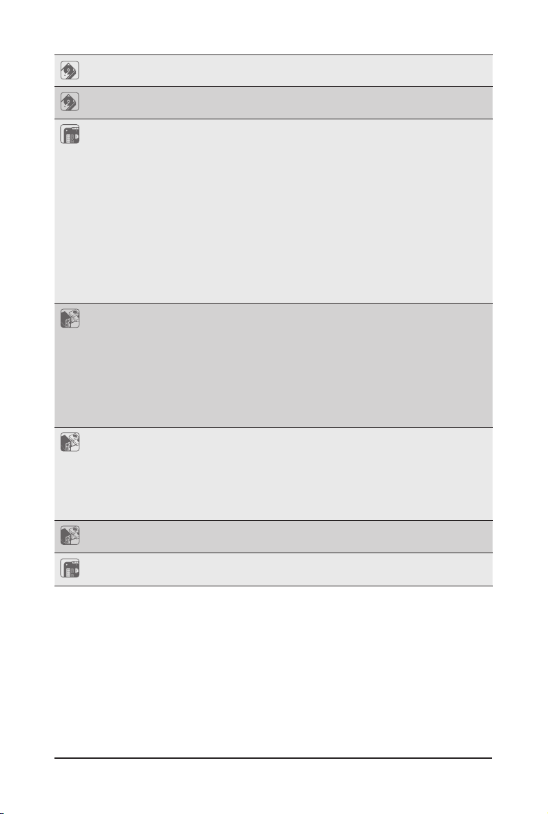
2-1 Front View
HDD1 HDD2 HDD3 HDD4
No. Description
1.
2. Front USB 3.0 ports
Front Panel LEDs and buttons
• Refer to Chapter
of the LEDs.
2-2 Rear View
• Refer to Chapter
the LEDs.
2-3 Front Panel LED
1 2 3 4
No. Description
1. VGA Port
2. 1Gbe LAN Port x 2
3. USB 3.0 Port x 2
4. 10/100/1000 Server management LAN port
5. ID Button
6. PCIe Card Bay #1
7. PCIe Card Bay #2
2-4 Rear System LAN LEDs
and Buttons for a detailed description of the function
5
for a detailed description of the function of
- 15 - System Appearance
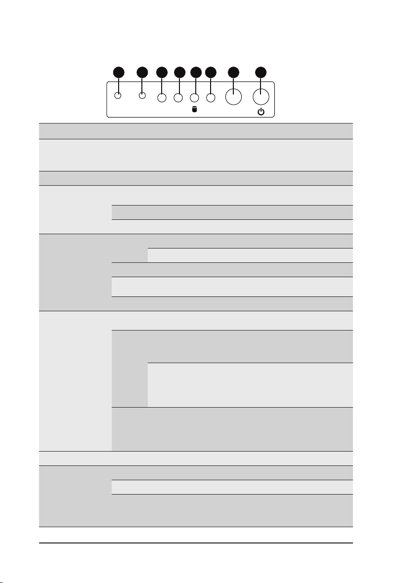
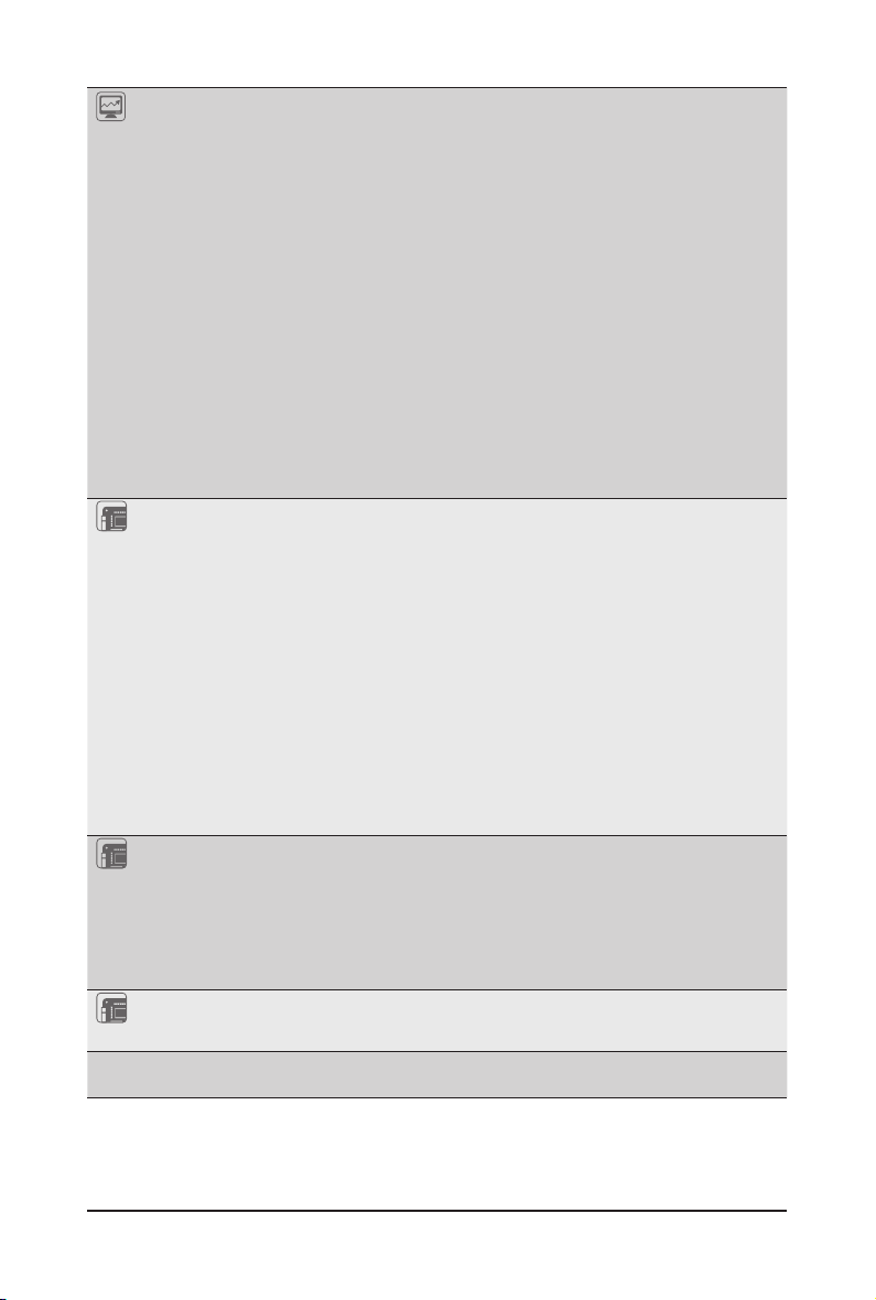
2-3 Front Panel LED and Buttons
87654321
NMI
RST
L1
L2 SYS
No. Name Color Status Description
Press the button server generates a NMI to the processor
1.
NMI button
2.
Reset Button Press the button to reset the system.
LAN 1/2
3/4.
Active/Link
LEDs
HDD Status
5.
LED
System
6.
Status LED
7.
ID Button Press the button to activate system identication
Power button
8.
with LED
Green
Green Blink Data trasmission or receiving is occuring
N/A Off No data transmission or receiving is occuring
Green
Amber On HDD fault
Green/
Amber
N/A Off No HDD access or no HDD fault.
Green
Amber
N/A Off
Green On System is powered on
Green Blink System is in ACPI S1 state (sleep mode)
N/A Off
if the multiple-bit ECC errors occur, which effectively halt
the server.
Solid
Link between system and network or no access.
On
On HDD locate
Blink HDD access
Blink HDD rebuilding
Solid
System is operating normally.
On
Critical condition, may indicate:
Solid
System fan failure
On
System temperature
Non-critical condition, may indicate:
Redundant power module failure
Blink
Temperature and voltage issue
Chassis intrusion
System is not ready, may indicate:
POST error
NMI error
Processor or terminator missing
• System is not powered on or in ACPI S5 state
• System is in ACPI S4 state (hibernate mode)
ID
(power off)
System Appearance - 16 -
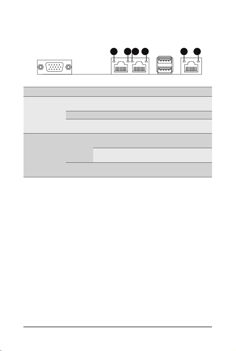
2-4 Rear System LAN LEDs
1 2 1 221
No. Name Color Status Description
Yel low On 1 Gbps data rate
1GbE
1.
2.
Speed LED
1GbE
Link/
Activity
LED
Green On 100 Mbps data rate
N/A Off 10 Mbps data rate
On Link between system and
Green
Blink Data transmission or receiving is occurring
N/A Off No data transmission or
network or no access
receiving is occurring
System Appearance - 17 -
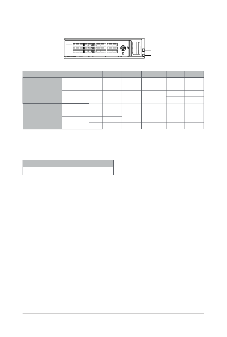
2-5 Hard Disk Drive LEDs
No RAID configuration
(via HBA, PCH)
RAID configuration
(via HW RAID Card or
SW RAID Card)
RAID SKU
Removed HDD Slot
(LED on Back Panel)
Removed HDD Slot
Disk LED
(LED on
Back Panel)
Disk LED
LED1
Locate
ON(*1)
Green
Amber
ON(*1) OFF --
Green
Amber
Green
Amber
ON(*1)
Green
Amber
NOTE:
*1: Depends on HBA/Utility Spec.
*2: Blink cycle depends on HDD's activity signal.
*3: If HDD is pulled out during rebuilding, the disk status of this HDD is regarded as faulty.
LED 2
Green
HDD Present No HDD
ON
OFF
OFF
OFF
ON
OFF
OFF
HDD Fault
OFF
OFF
OFF
OFF
OFF
ON
ON
/('
/('
Rebuilding
(Low Speed: 2 Hz)
(*3)
(*3)
HDD
Access
BLINK (*2)
OFF
--
--
BLINK (*2)
OFF
--
--
HDD Present
(No Access)
OFF
OFF
--
OFF
OFF
--
--
- 18 - System Appearance
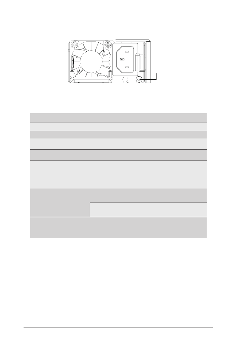
2-6 Power Supply Unit LED
State Description
Off No AC power to all power supplies
GREEN Output ON and OK
1Hz Blink GREEN AC present/ only standby on/ Cold redundant mode
2Hz Blink GREEN Power supply F.W updateing mode
Green BLINKING
0.25 Sec./On
0.25 Sec./Off
2Hz
Amber
1Hz Blink AMBER
PSU Sleep Mode (cold Redundant/Ofine mode)
AC cord unplugged or AC power lost; with a second
PSU LED
power supply in parallel still with AC input power
Power supply critical event causing shut down:
failure, OCP, OVP, Fan Fail, UVP
Power supply warning events where the
power supply continues to operate:
high temp, high power, high current, slow fan
System Appearance - 19 -

This page intentionally left blank
System Appearance - 20 -

Chapter 3 System Hardware Installation
Pre-installation Instructions
Computer components and electronic circuit boards can be damaged by discharges of static
electricity. Working on computers that are still connected to a power supply can be extremely
dangerous. Follow the simple guidelines below to avoid damage to your computer or injury to
yourself.
• Always disconnect the computer from the power outlet whenever you are working inside the
computer case.
• If possible, wear a grounded wrist strap when you are working inside the computer case.
Alternatively, discharge any static electricity by touching the bare metal system of the computer
case, or the bare metal body of any other grounded appliance.
• Hold electronic circuit boards by the edges only. Do not touch the components on the board
unless it is necessary to do so. Do not ex or stress the circuit board.
• Leave all components inside the static-proof packaging until you are ready to use the component
for the installation.
- 21 - System Hardware Installation
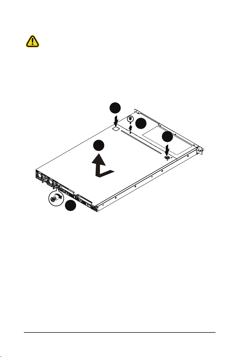
3-1 Removing and Installing the Chassis Cover
3
Before you remove or install the system cover
• Make sure the system is not turned on or connected to AC power.
Follow these instructions to remove the chassis covers:
1. Loosen and remove the two thumbscrews securing the back cover.
2. Push down the indentation located at the side of the back chassis
3. Slide the cover horizontally to the back and remove the cover in the direction of the arrow.
4. To reinstall the chassis cover follow steps 1-3 in reverse order.
1
3
4
2
System Hardware Installation - 22 -
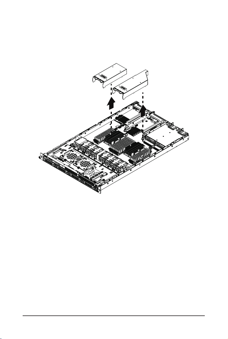
3-2 Removing and Installing the Fan Duct
Follow these instructions to remove the fan duct:
1. Lift up to remove the two fan ducts
2. To install the fan duct, align the fan duct with the guiding groove. Push down the fan duct into
chassis until its rmly seats
- 23 - System Hardware Installation
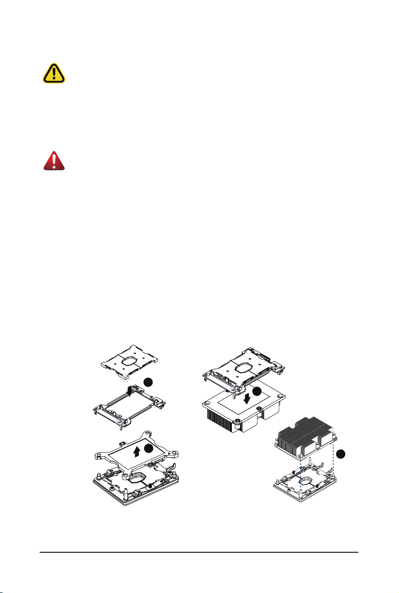
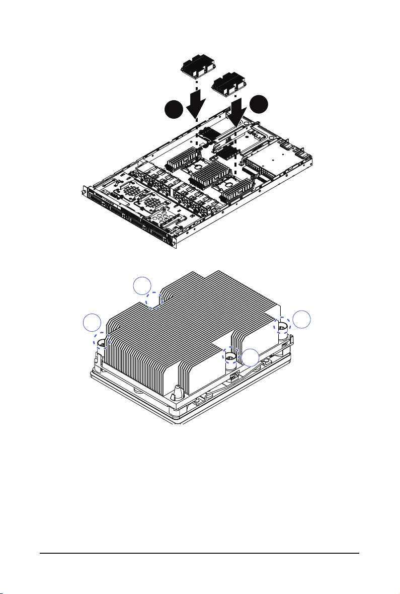
3-3 Removing and Installing the CPU and Heat Sink
Read the following guidelines before you begin to install the CPU:
• Make sure that the motherboard supports the CPU.
• Always turn off the computer and unplug the power cord from the power outlet before installing
the CPU to prevent hardware damage.
• Unplug all cables from the power outlets.
• Disconnect all telecommunication cables from their ports.
• Place the system unit on a at and stable surface.
• Open the system according to the instructions.
WARNING!
Failure to properly turn off the server before you start installing components may cause serious
damage. Do not attempt the procedures described in the following sections unless you are a
qualied service technician.
Follow these instructions to install the CPU:
1. Align and install the processor on the carrier.
NOTE:
the underside of the heat sink.
2. Carefully ip the heatsink over. Then install the carrier assembly on the bottom of the heatsink and
make sure the gold arrow is located in the correct direction.
3. Remove the CPU cover.
NOTE:
4. Align the heatsink with the CPU socket by the guide pins and make sure the gold arrow is located in
the correct direction. Then place the heatsink onto the top of the CPU socket.
5. To secure the heatsink, tighten the screws in a sequential order (1g2g3g4).
NOTE:
Apply thermal compound evenly on the top of the CPU. Remove the protective cover from
Save and replace the CPU cover if the processor is removed from its socket.
When dissambling the heatsink, loosen the screws in reverse order (4g3g2g1).
1
3
System Hardware Installation - 24 -
2
4
3
5
6
2
1
4
- 25 - System Hardware Installation
3-4 Removing and Installing Memory
Read the following guidelines before you begin to install the memory:
• Make sure that the motherboard supports the memory. It is recommended that memory of the
same capacity, brand, speed, and chips be used.
• Always turn off the computer and unplug the power cord from the power outlet before installing
the memory to prevent hardware damage.
• Memory modules have a foolproof design. A memory module can be installed in only one
direction. If you are unable to insert the memory, switch the direction.
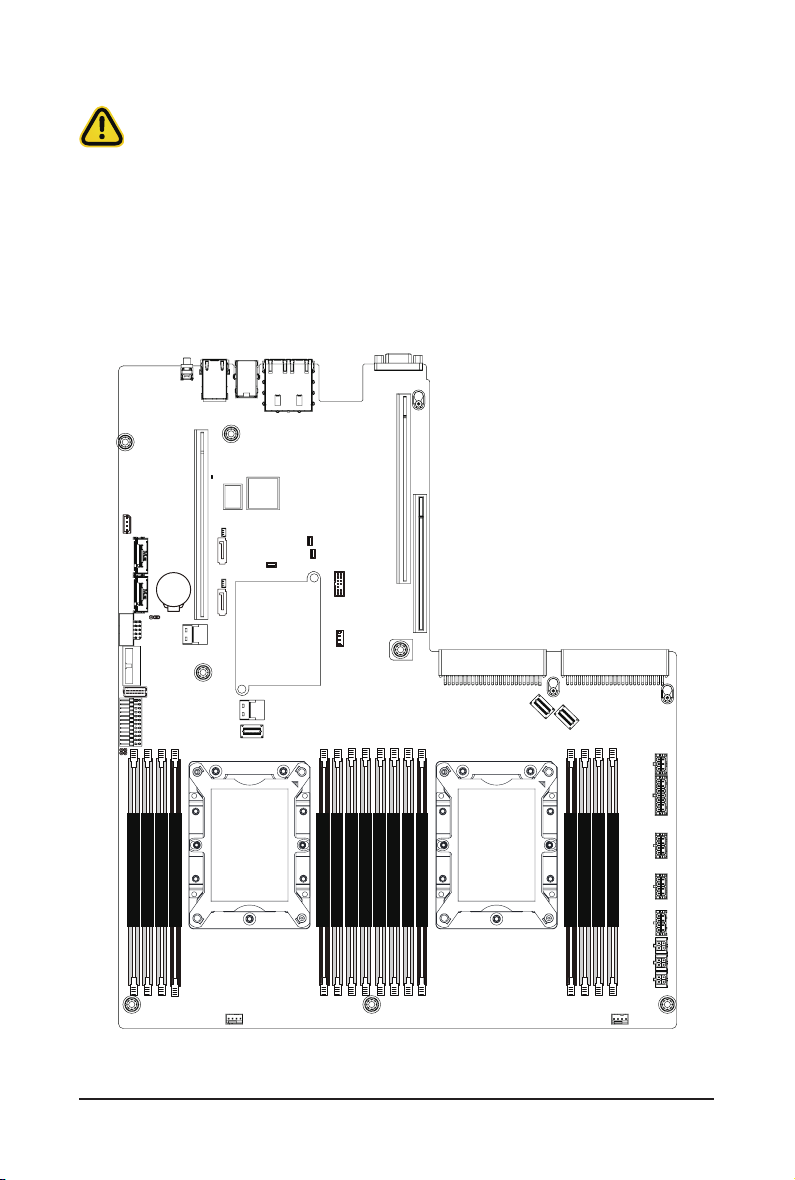
3- 4-1 Six-Channel Memory Conguration
This motherboard provides 16 DDR4 memory sockets and supports Six Channel Technology. After the
memory is installed, the BIOS will automatically detect the specications and capacity of the memory.
CPU0 CPU1
DIMM_P0_F0
DIMM_P0_E0
DIMM_P0_D0
DIMM_P0_D1
System Hardware Installation - 26 -
DIMM_P0_C0
DIMM_P0_B0
DIMM_P0_A1
DIMM_P0_A0
DIMM_P1_L0
DIMM_P1_K0
DIMM_P1_J0
DIMM_P1_J1
DIMM_P1_G1
DIMM_P1_G0
DIMM_P1_H0
DIMM_P1_I0
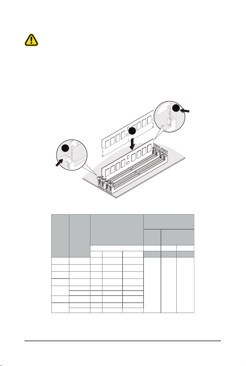
3-4-2 Removing and Installing a Memory Module
Before installing a memory module, make sure to turn off the computer and unplug the power
cord from the power outlet to prevent damage to the memory module.
Be sure to install DDR4 DIMMs on to this motherboard.
Follow these instructions to install a DIMM module:
1. Insert the DIMM memory module vertically into the DIMM slot and push it down.
2. Close the plastic clip at both edges of the DIMM slots to lock the DIMM module.
3. Reverse the installation steps when you want to remove the DIMM module.
2
1
2
3-4-3 DIMM Population Table
Type
RDIMM
RDIMM
RDIMM
RDIMM
RDIMM
3DS
LRDIMM
LRDIMM
3DS
Ranks Per
DIMM and
Data Width
SRx4
SRx8
DRx8
DRx4
QRx 4
8Rx 4
QRx4
QRx4
8Rx4
DIMM
Capacity
(GB)
DIMM Density
4Gb 8Gb
4GB 8GB
8GB 16GB
8GB 16GB
32GB
16GB
N/A
2H-64GB
N/A
4H-128GB
32GB
64GB
N/A
2H-64GB
N/A 4H- 128GB
Speed (MT/s); Voltage (V)
Slot Per Channel (SPC)
DIMM Per Channel (DPC)
1 Slot per
2 Slot per Channel
Channel
1DPC 1DPC 2DPC
8Gb
1.2V
1.2V 1.2V
16GB
32GB
32GB
64GB
2H-128GB
4H-256GB
128GB
2H -128GB
4H-256GB
2933 2933 2666
- 27 - System Hardware Installation
3-5 Removing and Installing the PCI Expansion Card
• Voltages can be present within the server whenever an AC power source is connected. This
voltage is present even when the main power switch is in the off position. Ensure that the system
is powered off and all power sources have been disconnected from the server prior to installing a
PCIe card.
• Failure to observe these warnings could result in personal injury or damage to equipment.
• The PCI riser assembly does not include a riser card or any cabling as standard. To install a
PCIe card, a riser card must be installed.
Follow these instructions to PCI Expansion card:
1. Loosen and remove the thumbscrew on the riser bracket.
2. Remove the screw securing the riser bracket.
3. Lift up the riser bracket out of system.
4. Loosen and remove the screw securing the slot cover from riser bracket.
5. Orient the PCIe card with the riser guide slot and push in the direction of the arrow until the PCIe
card sits in the PCIe card connector.
NOTE:
Some riser brackets allow for single or multiple PCIe cards. Repeat steps 4-5 as necessary.
6. Secure the PCIe card with the screw.
7. Reverse steps 1-3 to install the riser bracket.
3
6
4
1
5
System Hardware Installation - 28 -
1
2
2
3
6
4
5
Available on Selected Models
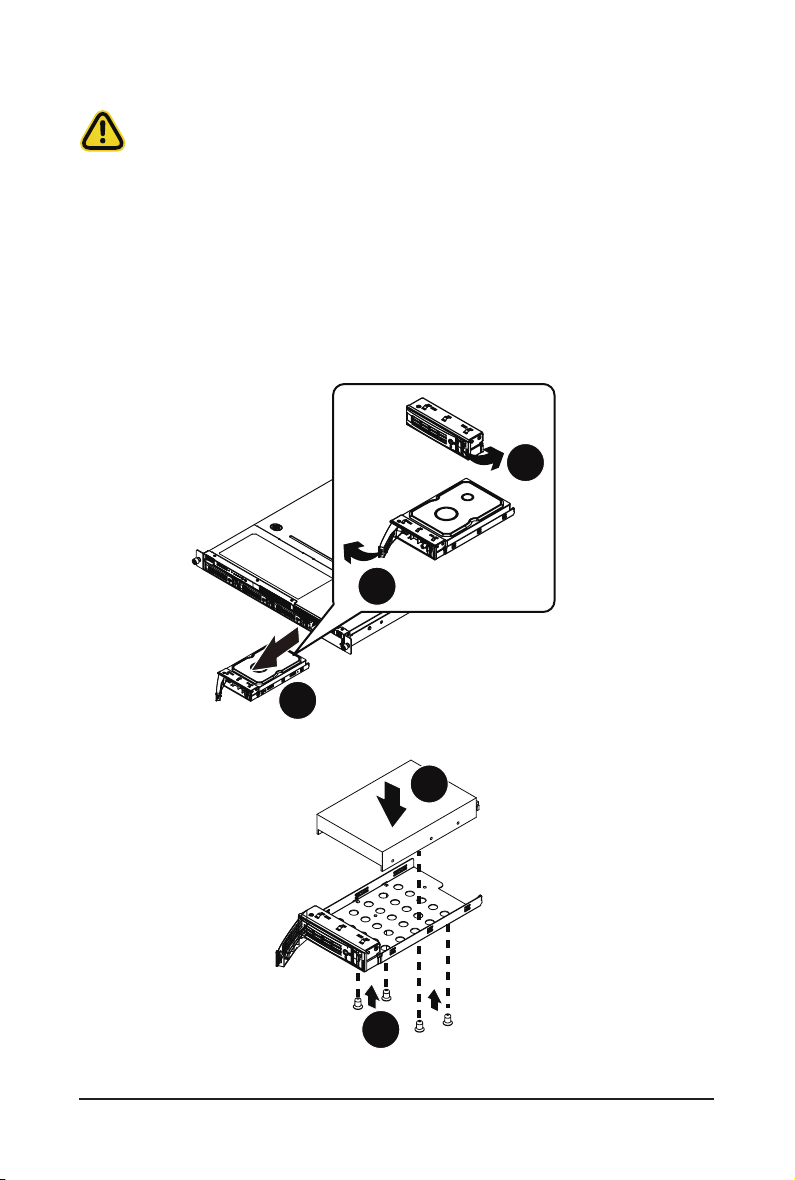
3-6 Removing and Installing the Hard Disk Drive
Read the following guidelines before you begin to install the hard disk drive:
• Take note of the drive tray orientation before sliding it out.
• The tray will not t back into the bay if it is inserted incorrectly.
• Make sure that the HDD is connected to the HDD connector on the backplane.
Follow these instructions to install a hard disk drive:
1. Press the release button.
2. Extend the locking lever.
3. Pull the locking lever in the direction of the arrow to remove the HDD tray.
4. Slide the hard disk into the HDD tray.
5. Install 4 screws to secure the hard drive to the HDD tray.
6. Reinsert the HDD tray into the slot and close the locking lever.
Press
1
Pull
2
3
4
5
- 29 - System Hardware Installation
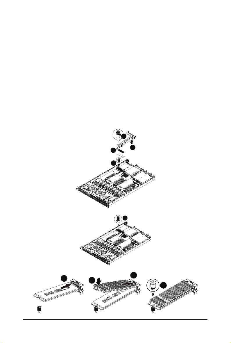
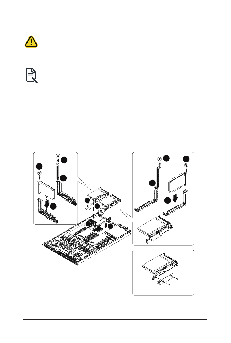
3-7 Installing and Removing an M.2 Solid State Drive
Follow these instructions to install an optional M.2 solid state drive (SSD):
1. Loosen and remove the thumbscrew on the riser bracket.
2. Lift up the screw securing the riser bracket.
3. Loosen and remove the thumbscrew on the M.2 heat sink.Remove the M.2 heat sink and warning
mylar.
4. Loosen and remove the stand-off.
5. Place the stnad off to the dedicated position.
NOTE:
below for proper placement.
6. Place the solid state drive into the M.2 connector.
7. Secure the solid state drive to the motherboard with a single screw.
NOTE:
below for proper placement.
8. Reverse steps 5-7 to remove the solid state drive.
The position of the screw will depend on the size of the SSD. Refer to the second image
The position of the screw will depend on the size of the SSD. Refer to the second image
1
3
4
2
5
6
8
7
9
System Hardware Installation - 30 -
 Loading...