


8
+12V_BUS
C10 place at the AGP connector
C10
D D
AGP_INTR#(2)
AGP_GNT#(2)
AGP_WBF#(2)
AGP_SB_STB#(2)
AGP_MB_8X_DET#(2)
AGP_DBI_HI(2)
AGP_RESET#(2)
C C
B B
A A
AGP_RESET#
AGP_AD_STB1#(2)
AGP_FRAME#(2)
AGP_TRDY#(2)
AGP_STOP#(2)
AGP_PAR(2)
AGP_AD_STB0#(2)
AGP_MB_8X_DET#
10uF_20V
DNI
R3
100R
U6A
R4
SN74ACT86D
180R
COMMON
AGP_TYPEDET#
AGP_GC_8X_DET#
+3.3V_BUS
UNIVERSAL VREFGC CIRCUIT (2X, 4X, 8X)
8
R83 0R
+5V_BUS
147
3
R19
0R
R81
0R
R90
47K
13
12
7
C11
100nF
X7R
1
2
For retail, 1K ohm
pull-down causes
AMD system detects
AGP2X only
+12V, TYPEDET#
short protection
for OEM (1KR)
U6D
SN74ACT86D
7
6
The following grounds should be routed back to their respective regulators and then tied directly to the ground plane with one
GND_RSET
GND_R2SET
C2
100uF_6.3V
Biggest footprint
AGP_TYPEDET#
AGP_GC_8X_DET#
AGP_ST1
AGP_SBA1
AGP_SBA3
AGP_SBA5
AGP_SBA7
AGP_AD30
AGP_AD28
AGP_AD26
AGP_AD24
AGP_C/BE#3
AGP_AD22
AGP_AD20
AGP_AD18
AGP_AD16
AGP_AD15
AGP_AD13
AGP_AD11
AGP_AD9
AGP_C/BE#0
AGP_AD6
AGP_AD4
AGP_AD2
AGP_AD0
+VDDQ_BUS
32
TEST
11
R91
1K
1
2N7002E
Q10
R92 147R
via: GND_PVSS, GND_MPVSS, GND_TPVSS, and GND_A2VSSN. The other ground pins (GND_AVSSN, GND_A2VSSQ,
GND_RSET, GND_R2SET) should be tied to the ground plane directly through one via as close to the pins as possible
without connecting to anything else. If space is an issue it is possible to use one via for two adjacent pins.
Use 47uF Tant. 16V 20% D size (P/N 4230047600),
800mR Max. ESR and Max. ripple 430mA @ 100kHz
or
100uF, Alum. 6.3V 20% 6.3mm dia (P/N 4261010700),
440mR Max. ESR and Max. ripple 230mA @ 100kHz
or
47uF, Alum. 6.3V 20% 5mm dia (P/N 4262047600),
760mR Max. ESR and Max. ripple 150mA @ 100kHz
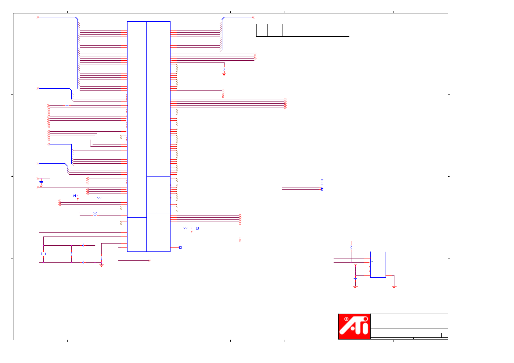
MAGP1
A1
12V
A2
TYPEDET#
A3
GC_DET#/RESEVED
A4
USB-
A5
GND
A6
INTA#
A7
RST#
A8
GNT#
A9
VCC3.3
A10
ST1
A11
MB_DET#/RESERVED
A12
DBI_HI/PIPE#
A13
GND#A13
A14
WBF#
A15
SBA1
A16
VCC3.3#A16
A17
SBA3
A18
SB_STB#
A19
GND#A19
A20
SBA5
A21
SBA7
A22
KEY
A23
KEY#A23
A24
KEY#A24
A25
KEY#A25
A26
AD30
A27
AD28
A28
VCC3.3#A28
A29
AD26
A30
AD24
A31
GND#A31
A32
AD_STB1#
A33
C/BE3#
A34
VDDQ
A35
AD22
A36
AD20
A37
GND#A37
A38
AD18
A39
AD16
A40
VDDQ#A40
A41
FRAME#
A42
KEY#A42
A43
KEY#A43
A44
KEY#A44
A45
KEY#A45
A46
TRDY#
A47
STOP#
A48
PME#
A49
GND#A49
A50
PAR
A51
AD15
A52
VDDQ#A52
A53
AD13
A54
AD11
A55
GND#A55
A56
AD9
A57
C/BE0#
A58
VDDQ#A58
A59
AD_STB0#
A60
AD6
A61
GND#A61
A62
AD4
A63
AD2
A64
VDDQ#A64
A65
AD0
A66
VREFGC
UNIVERSAL_AGP_BUS
AGP_VREFGC
R_AGP8X must be 1%
resistor to provide
350mV +/- 5% on Vref
R_AGP8X
R93
332R
C19
R94
10nF
100R
6
OVRCNT#
5.0V#B3
GND#B5
VCC3.3#B9
GND#B13
DBI_LO/RESERVED
VCC3.3#B16
SB_STB
GND#B19
KEY#B22
KEY#B23
KEY#B24
KEY#B25
VCC3.3#B28
GND#B31
AD_STB1
VDDQ#B34
GND#B37
C/BE2#
VDDQ#B40
KEY#B42
KEY#B43
KEY#B44
KEY#B45
DEVSEL#
VDDQ#B47
PERR#
GND#B49
SERR#
C/BE1#
VDDQ#B52
GND#B55
VDDQ#B58
AD_STB0
GND#B61
VDDQ#B64
VREFCG
USB+
INTB#
REQ#
RBF#
SBA0
SBA2
SBA4
SBA6
IRDY#
5
+3.3V_BUS+5V_BUS+VDDQ_BUS
C5
C8
47uF_6.3V
47uF_6.3V
>=6.3V
>=6.3V
DNI
B1
B2
5.0V
B3
B4
B5
B6
B7
CLK
B8
B9
B10
ST0
B11
ST2
B12
B13
B14
B15
B16
B17
B18
B19
B20
B21
B22
B23
B24
B25
B26
AD31
B27
AD29
B28
B29
AD27
B30
AD25
B31
B32
B33
AD23
B34
B35
AD21
B36
AD19
B37
B38
AD17
B39
B40
B41
B42
B43
B44
B45
B46
B47
B48
B49
B50
B51
B52
B53
AD14
B54
AD12
B55
B56
AD10
B57
AD8
B58
B59
B60
AD7
B61
B62
AD5
B63
AD3
B64
B65
AD1
B66
5
AGP_ST0
AGP_ST2
AGP_SBA0
AGP_SBA2
AGP_SBA4
AGP_SBA6
AGP_AD31
AGP_AD29
AGP_AD27
AGP_AD25
AGP_AD23
AGP_AD21
AGP_AD19
AGP_AD17
AGP_C/BE#2
AGP_C/BE#1
AGP_AD14
AGP_AD12
AGP_AD10
AGP_AD8
AGP_AD7
AGP_AD5
AGP_AD3
AGP_AD1
AGP_AGPREF
4
AGP_SBA[7..0]
AGP_ST[2..0]
AGP_C/BE#[3..0]
AGP_AD[31..0]
R86 0R
4
3
AGP_SBA[7..0] (2)
AGP_ST[2..0] (2)
AGP_C/BE#[3..0] (2)
AGP_AD[31..0] (2)
AGP_AGP/PCICLK (2)
AGP_REQ# (2)
AGP_RBF# (2)
AGP_DBI_LO (2)
AGP_SB_STB (2)
AGP_AD_STB1 (2)
AGP_IRDY# (2)
AGP_DEVSEL# (2)
AGP_AD_STB0 (2)
3
TEST
AGP_AGPREF
AGP_VREFGC
TEST
+VDDQ_BUS
R84 0R
R85 0R
+VDDQ_BUS
1
2
R88 137R
32
1%
Q9
2N7002E1
R89 75.0R
32
2N7002E
Q11
R95 147R
AGP_AGPTEST
1%
R_AGP8X must be 1%
resistor to provide
350mV +/- 5% on Vref
AGP_AGPTEST (2)
Keep stubs short
R_AGP8X
R96
332R
C21
R97
10nF
100R
ATI Technologies Inc.
1 Commerce Valley Drive East
Markham, Ontario
Canada, L3T 7N6
(905) 882-2600
Title
RV280 LP AGP8x 128MB 16Mx16 DDR
Size Document Number Rev
Custom
星期二, 八月
Date: Sheet of
2
12, 2003
105-A165XX-00B
AGP_AGPREFCG (2)
1
1 14
1
1
5
4
3
2
1
Model Name :
GV-R92S128T
Revision 1.0
D D
Component value change history
MODE
Change Item ReasonBOM Rev Date
0.1 06/24 Initial Version
0.2 06/30 Update Design-kit for
PCB Layout
1.0A 07/17 For PVT Pilot-Run
1.0A 07/24 Correct Package
1.0A 07/30 Add second source
1.0A 07/31 Add second source
1.0A 08/01 Add New Game CD
C C
Circuit or PCB layout change for
next version history
PCB Rev
Date Change Item Reason
Update Design-kit for PCB Layout0.2 06/30
07/171.0 Modify PCB silkscreen Rev0.2 => Rev1.0
B B
A A
GIGABYTE
Title
BOM & PCB Modify History
Size Document Number Rev
C
5
4
3
2
Date: Sheet of
星期二, 八月
GV-R92S128T
12, 2003
1
1 1
1.0
8
AGP_AD[31..0]
D D
AGP_C/BE#[3..0](1)
C C
AGP_ST[2..0](1)
AGP_AGPREFCG(1)
AGP_AGPTEST(1)
B B
AGP_C/BE#[3..0]
AGP_AGP/PCICLK(1)
AGP_RESET#(1)
AGP_REQ#(1)
AGP_GNT#(1)
AGP_PAR(1)
AGP_STOP#(1)
AGP_DEVSEL#(1)
AGP_TRDY#(1)
AGP_IRDY#(1)
AGP_FRAME#(1)
AGP_INTR#(1)
AGP_WBF#(1)
AGP_RBF#(1)
AGP_AD_STB0(1)
AGP_AD_STB1(1)
AGP_SB_STB(1)
AGP_SBA[7..0](1)
R36 0R
AGP_SBA[7..0]
AGP_ST[2..0]
AGP_SB_STB#(1)
OSC_IN
AGP_AD_STB0#(1)
AGP_AD_STB1#(1)
AGP_MB_8X_DET#(1)
AGP_DBI_HI(1)
AGP_DBI_LO(1)
TP8
C1205 22pF
R1115
1M
C1206 22pF
C20
100nF
A_R/C_DAC2(11)
A_G/Y_DAC2(11)
A_B/COMP_DAC2(11)
Y2
27_MHZ
2 1
GND_R2SET
+3.3V_BUS
7
AGP_AD0
AGP_AD1
AGP_AD2
AGP_AD3
AGP_AD4
AGP_AD5
AGP_AD6
AGP_AD7
AGP_AD8
AGP_AD9
AGP_AD10
AGP_AD11
AGP_AD12
AGP_AD13
AGP_AD14
AGP_AD15
AGP_AD16
AGP_AD17
AGP_AD18
AGP_AD19
AGP_AD20
AGP_AD21
AGP_AD22
AGP_AD23
AGP_AD24
AGP_AD25
AGP_AD26
AGP_AD27
AGP_AD28
AGP_AD29
AGP_AD30
AGP_AD31
AGP_C/BE#0
AGP_C/BE#1
AGP_C/BE#2
AGP_C/BE#3
AGP_SBA0
AGP_SBA1
AGP_SBA2
AGP_SBA3
AGP_SBA4
AGP_SBA5
AGP_SBA6
AGP_SBA7
AGP_ST0
AGP_ST1
AGP_ST2
R40 715R
R1198 4.7K DNI
R1199 4.7K DNI
6
U1A
K27
AD0
L26
AD1
L25
AD2
L27
AD3
M25
AD4
M26
AD5
N26
AD6
N25
AD7
R26
AD8
R25
AD9
T26
AD10
T25
AD11
U26
AD12
U25
AD13
U27
AD14
V26
AD15
M28
AD16
N29
AD17
N28
AD18
P29
AD19
P28
AD20
R29
AD21
R28
AD22
T28
AD23
V29
AD24
V28
AD25
W29
AD26
W28
AD27
Y29
AD28
Y28
AD29
AA29
AD30
AA28
AD31
P27
C/BEb0
V25
C/BEb1
M29
C/BEb2
T29
C/BEb3
AF29
PCICLK
AG30
RSTb
AE29
REQb
AG28
GNTb
J29
PAR
J28
STOPb
K29
DEVSELb
K28
TRDYb
L29
IRDYb
L28
FRAMEb
AF28
INTAb
AF27
WBFb
AJ26
NC19
AH25
NC18
AC29
RBFb
P25
AD_STBF0
U29
AD_STBF1
AB26
SB_STBF
AE27
SBA0
AD26
SBA1
AC25
SBA2
AC26
SBA3
AA25
SBA4
AA26
SBA5
Y25
SBA6
Y26
SBA7/IDSEL
AD28
ST0
AD29
ST1
AC28
ST2
AB25
SB_STBS
P26
AD_STBS0
U28
AD_STBS1
H29
AGPREF
H28
AGPTEST
AG27
AGP8X_DETb
AB28
DBI_HI
AB29
DBI_LO
AJ21
R2SET
AJ22
C_R
AK22
Y_G
AK21
COMP_B
AG25
H2SYNC
AF25
V2SYNC
AF23
CRT2DDCCLK
AG24
CRT2DDCDAT
AG29
NC34
AH29
NC33
AJ28
XTALIN
AJ29
AH26
AJ27
XTALOUT
TESTEN
STEREOSYNC
RV280
STEREOSYNC
TESTEN
R33
1K
Part 1 of 5
EXT TMDS / GPIO /
PCI/AGPAGP2XCLK
NCSTMDSDAC1
AGP4X/8X
SSC DAC2
STEREOSYNC (7)
GPIO10
GPIO11
GPIO12
GPIO13
GPIO14
GPIO15
GPIO16
ROMCSb
DVOMODE
ZV_LCDDATA0
ZV_LCDDATA1
ZV_LCDDATA2
ZV_LCDDATA3
ZV_LCDDATA4
ZV_LCDDATA5
ZV_LCDDATA6
ZV_LCDDATA7
ZV_LCDDATA8
ZV_LCDDATA9
ZV_LCDDATA10
ZV_LCDDATA11
ZV_LCDDATA12
ROM
ZV_LCDDATA13
ZV_LCDDATA14
ZV_LCDDATA15
ZV_LCDDATA16
ZV_LCDDATA17
ZV_LCDDATA18
ZV_LCDDATA19
ZV_LCDDATA20
ZV_LCDDATA21
ZV_LCDDATA22
ZV_LCDDATA23
ZV_LCDCNTL0
ZV_LCDCNTL1
ZV_LCDCNTL2
ZV_LCDCNTL3
DPLUS
DMINUS
DVIDDCCLK
DVIDDCDATA
HSYNC
VSYNC
VGADDCDATA
VGADDCCLK
AUXWIN
GPIO0
GPIO1
GPIO2
GPIO3
GPIO4
GPIO5
GPIO6
GPIO7
GPIO8
GPIO9
NC35
NC27
NC36
NC28
NC37
NC29
NC39
NC31
NC38
NC30
NC22
NC13
NC23
NC14
NC24
NC15
NC26
NC17
NC25
NC16
TX0M
TX0P
TX1M
TX1P
TX2M
TX2P
TXCM
TXCP
RSET
AJ5
AK4
AJ4
AF4
AG4
AH4
AK3
AJ3
AH3
AG3
AF3
AJ2
AH2
AG2
AF2
AH1
AG1
AH5
AE10
AF5
AE6
AF6
AE7
AG6
AF7
AG8
AF8
AE8
AE9
AF9
AG9
AK7
AJ7
AH8
AJ8
AH9
AJ9
AK9
AH10
AK10
AJ10
AH11
AJ11
AK6
AJ6
AH6
AH7
AE15
AF15
AE16
AF16
AG15
AH15
AH16
AH17
AF17
AG17
AJ17
AH18
AK18
AJ18
AG19
AH19
AJ16
AK16
AH20
AJ20
AF11
NC7
AE12
NC8
AF10
AE11
AJ13
AH13
AJ14
AH14
AJ15
AK15
AK12
AK13
AF13
AE13
AF12
HPD
AK25
R
AJ25
G
AK24
B
AH28
AH27
R39 499R
AJ23
AG26
AF26
AE25
TP10
VID/DVO12
VID/DVO13
VID/DVO14
VID/DVO15
GND_RSET
GPIO0
GPIO1
GPIO2
GPIO3
GPIO4
GPIO5
GPIO6
GPIO7
GPIO8
GPIO9
GPIO10
GPIO11
GPIO12
GPIO13
GPIO14
GPIO15
GPIO16
ROMCS#
DVOMODE
VID/DVO16
VID/DVO17
VID/DVO18
VID/DVO19
VID/DVO20
TP7
5
VSYNC
VGADDCDATA
VGADDCCLK
GPIO[13..0]
R986
10K
24bit-SDR-DVO
DC_Strap1 (7)
DC_Strap2 (7)
DC_Strap3 (7)
DC_Strap4 (7)
GPIO[13..0] (7)AGP_AD[31..0](1)
Mem_Strap1 (7)
Mem_Strap0 (7)
A_R_DAC1 (10)
A_G_DAC1 (10)
A_B_DAC1 (10)
A_HSYNC_DAC1 (10)
A_VSYNC_DAC1 (10)
CRT1DDCDATA (10)
CRT1DDCCLK (10)
4
RSET
R2SET
Mem_Strap2 (7)
3
THE VALUES OF RSET AND R2SET SHOWN IN THE TABLE MAY BE
APPROXIMATE VALUES ONLY (SUITABLE FOR PROTOTYPING)
BEFORE GOING INTO PRODUCTION,CONTACT YOUR ATI
499R
REPRESENTATIVE FOR THE RSET/R2SET VALUES QUALIFIED FOR
715R
MASS PRODUCTION
LCDDATA16 (7)
LCDDATA17 (7)
PAL/NTSC (7)
DC_Strap5 (7)
LCDDATA20 (7)
STEREOSYNC
VGADDCDATA
VGADDCCLK
VSYNC
TESTEN
TDO
TDI
TMS
TCK
TRST
TP1
TP2
TP3
TP4
TP5
OPTION BOUNDARY
SCAN WITH TESTEN
GPIO9
GPIO10
ROMCS#
2
SERIAL EEPROM BIOS
+3.3V_BUS
R21
10K
U11
5
D
6
C
1
S
+3.3V_BUS
7
HOLD
3
W
8
VCC
M25P05-VMN6T
C80
100nF
X7R
1
GPIO8
2
Q
4
VSS
Drop-in without strap change
A A
8
7
6
5
4
3
Pm25LV512-25SC P/N2280002900
ATI Technologies Inc.
1 Commerce Valley Drive East
Markham, Ontario
Canada, L3T 7N6
(905) 882-2600
Title
RV280 LP AGP8x 128MB 16Mx16 DDR
Size Document Number Rev
Custom
星期二, 八月
Date: Sheet of
2
12, 2003
105-A165XX-00B
2 14
1
1
5
D D
4
3
2
1
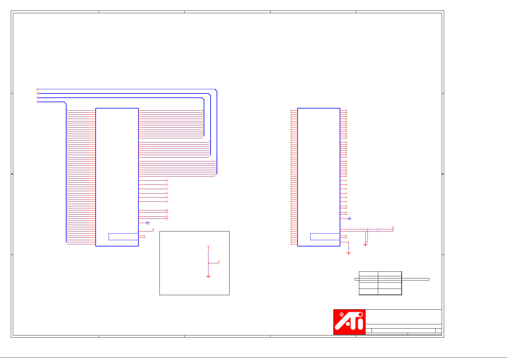
MEMORY CHANNEL A
QSA[7..0](8)
DQMA#[7..0](8)
MAA[13..0](8)
MDA[63..0](8)
C C
B B
A A
QSA[7..0]
DQMA#[7..0]
MAA[13..0]
MDA[63..0]
MDA0
MDA1
MDA2
MDA3
MDA4
MDA5
MDA6
MDA7
MDA8
MDA9
MDA10
MDA11
MDA12
MDA13
MDA14
MDA15
MDA16
MDA17
MDA18
MDA19
MDA20
MDA21
MDA22
MDA23
MDA24
MDA25
MDA26
MDA27
MDA28
MDA29
MDA30
MDA31
MDA32
MDA33
MDA34
MDA35
MDA36
MDA37
MDA38
MDA39
MDA40
MDA41
MDA42
MDA43
MDA44
MDA45
MDA46
MDA47
MDA48
MDA49
MDA50
MDA51
MDA52
MDA53
MDA54
MDA55
MDA56
MDA57
MDA58
MDA59
MDA60
MDA61
MDA62
MDA63
U1B
RV280
DQA1
DQA2
DQA3
DQA4
DQA5
DQA6
DQA7
DQA8
DQA9
DQA10
DQA11
DQA12
DQA13
DQA14
DQA15
DQA16
DQA17
DQA18
DQA19
DQA20
DQA21
DQA22
DQA23
DQA24
DQA25
DQA26
DQA27
DQA28
DQA29
DQA30
DQA31
DQA32
DQA33
DQA34
DQA35
DQA36
DQA37
DQA38
DQA39
DQA40
DQA41
DQA42
DQA43
DQA44
DQA45
DQA46
DQA47
DQA48
DQA49
DQA50
DQA51
DQA52
DQA53
DQA54
DQA55
DQA56
DQA57
DQA58
DQA59
DQA60
DQA61
DQA62
DQA63
Part 2 of 5
ELPIDA
MEMORY INTERFACE
A
G30
F28
F30
E29
D28
D29
D30
K25
K26
J25
J26
G28
G25
G26
G27
C29
B29
B28
C27
C26
B26
C25
B25
E26
F25
E25
F24
E23
D22
F22
E22
C17
B17
C16
B16
C14
B14
C13
B13
E18
F17
E17
D16
F15
E15
F14
E14
A13
C12
A12
B12
C10
B10
C9
B9
E13
F12
E12
F11
E10
F9
E9
F8
DQMAb0
DQMAb1
DQMAb2
DQMAb3
DQMAb4
DQMAb5
DQMAb6
DQMAb7
QSA0
QSA1
QSA2
QSA3
QSA4
QSA5
QSA6
QSA7
RASAb
CASAb
WEAb
CSAb0
CSAb1
CKEA
CLKA0
CLKA0b
CLKA1
CLKA1b
CLKAFB
VREF
DIMA0
DIMA1
MAA0
B24G29
AA0DQA0
MAA1
A24
AA1
MAA2
B23
AA2
MAA3
C23
AA3
MAA4
B21
AA4
MAA5
F21
AA5
MAA6
E21
AA6
MAA7
F20
AA7
MAA8
E20
AA8
MAA9
C21
AA9
MAA10
B22
AA10
MAA11
C22
AA11
MAA12
A25
AA12
MAA13
C24
AA13
DQMA#0
E28
DQMA#1
H26
DQMA#2
A27
DQMA#3
E24
DQMA#4
B15
DQMA#5
E16
DQMA#6
C11
DQMA#7
E11
QSA0
F29
QSA1
H25
QSA2
B27
QSA3
F23
QSA4
C15
QSA5
F16
QSA6
B11
QSA7
F10
RASA#
A19
CASA#
C18
WEA#
F18
CSA#0
E19
CSA#1
F19
CKEA
B19
CLKA0
C20
CLKA#0
B20
CLKA1
B18
CLKA#1
A18
C19
TP11
B8
F26
F13
RASA# (8)
CASA# (8)
WEA# (8)
CSA#0 (8)
CSA#1 (8)
CKEA (8)
CLKA0 (8,9)
CLKA#0 (8,9)
CLKA1 (8,9)
CLKA#1 (8,9)
+VREF
Place close to ASIC ball
Use localized Vref on the memory page
Vref Voltage
+MVDDQ
R265
Re6
499R
R268
Re7
499R
+VREF
MEMORY CHANNEL B
U1C
B6
DQB0
RV280
DQB1
DQB2
DQB3
DQB4
DQB5
DQB6
DQB7
DQB8
DQB9
DQB10
DQB11
DQB12
DQB13
DQB14
DQB15
DQB16
DQB17
DQB18
DQB19
DQB20
DQB21
DQB22
DQB23
DQB24
DQB25
DQB26
DQB27
DQB28
DQB29
DQB30
DQB31
DQB32
DQB33
DQB34
DQB35
DQB36
DQB37
DQB38
DQB39
DQB40
DQB41
DQB42
DQB43
DQB44
DQB45
DQB46
DQB47
DQB48
DQB49
DQB50
DQB51
DQB52
DQB53
DQB54
DQB55
DQB56
DQB57
DQB58
DQB59
DQB60
DQB61
DQB62
DQB63
Part 3 of 5
ELPIDA
MEMORY INTERFACE
B
MEMVMODE
MEMVMODE1
C6
B5
C5
B2
C3
C2
D2
E8
E7
D4
D3
F6
F3
F5
G6
D1
E2
F2
F1
G2
H3
H2
J3
G4
H6
H5
J6
K5
K4
L6
L5
U2
V2
V1
V3
W3
Y2
Y3
AA2
AA3
AB2
AB3
AC2
AD1
AD3
AE1
AE2
U6
U5
U3
V6
W5
W4
Y6
Y5
AA6
AA5
AB6
AB5
AD6
AD5
AE5
AE4
DQMBb0
DQMBb1
DQMBb2
DQMBb3
DQMBb4
DQMBb5
DQMBb6
DQMBb7
RASBb
CASBb
WEBb
CSBb0
CSBb1
CKEB
CLKB0
CLKB0b
CLKB1
CLKB1b
CLKBFB
DIMB0
DIMB1
MEMTEST
QSB0
QSB1
QSB2
QSB3
QSB4
QSB5
QSB6
QSB7
J2
AB0
K3
AB1
K2
AB2
L3
AB3
L2
AB4
M3
AB5
M2
AB6
N5
AB7
M1
AB8
M5
AB9
N3
AB10
P2
AB11
P6
AB12
P5
AB13
A4
E3
G3
J5
W2
AC3
W6
AC6
B4
E5
G1
K6
W1
AD2
V5
AC5
R2
T5
T6
R5
R6
R3
N1
N2
T2
T3
P3
TP12
DNI
2.5V (DDR)
1.8V (DDR)
3.3V (SDR)
+VDDC_CT
Default
B7
C7
G5
AE3
C8
R55
47R
R51 4.7K
R52 4.7K
R53
R54
4.7K
4.7K
DNI
MEMVMODE[1:0] MEMORY IO VOLTAGE
0 1
1 0
1 1
ATI Technologies Inc.
1 Commerce Valley Drive East
Markham, Ontario
Canada, L3T 7N6
(905) 882-2600
Title
RV280 LP AGP8x 128MB 16Mx16 DDR
Size Document Number Rev
Custom
星期二, 八月
5
4
3
2
Date: Sheet of
12, 2003
105-A165XX-00B
1
3 14
1
5
U1D
P18
VDDC#P18
P19
VDDC#P19
U12
VDDC#U12
U13
VDDC#U13
U14
VDDC#U14
U17
VDDC#U17
U18
+VDDC_CT
W12
W13
W14
W17
W18
W19
AC11
AC20
AK19
AE19
AE20
AF20
AG20
AJ19
AF18
AF19
AE18
AE17
AJ12
AH12
AF14
AE14
AG14
AG13
AG12
AF21
AF22
AH21
AF24
AE23
AE21
AE22
AG22
AH22
U19
V12
V13
V14
V17
V18
V19
H10
H13
H15
H17
H19
H22
J1
J23
J24
J27
J4
J7
J8
L8
M4
N4
N7
N8
R1
R4
T4
T7
T8
E27
F4
G10
G13
G15
G22
G7
L23
H20
H11
P8
Y8
VDDC#U18
VDDC#U19
VDDC#V12
VDDC#V13
VDDC#V14
VDDC#V17
VDDC#V18
VDDC#V19
VDDC#W12
VDDC#W13
VDDC#W14
VDDC#W17
VDDC#W18
VDDC#W19
VDDR1#H10
VDDR1#H13
VDDR1#H15
VDDR1#H17
VDDR1#H19
VDDR1#H22
VDDR1#J1
VDDR1#J23
VDDR1#J24
VDDR1#J27
VDDR1#J4
VDDR1#J7
VDDR1#J8
VDDR1#L8
VDDR1#M4
VDDR1#N4
VDDR1#N7
VDDR1#N8
VDDR1#R1
VDDR1#R4
VDDR1#T4
VDDR1#T7
VDDR1#T8
VDDR1#E27
VDDR1#F4
VDDR1#G10
VDDR1#G13
VDDR1#G15
VDDR1#G22
VDDR1#G7
VDDC18#L23
VDDC18#H20
VDDC18#H11
VDDC18#P8
VDDC18#Y8
VDDC18#AC11
VDDC18#AC20
NC
VDDC18#AE19
VDDC18#AE20
NC#AF20
NC#AG20
NC#AJ19
NC#AF18
NC#AF19
NC#AE18
NC#AE17
TPVDD
TPVSS
TXVDDR
TXVDDR#AE14
TXVSSR
TXVSSR#AG13
TXVSSR#AG12
A2VDD
A2VDD#AF22
A2VDDQ
AVDD
AVDD#AE23
A2VSSN
A2VSSN#AE22
A2VSSDI
A2VSSQ
RV280
D D
+MVDDQ
C C
+3.3V_BUS
D31
2.4V
2 1
C56
100nF
X7R
+TPVDD
C58
C57
100nF
4.7uF
>=6.3V
+VDDC_CT
+A2VDD
C62
100nF
X7R
Ceramic
0R on B16
B16 200R
>=6.3V
Ceramic
B B
+MVDDC
L2
1.8uH
C61
4.7uF
>=6.3V
Ceramic
X7R
DNI
DNI
C59
C77
C60
4.7uF CP8C
100nF
100pF
C64
100nF
X7R
DNI
C67
4.7uF
>=6.3V
Ceramic
X7R
DNI
+AVDD
C68
100nF
X7R
X7R
DNI
>=6.3V
Ceramic
+A2VDDQ
C63
4.7uF
4
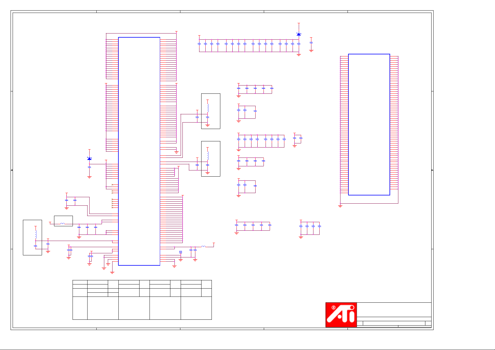
Part 4 of 5
Memory I/O Power
(1.8V/2.5V/3.3V)
I/O level shift power
(1.8V)
Ext. TMDS/
GPIO & Ext.
(1.8V)
TMDS PLL TMDS I/O
(1.8V)
Analog Display Power,
see table below
VDDC
VDDC#AC15
VDDC#AC17
VDDC#AD13
VDDC#AD15
VDDC#M12
VDDC#M13
VDDC#M14
VDDC#M17
VDDC#M18
VDDC#M19
VDDC#N12
VDDC#N13
VDDC#N14
VDDC#N17
VDDC#N18
VDDC#N19
VDDC#P12
VDDC#P13
VDDC#P14
VDDC#P17
VDDR1
VDDR1#A21
VDDR1#AA7
VDDR1#AA8
VDDR1#D11
VDDR1#D14
VDDR1#D17
VDDR1#D8
VDDR1#V4
VDDR1#A28
VDDR1#A3
VDDR1#A9
VDDR1#AA1
VDDR1#AA4
VDDR1#AD4
VDDR1#B1
I/O
POWER
VDDR1#B30
VDDR1#D10
VDDR1#D19
VDDR1#D20
VDDR1#D23
VDDR1#D26
VDDR1#D6
VDDR1#V7
VDDR1#V8
VDDRH0
VDDRH1
VSSRH0
VSSRH1
VDDRH1 - CH B Clock PowerAGP Bus I/O Power
VDDRH0 - CH A Clock Power
(VDDR1)
MPVDD
MPVSS
PVDD
PVSSVDDC18
PLL MPLL
VDDR4
VDDR4#AC9
VDDR4#AD10
VDDR4#AD9
VDDR4#AG10
DVO Power
(1.8V/3.3V)
VDDR3
VDDR3#AC22
VDDR3#AC21
VDDR3#AD21
VDDR3#AC19
VDDR3#AD19
VDDR3#AD7
VDDR3#AC8
(3.3V)
TMDS I/O
Power
VDDP
VDDP#AA24
VDDP#AB27
VDDP#AB30
VDDP#AC23
VDDP#AD27
VDDP#AE30
VDDP#AH30
VDDP#J30
VDDP#M23
VDDP#M24
VDDP#N27
VDDP#N30
VDDP#P23
VDDP#T23
VDDP#T24
(1.5V/3.3V) (1.8V) (1.8V)
VDDP#T27
VDDP#T30
VDDP#V23
VDDP#V24
VDDP#W27
VDDP#W30
VDDP#Y27
AVDDDI
A2VDDDI
AVSSQ
AVSSDI
AVSSN#AD24
AVSSN
3
+VDDC
AC13
AC15
AC17
AD13
AD15
M12
M13
M14
M17
M18
M19
N12
N13
N14
N17
N18
N19
P12
P13
P14
P17
+MVDDQ
A15
A21
AA7
AA8
D11
D14
D17
D8
V4
A28
A3
A9
AA1
AA4
AD4
B1
B30
D10
D19
D20
D23
D26
D6
V7
V8
G19
N6
G18
M6
A7
A6
AK27
AK28Y23
+3.3V_BUS
AC10
AC9
AD10
AD9
AG10
AD22
AC22
AC21
AD21
AC19
AD19
AD7
AC8
AA23
AA24
AB27
AB30
AC23
AD27
AE30
AH30
J30
M23
M24
N27
N30
P23
T23
T24
T27
T30
V23
V24
W27
W30
Y27
AH24
AH23
AJ24
AG23
AD24
AE24
+VDDQ_BUS
TP9
C65
100nF
X7R
C51
100nF
X7R
C53
100nF
X7R
+VDDC
CP9A
8 1
10nF
+MPVDD
+PVDD
B17 200R
C66
4.7uF
>=6.3V
Ceramic
CP9B
7 2
10nF
+VDDC_CT
+VDDC_CT
CP9C
6 3
10nF
L6
1.8uH
C52
4.7uF
>=6.3V
Ceramic
L3
1.8uH
C54
4.7uF
>=6.3V
Ceramic
+VDDC_CT
CP9D
CP3A
CP3C
CP3B
5 4
8 1
6 3
7 2
10nF
10nF
10nF
10nF
+VDDC
C26
100nF
X7R X7R X7R X7R X7R
+3.3V_BUS
CP1A
8 1
10nF
+MVDDQ +MVDDQ
CP5A
8 1
10nF
+MVDDQ
C32
100nF
X7R X7R X7R X7R
+VDDC_CT
CP1C
6 3
10nF
C45
100nF
X7R
Distributed around
+VDDQ_BUS plane
CP4B
CP4A
CP3D
7 2
8 1
5 4
10nF
10nF
10nF
C27
C28
100nF
100nF
C44
CP1B
100nF
7 2
10nF
CP5D
CP5C
CP5B
5 4
6 3
7 2
10nF
10nF
10nF
C33
C34
100nF
100nF
C83
100nF
CP1D
5 4
10nF
X7R
C46
C47
100nF
100nF
X7R X7R X7R X7R
C48
100nF
CP4C
6 3
10nF
C29
100nF
CP6A
8 1
10nF
C35
100nF
CP4D
5 4
10nF
CP6B
7 2
10nF
C49
100nF
C30
100nF
CP2A
CP2B
8 1
7 2
10nF
10nF
CP6C
CP6D
6 3
5 4
10nF
10nF
2
+3.3V_BUS
D30
2.4V
2 1
CP2D
CP2C
5 4
6 3
10nF
10nF
C38
C39
10uf
10uf
PLACE DIRECTLY
UNDERNEATH CHANNEL
A & B SECTION OF ASIC.
+VDDQ_BUS+VDDQ_BUS
CP8A
CP8B
8 1
7 2
10nF
10nF
+VDDC
C23
10uf
At the corner of VDDC plane
CP8D
6 3
5 4
10nF
10nF
1
U1E
F27
VSS#F27
VSS#F7
VSS#G12
VSS#G16
VSS#G21
VSS#G24
VSS#G9
VSS#H12
VSS#H14
VSS#H16
VSS#H18
VSS#H21
VSS#H23
VSS#H27
VSS#H4
VSS#H8
VSS#H9
VSS#K1
VSS#K23
VSS#K24
VSS#K30
VSS#K7
VSS#K8
VSS#L4
VSS#M15
VSS#M16
VSS#M27
VSS#M30
VSS#M7
VSS#M8
VSS#N15
VSS#N16
VSS#N23
VSS#N24
VSS#P15
VSS#P16
VSS#P4
VSS#R12
VSS#R13
VSS#R14
VSS#R15
VSS#R16
VSS#R17
VSS#R18
VSS#R19
VSS#R23
VSS#R24
VSS#R27
VSS#R30
VSS#R7
VSS#R8
VSS#T1
VSS#T12
VSS#T13
VSS#T14
VSS#T15
VSS#T16
VSS#T17
VSS#T18
VSS#T19
VSS#W23
VSS#W24
VSS#W25
VSS#W26
VSS#W7
VSS#W8
VSS#Y4
RV280
Part 5 of 5
CORE GND
F7
G12
G16
G21
G24
G9
H12
H14
H16
H18
H21
H23
H27
H4
H8
H9
K1
K23
K24
K30
K7
K8
L4
M15
M16
M27
M30
M7
M8
N15
N16
N23
N24
P15
P16
P4
R12
R13
R14
R15
R16
R17
R18
R19
R23
R24
R27
R30
R7
R8
T1
T12
T13
T14
T15
T16
T17
T18
T19
W23
W24
W25
W26
W7
W8
Y4
VSS#U15
VSS#U16
VSS#U23
VSS#U4
VSS#U8
VSS#V15
VSS#A16
VSS#A2
VSS#A22
VSS#A29
VSS#AA27
VSS#AA30
VSS#AB1
VSS#AB23
VSS#AB24
VSS#AB4
VSS#AB7
VSS#AB8
VSS#AC12
VSS#AC14
VSS#AC16
VSS#AC18
VSS#AC27
VSS#AC4
VSS#AD12
VSS#AD16
VSS#AD18
VSS#AD25
VSS#AD30
VSS#AE26
VSS#AE28
VSS#AG11
VSS#AG16
VSS#AG18
VSS#AG21
VSS#AG5
VSS#AG7
VSS#AJ1
VSS#AJ30
VSS#AK2
VSS#AK29
VSS#B3
VSS#C1
VSS#C28
VSS#C30
VSS#C4
VSS#D12
VSS#D13
VSS#D15
VSS#D18
VSS#D21
VSS#D24
VSS#D25
VSS#D27
VSS#D5
VSS#D7
VSS#D9
VSS#E4
VSS#E6
VSS#V16
VSS#V27
VSS#V30
VSS#W15
VSS#W16
U15
U16
U23
U4
U8
V15
A10
VSS
A16
A2
A22
A29
AA27
AA30
AB1
AB23
AB24
AB4
AB7
AB8
AC12
AC14
AC16
AC18
AC27
AC4
AD12
AD16
AD18
AD25
AD30
AE26
AE28
AG11
AG16
AG18
AG21
AG5
AG7
AJ1
AJ30
AK2
AK29
B3
C1
C28
C30
C4
D12
D13
D15
D18
D21
D24
D25
D27
D5
D7
D9
E4
E6
V16
V27
V30
W15
W16
+AVDD
Pin Names
A A
5
Voltage
DAC1 VDD A2VSSQ
Usage
DAC1 Band Gap Ref.
Board power
AVDD sourced from VDDC_CT
and ground
thru bead at least 15 mil trace
option(s)
and not longer than 1.5 inch.
AVSSN and AVSSQ with single
via to GND close to the pin.
(80mA)
Matching
Ground
AVSSN
(Noisy)
AVSSQ
+A2VDD
2.5V1.8V
DAC2 VDD
(120mA)
(1) A2VDD regulated source
and A2VSSN return path routed
with at least 15 mil trace and
not longer than 1.5 inch.
AVSSN with single via to GND
at the regulator.
(2) Sourced from VDD thru bead
instead of the regulator
Matching
Ground
A2VSSN
(Noisy)
4
+A2VDDQ
1.8V
DAC2 Band Gap Ref.
Source from AVDD thru bead.
A2VSSQ with sigle via to GND
close to the pin.
Matching
Ground
(Quiet)
+AVDDDI
+A2VDDDI
1.8V
Digital Power for
DAC1 and DAC2
Source from VDDC_CT
thru bead
Matching
Ground
AVSSDI
A2VSSDI
(Digital)(Quiet)
ATI Technologies Inc.
1 Commerce Valley Drive East
Markham, Ontario
Canada, L3T 7N6
(905) 882-2600
Title
RV280 LP AGP8x 128MB 16Mx16 DDR
Size Document Number Rev
Custom
星期二, 八月
3
2
Date: Sheet of
12, 2003
105-A165XX-00B
1
4 14
1

8
Place caps very
close to power pin
D D
+3.3V_BUS
R801
TL431CDBVR
33R
U810
R816
54.9R
4
NC
1
249R
NC
2
3240249000
5 3
1.25V_REF
R814
140R
249R
2.5V_REF
C810
4.7uF
DNI
C C
C15
100nF
7
R813
3.32K
Ry2
R502
3.32K
Rcx2
R108
3.32K
Rpx2
R110
3.32K
Rpx2
C14
100nF
10
12
13
+12V_BUS
411
U811A
3
+
2
-
LM324M
R815 0R
R812 1070R
U811B
5
+
6
-
LM324M
R501 1070R
U811C
+
9
-
LM324M
R107 1070R
U811D
+
-
LM324M
R109 1070R
1
Ry1
7
Rcx1
8
Rpx1
14
Rpx1
R104
0R
+5V_BUS
1
R103
0R MQ814
+A2VDD
+MVDDC
G_VDDC
R503
0R
+3.3V_BUS
1
R105
0R
+3.3V_BUS
1
R106
0R
4
1.5W @ 25'C
3 2
12mW/'C above 25'C
BCP68
25V 1A SOT-223
300mW @ 25'C
2.4mW/'C above 25'C
Q813
2 3
MMBT2222ALT1
40V 600mA SOT-23
4
1.5W @ 25'C
MQ811
3 2
12mW/'C above 25'C
BCP68
25V 1A SOT-223
6
G_MVDDC
G_MVDDC (2)
+A2VDD
C804
10uF_6.3V
+VDDC
C802
10uF_6.3V
+PVDD
C803
10uF_6.3V
Vout = 2.5V
Vout = 1.62V
Vout = 1.8V
5
1.9V
C129
47uF_6.3V
>=6.3V
4
Regulator for VDDC_CT (Core Transform)
and AVDD/A2VDDQ/AVDDDI/A2VDDDI
TXVDDR, LVDDRx, MPVDD
Vin = 3.3V AGP
Vout = 1.8V
Iout = 350mA + 100mA + 50mA = 500mA MAX
Iout = 600mA MAX (with PVDD/TPVDD)
Rct1 Rct2
1K 3240100100
C131
100nF
X7R
603
REG22
LT1117CST
3 2
IN OUT
CASE
ADJ
1
422R1.8V
3240422000 603
499R 3240499000 603
4
3
+VDDC_CT+3.3V_BUS
Required for
stability
R282
1.00K
Rct1
1%
R278
499R
Rct2
1%
2
Regulator for PVDD (Core PLLs)
and optional TPVDD (TMDS PLLs)
Vin = 3.3V AGP
Vout = +1.8V
Iout = 25mA MAX (PVDD only)
Iout = 30mA MAX (PVDD + TPVDD)
The value of resistor were chosen to reduce failure rate caused by
possible defective regulators, i.e., 33R are used instead of 47R or
51R for more start up current. (3.465V - 1.8V) / 33R = 50.5mA
805 package resistor are required for sufficient power rating
(0.1W rating). (3.465V - 1.8V) * 50.5mA = 0.085W; therefore,
smaller resistor value would require 1206 package
+PVDD
+3.3V_BUS
R284
33R
R287
Rvdd
681R
C55
47uF_6.3V
>=6.3V
3 2
REG25
AS432S
1
Rvdd
1%
4
NC
1
NC
R290
2
1.5K
1%
5 3
MRG25
SC431LC5SK-1
ALT
1
Regulator For A2VDD (2nd DACs)
+VDDC_CT
C801
10uF_6.3V
Vout = 1.8V
Vin = +3.3V AGP
Vout = 2.5V
Iout = 150mA MAX
A2VDD might not be
needed if VDD can
provide stable 2.5V
REG24
Rpx1 Rpx2Range
REG6
AS432S
1K
3240100100
Rcx1 Rcx2+VDDC
1K
3240100100
C506
100nF
MREG6
SC431LC5SK-1
+12V_BUS
1.8V 1.805V ~ 1.827V
B B
Buffered Shount Regulator for VDDC
Vin = 3.3V
Vout = 1.62V or Adjustable
Iout = 3A MAX
Range
1.62V 1.619V ~ 1.635V
G_VDDC
A A
1
3 2
8
2.21K
3240221100
Rc1 Rc2
3.32K
3240332100
OPTIONAL
+VDDC
R504
750R
/.25W
R505
3.32K
1%
4
NC
1
NC
2
5 3
R506
2K
1%
7
Rc1
Rc2
These dummy resistors are placed
under the diodes to avoid PCB heat
damage due to hot diodes.
R554
R553
0R
R552
0R
0R
Q1 Pin2/4 should be soldered to
board for heat dissipation and a
GND fill area.
+VDDC_Source
C501
C504
470uF_10V
100nF
6
R551
0R
4
1
1.75W @ 25'C
Q1
MTD3055V
32
G_VDDC
1N5400
1N5400
AVDD/A2VDDQ (1st DAC & 2nd DAC Band Gap)
TPVDD
+VDDC_CT
+3.3V_BUS
D6
21
D7
21
+VDDC
C502
470uF_10V
C503
470uF_10V
4
3
C505
100nF
5
B27 200R
B29 200R
B25 200R
1
VIN
3
SHDN
C139
100nF
X7R
A2VDD and A2VSSN routed with at least 15
mil trace and not longer than 1.5 inch.
A2VSSN with signle via to GND at the
regulator
+AVDD
+A2VDDQ
+TPVDD
Title
Size Document Number Rev
Custom
Date: Sheet of
2
+A2VDD+3.3V_BUS
5
VOUT
4
BYPASS
GND
2.5V
2
A2VDD
TC1185
ATI Technologies Inc.
1 Commerce Valley Drive East
Markham, Ontario
Canada, L3T 7N6
(905) 882-2600
RV280 LP AGP8x 128MB 16Mx16 DDR
星期二, 八月
12, 2003
105-A165XX-00B
1
5 14
1

8
D D
Voltage Req.
+MVDDC
3.3V
[-0.02V/+0.02V]
+MVDDQ
C C
B B
Rmx1
1.07K
0R2.5V
P/N 3230000000
Rqx1 Rqx2Voltage Req.
0R2.5V
P/N 3230000000
2.5V_REF2
C820
10uf
DNI
TL431CDBVR
7
+3.3V_BUS
Rmx2
3.32K
DNI
DNI
+3.3V_BUS
R820
33R
U800
4
NC
1
NC
R805
2
54.9R
5 3
R803
140R
+12V_BUS
3
2
R112 0R
12
13
R818
3.32K
Rmx2
5
6
R821
3.32K
Rqx2
10
9
411
U801A
+
1
-
LM324M
U801D
+
14
-
LM324M
R817 1070R
U801B
+
7
-
LM324M
R819 0R
U801C
+
8
-
LM324M
6
Place caps very
close to power pin
C13
C12
100nF
100nF
G_MVDDC
G_MVDDC G_MVDDQ
R100
0R
+MVDDC
5
Rmx1
G_MVDDQ
R101
0R
+MVDDQ
Rqx1
+3.3V_BUS
1
R102
0R
+MPVDD
Q802
CMPT3904
2 3
+MVDDC +MVDDQ
+3.3V_BUS
C805
10uF_6.3V
L4
1.8uH
4
Buffered Shunt Regulator for MVDDQ & VDDR1
Vin = 3.3V AGP
Vout = 2.5V
Iout = 1200mA MAX
Iout = 1000mA Est. MAX
+MVDDC
Type
Voltage Req.
Elpida
[-0.09V/+0.18V]
2.5V
2.6V
1
3 2
C130
47uF_6.3V
L5
1.8uH
REG23
AS432S
C132
100nF
X7R
Rq1
681R
1K
4.75K
C136
100nF
+3.3V_BUS
4
1
+12V_BUS
5 3
Q25
MTD3055V
32
32406810001.8V
3240100100
3240475100
MRG23
SC431LC5SK-1
4
NC
1
NC
2
G_MVDDQ
Rq2
1.5K
1K
R277
750R
/.25W
+MVDDQ
***
C127
470uF_6.3V
***
3
Buffered Shount Regulator for MVDDC
Vin = 5V
Vout = 3.3V
Iout = 1.4A MAX
3230015200
3240100100
32404321004.32K
Hynix
Sumsung
Voltage Req.
3.22V
[-0.04V/+0.04V]
3.34V
[-0.04V/+0.04V]
3.45V
[-0.04V/+0.04V]
2.56V
[-0.03V/+0.03V]
OPTIONAL OPTIONAL
R279
1.00K
Rq1
1%
R283
1.00K
Rq2
1%
1
Q34 Pin2/4 should be soldered to
board for heat dissipation and a
GND fill area.
+MVDDC_Source
C1035
47uF_6.3V
G_MVDDC
3 2
2
Rm1
4.32K
P/N 3240432100
4.32K
P/N 3240432100 P/N 3250243100
2.55K
P/N 3240255100
+12V_BUS
C1037
100nF
REG18
MREG5
SC431LC5SK-1
AS432S
+5V_BUS
4
Q34
MTD3055V
32
G_MVDDC
C1036
1
100nF
R949
750R
/.25W
4
NC
1
NC
2
5 3
Rm2
2.74K
P/N 3240274100
2.55K
P/N 3240255100P/N 3240432100
2.43K4.32K
2.43K
P/N 3250243100
+MVDDC+MVDDQ
G_MVDDC (2)
R958
3.32K
Rm1
1%
R960
2K
Rm2
1%
+MVDDC
1 square inch pad size
Buffered Shount Regulator for MPVDD
Vin = 3.3V
Vout = 1.8V
Iout = 10mA MAX
MRG26
SC431LC5SK-1
OPTIONAL
+3.3V_BUS
R285
75R
REG26
AS432S
3 2
+MPVDD
R288
681R
1%
1
4
NC
1
NC
R291
2
1.5K
1%
5 3
C1033
100nF
1
+MVDDC
C105
470uF_10V
A A
ATI Technologies Inc.
1 Commerce Valley Drive East
Markham, Ontario
Canada, L3T 7N6
(905) 882-2600
Title
RV280 LP AGP8x 128MB 16Mx16 DDR
Size Document Number Rev
Custom
星期二, 八月
8
7
6
5
4
3
Date: Sheet of
2
12, 2003
105-A165XX-00B
6 14
1
1

8
GPIO[13..0]
GPIO[13..0](2)
D D
C C
LCDDATA16(2)
LCDDATA17(2)
LCDDATA20(2)
32
SW1B
DIP_SWX2
R250 0R
STEREOSYNC(2)
Mem_Strap0(2)
Mem_Strap1(2)
Mem_Strap2(2)
B B
GPIO0
GPIO1
GPIO2
GPIO3
GPIO11
GPIO12
GPIO13
GPIO9
GPIO8
GPIO4
GPIO5
GPIO6
GPIO7
7
STRAP G
STRAP H
STRAP J
STRAP K
STRAP L
STRAP M
STRAP N
STRAP O
STRAP A
STRAP D
STRAP E
STRAP F
STRAP B
STRAP R
STRAP S
STRAP T
STRAP P
R201 10K DNI
R202 10K
R203 10K DNI
R204 10K
R205 10K DNI
R206 10K
R207 10K DNI
R208 10K
R209 10K
R210 10K
R211 10K
R212 10K
R213 10K
R214 10K
R215 10K
R216 10K DNI
R217 10K DNI
R218 10K
R219 10K DNI
R220 10K
R221 10K DNI
R222 10K
R223 10K DNI
R224 10K
R225 10K DNI
R226 10K
R227 10K DNI
R228 10K
R229 10K
R230 10K DNI
R231 10K
R232 10K DNI
R233 10K DNI
R234 10K
R235 10K DNI
R236 10K
R237 10K DNI
R238 10K
R239 10K DNI
R240 10K
6
+3.3V_BUS
STRAPS
AGPFBSKEW(1:0)
X1CLK_SKWE(1:0)
DNI
DNI
DNI
ROMIDCFG(3:0)
ID_DISABLE
BUSCFG(2:0)
VGA_DISABLE
MULTIFUNC(1:0)
VIP_DEVICE
STRAP P INTERRUPT
LOW
ENABLED (DEFAULT)
DISABLED
HIGH
PIN
GPIO(1:0)
GPIO(3:2)
GPIO(9,13:11)
GPIO(8)
GPIO(6:4)
GPIO(7)
LCDDATA(17:16)
LCDDATA(20)
STRAP T
5
4
OPTION STRAPS
DESCRIPTION
AGP 1x clock feedback phase adjustment wrt refclk(cpuclk)
00 - refclk slightly earlier then feedback
01 - refclk 1 tap earlier then feedback
10 - refclk 1 tap later then feedback
11 - refclk 2 taps earlier then feedback clock
Clock phase adjustment between x1 clk and x2clk
00 - 0 tap delay
01 - 1 tap delay
10 - 2 taps delay
11 - 3 taps delay
If no ROM attached, comtrols chip IDis. If rom attached identifies ROM type
0000 - No ROM, CHG_ID=0
0001 - No ROM, CHG_ID=1
0100 - reserved
0110 - reserved
1000 - Parallel ROM, chip IDis from ROM
1001 - Serial AT25F1024 ROM (Atmel), chip IDis from ROM
1010 - Serial AT45DB011 ROM (Atmel), chip IDis from ROM
1011 - Serial M25P05/10 ROM (ST), chip IDis from ROM
1100 - Reserved
1100 - Serial NX25F011B ROM (ISSI), chip IDis from ROM
0 - Normal operation
1 - Shuts the chip down by not responding to any config cycles
In a system with two graphics chips, one on the motherboard,
the other on add-in card, the strap can be used to disable one of the two throught a jumper.
Controls bus type, CLK PLL select, and IDSEL
000 - 1.5V BUS -> AGP 4x, PLL clk, IDSEL=AD16
000 - 3.3V BUS -> AGP 1x/2x, PLL clk, IDSEL=AD16
001 - 1.5V BUS -> AGP 4x, PLL clk, IDSEL=AD17
001 - 3.3V BUS -> AGP 1x/2x, PLL clk, IDSEL=AD17
010 - 1.5V BUS -> AGP 1x/2x, PLL clk, IDSEL=AD16
010 - 3.3V BUS -> AGP 1x/2x, PLL clk, IDSEL=AD16
011 - 1.5V BUS -> AGP 1x/2x, PLL clk, IDSEL=AD17
011 - 3.3V BUS -> AGP 1x/2x, PLL clk, IDSEL=AD17
100 - PCI 66MHz, PLL clk
101 - PCI 33MHz, 3.3v, REF clk
110 - 1.5V BUS -> AGP 1x, REF clk, IDSEL=AD16
110 - 3.3V BUS -> AGP 1x, REF clk, IDSEL=AD16
111 - 1.5V BUS -> AGP 1x, REF clk, IDSEL=AD17
111 - 3.3V BUS -> AGP 1x, REF clk, IDSEL=AD17
Note that for AGP configurations GPIO(4) acts as the IDSEL strap.
For PCI it acts as the PLL bypass (33 or 66MHz) strap.
0 - VGA controller capabillity enabled.
1 - The device will not be recognized as the systemis VGA controller.
Multi-function device select
00 - single function device.
01 - two function device. No AGP in either function
10 - two function device. AGP only in function 0
11 - two function device. AGP in both functions
If BUSCFG pin based straps are set to PCI, then AGP will not be enabled in any function.
See AGP function table below for detail on AGP ability claims.
Indicates if any slave VIP host devices drove this in low during reset.
0 - Slave VIP host port devices present
1 - No slave VIP host port devices reporting presence during reset
3
DEFAULT
00
(internal pull-down)
00
(internal pull-down)
1100
0
(internal pull-down)
000
(internal pull-down)
0
10
0
2
1
0
DESCRIPTION
Internal TMDS Enabled
0 - Disabled
1 - Enabled
Video Capture Enabled
0 - Disabled
1 - Enabled
DAC2 Off
DAC2 On as CRT
DAC2 On as TVOUT
DAC2 On as TVOUT and CRT
0 - PAL (on board resistor pull-down and switch closed)
1 -NTSC (on board resistor pull-up)
ATI Technologies Inc.
1 Commerce Valley Drive East
Markham, Ontario
Canada, L3T 7N6
(905) 882-2600
Title
RV280 LP AGP8x 128MB 16Mx16 DDR
Size Document Number Rev
Custom
星期二, 八月
3
Date: Sheet of
2
12, 2003
105-A165XX-00B
7 14
1
1
STRAPS
PIN
DC_STRAP1 LCDDATA12
Daughter Card Straps
DC_Strap2 (2)
7
+3.3V_BUS
41
SW1A
DIP_SWX2
PAL/NTSC (2)
6
+3.3V_BUS
R582 10K
R578 10K
R574 10K
DC_Strap5(2)
DC_Strap3(2) DC_Strap4 (2)
DC_Strap1(2)
A A
R575 10K
R579 10K
R583 10K
8
Switch-JUMPER
JU1
1
2
3
Header_3_Pin_1X3
P1
PLUG
R584 10K
R580 10K
R576 10K
R577 10K
R581 10K
R585 10K
DC_STRAP2 LCDDATA13
DC_STRAP4 LCDDATA15 DAC2 ConfigurationDC_STRAP5 LCDDATA19
0 0
0 1
1
1 1
DC_STRAP6 LCDDATA18 TVO Standard Default (Resistor pull-up and switch short to GND)
5
4

5
4
3
2
1
MDA[63..0]
TERMINATION FOR
MEMORY
CHANNEL A
D D
C C
Proper Termination of QSA?
MDA[63..0](3)
QSA[7..0]
QSA[7..0](3)
MDA0
RP117D 56R
MDA1
RP117C 56R63
MDA2
RP117B 56R
MDA3
RP117A 56R
MDA4
RP118D 56R54
MDA5
RP118C 56R
MDA6
RP118B 56R
MDA7
RP118A 56R
MDA8
RP119D 56R5 4
MDA9
RP119C 56R
MDA10
RP119B 56R
MDA11
RP119A 56R8 1
MDA12
RP120A 56R
MDA13
RP120B 56R
MDA14
RP120C 56R63
MDA15
RP120D 56R
MDA16
RP121D 56R
MDA17
RP121C 56R
MDA18
RP121B 56R72
MDA19
RP121A 56R
MDA20
RP122D 56R
MDA21
RP122C 56R63
MDA22
RP122B 56R
MDA23
RP122A 56R
MDA24
RP123A 56R81
MDA25
RP123B 56R
MDA26
RP123C 56R
MDA27
RP123D 56R
MDA28
RP124D 56R5 4
MDA29
RP124C 56R
MDA30
RP124B 56R
MDA31
RP124A 56R8 1
MDA32
RP127A 56R
MDA33
RP127B 56R
MDA34
RP127C 56R6 3
MDA35
RP127D 56R
MDA36 M_MDA36
RP128A 56R
MDA37
RP128B 56R
MDA38
RP128C 56R6 3
MDA39
RP128D 56R
MDA40
RP125D 56R
MDA41
RP125C 56R6 3
MDA42 M_MDA42
RP125B 56R
MDA43
RP125A 56R
MDA44
RP126D 56R5 4
MDA45
RP126C 56R
MDA46
RP126B 56R
MDA47
RP126A 56R
MDA48
RP129A 56R8 1
MDA49
RP129B 56R
MDA50
RP129C 56R
MDA51
RP129D 56R5 4
MDA52
RP130A 56R
MDA53
RP130B 56R
MDA54
RP130C 56R6 3
MDA55
RP130D 56R
MDA56
RP131A 56R
MDA57
RP131B 56R
MDA58
RP131C 56R63
MDA59
RP131D 56R
MDA60
RP132D 56R
MDA61
RP132C 56R6 3
MDA62
RP132B 56R
MDA63
RP132A 56R
QSA0
R759 0R
QSA1
R760 0R
QSA2
R761 0R
QSA3
R762 0R
QSA4
R764 0R
QSA5
R763 0R
QSA6
R765 0R
QSA7
R766 0R
6 3
7 2
6 3
7 2
8 1
7 2
5 4
8 1
7 2
5 4
5 4
7 2
8 1
6 3
7 2
8 1
7 2
6 3
8 1
7 2
5 4
5 4
7 2
8 1
M_MDA0
54
M_MDA1
M_MDA2
72
M_MDA3
81
M_MDA4
M_MDA5
63
M_MDA6
72
M_MDA7
81
M_MDA8
M_MDA9
M_MDA10
M_MDA11
M_MDA12
81
M_MDA13
72
M_MDA14
M_MDA15
54
M_MDA16
54
M_MDA17
63
M_MDA18
M_MDA19
81
M_MDA20
54
M_MDA21
M_MDA22
72
M_MDA23
81
M_MDA24
M_MDA25
72
M_MDA26
63
M_MDA27
54
M_MDA28
M_MDA29
M_MDA30
M_MDA31
M_MDA32
M_MDA33
M_MDA34
M_MDA35
M_MDA37
M_MDA38
M_MDA39
M_MDA40
M_MDA41
M_MDA43
M_MDA44
M_MDA45
M_MDA46
M_MDA47
M_MDA48
M_MDA49
M_MDA50
M_MDA51
M_MDA52
M_MDA53
M_MDA54
M_MDA55
M_MDA56
81
M_MDA57
72
M_MDA58
M_MDA59
54
M_MDA60
M_MDA61
M_MDA62
M_MDA63
M_MDA[63..0]
SERIES Resistors
M_QSA0
M_QSA1
M_QSA2
M_QSA3
M_QSA4
M_QSA5
M_QSA6
M_QSA7
M_MDA[63..0] (9)
For Bi-Directional signals,
Series resistors should be
placed close to the memory
M_QSA[7..0]
M_QSA[7..0] (9)
CLOCK
terminations
Change from 1:1 spacing to at least a
2.5:1 spacing between the pair
These resistors and caps must be placed to minimize any stubs. These
must also be placed after the memory
CLKA0(3,9)
CLKA#0(3,9)
CLKA1(3,9)
CLKA#1(3,9)
M_CLKA0
M_CLKA0 (3,9)
M_CLKA#0
M_CLKA#0 (3,9)
M_CLKA1
M_CLKA1 (3,9)
M_CLKA#1
M_CLKA#1 (3,9)
R797
56R
C778
10nF
R798
56R
R799
56R
C779
10nF
R800
56R
M_DQMA#[7..0]
M_DQMA#[7..0](9)
B B
M_MAA[13..0]
M_MAA[13..0](9)
M_RASA#(9)
M_CASA#(9)
M_WEA#(9)
M_CSA#0(9)
M_CSA#1(9)
M_CKEA(9)
A A
5
4
M_RASA#
M_CASA#
M_WEA#
M_CSA#0
M_CSA#1
M_CKEA
M_DQMA#0
M_DQMA#1
M_DQMA#2
M_DQMA#3
M_DQMA#4
M_DQMA#5
M_DQMA#6
M_DQMA#7
M_MAA0
M_MAA1
M_MAA2
M_MAA3
M_MAA4
M_MAA5
M_MAA6
M_MAA7
M_MAA8
M_MAA9
M_MAA10
M_MAA11
M_MAA12
M_MAA13
R775 56R
R776 56R
R777 56R
R778 56R
R780 56R
R779 56R
R781 56R
R782 56R
RP137A 0R
8 1
RP137B 0R
7 2
RP137C 0R6 3
RP137D 0R
5 4
RP138C 0R
RP138B 0R72
RP138A 0R
RP139A 0R
RP139B 0R7 2
RP139C 0R
RP138D 0R
RP139D 0R
RP140C 0R63
RP140D 0R
RP142B 0R
RP142C 0R63
RP142D 0R
RP142A 0R
RP140A 0R
RP140B 0R72
8 1
6 3
5 4
63
81
54
54
72
54
81
81
DQMA#0
DQMA#1
DQMA#2
DQMA#3
DQMA#4
DQMA#5
DQMA#6
DQMA#7
MAA0
MAA1
MAA2
MAA3
MAA4
MAA5
MAA6
MAA7
MAA8
MAA9
MAA10
MAA11
MAA12
MAA13
RASA# (3)
CASA# (3)
WEA# (3)
CSA#0 (3)
CSA#1 (3)
CKEA (3)
DQMA#[7..0]
MAA[13..0]
3
DQMA#[7..0] (3)
MAA[13..0] (3)
For Uni-Directional
signals, Series
resistors should be
placed close to the
ASIC
<Variant Name>
2
ATI Technologies Inc.
1 Commerce Valley Drive East
Markham, Ontario
Canada, L3T 7N6
(905) 882-2600
Title
RV280 LP AGP8x 128MB 16Mx16 DDR
Size Document Number Rev
Custom
星期二, 八月
Date: Sheet of
12, 2003
105-A165XX-00B
1
8 14
1

8
M_DQMA#[7..0](8)
D D
M_QSA[7..0](8)
C C
M_MAA[13..0](8)
B B
M_DQMA#[7..0]
M_QSA[7..0]
M_CLKA#0(3,8)
M_CLKA#1(3,8)
M_CLKA0(3,8)
M_CLKA1(3,8)
M_CKEA(8)
M_WEA#(8)
M_CASA#(8)
M_RASA#(8)
M_CSA#0(8)
M_CSA#1(8)
M_MAA[13..0]
M_DQMA#0
M_DQMA#1
M_DQMA#2
M_DQMA#3
M_DQMA#4
M_DQMA#5
M_DQMA#6
M_DQMA#7
M_QSA0
M_QSA1
M_QSA2
M_QSA3
M_QSA4
M_QSA5
M_QSA6
M_QSA7
M_CLKA0#
M_CLKA1#
M_CLKA0
M_CLKA1
M_CKEA
M_WEA#
M_CASA#0
M_RASA#0
M_CSA#0
M_CSA#1
M_MAA0
M_MAA1
M_MAA2
M_MAA3
M_MAA4
M_MAA5
M_MAA6
M_MAA7
M_MAA8
M_MAA9
M_MAA10
M_MAA11
M_MAA12
M_MAA13
M_MDA[63..0](8)
7
C418
100nF
M_MAA0
M_MAA1
M_MAA2
M_MAA3
M_MAA4
M_MAA5
M_MAA6
M_MAA7
M_MAA8
M_MAA9
M_MAA10
M_MAA11
M_CLKA0
M_CLKA#0
M_CKEA
M_CSA#0
M_RASA#0
M_CASA#0
M_WEA#
M_QSA3
M_QSA1
M_DQMA#3
M_DQMA#1
M_MAA13
M_MAA12
C566
100nF
+VREF_U33
M_MAA0
M_MAA1
M_MAA2
M_MAA3
M_MAA4
M_MAA5
M_MAA6
M_MAA7
M_MAA8
M_MAA9
M_MAA10
M_MAA11
M_CLKA0
M_CLKA0#
M_CKEA
M_CSA#0
M_RASA#0
M_CASA#0
M_WEA#
M_QSA0
M_QSA2
M_DQMA#0
M_DQMA#2
M_MAA13
M_MAA12
6
+MVDDQ
+MVDDQ
+VREF_U30+VREF_U29
49
C420
100nF
M_MAA0
29
M_MAA1
30
M_MAA2
31
M_MAA3
32
M_MAA4
35
M_MAA5
36
M_MAA6
37
M_MAA7
38
M_MAA8
39
M_MAA9
40
M_MAA10
28
M_MAA11
41
M_CLKA1
45
M_CLKA1#
46
M_CKEA
44
M_CSA#0
24
M_RASA#0
23
M_CASA#0
22
M_WEA#
21
M_QSA7
16
M_QSA5
51
M_DQMA#7
20
M_DQMA#5
47
M_MAA13
26
M_MAA12
27
+MVDDQ+MVDDQ
C569
100nF
+VREF_U34
49
M_MAA0
29
M_MAA1
30
M_MAA2
31
M_MAA3
32
M_MAA4
35
M_MAA5
36
M_MAA6
37
M_MAA7
38
M_MAA8
39
M_MAA9
40
M_MAA10
28
M_MAA11
41
M_CLKA1
45
M_CLKA1#
46
M_CKEA
44
M_CSA#0
24
M_RASA#0
23
M_CASA#0
22
M_WEA#
21
M_QSA4
16
M_QSA6
51
M_DQMA#4
20
M_DQMA#6
47
M_MAA13
26
M_MAA12
27
U29
49
VREF
29
A0
30
A1
31
A2
32
A3
35
A4
36
A5
37
A6
38
A7
39
A8
40
A9
28
A10/AP
41
A11
45
CK
46
CK
44
CKE
24
CS
23
RAS
22
CAS
21
WE
16
LDQS
51
UDQS
20
LDM
47
UDM
26
BA0
27
BA1
1MX16X4
64MB
U33
49
VREF
29
A0
30
A1
31
A2
32
A3
35
A4
36
A5
37
A6
38
A7
39
A8
40
A9
28
A10/AP
41
A11
45
CK
46
CK
44
CKE
24
CS
23
RAS
22
CAS
21
WE
16
LDQS
51
UDQS
20
LDM
47
UDM
26
BA0
27
BA1
1MX16X4
64MB
M_MDA31 M_MDA63
2
DQ0
M_MDA30
4
DQ1
M_MDA29
5
DQ2
M_MDA28
7
DQ3
M_MDA27
8
DQ4
M_MDA26
10
DQ5
M_MDA25
11
DQ6
M_MDA24
13
DQ7
M_MDA15
54
DQ8
M_MDA14
56
DQ9
M_MDA13
57
DQ10
M_MDA12
59
DQ11
M_MDA11
60
DQ12
M_MDA10
62
DQ13
M_MDA9
63
DQ14
M_MDA8
65
DQ15
14
NC
17
NC#17
19
NC#19
25
NC#25
M_CSA#1 M_CSA#1
42
NC#42
43
NC#43
+MVDDC +MVDDC
50
NC#50
53
NC#53
1
VDD
18
VDD#18
33
VDD#33
3
VDDQ
9
VDDQ#9
15
VDDQ#15
55
VDDQ#55
61
VDDQ#61
34
VSS
48
VSS#48
66
VSS#66
6
VSSQ#6
12
VSSQ#12
52
VSSQ
58
VSSQ#58
64
VSSQ#64
M_MDA0
2
DQ0
M_MDA1
4
DQ1
M_MDA2
5
DQ2
M_MDA3
7
DQ3
M_MDA4
8
DQ4
M_MDA5
10
DQ5
M_MDA6
11
DQ6
M_MDA7
13
DQ7
M_MDA16
54
DQ8
M_MDA17
56
DQ9
M_MDA18
57
DQ10
M_MDA19
59
DQ11
M_MDA20
60
DQ12
M_MDA21
62
DQ13
M_MDA22
63
DQ14
M_MDA23
65
DQ15
14
NC
17
NC#17
19
NC#19
25
NC#25
42
NC#42
43
NC#43
50
NC#50
53
NC#53
1
VDD
18
VDD#18
33
VDD#33
3
VDDQ
9
VDDQ#9
15
VDDQ#15
55
VDDQ#55
61
VDDQ#61
34
VSS
48
VSS#48
66
VSS#66
6
VSSQ#6
12
VSSQ#12
52
VSSQ
58
VSSQ#58
64
VSSQ#64
Channel A Bottom UpChannel A Bottom Down
U30
VREF
A0
A1
A2
A3
A4
A5
A6
A7
A8
A9
A10/AP
A11
CK
CK
CKE
CS
RAS
CAS
WE
LDQS
UDQS
LDM
UDM
BA0
BA1
1MX16X4
64MB
U34
VREF
A0
A1
A2
A3
A4
A5
A6
A7
A8
A9
A10/AP
A11
CK
CK
CKE
CS
RAS
CAS
WE
LDQS
UDQS
LDM
UDM
BA0
BA1
1MX16X4
64MB
Channel A Top UpChannel A Top Down
NC#17
NC#19
NC#25
NC#42
NC#43
NC#50
NC#53
VDD#18
VDD#33
VDDQ#9
VDDQ#15
VDDQ#55
VDDQ#61
VSS#48
VSS#66
VSSQ#6
VSSQ#12
VSSQ#58
VSSQ#64
NC#17
NC#19
NC#25
NC#42
NC#43
NC#50
NC#53
VDD#18
VDD#33
VDDQ
VDDQ#9
VDDQ#15
VDDQ#55
VDDQ#61
VSS#48
VSS#66
VSSQ#6
VSSQ#12
VSSQ
VSSQ#58
VSSQ#64
DQ10
DQ11
DQ12
DQ13
DQ14
DQ15
VDDQ
VSSQ
DQ10
DQ11
DQ12
DQ13
DQ14
DQ15
5
2
DQ0
M_MDA62
4
DQ1
M_MDA61
5
DQ2
M_MDA60
7
DQ3
M_MDA59
8
DQ4
M_MDA58
10
DQ5
M_MDA57
11
DQ6
M_MDA56
13
DQ7
M_MDA47
54
DQ8
M_MDA46
56
DQ9
M_MDA45
57
M_MDA44
59
M_MDA43
60
M_MDA42
62
M_MDA41
63
M_MDA40
65
14
NC
17
19
25
42
43
50
53
1
VDD
+MVDDQ
18
33
3
9
15
55
61
34
VSS
48
66
6
12
52
58
64
M_MDA32
2
DQ0
M_MDA33
4
DQ1
M_MDA34
5
DQ2
M_MDA35
7
DQ3
M_MDA36
8
DQ4
M_MDA37
10
DQ5
M_MDA38
11
DQ6
M_MDA39
13
DQ7
M_MDA48
54
DQ8
M_MDA49
56
DQ9
M_MDA50
57
M_MDA51
59
M_MDA52
60
M_MDA53
62
M_MDA54
63
M_MDA55
65
14
NC
17
19
25
M_CSA#1M_CSA#1
42
43
+MVDDC+MVDDC
50
53
1
VDD
+MVDDQ
18
33
3
9
15
55
61
34
VSS
48
66
6
12
52
58
64
+MVDDQ
4
R60
5.1K
R61
5.1K
R68
5.1K
+VREF_U33
R69
5.1K
+MVDDQ+MVDDQ
+MVDDQ
R62
5.1K
+VREF_U30+VREF_U29
R63
5.1K
R70
5.1K
+VREF_U34
R71
5.1K
3
2
1
+MVDDQ
C82
C81
100nF C581
100nF
2 capacitors SHOULD BE
PLACED CLOSE TO THE
REFERENCE LAYER
CHANGE OF CLOCKS FOR
A A
EMI REDUCE.
8
Put 1 1uF cap per power pin of memory
C229
100nF
+MVDDQ
+MVDDQ
C231
100nF
C572
100nF
C592
100nF
C232
100nF
7
C573
100nF
C593
100nF
C235
100nF
C574
100nF
C594
100nF
+MVDDC
+MVDDC
+MVDDQ+MVDDC
C575
100nF
C595
100nF
C221
100nF
C576
100nF
C596
100nF
C222
100nF
+MVDDQ
+MVDDQ
C577
100nF
C597
100nF
C223
100nF
6
C578
100nF
C598
100nF
C224
100nF
C579
100nF
C599
100nF
C237
100nF
C580
100nF
C600
100nF
C238
100nF
+MVDDC
+MVDDC
100nF
C601
100nF
C239
100nF
C243
100nF
Part number for 8Mx16: 2354274204 (Samsung)
DATA GROUP SHOULD BE ASSIGNED TO EACH DQS AND DQM ACCORDINGLY
AND THIS MAPPING IS JUST FOR PLACEMENT AND ROUTING REASONS
All +VDD_MEM_IO and +VDD decoupling caps should be equally distributed
per memory chip. As close to the pin as possible.
<Variant Name>
5
4
3
ATI Technologies Inc.
1 Commerce Valley Drive East
Markham, Ontario
Canada, L3T 7N6
(905) 882-2600
Title
RV280 LP AGP8x 128MB 16Mx16 DDR
Size Document Number Rev
C
星期二, 八月
Date: Sheet of
2
12, 2003
105-A165XX-00B
9 14
1
1

8
D D
7
6
5
OPTIONAL ESD/HOTPLUG PROTECTION DIODES
4
3
+5V_BUS
2
1
PRIMARY CRT
Place close to ASIC
A_R_DAC1(2)
A_G_DAC1(2)
A_B_DAC1(2)
R1258
R1260
R1259
75.0R
75.0R
75.0R
C C
+3.3V_BUS
R416
CRT1DDCDATA(2)
CRT1DDCCLK(2)
B B
A_HSYNC_DAC1(2)
A_VSYNC_DAC1(2)
4.7K
+3.3V_BUS
R417
4.7K
C404
3.3pF
DNI DNI DNI DNI DNI DNI
1
32
BSN20
Q3
1
32
BSN20
Q4
5
4
10
9
B7 82nH B8 82nH
B9 82nH
B11 82nH
C412
C408
3.3pF
3.3pF
+5V_BUS
R400
6.8k
6
U6B
SN74ACT86D
8
U6C
SN74ACT86D
+5V_BUS
R399
6.8k
DDCDATA_DAC1_5V
DDCCLK_DAC1_5V
A_HSYNC_DAC1_B
A_VSYNC_DAC1_B
R520
R521
R885
R884
C413
5pF
B10 82nH
B12 82nH
C409
C405
5pF
5pF
33R
33R
51R
51R
DDCDATA_DAC1_R
DDCCLK_DAC1_R
A_HSYNC_DAC1_R
A_VSYNC_DAC1_R
+3.3V_BUS +3.3V_BUS +3.3V_BUS +5V_BUS+5V_BUS
BAT54SLT1
D3
DNI
3
DDCDATA_DAC1_R
DDCCLK_DAC1_R
A_HSYNC_DAC1_R
A_VSYNC_DAC1_R
BAT54SLT1
2
DNI
1
BAT54SLT1
2
D1
DNI
D2
3
3
1
GND_CHASSIS
BAT54SLT1
2
DNI
1
C410
C414
5pF
5pF
B15
B14
82nH
82nH
DNI DNI DNI
+5V_BUS +5V_BUS
BAT54SLT1
2
D4
3
C406
5pF
B13
82nH
2
D5
DNI
3
1
1
Place close to CONNECTOR
BAT54SLT1
DNI
F1
750mA
BAT54SLT1
2
D9
DNI
D8
3
3
1
Resettable fuse
2
1
B6 26R
Close to
Connector
+5V_DIN_CNCR
J4
1
R
2
G
3
B
11
MS0
DDC2_MONID0
12
MS1
DDC2_MONID1(SDA)
4
MS2
DDC2_MONID2
15
MS3
9
DDC2_MONID3(SCL)
NC
13
HS
14
VS
5
VSS
6
VSS#6
7
GND_CHASSIS
8
10
16
17
VSS#7
VSS#8
VSS#10
CASE
CASE#17
Connector_DB15_Female_VGA_Blue
C402
68pF
R411 0R
805
805
805
805
805
805
GND_CHASSIS
Three on top side, three at
the bottom, spreaded high,
middle and low vertically
7
ATI Technologies Inc.
1 Commerce Valley Drive East
Markham, Ontario
Canada, L3T 7N6
(905) 882-2600
Title
RV280 LP AGP8x 128MB 16Mx16 DDR
Size Document Number Rev
Custom
星期二, 八月
6
5
4
3
Date: Sheet of
2
12, 2003
105-A165XX-00B
10 14
1
1
R412 0R
R413 0R
R414 0R
R415 0R
R418 0R
A A
8

8
D D
7
6
5
4
3
2
1
Place Resistors close to ASIC.
A_G/Y_DAC2(2)
A_R/C_DAC2(2)
C C
A_B/COMP_DAC2(2)
A_Y_DAC2
A_C_DAC2
A_COMP_DAC2
R1257
75.0R
R1256
75.0R
R1255
75.0R
L20 1.8uH
C550
82pF
L21 1.8uH
C552
82pF
L22 1.8uH
C554
82pF
C551
82pF
C553
82pF
C555
82pF
A_Y_DAC2_F
A_C_DAC2_F
A_COMP_DAC2_F
Place near connector
0R leaves footprint for Ferrite
Beads if req'd for EMI
R519 0R
R1266 0R
R1267 0R
A_Y_DAC2_DIN
A_C_DAC2_DIN
A_COMP_DAC2_DIN
C507
C508
82pF
C509
82pF
82pF
R513
1Kohm@100MHz
TV Out (Comp)
J7
1
2
Jack_Phono_RCA
3
PIN7
B B
Add alternate part for 7 pin Svideo
6071001500
TV Out (SVHS)
PIN1
PIN2
R514
1Kohm@100MHz
DO NOT POPULATE
for footprint only
PIN7
GND_CHASSISGND_CHASSIS
1
2
PIN7
PIN5
GND_CHASSIS
J8
Jack_Phono_RCA
3
J6
6
+12V
3
Y-OUT
4
C-OUT
7
Comp_out
5
SYNC
1
GND
2
GND#2
8
CASE
9
CASE#9
10
CASE#10
Connector_DIN_Miniature_Circular_7_Pin
A A
ATI Technologies Inc.
1 Commerce Valley Drive East
Markham, Ontario
Canada, L3T 7N6
(905) 882-2600
Title
RV280 LP AGP8x 128MB 16Mx16 DDR
Size Document Number Rev
Custom
星期二, 八月
8
7
6
5
4
3
Date: Sheet of
2
12, 2003
105-A165XX-00B
11 14
1
1

5
4
3
2
1
CRT SCREWS
ASSY1
SCREW
JACKSCREW
ASSY
D D
C C
ASSY2
SCREW
JACKSCREW
ASSY
ATX Brackets
ASSY10
BRACKET
RCA,_MINIDIN,_VGA,_318
ASSY11
BRACKET
RCA/ MINIDIN, VGA
ASSY12
BRACKET
VGA
RCA + MiniDIN + VGA
RCA or MiniDIN + VGA
VGA
MISC. BOARD PARTS
ASSY7
ANTISTATIC
BAG
6_X_11
ASSY
ASSY8
BLANK
LABEL
1.50W_X_0.50H
ASSY
LP Brackets
ASSY13
BRACKET
MINIDIN,_VGA,_319
ASSY14
BRACKET
VGA
RCA or MiniDIN + VGA
VGA
REF1
SCHEMATIC
105-A165xx-00B
ASSY
REF2
SCHEMATIC
105-A165xx-00B
ASSY
REF5
ATI LOGO
LABEL
ATI_LOGO_LABEL
Heatsink
MH101
HEATSINK
B B
A A
ATI Technologies Inc.
1 Commerce Valley Drive East
Markham, Ontario
Canada, L3T 7N6
(905) 882-2600
Title
RV280 LP AGP8x 128MB 16Mx16 DDR
Size Document Number Rev
Custom
星期二, 八月
5
4
3
2
Date: Sheet of
12, 2003
105-A165XX-00B
1
12 14
1

5
4
3
2
1
MEMORY CHANNEL A
D D
Memory
MEMORY TERMINATIONS A
MA[14..0]
CASA#
RASA#
CLOCK
C C
GPIO16 XTALIN XTALOUT ZV_LCDDATA18:19
WEA#
QSA[7..0]
CS0A#MDA[63..0]
DQMA[0..7]
CLKA01CKEA
CLKA01#
MEM A MEM B
DAC1
R G B HSY VSY DDC1DATA DDC1CLK
PRIMARY CRT
LOGIC
STRAPS
VGA DB15
BIOS
B B
POWER
REGULATION
VDDC VDDC_CT MVDDC MVDDQ VTT
PVDD TPVDD MPVDD
A2VDD Vref
ROMCS#
ROM
RV280
DAC2
TVOUT Filters
TVOUT
CONN
TMDS
CONN
AGP
REQ#
PAR
STOP#
CBE3..0
GNT#
CLK
SBA[7..0]
AD_STB1#
CPUCLK
TRDY#
INTR
ST2..0
WBF#
AD_STB0
DEVSEL#
DBI_HI
SB_STB
AD_STB0#
RESET#
DBI_LO
SB_STB#
RBF#
AD31..0
IRDY#
FRAME#
AGPREF
+5V_BUS+3.3V_BUS
+12V_BUS
+VDDQ_BUS
AD_STB1
A A
AGP BUS
1X/2X/4X/8X
5
4
<Variant Name>
REFERENCE
DESIGN
THESE SCHEMATICS ARE
SUBJECT TO MODIFICATION
AND DESIGN IMPROVEMENTS.
PLEASE CONTACT ATI FIELD
APPLICATION ENGINEERING
BEFORE USING THE INFORMATION CONTAINED HEREIN.
3
RESTRICTION
NOTICE
THESE SCHEMATICS CONTAIN
INFORMATION WHICH IS PROPRIETARY
TO AND IS THE PROPERTY OF ATI, AND
MAY NOT BE USED, REPRODUCED OR
DISCLOSED IN ANY MANNER WITHOUT
EXPRESSED WRITTEN PERMISSION
FROM ATI.
ATI Technologies Inc.
1 Commerce Valley Drive East
Markham, Ontario
Canada, L3T 7X6
(905) 882-2600
Title
RV280 LP AGP8x 128MB 16Mx16 DDR
Size Document Number Rev
B
星期二, 八月
Date: Sheet of
2
12, 2003
105-A165XX-00B
1
13 14
1

5
<Variant Na
me>
4
Title
RV280 LP AGP8x 128MB 16Mx16 DDR
3
2
1
Date:Schematic No.
105-A165XX-00B
星期二, 八月
12, 2003
D D
REVISION HISTORY
Sch
Rev
1 00B
C C
2 00 05/30/03 (pg9) Replace a 2-pin with a 3-pin jumper for NTSC/PAL section.
B B
Date
03/25/03 Based on 105-A062xx-00 schematic0
00A
04/01/03 (pg5) Replace VDDC 470uF with thru-hole
04/10/03 (pg6) Remove C1, C17 and C1034
05/14/03
(pg2) Add pull-up on CS# for flashrom
(pg5) Replace swiching VDDC regulator with Op-Amp regulator circuit
(pg5) Add Op-Amp regulator circuit for low-cost design
(pg6) Add Op-Amp regulator circuit for low-cost design
(pg6) Remove C317 Thru-hole Alum. Cap for MVDDC
(pg6) Add +3.3V_BUS directly to +MVDDC option
(pg11) Modify VO connector filter chassis ground connections
(pg6) Add thru-hole 470uF on +MVDDC for option
(pg5) Remove Q811 and Q814
(pg6) Add C805 10uF tant. cap on +MPVDD
(pg6) Add R112 to bypass opamp for +MVDDC
(pg6) Remove diodes (D10 and D11) and resistors (R111, R1261, R1262, R1263 and R1264) for +MVDDC
(pg5, 6) Add R104 to drive +MVDDC from alternate shunt reference
(pg7) Add jumper J1 for PAL TVO default
(Layout) Add silscreen for switch and jumper
(Layout) Correct MiniDIN J6 footprint
(Layout) Correct diode clearance for manufacturing request
(Layout) Move sticker location
(pg5) Add R812, R813 and R815 for +MVDDC voltage adjustment
(Layout) Change footprint of P/N4238010600
REVISION DESCRIPTION
Rev
1
A A
5
4
3
2
1
 Loading...