

GIGABYTE GV-R545HM-512I Owner's Manual

GV-R545HM-1GI/
GV-R545HM-512I/
GV-R545SC-1GI/
GV-R545OC-512I
ATI RadeonTM HD 5450 Graphics Accelerator
User's Manual
Rev. 102
12MM-R545S-102R
Copyright
© 2010 GIGABYTE TEC HNOLOG Y CO., LTD
Copyright by GIGA-BYTE TECHNOLOGY CO., LTD. ("GBT") . No part of this manual may be reproduced or transmitted
in any form without the express ed, writt en permissio n of GBT.
Trademarks
Third-party br ands a nd names are t he proper ties of th eir res pecti ve own ers.
Notice
Please do not remove any label s on t his g raphics c ar d. Doin g so may v oid t he wa rranty of this c ard .
Due to rapid change in techn olog y, some of the spe cific ation s might be out of da te be fore publ icat ion of t his thi s manual .
The author assumes no responsibility for any errors or omissions that may appear in this document nor does the author
make a commitment to upd ate th e info rmatio n co ntained herei n.
Macrovision corporation product notice:
This product incorporates copyright protection technology that is protected by U.S. patents and other intellectual property
rights. Use of this copyright protection technology must be authorized by Macrovision, and is intended for home and other
limited viewing uses only unless otherwise authorized by Macrovision. Reverse engineering or disassembly is prohibited.
Jan. 08, 2010
GV-R545OC-512I/GV-R545SC-1GI
VGA Card
Jan. 08, 2010
GV-R545OC-512I/
GV-R545SC-1GI
VGA Card
GV-R545HM-1GI/GV-R545HM-512I
Jan. 08, 2010
Jan. 08, 2010
GV-R545HM-1GI/
GV-R545HM-512I
VGA Card
VGA Card

Table of Contents
1. Introduction ................................................................................................................ 5
1.1. Features .........................................................................................................................5
1.2. Minimum System Requirements ....................................................................................5
2. Hardware Installation.................................................................................................. 6
2.1. Board Layout ................................................................................................................. 6
2.2. Hardware Installation.....................................................................................................11
3. Software Installation.................................................................................................. 12
3.1. Driver and Utility Installation......................................................................................... 12
3.1.1. Driver Installation .........................................................................................................12
3.2. T askbar Icon............................................................................................................. 14
3.3. Display Properties Pages ........................................................................................ 16
4. Troubleshooting Tips................................................................................................ 29
5. Appendix ................................................................................................................. 30
5.1. Resolutions and Color Depth Tables............................................................................. 30
5.2. Regulatory Statements ................................................................................................. 31
- 4 -

1. Introduction
1.1. Features
• Powered by ATI Radeon
• Supports PCI Express 2.1
• Integrated with 1 GB DDR3 memory
(For GV-R545SC-1GI only)
• Integrated with 512MB DDR3 memory
(For GV-R545OC-512I /GV-R545HM-1GI
• Integrated with 128MB GDDR3 memory
(For GV-R545HM-512I
• Supports DirectX 11
• Supports CrossFireX
• Supports 1 Dual-Link DVI-I connector1
• Supports 1 D-Sub connector
• Supports 1 HDMI connector
TM
HD 5450 Graphics Processing Unit (GPU)
(*Note1)only)
(*Note1)only)
TM
1.2. Minimum System Requirements
• Hardware
- Intel® Pentium® 4/CoreTM 2 or AMD Athlon
- 1 GB or more of system memory for best performance
- Optical drive for software installation (CD-ROM or DVD-ROM drive)
- A power supply that provides at least 400-watt is required. The power supply should be
with a known brand and certified to conform to safety regulations. (For the list of certified
power supplies, go to http://ati.amd.com/certifiedpsu.)
• Operating System
- Windows® 7.0
- Windows® Vista
- Windows® XP with Service Pack 2 (SP2)
- Windows® XP Professional x64 Edition
(Note 1) The amount of HyperMemory
ControlCenter. Microsoft System Information program in Windows 7 and Windows Vista lists only
amount of videomemory on Display Adapter under Adapter RAM item.
The amount of HyperMemory available under Windows 7 and Windows Vista is calculated using the
followingformula:
Total HyperMemory = (System Memory- 512) / 2 + Discrete graphics amount.
1GB system memory 2GB system memory 3GB system memory 4GB* system memory
64MB graphics memory HyperMemory=320MB HyperMemory=832MB HyperMemory=1280MB HyperMemory=1792MB
128MB graphics memory HyperMemory=384MB HyperMemory=896MB HyperMemory=1344MB HyperMemory=1856MB
256MB graphics memory HyperMemory=512MB HyperMemory=1024MB HyperMemory=1536MB HyperMemory=2048MB
512MB graphics memory HyperMemory=768MB HyperMemory=1280MB HyperMemory=1792MB HyperMemory=2304MB
1024MB graphics memory HyperMemory=1280MB HyperMemory=1792MB HyperMemory=2304MB HyperMemory=2816MB
2048MB graphics memory HyperMemory=2304MB HyperMemory=2816MB HyperMemory=3328MB HyperMemory=3840MB
TM
will only be shown in the Information Tab found in the Catalyst
TM
/Phenom
TM
- 5 - Introduction
TM
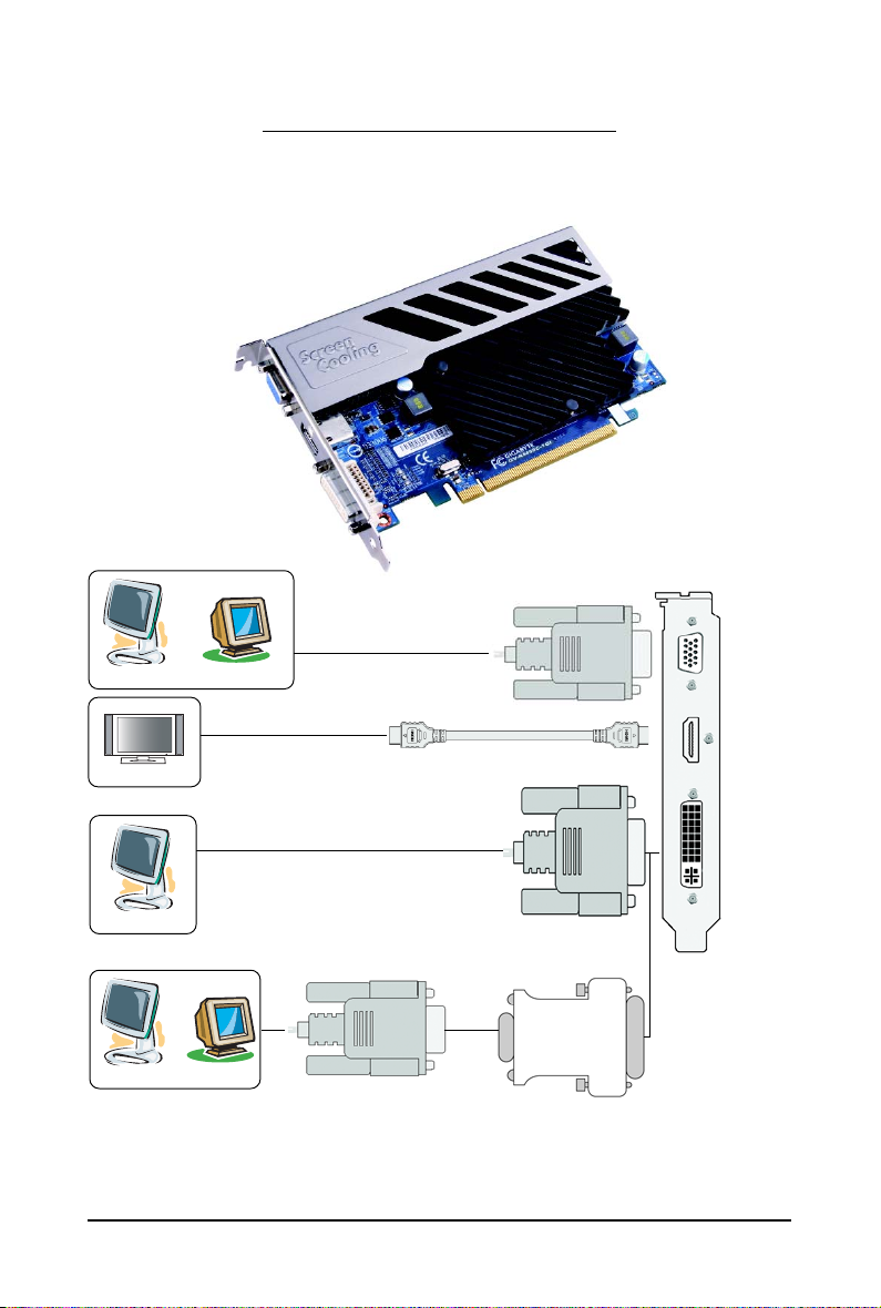
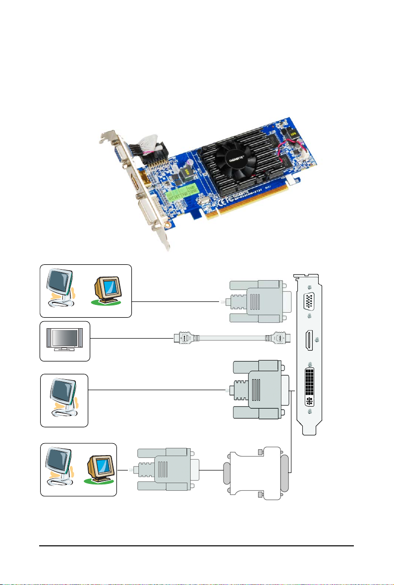
2.1. Board Layout
1. GV-R545SC-1GI
D-Sub Monitor Connector
(15-pin)
HDMI Connector
DVI-I Connector
2. Hardware Installation
or
Analog LCD Monitor Analog CRT Monitor
HDMI TV
HDMI TV
Digital LCD Monitor
or
Analog LCD Monitor Analog Monitor
DVI Output
D-Sub Output
- 6 -GV-R545 Series Graphics Accelerator
D-Sub
Output
D-Sub Monitor Connector (15-pin)
HDMI
Connector
DVI-I
Connector
DVI-I to D-Sub
Adapter
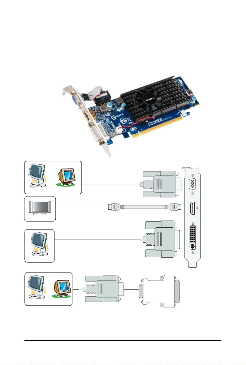
2. GV-R545OC-512I
D-Sub Monitor Connector
(15-pin)
HDMI Connector
DVI-I Connector
or
Analog LCD Monitor Analog CRT Monitor
HDMI TV
HDMI TV
Digital LCD Monitor
or
Analog LCD Monitor Analog Monitor
DVI Output
D-Sub Output
D-Sub
Output
DVI-I to D-Sub
Adapter
- 7 - Hardware Installation
D-Sub Monitor Connector (15-pin)
HDMI
Connector
DVI-I
Connector

3. GV-R545HM-1GI
D-Sub Monitor Connector
(15-pin)
HDMI Connector
DVI-I Connector
or
Analog LCD Monitor Analog CRT Monitor
HDMI TV
HDMI TV
Digital LCD Monitor
or
Analog LCD Monitor Analog Monitor
DVI Output
D-Sub Output
- 8 -GV-R545 Series Graphics Accelerator
D-Sub
Output
D-Sub Monitor
Connector
(15-pin)
HDMI
Connector
DVI-I
Connector
DVI-I to D-Sub
Adapter
4. GV-R545HM-512I
D-Sub Monitor Connector
(15-pin)
HDMI Connector
DVI-I Connector
or
Analog LCD Monitor Analog CRT Monitor
HDMI TV
HDMI TV
Digital LCD Monitor
or
Analog LCD Monitor Analog Monitor
DVI Output
D-Sub Output
D-Sub
Output
DVI-I to D-Sub
Adapter
- 9 - Hardware Installation
D-Sub Monitor
Connector
(15-pin)
HDMI
Connector
DVI-I
Connector
The entire Radeon HD 5450 series support HDMI output which can handle both audio and
video signals. However, audio output from the onboard audio controller or the external
sound card will be disabled when HDMI output is activated.
If no need for HDMI output function, set the onboard audio controller or the external sound
card to be the default Sound Playback device to obtain audio output from your system. For
more details, refer to page 12.
Expansion cards contain very delicate Integrated Circuit (IC) chips. To
protect them against damage from static electricity, you should follow some
precautions whenever you work on your computer.
1. Turn off your computer and unplug power supply.
2. Use a grounded wrist strap before handling computer components. If you do not
have one, touch both of your hands to a safely grounded object or to a metal object,
such as the power supply case.
3. Place components on a grounded antistatic pad or on the bag that came with the
components whenever the components are separated from the system.
The card contains sensitive electric components, which can be easily damaged by static
electricity, so the card should be left in its original packing until it is installed.
Unpacking and installation should be done on a grounded anti-static mat. The operator
should be wearing an anti-static wristband, grounded at the same point as the anti-static
mat.
Inspect the card carton for obvious damage. Shipping and handling may cause damage
to your card. Be sure there are no shipping and handling damages on the card before
proceeding.
DO NOT APPLY POWER TO YOUR SYSTEM IF THE GRAPHICS CARD IS
DAMAGED.
In order to ensure that your graphics card can work correctly, please use
official GIGABYTE BIOS only. Using non-official GIGABYTE BIOS might
cause problem(s) on the graphics card.
- 10 -GV-R545 Series Graphics Accelerator
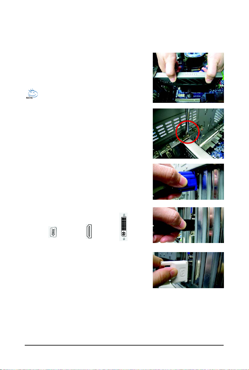
2.2. Hardware Installation
Now that you have prepared your computer, you are ready to install your graphics card.
Step 1.
Locate the PCI Express x16 slot. If necessary, remove the
metal cover from this slot; then align your graphics card with
the PCI Express x16 slot, and press it in firmly until the card is
fully seated.
Make sure that the gold edge connector of the graphics card is securely
inserted.
Step 2.
Replace the screw to fasten the card in place, and replace the
computer cover.
Step 3.
Plug the display cable into your card; then turn on the computer
and monitor. To connect a D-Sub monitor to your graphics card,
use the D-Sub connector. To connect a flat panel display to your
graphics card, use the DVI-I connector. To connect an HDMI
monitor to your graphics card, use the HDMI connector.
Connect a D-Sub monitor
To D-Sub Monitor
To HDMI Monitor
T o Flat Panel Display
Connect an HDMI monitor
Connect a flat panel display
You are now ready to proceed with the installation of the graphics card driver. Please refer to next
chapter for detailed instructions.
- 11 - Hardware Installation
 Loading...