

GIGABYTE GV-N95TD3-512H, GV-N95TOC-1GH, GV-N95TOC-512H Owner's Manual

GV -N95TD3-512H/512E
GV -N95T OC-1GH/512H
GV -N95T-512H
TM
NVIDIA® GeForce
User's Manual
Rev. 103
12MM-N95TO2H-103R
9500 GT Graphics Accelerator
Copyright
© 2008 GIGABYTE TECHNOLOGY CO., LTD
Copyright by GIGA-BYTE TECHNOLOGY CO., LTD. ("GBT"). No part of this manual may be reproduced or transmitted
in any form without the expressed, written permission of GBT.
Trademarks
Third-party brands and names are the properties of their respective owners.
Notice
Please do not remove any labels on this graphics card. Doing so may void the warranty of this card.
Due to rapid change in technology, some of the specifications might be out of date before publication of this this manual.
The author assumes no responsibility for any errors or omissions that may appear in this document nor does the author
make a commitment to update the information contained herein.
Macrovision corporation product notice:
This product incorporates copyright protection technology that is protected by U.S. patents and other intellectual property rights.
Use of this copyright protection technology must be authorized by Rovi Corporation, and is intended for home and other limited
viewing uses only unless otherwise authorized by Rovi Corporation. Reverse engineering or disassembly is prohibited.

GV-N95TD3-512H/GV-N95TD3-512E
Jun. 23, 2008
Jun. 23, 2008
GV-N95TD3-512H/
GV-N95TD3-512E
VGA Card
VGA Card

GV-N95TOC-1GH/GV-N95TOC-512H/GV-N95T-512H
Jul. 18, 2008
Jul. 18, 2008
GV-N95TOC-1GH/GV-
N95TOC-512H/
GV-N95T-512H
VGA Card
VGA Card

Table of Contents
1. Introduction ................................................................................................................ 5
1.1. Features .........................................................................................................................5
1.2. Minimum System Requirements .................................................................................... 5
2. Hardware Installation.................................................................................................. 6
2.1. Board Layout ................................................................................................................. 6
2.2. Hardware Installation......................................................................................................8
3. Software Installation.................................................................................................. 13
3.1. Windows® XP Driver and Utilities Installation ............................................................... 1 3
3.1.1. Operating System Requirements .............................................................................. 13
3.1.2. DirectX Installation........................................................................................................ 14
3.1.3. Driver Installation .........................................................................................................15
3.1.4. GIGABYTE Gamer HUD Lite on Driver CD .............................................................. 17
3.1.5. Taskbar Icon ................................................................................................................. 19
3.1.6. Display Properties Pages ........................................................................................... 20
3.1.7. nView Properties Pages
4. Troubleshooting Tips................................................................................................ 36
(Note)
....................................................................................... 31
5. Appendix ................................................................................................................. 37
5.1. How to Reflash the BIOS in MS-DOS Mode.............................................................. 37
5.2. Resolutions and Color Depth Tables (In Windows XP) ................................................. 38
Regulatory Statements ................................................................................................. 40
(Note) This item will show up when you connect two monitors.
- 4 -

1. Introduction
1.1. Features
• Powered by NVIDIA® GeForce
• Supports PCI Express 2.0
• Integrated with 512 MB GDDR3 memory (For GV-N95TD3-512H/GV -N95TD3-512E only)
• Integrated with 1 GB GDDR2 memory (For GV-N95TOC-1GH only)
• Integrated with 512 MB GDDR2 memory (For GV-N95TOC-512H/GV -N95T-512H only)
• Supports DirectX 10
®
• Supports NVIDIA
SLI
• Supports AV / S-Video / TV -Out and HDTV output
• Supports 2 DVI-I connectors
• Supports HDMI connector (by adapter)
• Supports 2 D-Sub connectors (by adapters)
• Supports HDTV output (by adapter)
• Supports HDCP (High-Bandwidth Digital Content Protection) technology
TM
9500 GT Graphics Processing Unit (GPU)
TM
(Scalable Link Interface) technology
(Note)
1.2. Minimum System Requirements
• Hardware
®
- Intel
Pentium®/CoreTM 2 or AMD AthlonTM/Phenom
- 128 MB of system memory; 2 GB or more for best performance
- Optical drive for software installation (CD-ROM or DVD-ROM drive)
- A 450 Watt power supply or above is a must
• Operating System
- Windows
- Windows
- Windows
®
Vista
®
XP with Service Pack 2 (SP2)
®
XP Professional x64 Edition
TM
TM
• SLI
Configuration
If you are planning on using this graphics card as part of an SLI system, the following
are required:
- An SLI certified motherboard with two PCI Express x16 slots and correct chipset driver
- Two GV -N95TD3-512H/GV-N95TOC-1GH/GV-N95T OC-512H
- A power supply with 550-watt or above is recommended
- An SLI bridge connector
(Note) SLI technology requires a PCI Express motherboard with two x16 physical connectors. Graphics cards working in an
SLI configuration must be with the same model name (e.g. GV-N95TD3-512H/GV-N95TOC-1GH/GV-N95TOC-512H)
and from the same vendor (e.g. GIGABYTE TECHNOLOGY).
- 5 - Introduction
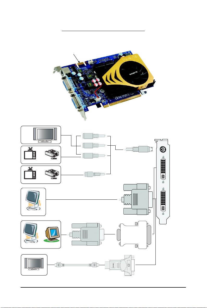
2.1. Board Layout
TV-Out
DVI-I Connector 1
DVI-I Connector 2
2. Hardware Installation
SLI Connector
HDTV
or
NTSC / PAL TV Projector
or
NTSC / PAL TV Projector
Digital LCD Monitor
or
Analog LCD Monitor Analog Monitor
HDMI TV
DVI Output
Y
Pr
Pb/AV Output
S-Video Output
D-Sub
Output
DVI-I to HDMI Adapter
DVI-I to D-Sub
Adapter
TV-Out
DVI-I
Connector 1
DVI-I
Connector 2
- 6 -GV-N95T Series Graphics Accelerator
Expansion cards contain very delicate Integrated Circuit (IC) chips. To
protect them against damage from static electricity, you should follow some
precautions whenever you work on your computer.
1. Turn off your computer and unplug power supply.
2. Use a grounded wrist strap before handling computer components. If you do not
have one, touch both of your hands to a safely grounded object or to a metal object,
such as the power supply case.
3. Place components on a grounded antistatic pad or on the bag that came with the
components whenever the components are separated from the system.
The card contains sensitive electric components, which can be easily damaged by static
electricity, so the card should be left in its original packing until it is installed.
Unpacking and installation should be done on a grounded anti-static mat. The operator
should be wearing an anti-static wristband, grounded at the same point as the anti-static
mat.
Inspect the card carton for obvious damage. Shipping and handling may cause damage
to your card. Be sure there are no shipping and handling damages on the card before
proceeding.
DO NOT APPLY POWER TO YOUR SYSTEM IF THE GRAPHICS CARD IS
DAMAGED.
In order to ensure that your graphics card can work correctly, please use
official GIGABYTE BIOS only. Using non-official GIGABYTE BIOS might
cause problem(s) on the graphics card.
- 7 - Hardware Installation
2.2. Hardware Installation
Now that you have prepared your computer, you are ready to install your graphics card.
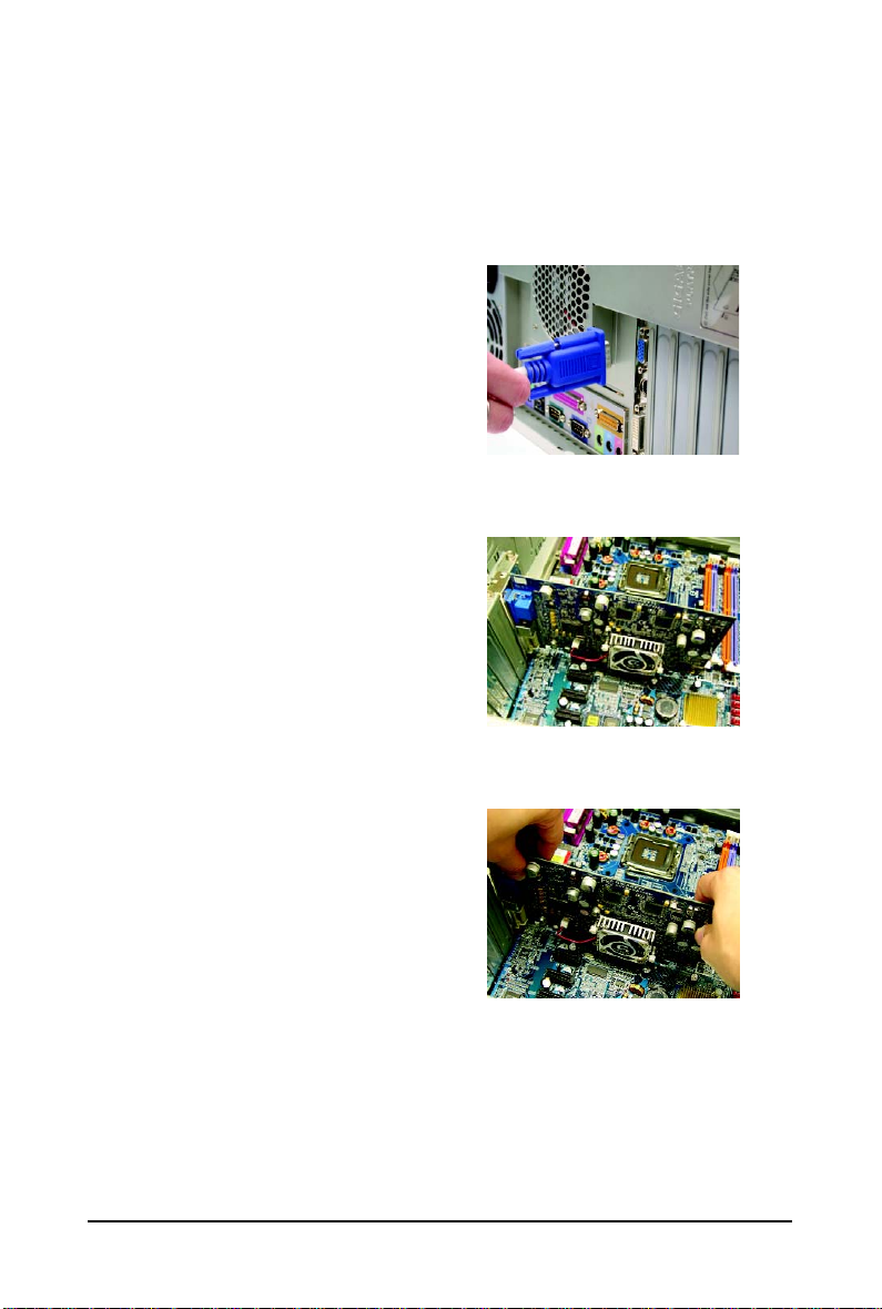
To remove the existing graphics card:
Step 1.
Power off the computer and monitor, then disconnect
the display cable from the back of your computer.
Step 2.
Remove the computer cover. If necessary, consult
your computer's manual for help in removing the
cover.
Step 3.
Remove any existing graphics card from your
computer.
- 8 -GV-N95T Series Graphics Accelerator
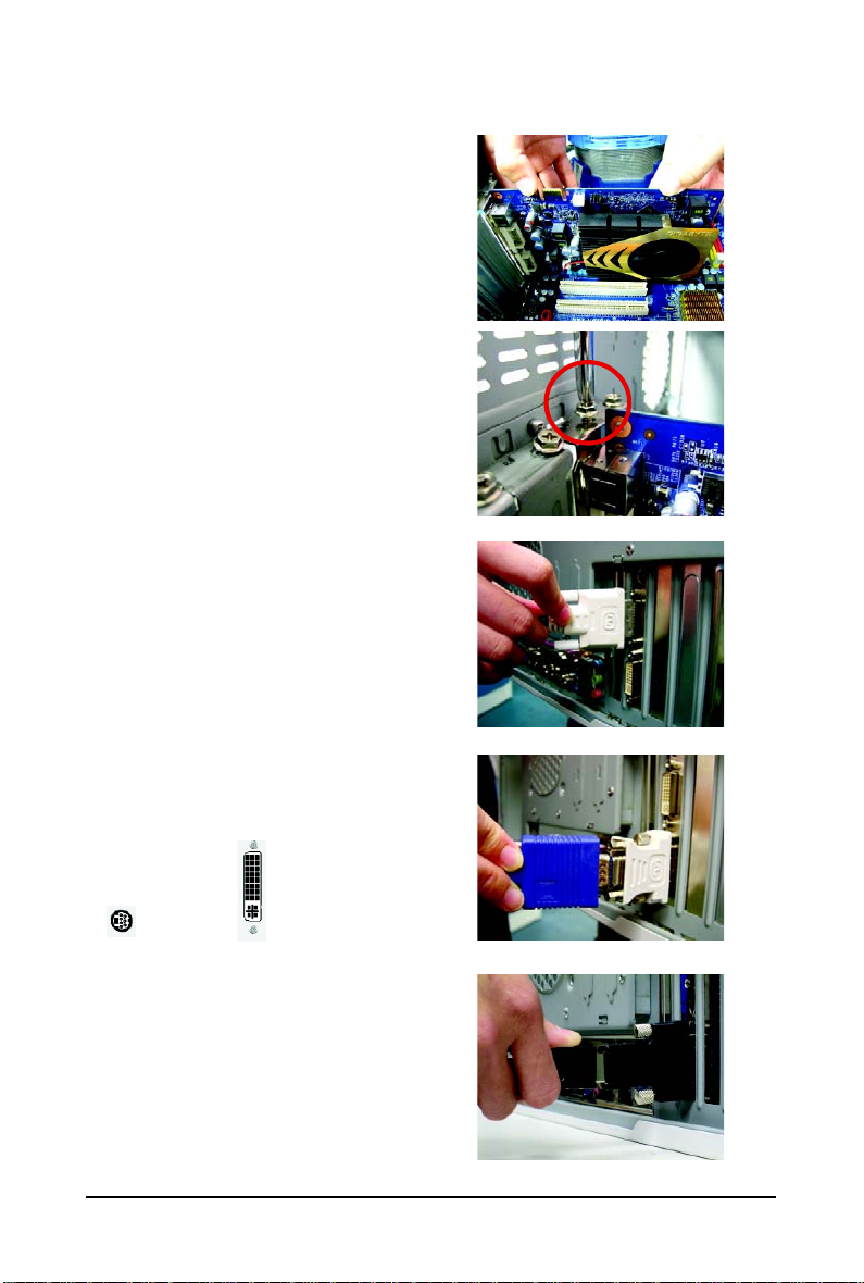
To install your new graphics card:
Step 1.
Locate the PCI Express x16 slot. If necessary, remove the metal cover from this slot; then align your
graphics card with the PCI Express x16 slot, and
press it in firmly until the card is fully seated.
* Please make sure that the gold edge connector of
the graphics card is securely inserted.
Step 2.
Replace the screw to fasten the card in place, and
replace the computer cover.
Step 3.
Plug the display cable into your graphics card; then
turn on the computer and monitor. To connect a flat
panel directly to your graphics card, use the DVI-I
connector. To connect a D-Sub monitor to the DVI-I
connector, plug the DVI-I to D-Sub adapter into the
DVI-I connector, then plug the monitor cable into the
adapter. Or use the DVI-I to HDMI adapter to connect
an HDMI monitor.
(Note: Only the DVI-I Connector 2 supports the DVI-I to
HDMI adapter.)
Connect a flat panel
T o TV / VCR T o Flat Panel Display
Connect a D-Sub monitor via DVI-I to D-Sub adapter
Connect an HDMI monitor via DVI-I to HDMI adapter
- 9 - Hardware Installation
Step 4.
To connect an HDMI TV, use either Method A or
Method B below (depending on your motherboard
design) to enable the S/PDIF in function for the graphics card. It is recommended Method A be used on
motherboards that have a free S/PDIF header.
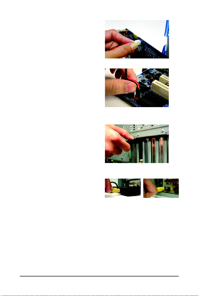
Method A (via the S/PDIF out header):
Connect the provided S/PDIF cable to the graphics
card and the S/PDIF out header on your motherboard
(the red wire connects to the S/PDIF out pin and the
black to the Ground pin).
Method B (via the coaxial S/PDIF out jack):
Connect the GIGABYTE video adapter to the TVOut port on the graphics card. Insert one end of the
SPDIF coaxial cable (optional) into the S/PDIF in
jack on the adapter and the other end into the coaxial S/PDIF out jack on your motheboard.
A-1. Connect the S/PDIF cable to the graphics card
A-2. Connect the S/PDIF cable to the motherboard.
B-1. Connect the GIGABYTE video adapter to the TVOut port on the graphics card
B-2.Connect the SPDIF coaxial cable (optional)
to the video adapter and motherboard
You are now ready to proceed with the installation of the graphics card driver. Please refer to next
chapter for detailed instructions.
- 10 -GV-N95T Series Graphics Accelerator
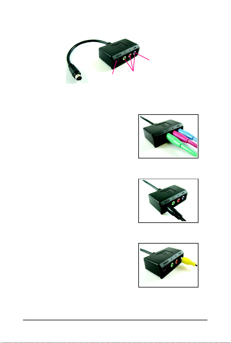
GIGABYTE Video Adapter
AV Out
S-Video Out
Connect to the TV-Out port on
the graphics card.
(1) Connecting HDTV
Connect your HDTV cables to the video adapter according to
the corresponding color.
(Y= Green, Pr= Red, Pb= Blue)
(2) Connecting S-Video
If your TV has a S-Video connection, connect the S-Video
cable from your TV to the S-Video Out port on the adapter.
HDTV Component
(Y+Pr+Pb)
(3) Connecting AV Output
If your TV has a Composite video connection, you can connect
the RCA cable from your TV to the AV Out port on the adapter.
- 11 - Hardware Installation
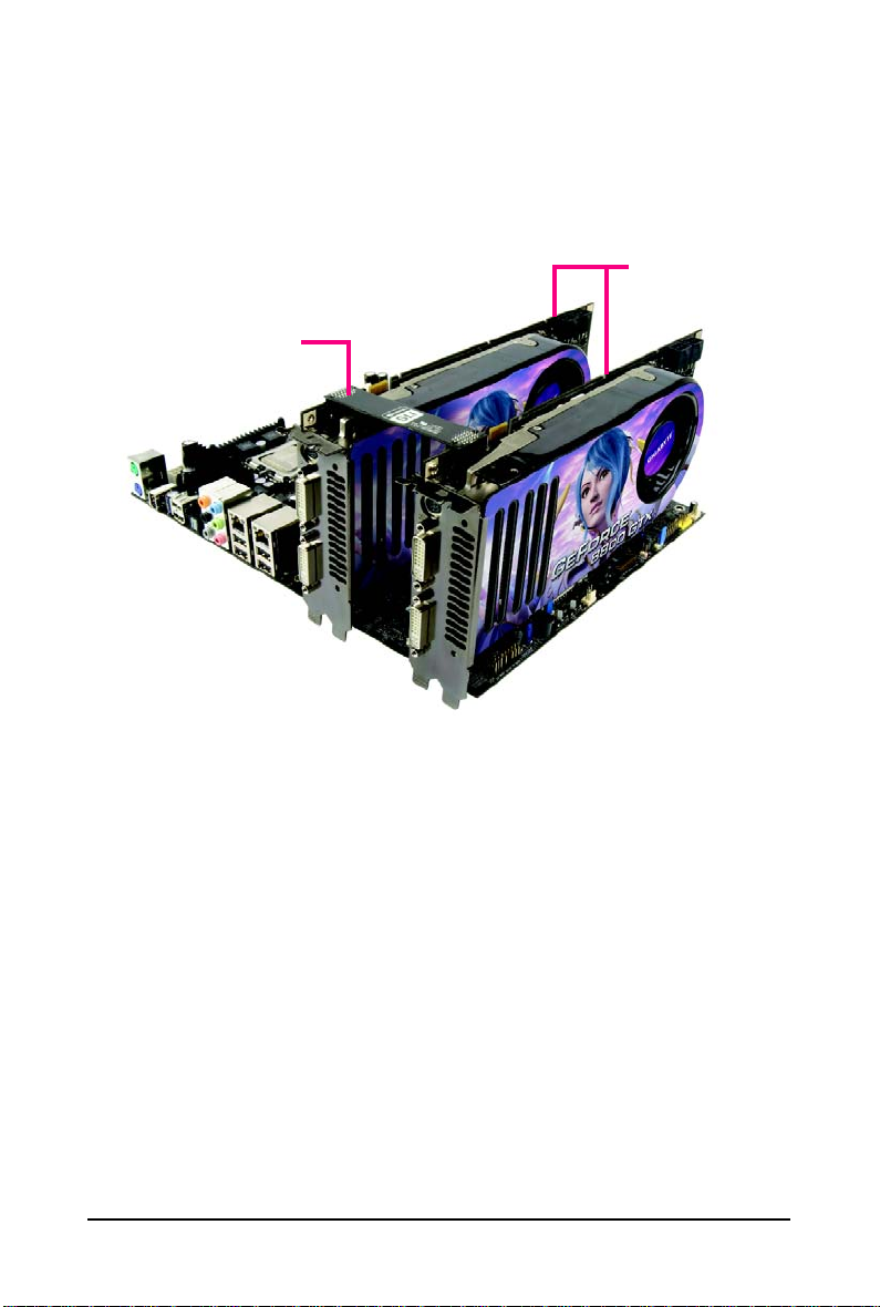
How NVIDIA® SLITM technology works:
In an SLI configuration, two SLI-ready graphics cards of the same model and the same manufacturers
are connected together via SLI bridge connector in a system that provides two x16 PCI Express slots
to scale graphics performance. The picture below shows that two graphics cards are linked in parallel
in an SLI configuration.
Two SLI-ready graphics cards of
the same type.
(Example: GV-NX88X768H-RH)
(provided by motherboard manufacturer)
SLI bridge connector
- 12 -GV-N95T Series Graphics Accelerator

3. Software Installation
In this manual, we assume that your CD-ROM drive letter to be Drive D:
The installation of drivers is very simple. When you insert the driver CD into your CD-ROM drive, you
can see the autorun window (if it does not show up, run "D:\setup.exe"). Then you can follow the
instructions to setup your graphics card driver. (Please follow the subsection "3.1.3 Driver Installation"
to install the driver for your graphics card.)
3.1. Windows® XP Driver and Utilities Installation
3.1.1. Operating System Requirements
Notice the following guidelines before installing the drivers:
1. First make sure your system has installed DirectX 9.0c or later version.
2. Make sure your system has installed the appropriate motherboard drivers (for the motherboard
drivers, please contact the motherboard manufacturer.)
- 13 - Software Installation
 Loading...