

Page 1

1
GR-ES915
iSCSI Storage Array
Quick Installation Guide
Ver: 1.0
Page 2

2
Table of Contents
SAFETY, CARE AND REGULATORY INFORMATION ............................................... 3
CHAPTER 1 PACKING LIST............................................................................................. 7
CHAPTER 2 SYSTEM OVERVIEW..................................................................................8
CHAPTER 3 SYSTEM SPECIFICATION....................................................................... 10
CHAPTER 4 OPEN FRONT BEZEL ............................................................................... 11
CHAPTER 5 RELEASE HARD DISK TRAY ................................................................. 12
CHAPTER 6 HARD DISK INSTALLATION.................................................................. 13
CHAPTER 7 OPEN TOP COVER.................................................................................... 14
CHAPTER 8 ENTER ADMINISTRATOR WEB UI....................................................... 15
Page 3

3
Safety, Care and Regulatory Information
Important safety information
Read and follow all instructions marked on the product and in the documentation before
you operate your system. Retain all safety and operating instructions for future use.
The product should be operated only from the type of power source indicated on
the rating label.
If your computer has a voltage selector switch, make sure that the switch is in the
proper position for your area. The voltage selector switch is set at the factory to the
correct voltage.
The plug-socket combination must be accessible at all times because it serves as
the main disconnecting device.
All product shipped with a three-wire electrical grounding-type plug only fits into a
grounding-type power outlet. This is a safety feature. The equipment grounding
should be in accordance with local and national electrical codes. The equipment
operates safely when it is used in accordance with its marked electrical ratings and
product usage instructions
Do not use this product near water or a heat source.
Set up the product on a stable work surface or so as to ensure stability of the
system.
Openings in the case are provided for ventilation. Do not block or cover these
openings. Make sure you provide adequate space around the system for ventilation
when you set up your work area. Never insert objects of any kind into the
ventilation openings.
To avoid electrical shock, always unplug all power cables and modem cables from
the wall outlets before removing covers.
Allow the product to cool before removing covers or touching internal components.
Precautions for Products With Laser Devices
Observe the following precautions for laser devices:
Do not open the CD-ROM drive, make adjustments, or perform procedures on a
laser device other than those specified in the product’s documentation.
Only authorized service technicians should repair laser devices.
Precautions for Products With Modems, Telecommunications, or Local
Area Network Options
Observe the following guidelines when working with options:
Do not connect or use a modem or telephone during a lightning storm. There may
be a risk of electrical shock from lightning.
To reduce the risk of fire, use only No. 26 AWG or larger telecommunications line
cord.
Do not plug a modem or telephone cable into the network interface controller (NIC)
receptacle.
Disconnect the modem cable before opening a product enclosure, touching or
installing internal components, or touching an uninsulated modem cable or jack.
Do not use a telephone line to report a gas leak while you are in the vicinity of the
leak.
Page 4

4
Federal
Communications
Commission (FCC) Statement
Note: This equipment has been tested and found to comply with the limit s for a Class B digit al
device, pursuant to Part 15 of the FCC Rules. These limits are designed to provide reasonable
protection against harmful interference when th e equipment is operat ed in a com mercial
environment. This equipment generates, uses, and can radiate radio frequency energy and, if not
installed and used in accordance with the instructi on manual, may cau se harmful interfe rence to
radio communications. Operation of this equipment in a residential area is likely to cause harmful
interference in which case the user will be required to correct the interference at his own expense.
Properly shielded and grounded cables and connectors must be used in order to meet FCC
emission limits. Neither the provider nor the manufacturer are responsible for any radio or television
interference caused by using other than recommended cables and connectors or by unauthorized
changes or modifications to this equipment. Unauthorized changes or modifications could void the
user's authority to operate the equipment.
This device complies with Part 15 of the FCC Rules. Operation is subject to the following two
conditions:
(1) this device may not cause harmful interference, and
(2) this device must accept any interference recei ved, includi ng i nt erfe rence that m ay caus e unde si red ope ration.
FCC part 68 (applicable to products fitted with USA modems)
The modem complies with Part 68 of the FCC Rules. On this equipment is a label that contains,
among other information, the FCC registration num ber and Ringer Eq uivalence Nu mber (REN) for
this equipment. You must, upon request, provide this information to your telephone company.
If your telephone equipment causes harm to the telephone network, the Telephone Company
may discontinue your service temporarily. If possible, they will notify in advance. But, if advance
notice is not practical, you will be notified as soon as possible. You will be informed of your right
to file a complaint with the FCC.
Your telephone company may make changes in its facilities, equipment, operations, or procedures
that could affect proper operation of your equipment. If they do, you will be notified in adv ance to give
you an opportunity to maintain uninterrupted telephone service.
The FCC prohibits this equipment to be connected to party lines or coin -telephon e service.
The FCC also requires the transmitter of a FAX transmission be properly identified (per FCC Rules
Part 68, Sec. 68.381 (c) (3)).
/ for Canadian users only /
Canadian Department of Communicat ions C ompli ance Statem ent
This digital apparatus does not exceed the Class B limits for radio noise emissions from digital
apparatus as set out in the radio interference regulations of Industry Canada.
Le présent appareil numérique n'émet pas de bruits radioélectriques dépassant les limites
applicables aux appareils numériques de Classe B prescrites dans le règlement sur le brouillage
radioélectrique édicté par Industrie Canada.
DOC notice (for products fitted with an Industry Canada-compliant modem)
The Canadian Department of Communications label iden tifies certified eq uipment. This ce rtification
means that the equipment meets certain telecommunications network protective, operational and
safety requirements. The Department does not guarantee the equipment will operate to the user
satisfaction.
Before installing this equipment, users ensure that it is permissible to be connected to the facilities of
the local Telecommunications Company. The equipment must also be installed using an acceptable
method of connection. The customer should be aware that compliance with the above conditions
might not prevent degradation of service in some situations.
Repairs to certified equipment should be made by an authorized Canadian maintenance facility
designated by the supplier. Any rep airs or alt erations m ade by the u ser to this equipment, or
equipment malfunctions, may give the telecommunications company cause to request the user to
disconnect the equipment.
Users should ensure for their own protection that the electrical ground connections of the power
utility, telephone lines and internal metallic water pi pe system, if resent are connect ed together. T his
precaution may be particularly important in rural areas.
Caution: Users should not attempt to make such connections themselves, but should contact the
appropriate electric inspection authority, or electrician, as appropriate.
Page 5

5
NOTICE: The Load Number (LN) assigned to each te rminal devi ce denotes the p ercentage of the
total load to be connected to a tele phone lo op which i s used by th e device, to prevent ov erloadi ng.
The termination on a loop may consist of any combination of devices subje ct only to the requireme nt
that the sum of the Load Numbers of all the devices does not exceed 100.
/ for European users only /
Page 6

6
European Community Directive Conformance Statement
This product is in conformity with the protection requirements of EC Council Low Voltage
Directive (Safety) 73/23/EEC, EMC Directive 89/336/EEC on the approximation of the laws of
the Member States relating to electro-magnetic compatibility.
R&TTE Directive (applicable to products fitted with European modems)
This modem does not require any physical and/or software additional switch settings from the
User and is suitable for use only on telephone lines provided with Multi-Frequency Dialing
facilities.
The equipment has been approved in accordance with Council Decision 99/5/EC on radio
equipment and terminal telecommunication equipment and the mutual recognition of their
conformity.
Page 7

7
Chapter 1 Packing List
GR-ES915 packing content list
1. GR-ES915 system * 1
2. Quick installation guide * 1
3. Software manual CD * 1
4. Power cord * 1
5. Rack mount kit * 2
6. Front bezel key * 2
7. Screw set * 1
Page 8
8
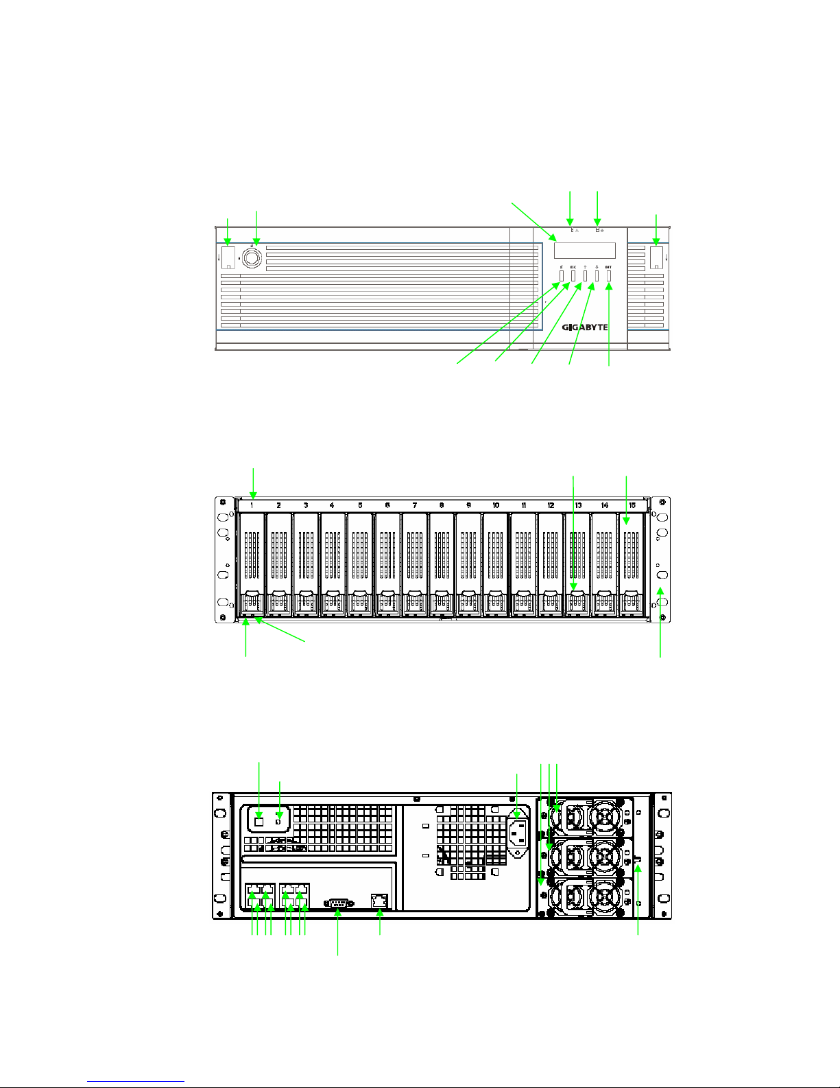
Chapter 2 System Overview
Front bezel
Front view
Rear view
Key lock
Power LED Status LED
LCD display
Release button
Release button
LCD module button: mute / ESC / up / down / ENT
Disk number 1~15
Hard disk tray Hard disk tray release button
Hard disk power LED
Hard disk access LED
Rack mounting ear
Power module 1,2,3
Power socket
System power button
System reset button
Power mute button Gigabit port 1~8
Console port
Management port
Page 9
9
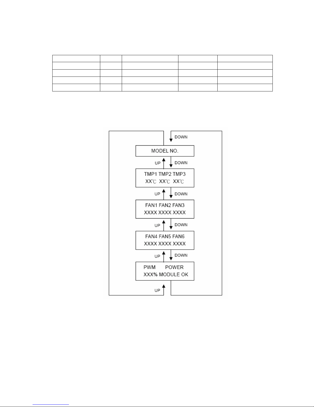
Light definition
Color On Blank Off
Power Blue System power on
X
System power off
Status Red System ready
X
System not ready
HDD power LED Blue HDD connected
X
HDD not connected
HDD access LED Green
X
HDD access HDD no access
LCD module display
Page 10

10
Chapter 3 System Specification
Model GR-ES915
iSCSI Storage Array
Controller
Processor iStor GSATX-816
Cache Memory 512MB ECC+REG DDR SDRAM Up to 4GB
Host Channel iSCSI, Gigabyte *8
Disk Channel Serial ATA-I/Serial ATA-II
RAID Level 0,1,10,5,JBOD
Backup Battery Unit Supported
Platform Support Operation System Independent
Disk Support
Number 15
Type Serial ATA-I/Serial ATA-II
RPM 7200rpm
Size 160GB, 250GB, 400GB, 500GB, 750GB
Enclosure
Hot-Swap Module Power Supply, FAN, Hard Disk
Security Front Panel with Key lock
LCD Module Display Environment Status
Physical
Power Redundant, 700W (350W, n+1)
Dimension 440(w)*131.9(h)*628.2(d), 3U
Weight (without HDD) 20kg
Installation Rack Mount Kits
Page 11
11
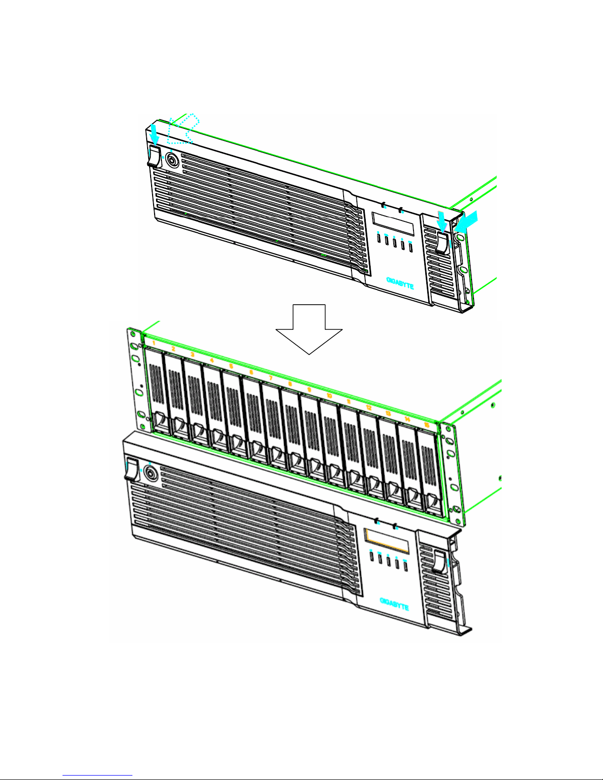
Chapter 4 Open Front Bezel
1
1
2
2
Page 12
12
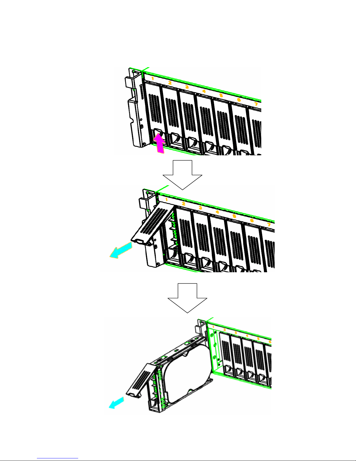
Chapter 5 Release Hard Disk Tray
Page 13
13
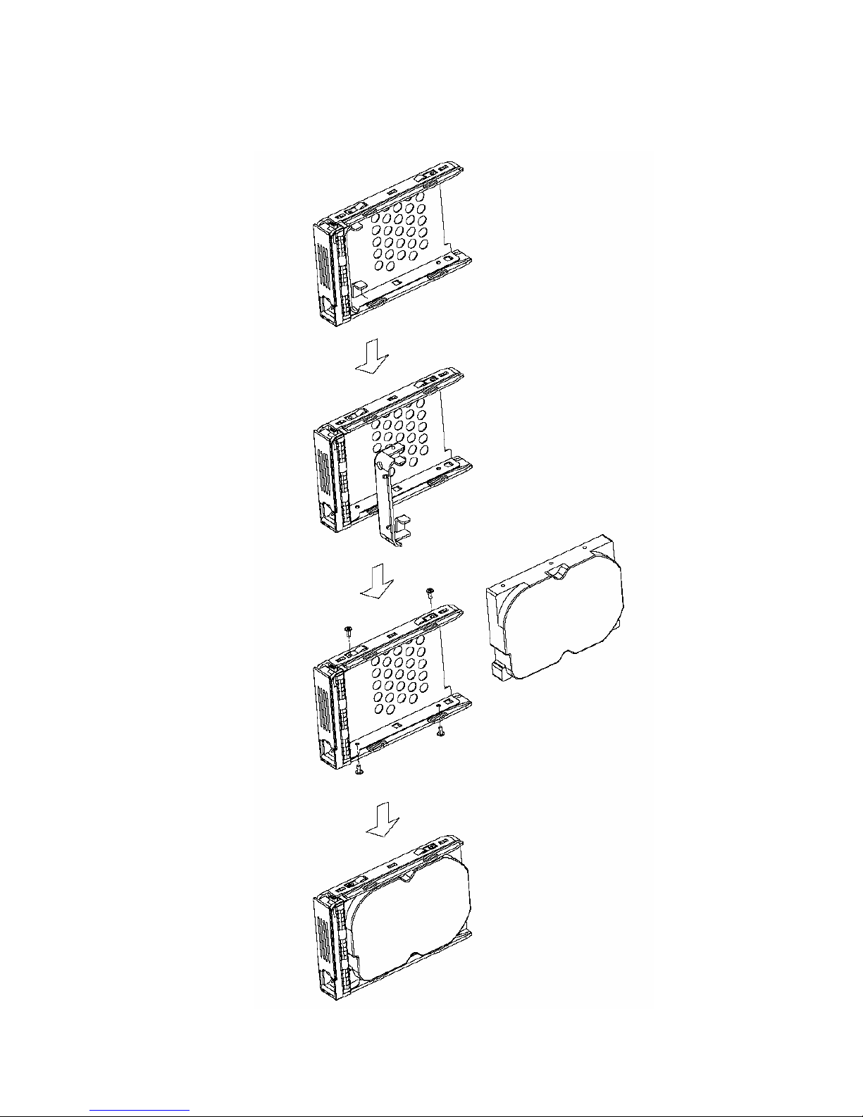
Chapter 6 Hard Disk Installation
Page 14
14
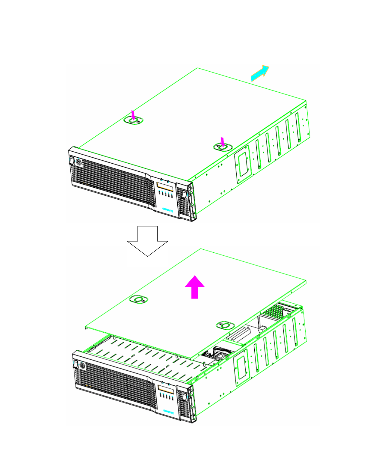
Chapter 7 Open Top Cover
1
1
2
Page 15
15
Chapter 8 Enter Administrator Web UI
1. Power-up the GigaStorATX Storage Controller.
2. Wait for a while until (3mins-5mins) GigaStorATX is getting
ready.
3. In the browser’s address bar, type the default IP address
(192.168.1.1) for the GigaStorATX management console and press
the Enter key.
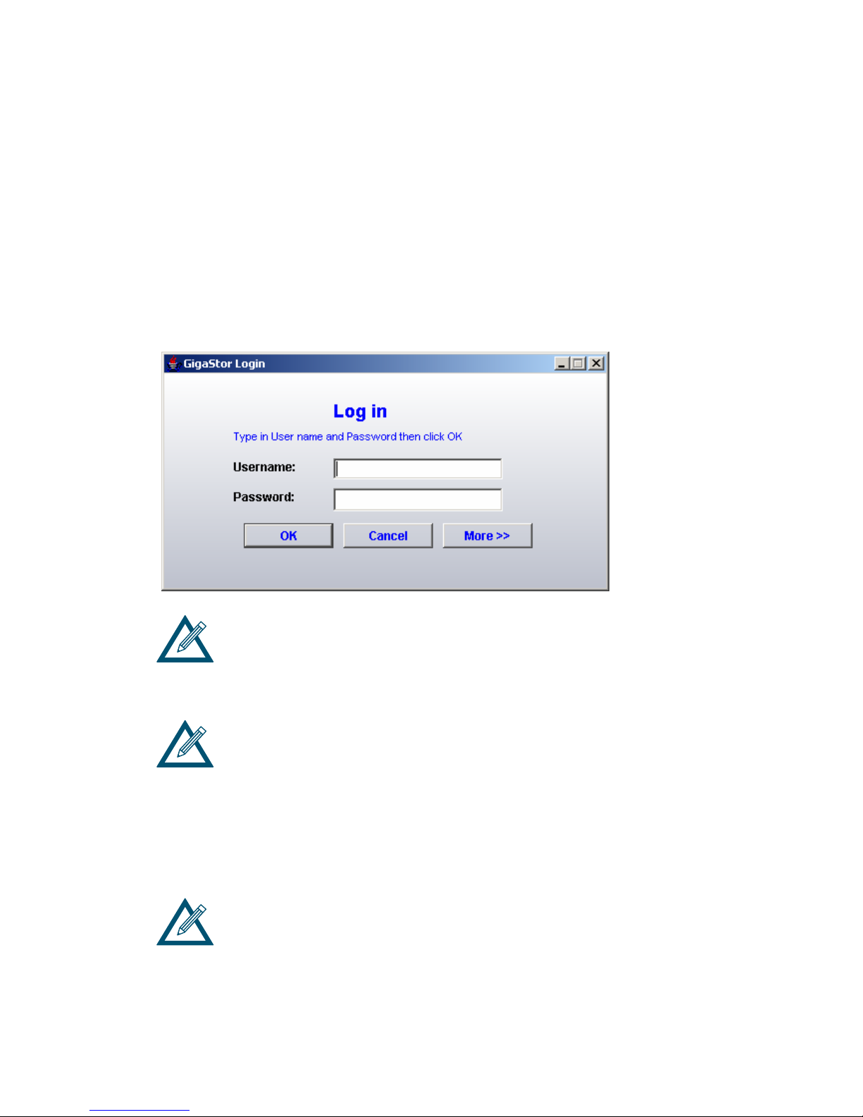
4. The GigaStorATX console management Log in screen appears.
If the GigaStorATX management console does not start automatically return
to the HTTP://192.168.1.1 browser window and click on the click here link. If
you are having problems starting the GigaStorATX Management Console you
may need to install and or reinstall Java and/or Java Web start by clicking the
lower click here link.
The IP address on your PC's NIC must be on the same IP subnetwork
(192.168.1.x) as the management port.
5. Enter your username and password in the appropriate text boxes.
The first time you log in, you must use the default username
(admin) and password (admin).
If desired, you can click the More button to view the IP address you will be
connecting to and change it if necessary.
Page 16
16
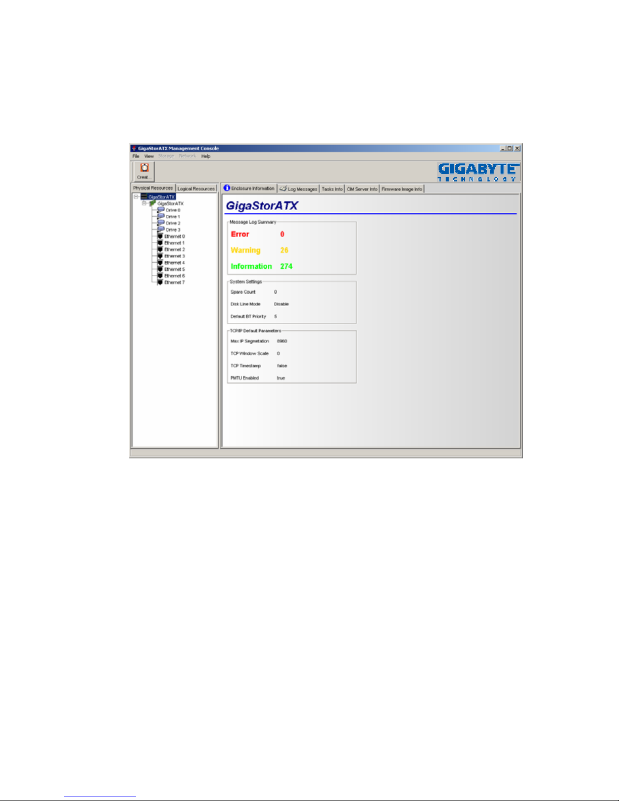
6. Click the OK button. A screen appears with a progress bar as the
connection is being made to the GigaStorATX. Once the
connection is made, the main screen appears.
Note: Please check the software manual CD for detail software
operating information.
 Loading...