

Page 1

i-RAM
(GO-RAMDISK-BOX-RH)
User's Manual
Rev. 100
24MD1-IRMBOX-02R
* The WEEE marking on the product indicates this product must not be disposed of with user's other household waste
and must be handed over to a designated collection point for the recycling of waste electrical and electronic equipment!!
* The WEEE marking applies only in European Union's member states.
Copyright
© 2006 GIGA-BYTE TECHNOLOGY CO., LTD. All rights reserved.
The trademarks mentioned in the manual are legally registered to their respective companies.
Notice
The written content provided with this product is the property of Gigabyte.
No part of this manual may be reproduced, copied, translated, or transmitted in any form or by any
means without Gigabyte's prior written permission. Specifications and features are subject to change
without prior notice.
Page 2

English
Thank you for selecting GIGABYTE's latest i-RAM product. This user's manual gives
information about i-RAM features and specifications, and will lead you through the installation of i-
RAM in your system. Read this guide and related precautions before installing i-RAM.
Table of Contents
1. Product Features ........................................................................................................ 3
2. Product Specifications ................................................................................................. 4
3. Product Requirements ................................................................................................ 4
4. Product Introduction .................................................................................................... 5
5. Precautions ................................................................................................................ 6
6. Installation Directions ................................................................................................... 7
Hardware Installation ............................................................................................................... 7
Software Setup ........................................................................................................................ 9
7. Appendix .................................................................................................................... 9
8. iRAM EasyBackup utility introduction .......................................................................... 11
- 2 -
Page 3

1. Product Features
z Fastest System Boot-Up speed
Fully SATA1.0a compliant; i-RAM can be used as a boot device.
z Fastest Solid State Disk
Dedicated DDR design, Supports DDR 266/333/400 memory modules.
z Fastest Data Access
Ideally design for applications that require massive storage data access, like Audio/Video
Capture & Edit, 3D Graphics designs, File sharing, Database exchange, Server, Workstation
and Web/Email servers etc.
z Data Protection
After PC shutdown, the stored data can be protected by using PC standby power.
When AC wall power is off or after unplug power cord; the stored data can be
using i-RAM backup battery
(Note 1)
. This is good for user/engineer to do some needful actions (e.g.
move i-RAM alone or with PC in the short distance/period and backup i-RAM data) before AC
wall power resume or re-plug in power cord.
z No additional drivers required.
z Supports Backup and Restore software utilities.
z Noiseless solution compared to traditional hard drives.
z Vibration proof compared to traditional hard drives.
protected by
English
(Note 1): Actual battery life may vary based on usage and different memory modules.
- 3 -
Page 4

English
2. Product Specifications
z Convenience to use for both PC and Server .
z SATA Interface
- SATA 1.0a Compliant
- Supports one SATA connector
- Up to 150MB/s data transfer rate
z Memory Interface
- Max amount of memory supported is 4GB
- Four 184-Pin/2.5V DDR DIMM sockets
- Supports DDR 266/333/400
(Note 2)
- Supports DIMM up to 4.2mm thickness (including heat-sink)
z Backup Battery
- One 1,700mAh lithium battery
3. Product Requirements
z One available SATA (1.5Gb/s) compliant connector
z Systems based on Intel ICH6 / ICH7 / ICH8 / C19 series, VIA 8237A / VIA8237R /
VIA 8237R+ series, SiS 964, nVIDIA MCP51 / MCP55 / MCP61 / CK804 South Bridge.
(Note 2): Please refer to the recommended memory support list on Page 9.
If the i RAM box temperature is too high(over 50oC), then it could cause the battery to over
heat prompting to battery bulging. This can also affect the battery to be unable to charge and
discharge power normally.
The data in the i-RAM will be lost when the battery has no more power.
- 4 -
Page 5
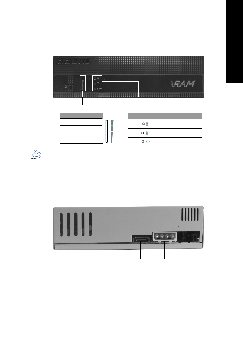
4. Product Introduction
Front Panel
Battery
Capacity
Indicator
Button
English
Battery Capacity Indicator Button
LED Light Capacity
4 section 100%
3 section 75%
2 section 50%
1 section 25%
Even in power off mode, battery indicator button can still be used for the purpose of checking
the power level. The battery can be charge only when the i-RAM is at the power off mode.
Once it is fully charged, the red LED will shut off.
Battery Status Indicator Button
LED Light Status Message
Full
Charge
R / W
Green Full
Red Charge
Yellow Data Read/Write
Rear Panel
SATA
connector
Power
connector
5V SB
connector
- 5 -
Page 6

English
5. Precautions
General Precautions:
The memory size available will be less than the total size of the installed memory.
When the system is set to RAID mode, the RAID controller might occupy some disk space as
buffer. For example, when the ICH7R RAID controller is set to RAID 0 or RAID 1, the total hard
drive capacity will be 512MB~1GB less than the actual capacity.
For users who wish to install operating system in i-RAM, please prepare the minimum free hard
disk space for the operating system.
To protect data integrity and extend battery lifespan, it is not recommended that you unplug the
AC power cord of the power supply.
Important Battery Information:
Please do not remove the battery. If the battery appears to be damaged or does not function
properly, please contact the place of purchase for further checking.
i-RAM memory sockets are powered on after the battery is charged, please handle with care to
prevent short circuit and damage.
Do not dispose of the battery in fire. To avoid injuries or causing fire hazard, please do not
disassemble or touch battery terminals with metal objects or your fingers.
If the i RAM box temperature is too high, then it could cause the battery to over heat prompting
to battery bulging. This can also affect the battery to be unable to charge and discharge power
normally.
Data Loss Preventions:
To prevent data from being lost or damaged, read the following guidelines:
Do not remove the installed memory module(s) from i-RAM.
The data in the i-RAM will be lost when the battery has no more power.
Each time before setting up the i-RAM, make sure to remove system power and the i-RAM
battery to prevent damage.
Please back up the data in i-RAM regularly using either GIGABYTE's backup tool (please
download it from GIGABYTE's website at http://www.gigabyte.com.tw) or third-party backup
utilities. Please note that data in i-RAM is not covered under the warranty.
- 6 -
Page 7
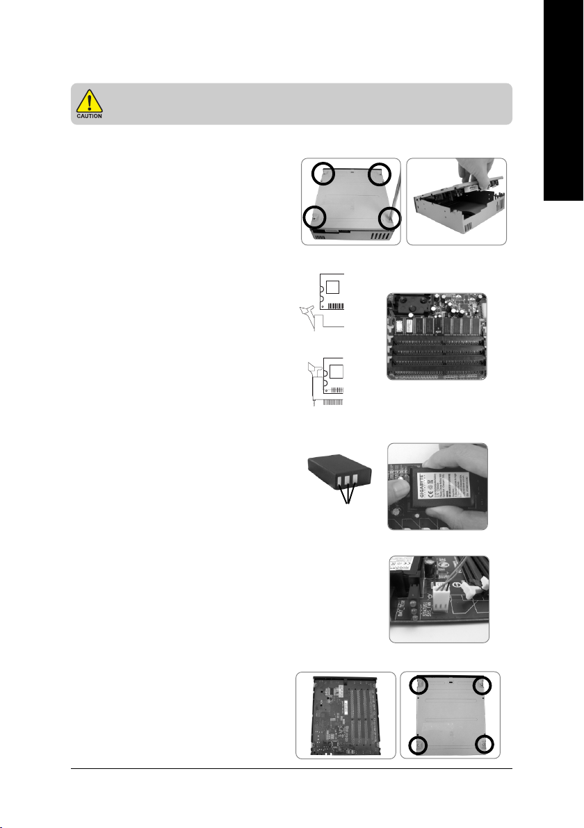
6. Installation Directions
Each time before setting up the i-RAM, make sure to remove system power and
the i-RAM battery to prevent damage.
Please read the following installation directions before using i-RAM:
Hardware Installation
8-1 : Open the cover
Please remove the four screws on the cover
(Figure a ), then pull up the cover (Figure b).
English
8- 2: Install Memory Module(s)
Place i-RAM card on an anti-static pad.
The DIMM socket has a notch, so the memory
module can only fit in one direction. Push the
clips at both end of the DIMM socket outwards
to the open position(Figure c). Insert the memory
module into the DIMM socket. Then push it
down until the retaining clips snap into place
(Figure d). We recommend slotting memory
modules from the top socket.
battery after inserting the memory module(s).
8- 3: Install Battery
Please make sure that the battery is properly
installed to the battery socket. The 3 gold pins of
the battery should be at the same direction with
the battery socket pins direction.
8- 4: Install FAN connector
Please double check the 3-pin connector to the
CPU Fan connector on the motherboard.
Replace the i-RAM
Figure c
Figure d
Anode
Figure a
Figure b
8- 5: Close the cover
First place the cover over the i-RAM card and
make sure the card and screw hole are align
then fit in the base cover. Put in the screw once
the base cover and its screw hole are well
aligned.
- 7 -
Page 8
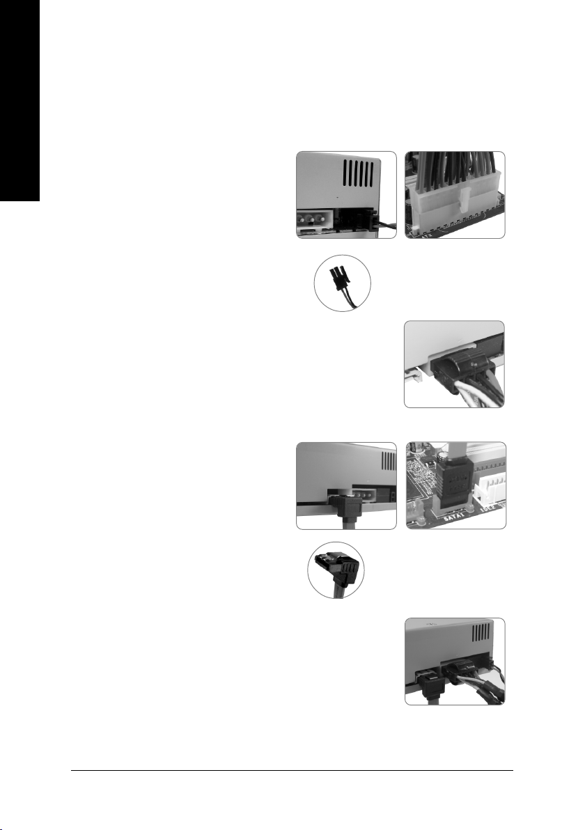
8- 6: Install i-RAM BOX into the system
Put i-RAM box into the 5.25 inch cd-rom drive.
English
8- 7: Connect the power connector of the rear
panel
8-7-1 Connect the cable of the 5V SB
Connect the cable of the 5V SB to the 5V
SB connector of the rear panel . Connect
another 24 pin power connector to the
motherboard (Figure f).
8-7-2 Connect the 4 pin power
connector to the rear panel.
8- 8: Connect the SATA cable to the rear
panel
Connect one end of the SATA connector of the
rear panel (Figure g) then connect the other end
to the motherboard SATA port.
Figure e
5V SB connector
Figure f
8- 9 : Complete
Figure g Figure h
SATA connector
- 8 -
Page 9

Software Setup
1- 1: Configure System BIOS
At system startup, enter system BIOS when prompted. Read the motherboard or system
documentation and assure that the motherboard SATA port connecting to i-RAM is enabled.
Finally, make sure i-RAM has been detected as a normal hard drive by system BIOS.
1- 2: Format i-RAM
In order for i-RAM to be visible in your operating system, it must be formatted. You can format
i-RAM using FDISK, Windows Disk Management or other third-party tools.
You are now ready to use i-RAM as a normal hard drive.
7. Appendix
Recommended Memory Support List
Please refer to the memory support list below:
DDR400 (256MB)
Module Supplier Comp. Used Module P/N. Component P/N.
Samsung Samsung KOREA 0309 PC3200U-30331-A1 K4H560838E-TCCC
M381L3223ETM-CCC 256MB (ECC)
DDR PC3200 CL3 ECC
Micron Micron MT16VDDT3264AG-40BB5 MT 46V16M8-5B
PC3200U-30330-B1 256MB DDR400 CL3
Buffalo Buffalo DD4333-S256/MC PC3200U-30330-A1 MT 46V32M8-5BC
256MB 400Mhz-CL3
HYNIX HYNIX HYMD2364A8J-D43AA HY5DU56822AT-D43
English
DDR400 (512MB)
Module Supplier Comp. Used Module P/N. Component P/N.
Transcend Mosel 512M 184 DDR=HP V58C2256804SAT5B
512M DDR400 DIMM 3-3-3
8144 Y0347
Elixir Elixir M2U51264DS8HC1G-5T 512MB ELIXIR N2DS25680CT-5T
DDR400 CL3PC3200U-30330
Geil Geil 512M DDR400ULTRA(32M8) MPEA3200C2UD2-512
ProMOS Mosel V826664K24SCIW-D3 0512PP V58C2256804SC15
Transcend PSC 512M DDR400 PSD A256D30BTP 513ASN14
DIMM 2.5-3-3 TAIWAN AN-5
SIS SIS SLX164M8-T5B DDR6408-5B 6627
For the latest memory support list information, please visit GIGABYTE's website at
http://www.gigabyte.com.tw.
- 9 -
Page 10

English
DDR400 (1GB)
Module Supplier Comp. Used Module P/N. Component P/N.
Transcend Micron 1G184PDDR=LR 1GDDR400 MT 46V64M8-5B C
DIMM 3-3-3
Kingston Samsung KVR400X64C3A/1G K4H510838C-UCCC
Apacer Samsung 77.11136.464 K4H510838B-TCCC
A-DATA ADATA MDOAD6G3141Y0B1E0H ADD9608A8A-5C H0511
Buffalo Buffalo PC3200U-30330-B1 MT46V64MB-5B
elixir elixir M2U1G64DS8HB1G-5T N2DS51280BT-5T
MDT MDT M924-400-16-P15480 MDT25D5128OS-5
NANYA NANYA NT1GD64S8HC0GY-5T NT5DS64M8CS-5T 10300CPT
SAMSUNG SAMSUNG M368L2923CUN-CCC K4H510838C-UCCC
TwinMOS Hynix M2SA016AJAHXAG0811A1 HY5DU12822AT-D43
SAMSUNG SAMSUNG M368L2923CUN-CB3 K4H510838C-UCB3
KINGSTON HYNIX KVR400X64C3A/1G HY5DU12822CTP-D43
- 10 -
Page 11

8. iRAM EasyBackup utility introduction
Installation guide :
Please click the folder “i-RAM backup utility” from provided driver CD (or download it from
GIGABYTE's website at http://www.gigabyte.com.tw)
backup utility folders, DOS and Windows version.
Windows version:
After Windows OS installation, please click the icon to install the iRAM EasyBackup.
DOS version:
Please run the file “iram”.
iRAM EasyBackup main screen :
Backup i-RAM to File :
Backup i-RAM data to hard disk.
Restore File To i-RAM :
Restore the backup data from i-RAM.
. Extract the file and it will creat two main
For DOS :For Windows :
GIGABYTE i-RAM DOS Utility Rev 1.0
No. Physical Model Name Total Sectors HD Size
0 HD2 GIGABYTE i-RAM 4193279 2047MB
1. Backup i-RAM to File
2. Restore i-RAM from File
3. Exit
Please select 1-3:
English
iRAM EasyBackup screen :
Save as (destination)
select i-RAM disk
(source)
GIGABYTE i-RAM DOS Utility Rev 1.0
No. Physical ModelName Total Sectors HD Size
0 HD2 GIGABYTE i-RAM 4193279 2047MB
1. Backup i-RAM to File
2. Restore i-RAM from File
3. Exit
Please input file name (*.img):
Please keyin disk drive and path, and file
name must be¡§ *.img ¡¨.
- 11 -
Page 12

English
- 12 -
Page 13
i-RAM
(GO-RAMDISK-BOX-RH)
Rev. 100
* WEEE logo
* WEEE
© 2006 GIGA-BYTE TECHNOLOGY CO., LTD. All rights reserved.
Page 14

i-RAM i-RAM
i-RAM
.......................................................................................................... 3
.......................................................................................................... 4
.......................................................................................................... 4
.......................................................................................................... 5
.......................................................................................................... 6
.......................................................................................................... 7
.............................................................................................................................. 7
.............................................................................................................................. 9
............................................................................................ 9
i-RAM ....................................................................................11
- 2 -
Page 15

zz
z
zz
SATA 1.0a i-RAM
zz
z
zz
DDR DDR 266/333/400
zz
z
zz
zz
z
zz
i-RAM
zz
z SATA 1.0a
zz
zz
z
zz
zz
z
zz
3D/2D
i-RAM (Standby Power)
i-RAM
( 1)
i-RAM
i-RAM
SATA 1.0a
/
zz
z
zz
1
- 3 -
Page 16

zz
z
zz
zz
z SATA
zz
zz
z
zz
zz
z
zz
1,700mAh
SATA 1.0a
SATA
184-Pin/2.5V DDR
DDR 266/333/400
4.2mm ( )
150MB
4GB
( 2)
z SATA (1.5Gb/s) SATA
z Intel ICH6 / ICH7/ ICH8/ C19 VIA 8237A/ VIA 8237R/ VIA 8237R+
SiS 964 nVIDIA MCP51/ MCP55 / MCP61 / CK804
2
9
i-RAM ( 50OC)
i-RAM i-RAM
- 4 -
Page 17

LED
4 100%
3
2
1
75%
50%
25%
LED
Full
Charge
R / W
- 5 -
SATA
5V SB
Page 18

buffer ICH7R RAID 0 RAID 1
512MB~ 1GB
i-RAM
i-RAM
i-RAM
i-RAM
i-RAM :
i-RAM
i-RAM i-RAM
i-RAM (
http://www.gigabyte.com.tw )
i-RAM
- 6 -
Page 19

8-1
i-RAM
4 ( a)
( b)
8-2
8-3
8-4
i-RAM
( c)
( d)
a b
c
d
8-5
- 7 -
Page 20

8-6 i-RAM BOX
i-RAM BOX 5.25
8-7
8-7-1 5V Stand By
5V Stand By
i-RAM 5V SB
( e)
24-pin
e
f
( f)
8-7-2 4-pin
8-8 SATA
SATA
i-RAM SATA ( g)
( h)
8-9
SATA
5V SB
g
SATA
h
- 8 -
Page 21

1-1 BIOS
BIOS /
i-RAM SATA i-RAM
BIOS
1-2 i-RAM
i-RAM i-RAM
FDISK Windows i-RAM
i-RAM i-RAM
:
DDR400 (256MB)
Module Supplier Comp. Used Module P/N. Component P/N.
Samsung Samsung KOREA 0309 PC3200U-30331-A1 K4H560838E-TCCC
M381L3223ETM-CCC 256MB (ECC)
DDR PC3200 CL3 ECC
Micron Micron MT16VDDT3264AG-40BB5 MT 46V16M8-5B
PC3200U-30330-B1 256MB DDR400 CL3
Buffalo Buffalo DD4333-S256/MC PC3200U-30330-A1 MT 46V32M8-5BC
256MB 400Mhz-CL3
HYNIX HYNIX HYMD2364A8J-D43AA HY5DU56822AT-D43
DDR400 (512MB)
Module Supplier Comp. Used Module P/N. Component P/N.
Transcend Mosel 512M 184 DDR=HP V58C2256804SAT5B
512M DDR400 DIMM 3-3-3
8144 Y0347
Elixir Elixir M2U51264DS8HC1G-5T 512MB ELIXIR N2DS25680CT-5T
DDR400 CL3PC3200U-30330
Geil Geil 512M DDR400ULTRA(32M8) MPEA3200C2UD2-512
ProMOS Mosel V826664K24SCIW-D3 0512PP V58C2256804SC15
Transcend PSC 512M DDR400 PSD A256D30BTP 513ASN14
DIMM 2.5-3-3 TAIWAN AN-5
SIS SIS SLX164M8-T5B DDR6408-5B 6627
(http://www.gigabyte.com.tw)
- 9 -
Page 22

DDR400 (1GB)
Module Supplier Comp. Used Module P/N. Component P/N.
Transcend Micron 1G184PDDR=LR 1GDDR400 MT 46V64M8-5B C
DIMM 3-3-3
Kingston Samsung KVR400X64C3A/1G K4H510838C-UCCC
Apacer Samsung 77.11136.464 K4H510838B-TCCC
A-DATA ADATA MDOAD6G3141Y0B1E0H ADD9608A8A-5C H0511
Buffalo Buffalo PC3200U-30330-B1 MT46V64MB-5B
elixir elixir M2U1G64DS8HB1G-5T N2DS51280BT-5T
MDT MDT M924-400-16-P15480 MDT25D5128OS-5
NANYA NANYA NT1GD64S8HC0GY-5T NT5DS64M8CS-5T 10300CPT
SAMSUNG SAMSUNG M368L2923CUN-CCC K4H510838C-UCCC
TwinMOS Hynix M2SA016AJAHXAG0811A1 HY5DU12822AT-D43
SAMSUNG SAMSUNG M368L2923CUN-CB3 K4H510838C-UCB3
KINGSTON HYNIX KVR400X64C3A/1G HY5DU12822CTP-D43
(http://www.gigabyte.com.tw)
- 10 -
Page 23

i-RAM
i-RAM backup utility
DOS Windows DOS Windows
Wondows
iRAM EasyBackup
DOS
iram
iRAM EasyBackup
For DOS :For Windows :
Backup i-RAM to File
iRAM
Restore File To i-RAM
i-RAM
iRAM EasyBackup
i-RAM
*.img
- 11 -
Page 24

- 12 -
 Loading...