

Page 1
54 Mbps Wireless VPN Router
GN-BR404W
User’s Guide
Rev.1.0b Second Edition
Page 2

Safety, Care and Regulatory Information
Important safety instructions
Read and follow all instructions marked on the product and in the documentation before
you operate your system. Retain all safety and operating instructions for future use.
The product should be operated only from the type of power source indicated on the
rating label.
The plug-socket combination must be accessible at all times because it serves as the
main disconnecting device.
All products hipped with a three-wire electrical grounding-type plug only fits into a
grounding-type power outlet. This is a safety feature. The equipment grounding should
be in accordance with local and national electrical codes. The equipment operates
safely when it is used in accordance with its marked electrical ratings and product
usage instructions
Do not use this product near water or a heat source.
Set up the product on a stable work surface or so as to ensure stability of the system.
Openings in the case are provided for ventilation. Do not block or cover these openings.
Make sure you provide adequate space around the system for ventilation when you set
up your work area. Never insert objects of any kind into the ventilation openings.
To avoid electrical shock, always unplug all power cables and modem cables from the
wall outlets before removing covers.
Allow the product to cool before removing covers or touching internal components.
Use only the power cord and batteries indicated in this manual. Do not dispose of
batteries in a fire. They may explode. Check with codes for possible special
disposal instructions.
Precautions for Products With Modems, Telecommunications, or Local Area Network
Options
Observe the following guidelines when working with options:
• Avoid using a telephone (other than a cordless type) during an electrical storm.
There may be a remote risk of electric shock from lightning.
• CAUTION - To reduce the risk of fire, use only No. 26 AWG or larger
telecommunication line cord.
• Do not plug a modem or telephone cable into the network interface controller (NIC)
receptacle.
• Disconnect the modem cable before opening a product enclosure, touching or
installing internal components, or touching an uninsulated modem cable or jack.
• Do not use a telephone line to report a gas leak while you are in the vicinity of the
leak.
• Do not use this product near water, for example, near a bathtub, washbowl, and
Page 3

kitchen sink or laundry tub, in a wet basement or near a swimming pool.
Federal Communications Commission (FCC) Statement
Note: This equipment has been tested and found to comply with the limits for a Class B
digital device, pursuant to Part 15 of the FCC Rules. These limits are designed to provide
reasonable protection against harmful interference when the equipment is operated in a
commercial environment. This equipment generates, uses, and can radiate radio frequency
energy and, if not installed and used in accordance with the instruction manual, may cause
harmful interference to radio communications. Operation of this equipment in a residential
area is likely to cause harmful interference in which case the user will be required to correct
the interference at his own expense.
Properly shielded and grounded cables and connectors must be used in order to meet FCC
emission limits. Neither the provider nor the manufacturer are responsible for any radio or
television interference caused by using other than recommended cables and connectors or
by unauthorized changes or modifications to this equipment. Unauthorized changes or
modifications could void the user's authority to operate the equipment.
This device complies with Part 15 of the FCC Rules. Operation is subject to the following
two conditions:
(1) This device may not cause harmful interference, and
(2) This device must accept any interference received, including interference that may
cause undesired operation.
The antenna(s) used for this transmitter must not be co-located or operating in conjunction
with any other antenna or transmitter
/ For European users only /
European Community Directive Conformance Statement
This product is in conformity with the protection requirements of EC Council Low Voltage
Directive (Safety) 73/23/EEC, EMC Directive 89/336/EEC on the approximation of the laws
of the Member States relating to electro-magnetic compatibility.
FCC Radiation Exposure Statement
This equipment complies with FCC radiation exposure limits set forth for an uncontrolled
environment. In order to avoid the possibility of exceeding the FCC radio frequency
exposure limits, human proximity to the antenna shall not be less than 20cm (8 inches)
during normal operation. Proposed RF exposure safety information to include in User’s
Manual.
Page 4

Contents
1. INTRODUCTION..................................................................................................................1
1-1. CONTENTS OF YOUR SHIPMENT .................................................................................................1
1-2. PHYSICAL INTERFACE ................................................................................................................2
1-3. LED INDICATORS.......................................................................................................................2
1-4. KEY FEATURES...........................................................................................................................3
1-5. SPECIFICATION ...........................................................................................................................4
2. SYSTEM CONNECTION & INSTALLATION .................................................................6
2-1. ADSL/CABLE MODEM REQUIREMENTS.....................................................................................6
2-2. PC HARDWARE REQUIREMENT A T THE PC END .........................................................................6
2-3. CONNECTION FOR ETHERNET USER ...........................................................................................6
2-4. CONNECTION FOR PCMCIA WIRELESS ADAPTER USER ............................................................6
3. CONFIGURATION.......................................................................................................................7
3-1. PREPARATION.............................................................................................................................7
3-2. SETUP AT YOUR PC END ............................................................................................................7
3-2-1. The Settings Under Windows2000.............................................................................8
3-2-2. Setup Under the Windows 95/98/Me........................................................................15
3-2-3. Setup Under Windows XP..........................................................................................21
3-3. SETUP FOR BROADBAND ROUTER............................................................................................28
3-4. ADVANCED SETUP....................................................................................................................48
3-4-1. Network Configuration ................................................................................................48
3-4-2. Wireless Configuration................................................................................................58
3-4-3. Routing Table................................................................................................................65
3-4-4. Virtual Server................................................................................................................67
3-4-5. Firewall Rule.................................................................................................................70
3-4-6. DNS Configuration.......................................................................................................74
3-4-7 URL Blocking Configuration........................................................................................75
3-4-8 VPN Configuration........................................................................................................76
3-5. MANAGEMENT TOOL ...............................................................................................................79
3-5-1. PPP Monitor..................................................................................................................79
3-5-2. Reboot...........................................................................................................................80
3-5-3. Initilization .....................................................................................................................81
3-5-4. Change Password .......................................................................................................82
3-5-5. Change WAN MAC......................................................................................................83
3-5-6. Upgrade Firmware.......................................................................................................84
Page 5

3-5-7. BackUp Restore...........................................................................................................85
3-5-8. Log Information............................................................................................................86
3-5-9. Save Maintenance.......................................................................................................87
3-5-10. Ping..............................................................................................................................88
3-5-11 Help ............................................................................................................................89
3-5-12 About.............................................................................................................................89
3-6. STATUS.....................................................................................................................................90
3-7. LOGOUT...................................................................................................................................95
4. TROUBLESHOOTING ...........................................................................................................96
APPENDIX A: GLOSSARY...........................................................................................................98
APPENDIX B: GENERAL PUBLIC LICENCE..........................................................................98
Page 6

1. Introduction
Thank you for using Gigabyte GN-BR404W Wireless-G Broadband Router with VPN. This
product comes with high-performance transmission rate and compatible wireless
connectivity for either your home or business and will allow you to access the data
whenever you want. You will be able to enjoy the freedom that wireless networking delivers.
The IEEE 802.11g standard is designed as a higher-bandwidth - 54M bit/sec - successor to
the popular 802.11b, or Wi-Fi standard, which tops out at 11M bit/sec. An 802.11g router
will support 802.11b and 802.11g clients.
The GN-BR404W Wireless-G Broadband Router lets you connect IEEE 802.11g or
IEEE802.11b devices to the network. With its high-speed data transmissions of up to 54
Mbps, you complete a lot of work in a short amount of time. Network users can share a
broadband Internet connection, access e-mail, download large files, videoconference, and
distribute and play digital images, videos, and MP3 files. And with up to 152-bit WEP
encryption, you can feel relieved that your wireless network communications are private.
It also provides firewall and Virtual Private Networking(VPN) features to protect your local
area network when connecting to the Internet. Additionally, GN-BR404W enables you to
easily setup all procedures in no time before using this product.
1-1. Contents of Your Shipment
Before the installation procedures, please ensure the components are not damaged during
the shipping. The shipment of the GN-BR404W includes:
- One GN-BR404W Wireless-G Broadband Router
- One AC Power Adapter (5V/2A)
- One User Guide
- Two RJ45 cable (one normal;one crossover)
- An embedded GN-WMAG 802.11b/g wireless LAN card
- One Cradle and Wall Mounting kit
Please contact your local distributor or authorized reseller immediately for any missing or
damaged components. If you require returning the damaged product, you must pack it in
the original packing material or the warranty will be voided.
1
Page 7
1-2. Physical Interface
Four Ethernet LAN Port
RJ-45, Auto-sensing and Auto-MDI/MDIX for 10/100M Ethernet LAN connection
One Ethernet WAN Port
RJ-45, Auto-sensing for 10/100M Ethernet WAN connection
Init Bottom
Initial reset (Init to factory default)
Power
The power port is where you connect the power adapter.
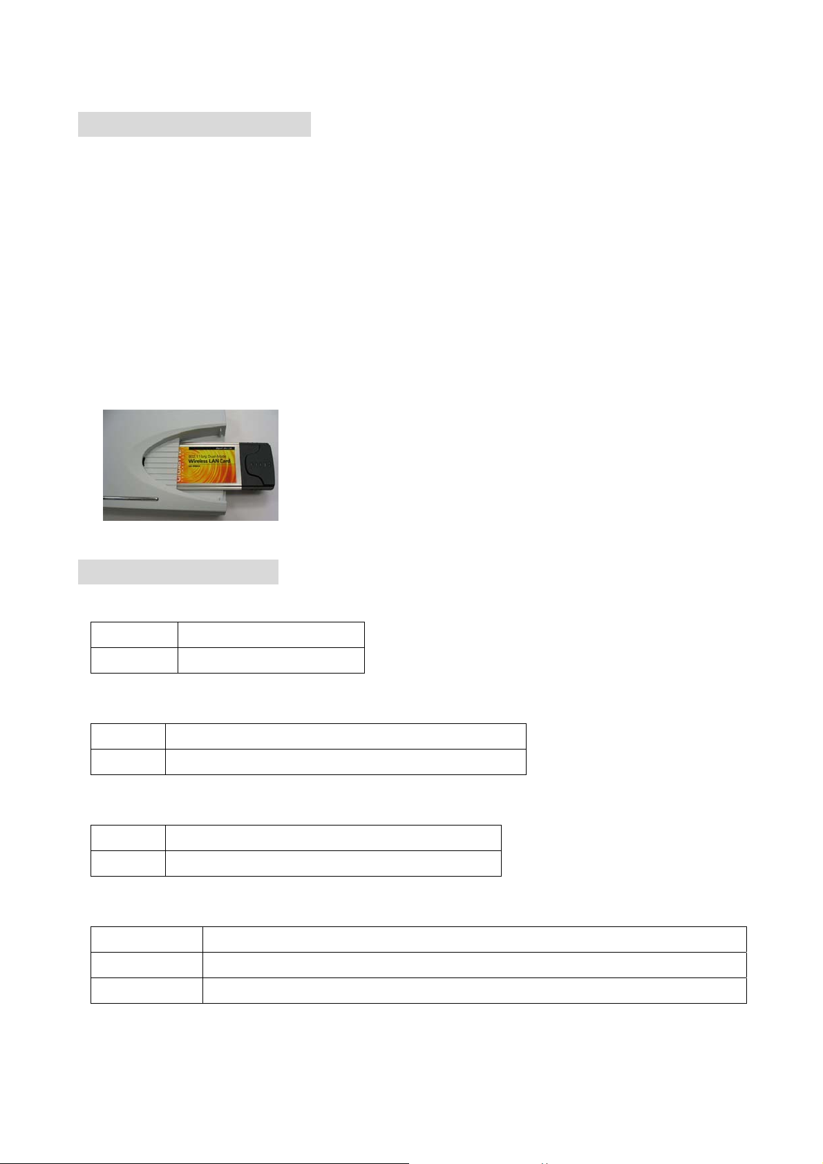
External PCMCIA Card Slot
Support the Gigabyte GN-WMAG and the GN-WLMA101 Wireless PCMCIA Card.
1-3. LED Indicators
Status
Green light Power on
Red light The device is damaged.
WAN (Green light)
On ADSL/Cable Modem is connected to WAN port.
Blinking Transmit or receive data via the WAN port.
LAN1-LAN4 (Green Light)
On 10/100 Mbps Network Connection
Blinking 10/100 Mbps Data Transmission Rate
Wireless (Green Light)
On The PCMCIA Card is plugged in.
Blinking Package transmit
Off The green light off means No PCMCIA Card installed.
2
Page 8

1-4. Key Features
Two option of plug in wireless card
Gigabyte GN-WMAG Wireless LAN Card
Gigabyte GN-WLMA101 Wireless LAN Card
Very High WAN-LAN FTP throughput up to 89.5 Mbps
Support UPnP and Windows Messenger
Advanced Smart Setup Support
Smart Installation – Automatically detects and connects to your ISP
Smart Detection – Automatically detects and changes LAN side IP when
LAN-WAN IP conflicts
Smart Wizard – Easy set up with interactive install tutorial
Advanced Network Management support
Dynamic IP, Static IP, PPPoE, PPPoE Unnumbered
PPPoE Multi Session
DHCP server with static and dynamic style
Advanced Wireless Security support
Wi-Fi Protected Access (WPA)
802.1x Secure Wireless Access
64/128/152-bit WEP encryption
Access Control List (ACL)
Advanced Firewall and Parental Control support
Stateful Packet Inspection (SPI)
Denied of Service (DoS) Protection
URL Access Filtering
Virtual Server, St ealth Mode, Exposed Host (DMZ)
Advanced Log Management support
Firewall/UPnP/WAN Connection Log
Advanced Web Management support
WAN side Remote Management
Web based Firmware upgrade
Backup and Restore System Setting
Extended Distributed Wireless Systems (EDWS) support
Wireless Distribution System (WDS) support (Point to Multi-Point and
Point to Point)
Simultaneous operation of AP and WDS functions
Virtual Private Network (VPN) Support
IPSec, L2TP, PPTP NAT traversal (VPN pass-through)
3
Page 9

IPSec support remote access VPN (client-to-site), site-to-site VPN
DNS Relay and Dynamic DNS support
Static & Dynamic Routing (RIPv1, RIPv2) support
1-5. Specification
System
Standards IEEE 802.3 (10BaseT), IEEE 802.3u (100BaseTX), IEEE 802.11b/g (Wireless)
Operating Range Wireless - Open space: 100 – 300m; Indoor: 30 - 100m
RF – 802.11b
Frequency Band 2412 ~ 24835 MHz (subject to local regulation)
Modulation Technology DSSS (Direct Sequence Spread Spectrum)
Modulation Techniques DBPSK, DQPSK, CCK
Data Rates 11, 5.5, 2, 1 Mbps, auto fallback
Output power 18 dBm @ Nominal Temp Range
Receive Sensitivity -85 dBm @ 11 Mbps date rate at nominal temperature
Antenna 1 internal antenna support diversity
RF – 802.11g (backward compatible to 802.11b)
Frequency Band 2412 ~ 24835 MHz (subject to local regulation)
Modulation Technology OFDM and DSSS
Modulation Techniques 64QAM, 16QAM, QPSK, BPSK, DBPSK, DQPSK, CCK
Data Rates 54, 48, 36, 18, 12, 11, 9, 6, 5.5, 2, 1 Mbps, auto fallback
Output power 18 dBm @ Nominal Temp Range
Receive Sensitivity -68 dBm @ 54 Mbps date rate at nominal temperature
Antenna 1 internal antenna support diversity
Regulatory and Environmental Compliance
EMC certification
Temperature Range Operating: 0 ~ 40 degree C, Storage: -20 ~ 65 degree C
Humidity 10% ~ 85% Non-condensing
FCC part 15 (USA)
CE (Europe)
Mechanical
LED indicator Power/Status LED
Wireless LED
LAN Port LED x 4
WAN Port LED x 1
Power Supply 5V DC 2A
4
Page 10

Gross Weight
320g ±5g
Dimension 178 mm * 132 mm * 43 mm
5
Page 11

2. System Connection & Installation
The following lists the requirements for the hardware installation.
2-1. ADSL/Cable Modem Requirements
It needs to have ADSL/Cable Modem with RJ-45 connectors.
2-2. PC Hardware Requirement at the PC End
It needs a PC with Ethernet card connection or a PCMCIA wireless adapter.
2-3. Connection for Ethernet User
Step 1. Please prepare an Ethernet cable (RJ- 45) first.
Step 2. Connect the Ethernet cable to the WAN port of the GN-BR404W.
Step 3. Connect an end of the network cable to the ADSL/Cable Modem of the Ethernet
connection port.
Step 4. Connect any port of the area network LAN1, 2, 3, & 4 of the GN-BR404W to your
PC.
Step 5. Connect the adapter to the power connection slot of the GN-BR404W.
Step 6. Insert the adapter to the power socket.
Step 7. The connection procedure is completed.
2-4. Connection for PCMCIA W ireless Adapter User
Please repeat Steps 1~3 of Section 2-3.
If you use wireless connection, please refer to the wireless card manual which provided by
your wireless card manufature. After installing and setting the PCMCIA Wireless Adapte r,
refer to PC configuration section in Chapter 3, follow the instruction step by step to finish
the TCP/IP Protocol setting (Setting PC) .
The SSID of the PCMCIA Wireless Adapter should be the same as the SSID of
GN-BR404W. The default value is “gigabyte” (or “any”, if your Wireless LAN Card can
support.),
please do notice the form of the SSID value whether is capital or not.
6
Page 12

3. Configuration
3-1. Preparation
Generally speaking, using the GN-BR404W for Internet connection needs the ADSL or
Cable service. We assume that you have already obtained the ADSL/Cable service from
the local telephone company or the ISP Company, and get the related connection data
ready.
Such data include:
a. IP address provided by ISP
b. Subnet mask
c. Default gateway IP address
d. Domain Name System (DNS) Server IP address
- The ISP Company provides the above data.
3-2. Setup at Your PC End
An easy-to-use web page setup interface is designed on the GN-BR404W, and the user
can perform the setup by the browser. The Gigabyte GN-BR404W Broadband Router
presets the IP address as “192.168.1.254”, and preset as a DHCP server Please follow the
step below to perform the setup under the TCP/IP network environment. Please confirm
the TCP/IP communication protocol is installed in your computer (Windows 95/98/Me/NT).
If you have not installed the TCP/IP communication protocol, please install it now, and then
select your operating system for the setup.
For Windows 2000, please jump to 3-2-1.
For Windows 95/98/Me, please jump to 3-2-2.
For Windows XP, please jump to 3-2-3
7
Page 13
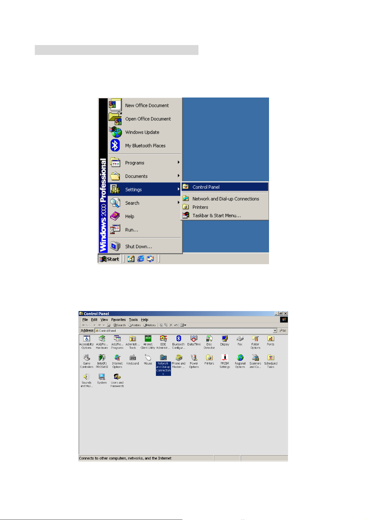
3-2-1. The Settings Under Windows2000
Step 1. Click “Start” in the desktop of the Windows to select “Settings”, and then click
“Control Panel”.
Step 2. Double click the “Network and Dial-up Connections”.
8
Page 14
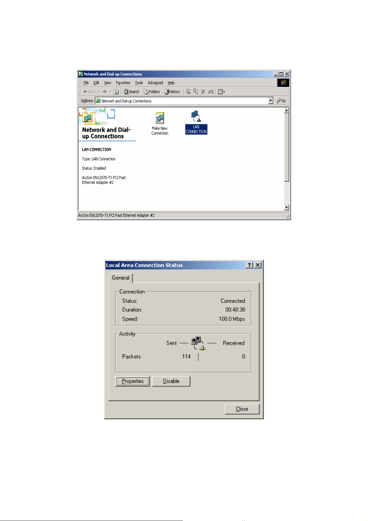
Step 3. Double click the “LAN CONNECTION”.
Step 4. Click “Properties” in the box under LAN CONNECTION Status.
9
Page 15
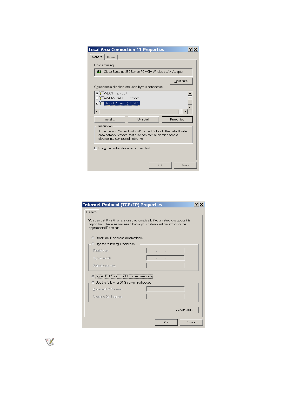
Step 5. Double click “Internet Protocol (TCP/IP)”.
Step 6. Please select “Obtain an IP address automatically” and “Obtain DNS server
address automatically”, and then press “OK”.
Now, the computer will obtain an IP address automatically from the
GN-BR404W then you can go to “Step11” directly. If you would like to obtain an
IP address manually, please refer to Step7~Step10.
10
Page 16
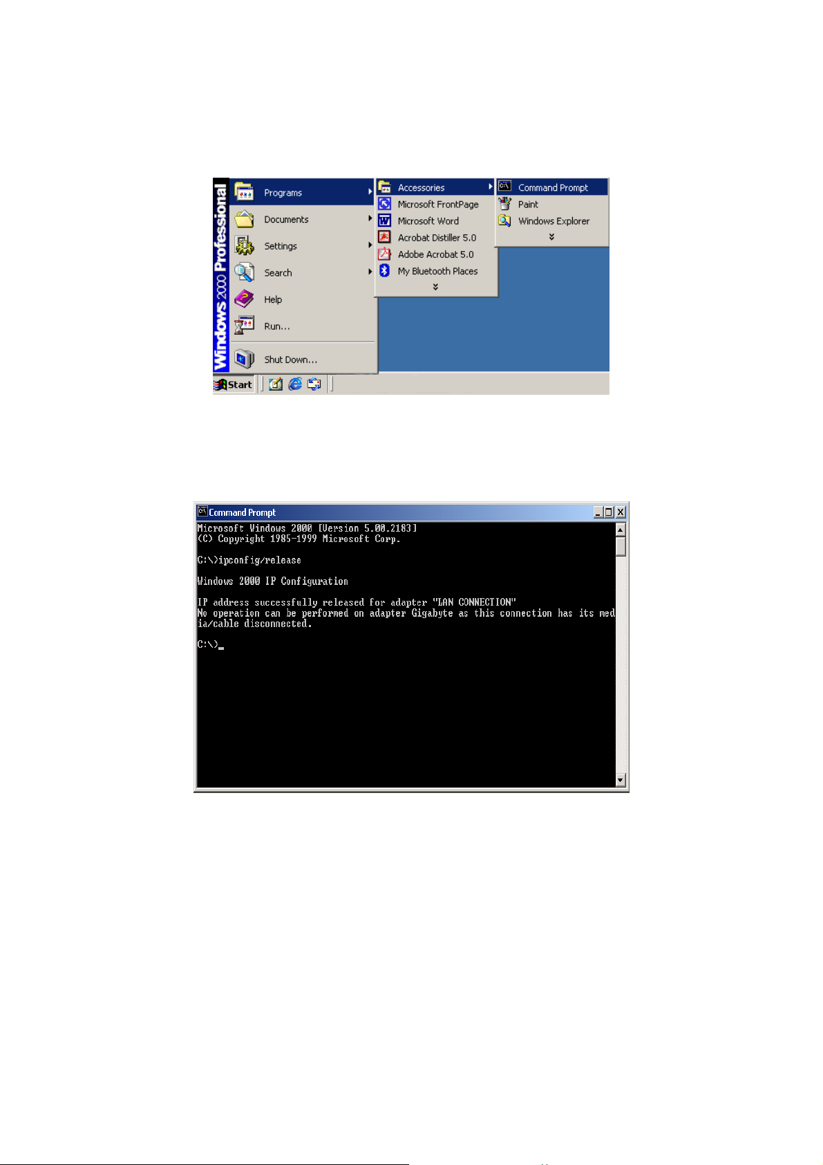
Step 7. Click “St art” at the desktop of the Windows, and then “Program”, “Accessories”,
and “Command Prompt” in sequence.
Step 8. Key in the command “ipconfig/release” in DOS mode, and then enter.
11
Page 17
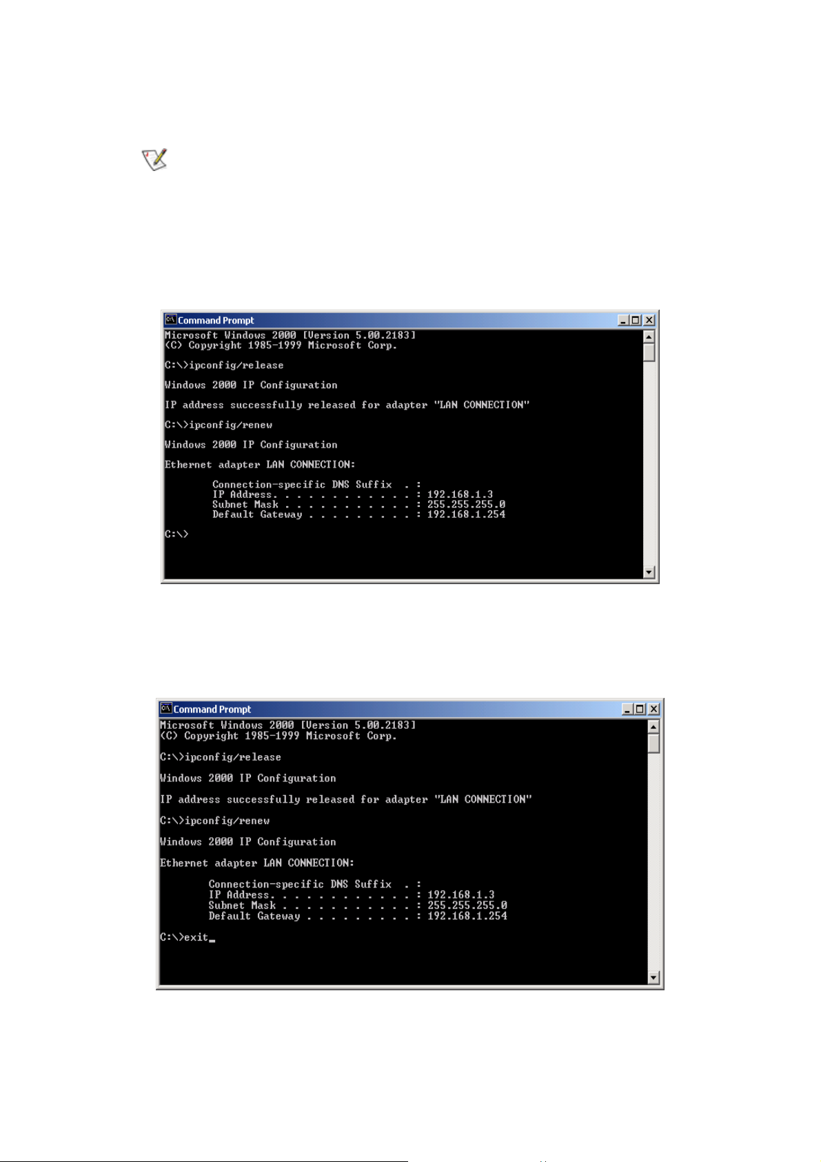
Step 9. Key in the command “ipconfig/renew” in DOS mode, and then enter.
If the IP address of the GN-BR404W is 192.168.1.254, the IP address of your
computer must be 192.168.1.X (where “X” is a number between 1 and 253.
Each computer on your network must have a different IP address within that
range where “X” represents a number between 1 and 253.) The default
gateway must be 192.168.1.254.
Step 10. Key in the command “exit” in DOS mode, and then enter.
12
Page 18
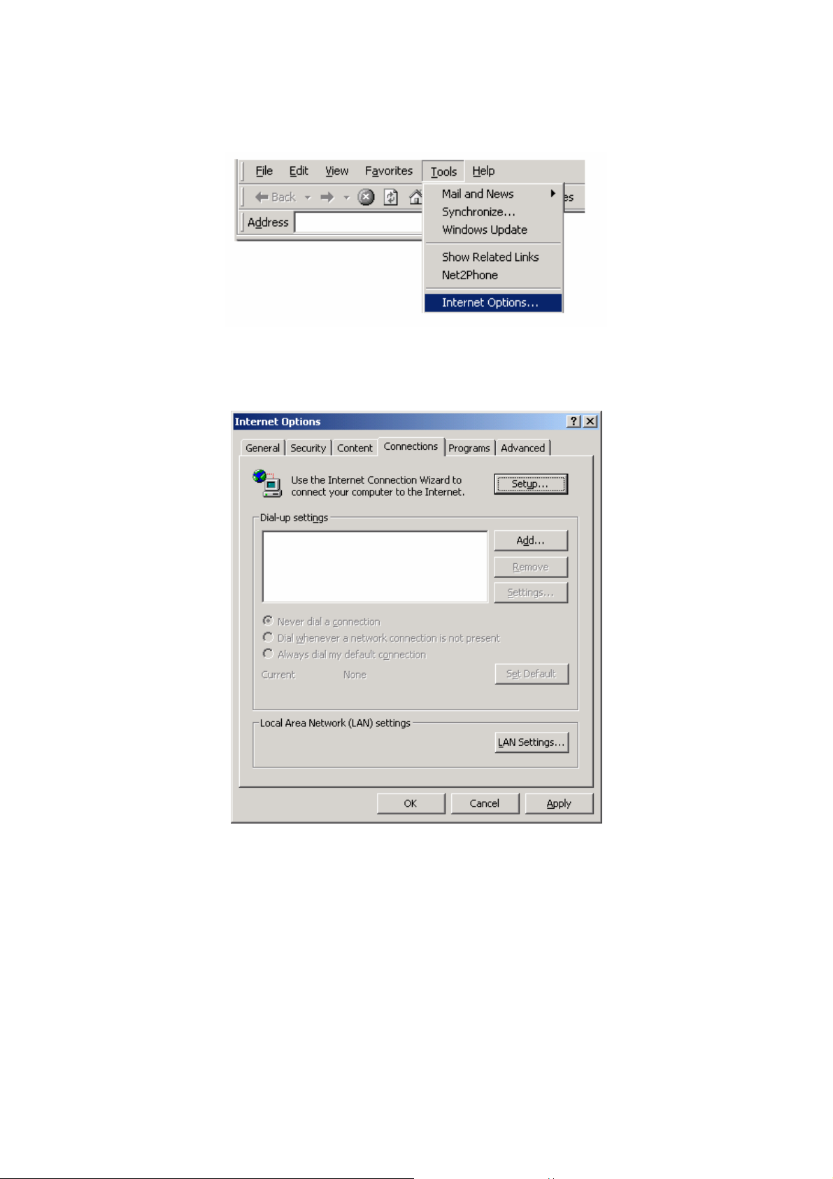
Step11. In your “Internet Explore” Browser select “Internet Options” under “Tools”.
Step 12. In this dialogue box, please click “Connections” in the “LAN Settings”.
13
Page 19
Step 13. Please DO NOT tick all of the selection boxes. Press “OK” after finishing with
the setup, and refer to Section 3-3 for setup of broadband router.
If your ISP Company has a designated Proxy setting, key in the setting after
you complete the GN-BR404W configuration.
Now, please jump to Section 3-3 to setup broadband router.
14
Page 20
3-2-2. Setup Under the Windows 95/98/Me
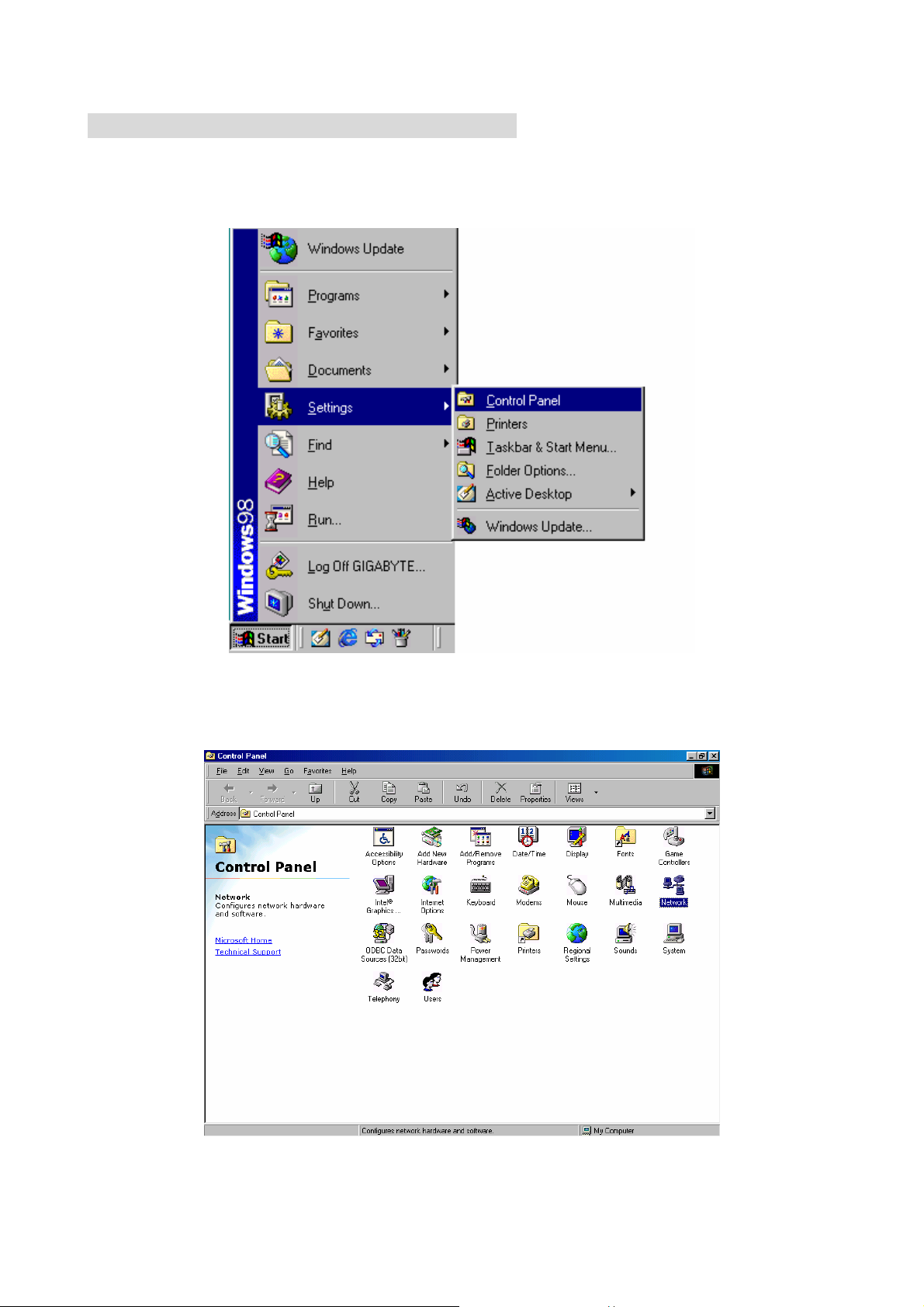
Step 1. Click “Start” at the desktop of the Windows, and select “Settings”, and then the
“Control Panel”.
Step 2. Double click “Network”.
15
Page 21
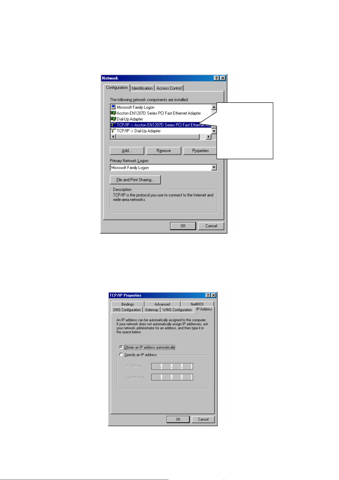
Step 3. Under Network, double click the “Configuration”, and choose your appropriate
setting “TCP/IP -> and your network card” below.
Please choose
the TCP/IP and
the name of
your network
card.
Step 4. Select “IP Address” tab. Please select “Obtain an IP address automatically”
then click “Gateway” tab.
16
Page 22
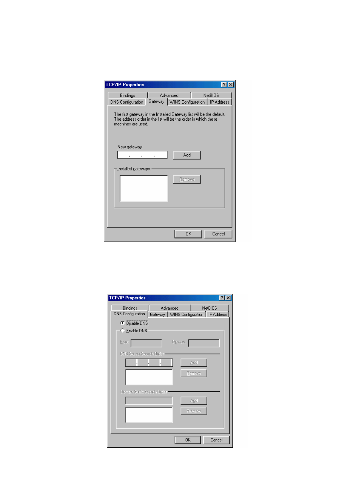
Step 5. In the window of “Gateway”, please clear all installed gateways and do not fill any
of the blanks, and then click “DNS Configuration” tab.
Step 6. In the window of “DNS Configuration”, please select “Disable DNS” and then
press “OK”.
17
Page 23
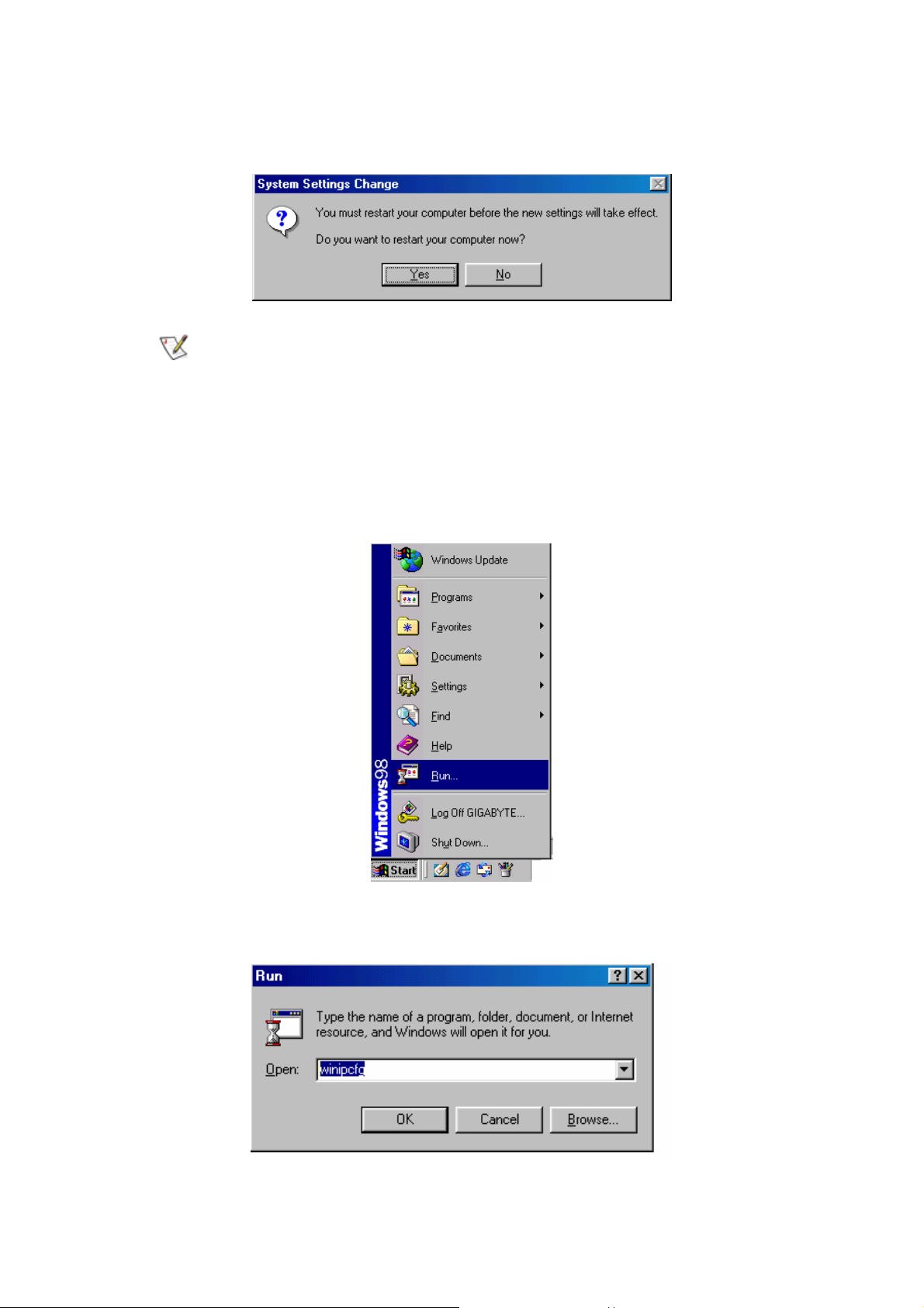
Step 7. Please press “Yes”, and reset the computer screen as follows:
After booting the computer, the computer will obtain an IP address
automatically from the GN-BR404W then you can go to “Step11” directly. If
you would like to obtain an IP address manually, please refer to
Step8~Step10.
Step 8. After booting the computer, please click “Start” and choose “Run”.
Step 9. Key in “winipcfg”, and press “OK”.
18
Page 24
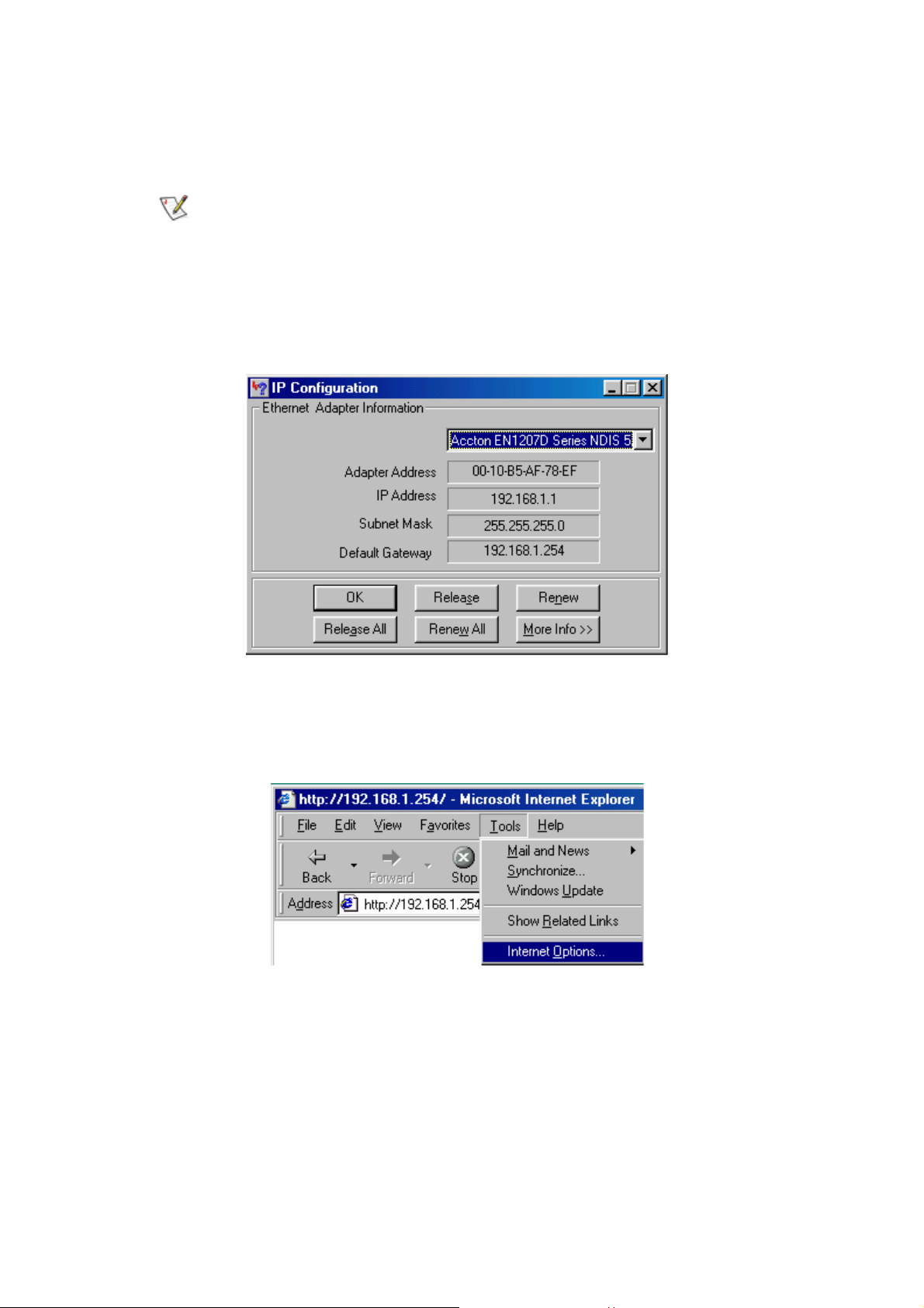
Step 10. In the pulled down menu, select your network card, press “Release All”, then
press “Renew All”, and then press “OK”.
If the IP address of the GN-BR404W is 192.168.1.254, the IP address of your
computer must be 192.168.1.X (where “X” is a number between 1 and 253.
Each computer on your network must have a different IP address within that
range where “X” represents a number between 1 and 253.) The default
gateway must be 192.168.1.254.
Step11. Please select “Internet Options” under “Tools” of your IE Browser.
19
Page 25
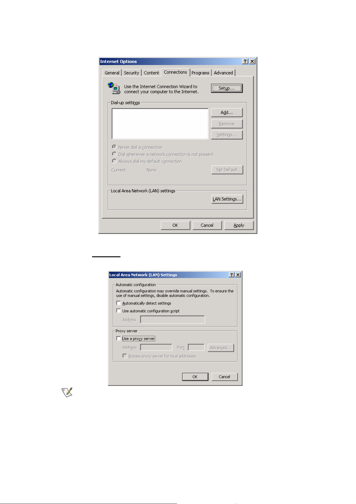
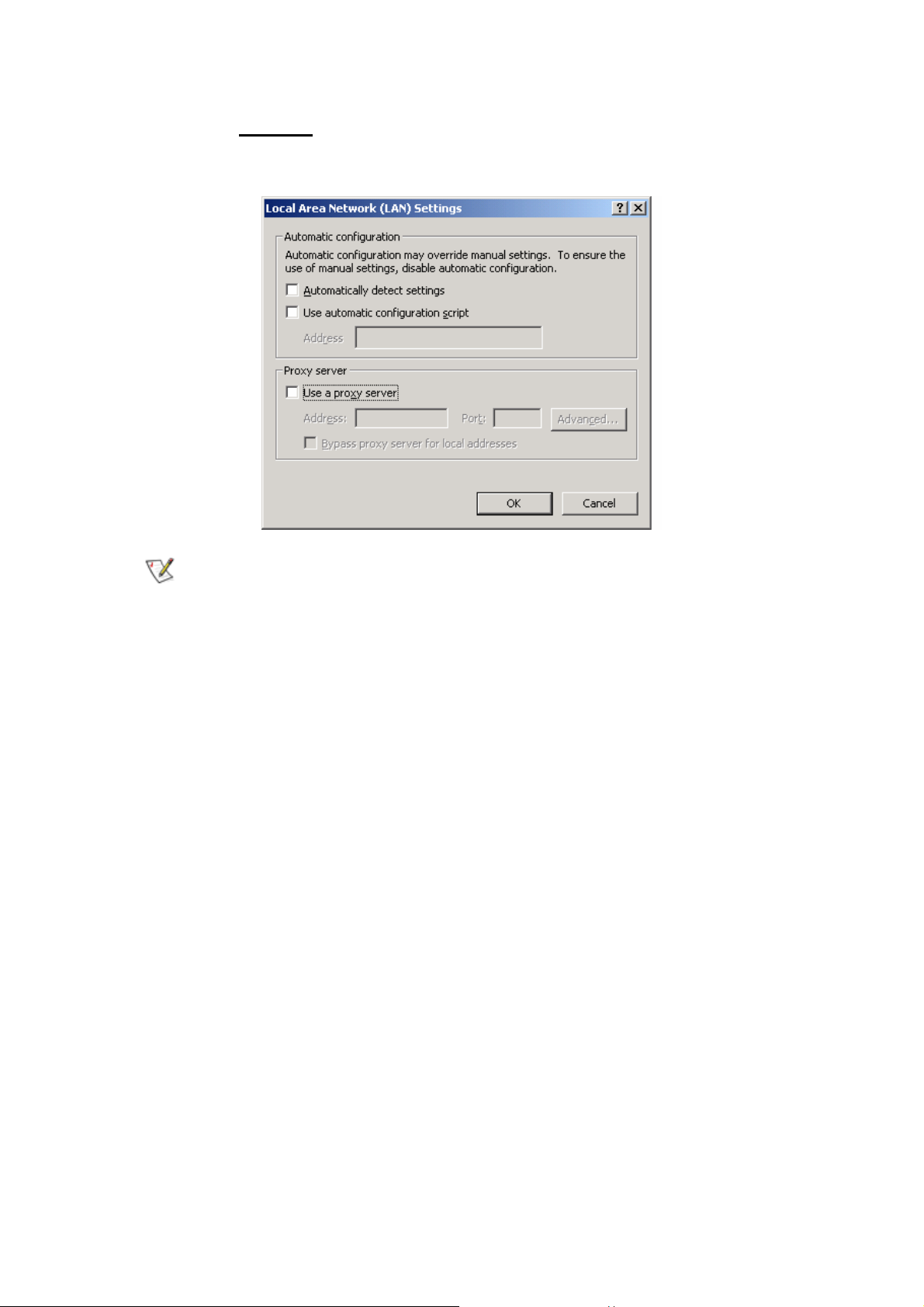
Step 12. In this dialogue box, please select “Connections” in the “LAN Settings”.
Step 13. Please
the setup, and refer to Section 3-3 for setup of broadband router.
If your ISP Company has a designated Pr oxy setting, key in the setting after
DO NOT tick all of the selection boxes. Press “OK” after finishing with
you complete the GN-BR404W configuration.
Now, please jump to Section 3-3 to setup broadband router.
20
Page 26
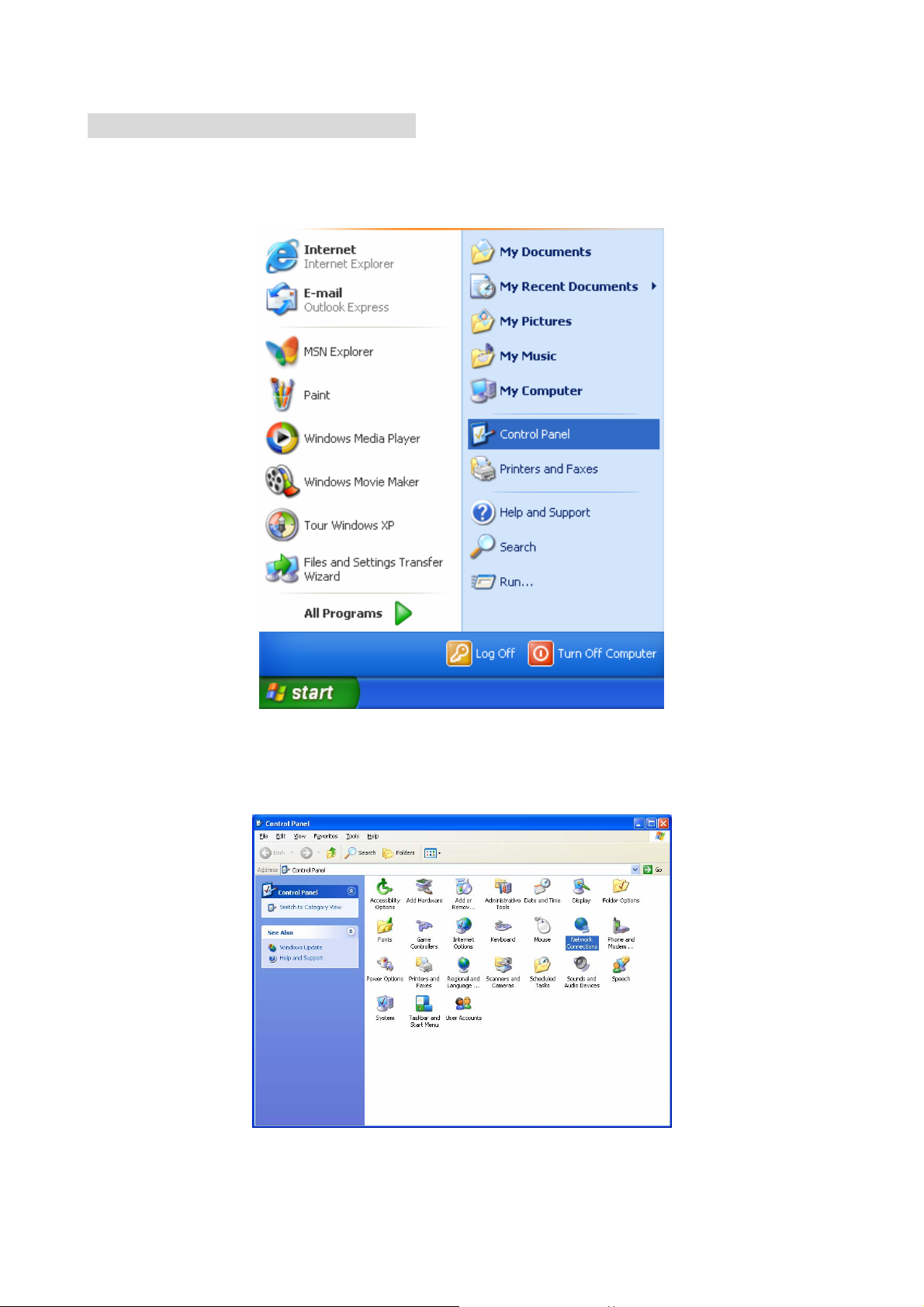
3-2-3. Setup Under Windows XP
Step 1. Click the “Start” at the desktop of the Windows, and select the “Control Panel”.
Step 2. Double click the “Network Connections”
.
21
Page 27
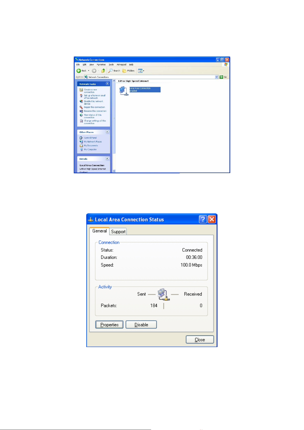
Step 3. Double click the “Local Area Connection”.
Step 4. Click the “Properties” in the box under Local Area Connection Status.
22
Page 28
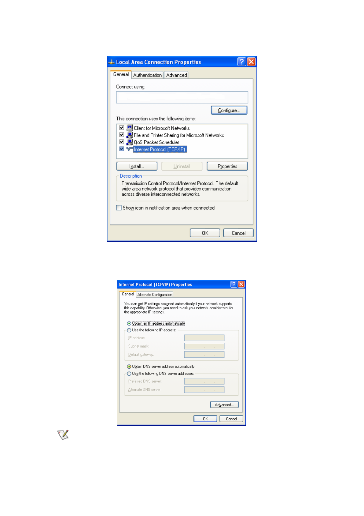
Step 5. Double click the “Internet Protocol(TCP/IP)”.
Step 6. Please select the “Obtain an IP address automatically” and “Obtain DNS
server address automatically”, and then press “OK”.
Now, the computer will obtain an IP address automatically from the
GN-BR404W then you can go to “Step11” directly. If you would like to obtain an
IP address manually, please refer to Step7~Step10.
23
Page 29
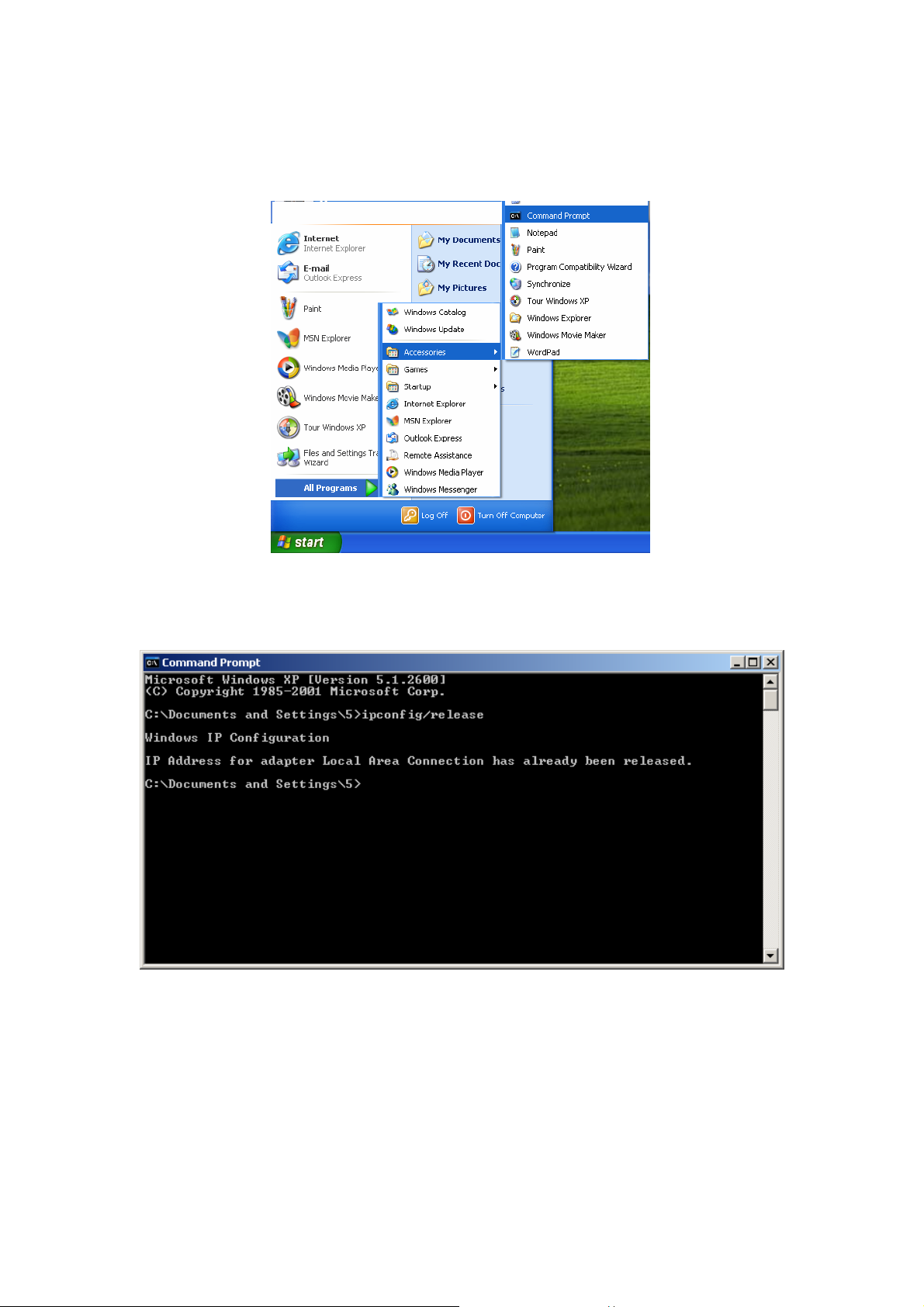
Step 7. Click the “Start” at the desktop of the Windows, and then the “Accessories”, and
then the “Command Prompt”.
Step 8. Input the “ipconfig /release” in the box of Command Prompt, and then enter.
24
Page 30
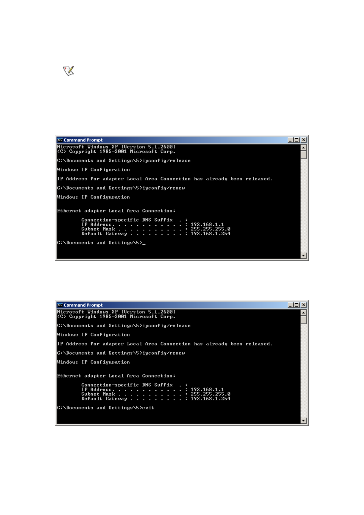
Step 9. Input “ipconfig/renew” in the box of Command Prompt, and then enter.
If the IP address of the GN-BR404W is 192.168.1.254, the IP address of your
computer must be 192.168.1.X (where “X” is a number between 1 and 253.
Each computer on your network must have a different IP address within that
range where “X” represents a number between 1 and 253.) The default
gateway must be 192.168.1.254.
Step 10. Input “exit” in the box of Command Prompt, and then press enter.
25
Page 31

Step 11. Please select “Internet Options” under “Tools” of your IE Browser.
Step 12. In this dialogue box, please select “Connections” in the “LAN Settings”.
26
Page 32

Step13. Please DO NOT tick all of the selection boxes. Press “OK” after finishing with
the setup.
If your ISP Company has a designated Proxy setting, key in the setting after
you complete the GN-BR404W configuration.
Now, please jump to Section 3-3 to setup broadband router.
27
Page 33

3-3. Setup for Broadband Router
The GN-BR404W provides Web based configuration. You can configure your GN-BR404W
through your Internet Explorer browser or Netscape Communicator.
Step 1. Key in the preset IP address“192.168.1.254” in the address column in the
browser, and then press enter.
If you have more than one router or IP conflict problem on the same subnet,
please follow the IP change priority table shown as below.
priority1 "192.168.1.254" "255.255.255.0" "192.168.1.1" "192.168.1.33"
priority2 "192.168.2.254" "255.255.255.0" "192.168.2.1" "192.168.2.33"
priority3 "172.16.1.254" "255.255.255.0" "172.16.1.1" "172.16.1.33"
priority4 "172.17.1.254" "255.255.255.0" "172.17.1.1" "172.17.1.33"
priority5 "10.1.1.254" "255.255.255.0" "10.1.1.1" "10.1.1.33"
priority6 "10.2.1.254" "255.255.255.0" "10.2.1.1" "10.2.1.33"
Step 2. The dialogue box will appear as s hown in the following diagram, and key in the
default user name “admin” for the wideband network GN-BR404W and the
default password “admin”, and then press “OK”.
28
Page 34

Step 3. The homepage of the GN-BR404W will appear as shown below. If you are the first
time to configure the router and you have connected to the WAN port, the system
will detect your wan type automatically through the “Smart Setup” function.
Please refer to the instruction of the “Smart Setup”.
If you want to configure the wan type manually, you can click the “Setup Wizard”
on the screen, and such Setup Wizard will guide you to complete the necessary
steps for the setup on screen as follows.
29
Page 35

Smart Setup
If you are the first time to configure the router and you have connected to the WAN port, the
“Smart Setup” function can detect your wan type automatically through the Internet
connection. And it will guide you to complete the wan setting step by step.
System automatic detection:
Step1. The system is detecting the WAN connection type, and will show the detective
result later.
30
Page 36

Step2. If you are the PPPoE user, the screen will appear as shown below. Please enter
the User ID and Password information that your ISP provided you.
Step3. If you are the dynamic IP address user, the device will save the configuration
and there is no necessary to reboot the device. Please click “OK” button.
31
Page 37

Step4. If you are the Static IP address user, the screen will appear as shown below.
Please enter the WAN IP address, WAN subnet mask, WAN gateway, and DNS
information that your ISP provide you.
32
Page 38

Click Smart Setup manually:
Step 1. The system is detecting the WAN connection type, and will show the detective
result later.
Step2. If you are the PPPoE user, the screen will appear as shown below. Please enter
the User ID and Password information that your ISP provided you.
33
Page 39

Step3. If you are the dynamic IP address user, the device will save the configuration
and there is no necessary to reboot the device.
Step4. If you are the Static IP address user, the screen will appear as shown below.
Please enter the WAN IP address, WAN subnet mask, WAN gateway, and DNS
information that your ISP provide you.
34
Page 40

Note: If the device can not detect the WAN Ethernet link signal, it will show the error
message. Please check the physical connection between GN-BR404W and cable
or DSL modem.
35
Page 41

Setup Wizard
Step1. “LAN Setup” is shown in the diagram. Each setup item of the local area
network is default setting, and is not necessary to make change to it for normal
operation. Please input the settings on your own if change is needed.
DHCP Setup:
- ”enable” indicates that the DHCP function of the GN-BR404W is initialized,
and you configure the computers on your network to “Obtain an IP address
automatically”, then when you turn your computer “On”, it will automatically
load the proper TCP/IP setting from GN-BR404W. (Configure the DHCP
starting address and the DHCP allocation number on your own.)
- “disable” indicates that it will not automatically load proper TCP/IP setting
from the GN-BR404W. You will have to configure all the TCP/IP setting for
your network manually. (It is not necessary to configure the DHCP starting
address and the DHCP allocation number.)
DHCP Start Address / End Address :
When the DHCP setting is “enable”, the GN-BR404W uses this allocable
range of the IP address as the initial value to assign the IP to the PC connected
to the LAN end.
For example:
The DHCP start address is 192.168.1.1 and the end address is 192.168.1.50 .
The IP allocable range of the DHCP is from 192.168.1.1 to 192.168.1.50.
The LAN IP address “192.168.1.254” is the default IP address of the
GN-BR404W.
Click “Next”, and the following screen will appear:
36
Page 42

Step 2. Choose your desir ed wide area network mode.
“PPPoE”: If you are using the hourly rate for the ADSL, please select this
And then please follow Step 3
item.
“Dynamic IP Address”: If you use the wideband fixed connection of
ADSL/Cable Modem, but do not have a static IP, please select this item.
And then please follow Step 7
“Static IP Address”: If you use the wideband fixed connection of
ADSL/Cable Modem, but have a static IP, please select this item.
please follow Step 11
“PPPoE Unnumber”: If you are the user of the PPPo E Unnumber, please
And then
select this item. And then please follow Step15.
After your desired wide area network mode is selected, please press “Next”.
37
Page 43

Step 3. If you select “PPPoE” under the WAN TYPE SELECT, key in the User ID and
password. The wideband company provides the above data, and press “Finish”
to go to next step.
PPPoE User ID and Password:
The “User ID” and “Password” are your ISP assigned to you.
38
Page 44

Step 4. Press “Reboot” to go to next step.
Step 5. Please wait a moment.
39
Page 45

Step 6. The IE browser will be automatically connecte d to the main menu, and your setup
has completed by then. Please use your IE connect to Internet.
If you can connect to the Internet , the setting is completed. If you use the
Wireless Lan Card connection or need further setting, please continue to
section 3-4 Advanced Setup.
40
Page 46

Step 7. If you select the “Dynamic IP Address” in the WAN TYPE SELECT, the
following screen will appear. Please key in the Host Name if your ISP has
provided. And then press “Finish” to go to next step.
Step 8. Press “Reboot” to go to next step.
41
Page 47

Step 9. Please wait a moment.
42
Page 48

Step 10. The IE browser will be automatically connected to the main menu, and your
setup has completed by then. Please use your IE connect to Internet.
If you can connect to the Internet , the setting is completed. If you use the
Wireless Lan Card connection or need further setting, please continue to
section 3-4 Advanced Setup.
43
Page 49

Step 11. If you select “Static IP Address” in the WAN TYPE SELECT, please key in the
data provided by the wideband company in the following fields as shown below.
And then press “Finish” to go to next step.
If your wideband company gives you more than one IP address, then select
one of them to fill in the column in the following fields.
Step 12. Press “Reboot” to go to next step.
44
Page 50

Step 13. Please wait a moment.
Step 14. The IE browser will be automatically connected to the main menu, and your
setup has completed by then. Please use your IE connect to Internet.
If you can connect to the Internet , the setting is completed. If you use the
Wireless Lan Card connection or need further setting, please continue to
section 3-4 Advanced Setup.
45
Page 51

Step 15. If you select “PPPoE Unnumber” in the WAN TYPE SELECT, please key in the
data provided by the wideband company in the following fields as shown below.
And then press “Finish” to go to next step.
If your wideband company gives you more than one IP address, then select
one of them to fill in the column in the following fields.
Step 16. Press “Reboot” to go to next step.
46
Page 52

Step 17. Please wait a moment.
Step 18. The IE browser will be automatically connected to the main menu, and your
setup has completed by then. Please use your IE connect to Internet.
If you can connect to the Internet , the setting is completed. If you use the
Wireless Lan Card connection or need further setting, please continue to
section 3-4 Advanced Setup.
47
Page 53

3-4. Advanced Setup
This section will show you the advanced setup of the GN-BR404W if you need require
special configuration.
3-4-1. Network Configuration
The Network Configuration function allows you to access to the LAN Configuration, WAN
Confguration and Multisession Configuration.
LAN Configuration
LAN Configuration
From this table, you can modify the LAN setting if it necessary.
Force IP-MAC Mapping
This Function allows you to assign a specific IP address to one specific PC.
Verify the desired setting and then click the “Submit” button to set the value into
GN-BR404W.
48
Page 54

WAN Configuration
This page is the further configuration of the WAN connection. You can setup up to 4
WAN connection entries. Each entry may has it’s own connection type (PPPoE,
PPPoE Unnumber, Dynamic IP address, Static IP address) and some other properties.
For example, when you click the “Edit” button of the ISP No.1 (WAN Type: Dynamic IP
Address) on the table then there will appear the screen as follows.
Click “Next”.
49
Page 55

ISP Name, Host Name, Gateway, DNS1 and DNS2 Address, DNS Domain
Name
Those information are provided by your ISP company.
MTU(Maximum Transmission Unit)
This defines the maximum size of the packets sent from your computer onto the
network. Any messages larger than the MTU are divided into smaller packets
before being sent. Leave this on the default value(1500) unless you have a
particular reason to change it.
NAT Setup
The Internet is expanding at an exponential rate. As the amount of information and
resources increases, it is becoming a requirement for even the smallest
businesses and homes to connect to the Internet.
Network Address Translation
(NAT) is a method of connecting multiple computers to the Internet (or any other IP
network) using one IP address. This allows home users and small businesses to
connect their network to the Internet cheaply and efficiently.
Universal Plug and Play (UPnP) is an architecture for pervasive peer-to-peer
network connectivity of PCs and intelligent devices or appliances, particularly
within the home. UPnP builds on Internet standards and technologies, such as
TCP/IP, HTTP, and XML, to enable these devices to automatically connect with
one another and work together to make networking - particularly home networking
50
Page 56

- possible for more people.
Normal user please select “NAT enable” or “UPnP&NAT” then connect to the
Internet in general.
UPnP Delete Time
This variable determines the time to live in hours of a port-mapping lease when the
value of Lease Time is 0.
Note: If the WAN IP address which got form a DHCP server and the LAN IP address
are on the same subnet, the LAN IP address will be changed to another subnet
automatically and reboot the device.
Verify the desired setting and then click the “Finish” button to set the value into
GN-BR404W.
Other WAN Type of the WAN configuration:
PPPoE
ISP Name, User ID, Password, Service Name, AC Name, DNS1 and DNS2
Address, DNS Domain Name
Those information are provided by your ISP company.
51
Page 57

Authentication Type
You may choose between “Auto”, “CHAP” and “PAP”. The default is set to “Auto”.
Challenge Handshake Authentication Protocol(CHAP). This is the preferred
method of authentication for PPP dialup links. With CHAP, the server sends a
challenge to which the remote router sends an encrypted reply containing a secret
key.
Password Authentication Protocol(PAP) is a simple authentication protocol for PPP
allowing a router to identify itself with another router by sending a simple name and
password combination. PAP is defined in RFC1334.
Connection
“Automatic” It connects to an ISP without delay when the router is turned on. If
connection is disconnected by something troubles, connection have
to retry to connect automatically.
“Manual” It connects to an ISP when user presses the “connection” button. If
connection is disconnected by something troubles, connection have
to stop.
52
Page 58

Static IP Address
ISP Name, WAN IP Address, WAN Subnet Mask, WAN Gateway, DNS1 and
DNS2, DNS Domain Name
Those information are provided by your ISP company. If your ISP company gives
you more than one IP address, and then select one of them to fill in the above
form.
53
Page 59

PPPoE Unnumber
PPPoE unnumbered is a kind of PPPoE service provide by ISP. Using PPPoe
unnumbered, customer could having more than 1 global IP address. Maybe 8 or 16, or
more, it's all depend on ISP's server policy. One of these address should use for
router's wan IP address, others could be use behind the router.
ISP Name, User ID, Password, Service Name, AC Name, DNS1 and DNS2,
DNS Domain Name, WAN IP Address, WAN Subnet Mask
Those information are provided by your ISP company.
54
Page 60

Multisession Configuration
The Multisession configuration allows you to setup the priority of WAN connection after
you complete the WAN configuration. In our PPPoE multi-session, three connections
will be established in three visual interfaces. Each interface owns ip address, gateway
and netmask belong each sub network. So we can use a set of rule to routing packet.
Which packets all information is matched of rules, it will be routing to different gateway.
On the PPPoE connection when established one connection peer to peer is call
session. If we have multi PPPoE connect at the same time. We must have way to
manager each session.
Backup Session
User can set the alternate session to the main session as the backup session.
In addition, if main session is fail to connection a backup session is replace main
session.
For example,
The main session could not connect to an ISP.
Further the backup session could not connect too, the main session
Automatic : main -> backup->main->backup…….
Manual : main->backup (Backup tries to connect once only.)
Session keep alive was no response after the main session connected. Sub1 or
55
Page 61

Sub2 session have no backup sessions. Backup session can be set the main
session only.
Note: The backup session can be specified LAN type connection.
Our priority of rule
SUB2 > SUB1 >MAIN
In other words, every packets pass thought the router would be matching SUB2
rule first. If it is match, packet next hop will be change to SUB2 session gateway. If
it is not, the Router check packet information matched with SUB1 rule. If it still not
matched that will be route to main session gateway.
Note:
1. Rule could be overlap for any condition.
2. All of rule in one session must be match.
3. Check order is SUB2->SUB1->MAIN, if any session rules matched. It will
jump out the check order.
4. Main session is default session. All of packets match fail will be group under
main session.
Exception:
1. If sub session connection fail, the rule also to break down. Another session
route path is alive. Packet will pass thought this session. It seems backup the
sub session use main or sub1.
2. If main session is unlink or connection fail, sub1 and sub2 still by pass the
match packet.
3. Each session are independent with NAT address translation.
The method of setting IP address:
IP Address Description
* All IP address
192.168.1.3 Specific IP address
192.168.1.0/24 Network address(24bit netmask)
Range assigned
192.168.1.3−192.168.1.33
Separated by “−” ; no space
To allocate
192.168.1.3,192.168.0.8
Separated by comma “,” ; no space
56
Page 62

No assigned Ignored
The method of setting Host Name: (The destination IP can be assign to the IP
address or Host name)
For example as follows:
Host Name
.tw
.com.tw
www.gigabyte.com.tw
host1.www.gigabyte.com.tw
www.*.com.tw
No assigned
The method of setting Port:
IP Address Description
* All ports
80 Specific port
Range assigned
80−110
Separated by “−” ; no space
To allocate
80,8088
Separated by comma “,” ; no space
No assigned Ignored
57
Page 63

3-4-2. Wireless Configuration
Wireless LAN Configuration
Region
Because of the different region has a different open channel regulation, please
check whether the default region value is your local area. If it did not appear
properly region please contact your local distributor or authorized reseller
immediately.
HW info
The information of the Wireless Lan Card.
RF Type
The option of the RF type is depend on your WLAN Card. If your WLAN Card
supports the network standards of IEEE 802.11b and 802.11g, then the option will
have two setting you can select.
Channel
Please choose the channel, which you can get best performance. Normally, it
doesn’t need to change. The default value is channel 6.
58
Page 64

SSID
The SSID is the name represent the router in the wireless network. This SSID
string is case sinsitive of up to 32 ASCII characters. The default value is
“GIGABYTE”, if the setup value is the default value, like “router”. Only can accept
the computer connection, which use the wireless card SSID (or ESSID) set up, is
“router”.
Rate
You can select one of the rates among 1M, 2M, 5.5M and 11M based on your need.
The default value is “auto/best”.
Hidden SSID
This setting allows you to hide the SSID in wireless transmission. Those who don’t
know the SSID will be able connect to the router. The default value is “disable”.
Authentication Type
You may choose between “Open System”, “Shared Key”, “WPA Radius with
802.1x” and “WPA Pre-shared key”. The Authentication Type default is set to
“Open System”.
Open System, in which the sender and the recipient do NOT share a secret key.
Each party generates its own key-pair and asks the receiver to accept the
randomly generated key. Once accepted, this key is used for a short time only.
Then a new key is generated and agreed upon.
Shared Key is both the sender and the recipient share a secret key.
If the “Shared Key” option is selected, and then the option “disable” of the WEP
will be disabled.
WPA adius with 802.1x, if you have been using Wi-Fi for a while, you are probably
familiar with the 802.1X authentication protocol. This protocol allows users to
authenticate into a wireless network by means of a RADIUS Server. In standard
Wi-Fi, 802.1X authentication is optional. However, 802.1X authentication is a
requirement for WPA. If your environment does not have a RADIUS server in place,
you can still use WPA in spite of the 802.1X requirement. As an alternative to
RADIUS, WPA supports the use of a preshared key.
59
Page 65

WPA Pre-shared key, One of the biggest drawbacks to traditional WEP security is
that changing the encryption key is optional. Even if you do switch encryption keys
from time to time, there is no option for globally rekeying all access points and all
wireless NICs.
Instead, rekeying is a tedious manual process and is completely impractical for
large organizations. After all, the instant you rekey an access point, none of the
clients will be able to access it until they are also rekeyed.
But with WPA, the rekeying of global encryption keys is required. In the case of
unicast traffic, the encryption key is changed after every frame using Temporary
Key Integrity Protocol (TKIP). This protocol allows key changes to occur on a
frame by frame basis and to be automatically synchronized between the access
point and the wireless client. Global rekeying works by advertising the new keys to
wireless clients.
The TKIP is really the heart and soul of WPA security. TKIP replaces WEP
encryption. And although WEP is optional in standard Wi-Fi, TKIP is required in
WPA. The TKIP encryption algorithm is stronger than the one used by WEP but
works by using the same hardware-based calculation mechanisms WEP uses.
The TKIP protocol actually has several functions. First, it determines which
encryption keys will be used and then verifies the client's security configuration.
Second, it is responsible for changing the unicast encryption key for each frame.
Finally, TKIP sets a unique starting key for each authenticated client that is using a
preshared key.
WEP Key
Protects your information with the highest level of industry-standard WEP
encryption: 64/128/152-bit for 802.11b standard, and up to 152-bit for 802.11g
standards. When the “Disable” is selected there is no WEP encryption. When
“64bits”, “128bits” or “152bits” selected there is encrypted date transfer to prevent
unauthorized user to access the wireless network.
There are three levels of encryption 64 bits, 128 bits and 152bits. The 64 bits
encryption is referenced as a lower level encryption. The 152 bits encryption is
referenced as a higher level encryption.
The 64 bits WEP encryption use 40 bits as a secret key, which can controlled by
user, and 24 bits as the initialize vector, which user can not control. These two
portions plus together is 64 bits encryption. Some other vendor’s product might
refer as 40 bits encryption. It is the same thing.
60
Page 66

The 128 bits WEP encryption use 104 bits as a secret key, which can controlled by
user, and 24 bits as the initialize vector, which user can not control. These two
portions plus together is 128 bits encryption. Some other vendor’s product might
refer as 104 bits encryption. It is the same thing.
The 152 bits WEP encryption use 128 bits as a secret key, which can controlled by
user, and 24 bits as the initialize vector, which user can not control. The 152 bits
WEP encryption spawns a KEY ID containing 32 HEX digits.
MAC Access Control of the Wireless
The MAC Access Control allows the router to define up to 32 hosts which are allowed
to access to the WAN port. To disable the MAC Access Control function, keep the
default value, Disable. To set up a MAC setting, click Enable.
61
Page 67

802.1x
802.1x authentication for wireless LANs provides centralized, server-based
athentication of end users.
1) A client sends a “start” message to a router, which requests the identity of the
client.
2) The client replies with a response packet containing an identity, and the router
forwards the packet to an authentication server.
3) The authentication server sends an “accept” packet to the router.
4) The router places the client port in authorized state, and traffic is allowed to
proceed.
RADIUS server IP
Please assign a IP address to the RADIUS server IP(authentication server).
RADIUS server Port
The setting range is 1~65536.
62
Page 68

Shared sercet
This filed can key in up to 256 character.
Rekey
Under this option two setting are possible: “enable” or “disable”. The default value
is “enable”.
WDS
Wiring is headache and complex problem on the Networking environment all the time.
The Wireless Access Point solves the connection problem between end-users and the
backbone of the network. But it still is requiring establishing a wired backbone network
on this framework.
Wireless Distribution System (WDS), the technology provide a method that use
“Wireless” to take place of the wired backbone networking, allows several of the
access points to compose a wide Wireless LAN network. However, even if the general
business or home use, the access point with WDS function has decreased the
difficultly of the wired wiring. On the real network environment, it is still need to use
wired method to connect router and access point when they want to link ISP to
Internet.
In order to built an entire wireless solution to get rid of the wiring problem. Integrate the
technology of the WDS and Routers that connect the routers and access points
through the WDS has created the concept of the Wireless Distribution.
Advantage:
1. Convenience Environment: It gets rid of the wiring problem and allows all devices
to connect through the Wireless LAN except the connection between the ISP and
routers on the networking environment.
2. Strong expansibility: It can expand the network just add new access point directly
where needs to have the network.
63
Page 69

ISP
Router
Extended Distributed
Wireless Systems(EDWS)
AP
AP
AP
WDS could be used for extend wireless ambit for router. For example, router locate at
floor 1, but the radio's range can't reach floor 3. In this case, customer can deploy a
access point at floor 2 and then enable WDS function of router. Then, user at floor 3
can connect to rooter at floor 1 though access point at floor 2.
64
Page 70

3-4-3. Routing Table
RIP Configuration
RIP(Routing Information Protocol) is a dynamic internetwork routing protocol primary
used in interior routing environments. A dynamic routing protocol, as opposed to a
static routing protocol, automatically discovers routes and builds routing tables.
Static Routing Table
Under some of Internet environments, some of the subnet do not go through the
default gateway. Users can add those routing information to Static Routing Table
themselves.
Destination IP
The Destination IP address is the address of the network or host to which the
static route is assigned.
Netmask
The Netmask determines which portion of a destination LAN IP address is the
network portion, and which portion is the host portion.
65
Page 71

Gateway
Metric
This is the IP address of the gateway device that allows for contact between the
router and the network or host.
Type a numeber between 1 and 15 as the Metric value. This represents the
number of routers between your network and the destination. Usually, a setting of
2 or 3 works, but if this is a direct connection, set is to 1. The default value is 1.
Verify the desired setting and then click the “Submit” button to set the value into
GN-BR404W.
66
Page 72

3-4-4. Virtual Server
Virtual server setting split into two different case. Case 1 is router having only 1 global IP
address, PPPoE/DHCP/Static is this case. Case 2 is router having more than 1 global IP
address, normal having 8 or 16 IP address, PPPoE unnumbered is this case. In case 1,
virtual server only need to configure LAN host information, because WAN IP address
always the same, but in case 2, virtual server also need to configure which WAN IP address
need redirect to internal LAN host.
DMZ Support of the Virtual Server
If you have a computer that cannot run an Internet application (e.g. internet game,
vedio conferencing, or VPN connections) properly from behind the NAT firewall, or set
up a server which can connect to the Internet in the Intranet then you can open the
computer up to unrestricted two-way Internet access.To use the DMZ, you have to set
a static IP address for the computer. The IP Address (such as 192.168.1.2) of the
computer at the LAN terminal can be used to input to the field of LAN IP Address.
Verify the desired setting and then click the “Submit” button to set the value into
GN-BR404W.
67
Page 73

PPPoE/DHCP/Static Type of the Virtual Server
Virtual Server provides a way to let the PC at the WAN end connect to a server of a PC
at the LAN end. Taking the IP address 192.168.1.1 of a PC on a FTP at the LAN for
example:
x Protocol: TCP
x Port: 21
x Vitrual Server IP: 192.168.1.1
x Enable: enable
The PC at the WAN end can connect to the internal FTP server at the IP address
192.168.1.1 via the WAN end of the IP address of the FTP BR404W.
Interface :
* means “all”,
1 means “Main session”,
2 means “Sub1 session”,
3 means “Sub2 session”
68
Page 74

PPPoE Unnumber Type of the Virtual Server
The PPPoE Unnumer user may have multiple global IP addresses, therefore each IP
address needs to setup specifically.
Your ISP may provides you a group of the Global IP,
e.g. 61.222.10.1 ~ 61.222.10.7(But only can use 61.222.10.2~61.222.10.6)
Taking the IP address 192.168.1.1 of a PC on a FTP at the LAN for example:
x Global IP: 61.222.10.2
x Protocol: TCP
x Port: 21
x Vitrual Server IP: 192.168.1.1
x Enable: enable
The PC at the Global IP 61.222.10.2 can connect to the internal FTP server at the IP
address 192.168.1.1 via the WAN end of the IP address of the FTP BR404W.
69
Page 75

3-4-5. Firewall Rule
The Firewall Rule allows you to configure your own security policy to prevent unauthorized
Internet users from accessing private networks or corporate LAN’s and Intranets.
Security Configuration
The security configuration provides a security list for you configure, includes Security
One-Touch Setting, Stealth Mode, and Unlawful Computer Access Detection.
From this security setting list, you can check which you want and then click “Submit”
button to set the value into GN-BR404W.
Note: "URL Blocking" function will not work when any of the item from "Security
one-touch setting" as well as the" The full state packet inspection is used"
under "Unlawful computer access detection" function is clicked.
70
Page 76

VPN Pass Through
Virtual private networks (VPN)are secured private network connections, built on top of
publicly-accessible infrastructure, such as the Internet or the public telephone network.
VPNs typically employ some combination of encryption, digital certificates, strong user
authentication and access control to provide security to the traffic they carry. They
usually provide connectivity to many machines behind a gateway or firewall.
GN-BR404W supports Internet-industry standards technology to provide customers
with open interoperable VPN solutions such as Internet Protocol Security (IPSec) and
Layer 2 Tunneling Protocol (L2TP) as well as Point-to-Point Tunneling Protocol
(PPTP).
PPTP Pass Through setting
PPTP stands for Point-to-Point Tunneling Protocol. It basically allows you to
establish a connection to a corporate network and you can share files and other
data as if your machine were actually on that local network.
IPSec Pass Through setting
IPSec stands for IP Security. It provides authentication and encryption over the
Internet. It functions at Layer 3 and thus secures everything on the network. It has
become a standard protocol used for virtual private networks (VPNs).
71
Page 77

L2TP Pass Through setting
L2TP stands for Layer 2 Tunneling Protocol. It is an extension of the Point-to-Point
Tunneling Protocol and is also used to establish virtual private networks.
Enable/Disable VPN pass through. If administrator configure a host to enable VPN
pass through, router will automatically setting virtual server and firewall setting for this
host. All VPN packets will be transparent and will redirect to this host. VPN pass
through works, either VPN server behind the LAN side or VPN server locate at WAN
side. For different VPN pass through setting, only 1 host can be configured as pass
through.
Static Rule
This screen allows you to edit the firewall rule table manually. It helps protect your local
network against attack from outside and provides a method of restricting users on the
local network from accessing the Internet. Additionally, it can filter out specific packets
to trigger the router to place an outgoing connection. Please click “Add” to edit the rule
table, there will appear the screen as shown below.
72
Page 78

Rule Number (No.)
From 1~64, rule 1 has highest priority, rule 64 has lowest priority
Policy
Under this option two settings are possible: “accept” or “drop”.
Direction
Sets the direction of packet flow. For the Data Filter:
a. W->L, WAN to LAN, specifies the rule for filtering incoming packets.
b. L->W, LAN to WAN, specifies the rule for filtering outgoing packets.
Protocol
Specifies the protocol(s) this static rule will apply to. Under this option eight
settings are possible: “TCP”, “UDP”, “TCP & UDP”, “TCPEST”, “ICMP”, “GRE”,
“ESP”, “*”.
Log
Enable or disable the log function for this rule.
Verify the desired setting and then click the “Submit” button to set the value into
GN-BR404W.
73
Page 79

3-4-6. DNS Configuration
DNS Replay
The default value of the DNS replay is “Enable”. The DNS query packets will send
through the router. When a DNS query packet enters the router, and the router will
sends an answer to the host that sent the DNS query packet. And then users have to
set the IP address of the router as the IP address of the DNS.
Dynamic DNS
The Router offers a Dynamic Domain Name Server service. The Dynamic DNS allows
you to assign a fixed host and domain name to a dynamic Internet IP address. It is very
useful when combined with the “Virtual Servers” feature. It allows Internet users to
contact to your virtual severs using a URL, rather than an IP address. Before you to
use this feature, please register for an account with one of the dynamic DNS service at
http://www.dyndns.org.
1. You can Disable or Enable the Dynamic DNS service.
2. Select the name of your dynamic DNS service provider.
3. Type the Domain Name(or Host N ame) that your dynamic DNS provider gave you.
4. Type the login Name(or Username) and Password for your dynamic DNS account.
5. If your dynamic DNS provider allows the use of wildcards in resolving your URL,
you may select the Enable wildcard to active this function.
74
Page 80

3-4-7 URL Blocking Configuration
The Router allows you to restrict access based on web address and web address
keywords.
1. To disable the URL Blocking function, keep the default value, Disable. To set up a
URL Blocking setting, click Enable.
2. To type a keyword or domain in the Keyword box.
Verify the desired setting and then click the “Submit” button to set the value into
GN-BR404W. Or you can click “Reset URL Blocking” to reset the URL Blocking
configuration.
After you configure the URL Blocking, please reboot the Router.
Note: "URL Blocking" function will not work when any of the item from "Security
one-touch setting" as well as the " The full state packet inspection is used" under
"Unlawful computer access detection" function is clicked.
75
Page 81

3-4-8 VPN Configuration
A VPN is a secure, private communication tunnel between two or more devices across a
public network (like the Internet). These VPN devices can be either a computer running
VPN software or a special device like a VPN enabled router. It allows your home computer
to be connected to your office network or can allow two home computers in different
locations to connect to each over the Internet.
Clients and Servers
A VPN server is a piece of hardware or software that can acts as a gateway into a whole
network or a single computer. It is generally ‘always on’ and listening for VPN clients to
connect to it.
A VPN Client is most often a piece of software but can be hardware too. A client initiates a
‘call’ to the server and logs on. Then the client computer can server network can
communicate. They are on the same ‘virtual’ network. Many broadband routers can 'pass'
one or more VPN sessions from your LAN to the Internet. Each router handles this
differently.
The Gigabyte router is a IPSec VPN which support following function:
1. Groups for Diffie-Hellman key negotiation - group 2, modp 1024-bit
2. Encryption transforms - Triple DES
3. Authentication transforms -HMAC using MD5
76
Page 82

Click “Add” button to add a new VPN.
Name You can give a name for the VPN.
Source Subnet/Netmask Enter the router’s subnet.
Destination Address
Gateway to Gateway Mode, allows you to setup the connection of the router to
another router. Please enter the remote(router2) IP address, Gateway address
and subnet netmask.
Host to Gateway, allows the PCs connect to the router.
Authentication Type (Preshare Key) Please enter a key for the router to authorize each
other.
Verify the desired setting and then click the “Submit” button to set the value into
GN-BR404W.
77
Page 83

Click the VPN hyperlink to edit the VPN configuration.
Click to edit the
VPN configuration.
78
Page 84

3-5. Management Tool
This section will show you how to use the management tool to manage and maintain your
wireless broadband router.
3-5-1. PPP Monitor
The PPP Monitor will show you the WAN connection status. We can disconnect ppp
anytime by pressing the “disconnection” button. We also can connect to an ISP again by
pressing the “connection” button. When each session connects to an ISP again, each
session, which are main, sub1or sub2, inherits the attribute of previous connection.
79
Page 85

3-5-2. Reboot
This function allows you to restart the GN-BR404W.
80
Page 86

3-5-3. Initilization
You can use this function to initial the router to factory defult value. Or you can press the
“init” botton on the GN-BR404W about 5sec, then the router will be restart and the system
setting will restore to the factory default value.
81
Page 87

3-5-4. Change Password
User can change the administration password of the GN-BR404W to prevent other user
access to the GN-BR404W. Please enter the account and a new password and confirm the
password and then click “Submit”. You have to enter this new password to log in when you
want to configure the GN-BR404W next time.
82
Page 88

3-5-5. Change WAN MAC
If your ISP company asks you to use the original MAC address. You can select the “Assign
WAN MAC” and enter the “New WAN MAC Address”. The MAC address is from your
Network Interface Card (NIC) that you registered with your ISP company. If you want to
restore to the factory default value, please select “Restore Default WAN MAC”. Verify the
desired setting and then click the “Submit” button.
83
Page 89

3-5-6. Upgrade Firmware
This tool allows you to upgrade the latest firmware of the GN-BR404W using a file provided
by Gigabyte. You can download the upgraded firmware version from Gigabyte website.
Please click “Browse” and select your desired upgrade file (firmware version), and then
click “Upgrade”.
84
Page 90

3-5-7. BackUp Restore
The “BackUP” button allows you to save the configuration of the GN-BR404W to a temp file
on your PC. You can then click the “Restore” button to restore the saved backup
configuration file.
85
Page 91

3-5-8. Log Information
From here, you can veiw the record of the firewall log, WAN connection and the UPnP log.
If you want to reload the data of the log list, please click “Check Again” button.
Firewall Log
WAN Connection
86
Page 92

UPnP Log
3-5-9. Save Maintenance
Please save the log and the status information if you have the support requirement. And
then send this file to Gigabyte supporting team for further investigation your question.
87
Page 93

3-5-10. Ping
This “Ping” tool allows you to verify the status of the IP address on the network. Please
enter a IP address then click “Ping”.
88
Page 94

3-5-11 Help
The Help tool can guide you the configuration information of the router.
3-5-12 About
This page show you the product name and firmware version.
89
Page 95

3-6. Status
You can use this status screen to view the router’s current connection status.and
configuration. The main menu includes LAN information, DHCP information, WAN
configuration information, LAN Ethernet Status, WAN Ethernet Status, Wireless Status,
ARP Table, DHCP Lease Table, Routing Table and UPnP Mapping Table.
LAN Ethernet Status
90
Page 96

MAC This field displays the MAC address being used by the LAN port of the router.
MTU The maximum size of the packets sent from your computer onto the network.
Rx packets The number of the packets received on this port since reset or manual
clear.
Tx packets The number of packets transmitted on this port since reset or manual
clear.
Rx bytes The current reception bandwidth used on the LAN ports.
Tx bytes The current transmission bandwidth used on the LAN ports.
WAN Ethernet Status
MAC This field displays the MAC address being used by the WAN port of the router.
MTU The maximum size of the packets sent from your computer onto the network.
Rx packets The number of the packets received on this port since reset or manual
clear.
Tx packets The number of packets transmitted on this port since reset or manual
clear.
Rx bytes The current reception bandwidth used on the WAN ports.
91
Page 97

Tx bytes The current transmission bandwidth used on the WAN ports.
Wireless Status
From this page, you can get the current Wireless LAN connection information.
ARP Table
The ARP Table will show you the mapping of the IP address and MAC address of the
PCs.
92
Page 98

DHCP Lease Table
From this table, you can get the information of the IP assignment.
Routing Table
The Routing table can show you the routing information of the router.
93
Page 99

UPnP Port Mapping Table
From this table, you can get the UPnP Port Mapping information of the router.
94
Page 100

3-7. Logout
As you finished the configuration of the GN-BR404W, please choose “Logout”.
After 5 minutes idle time, the system will be logout automatically.
95
 Loading...