

Page 1

GN-BR402 Broadband Router
User’s Guide
http://www.gigabyte.com.tw
Page 2

Contents
1. PRODUCT INTRODUCTION.......................................................................................................1
1-1 ABOUT THIS PRODUCT ..........................................................................................................1
1-2 ACCESSORIES .......................................................................................................................1
1-3 SPECIFICATIONS....................................................................................................................1
1-4 LED STATUS......................................................................................................................... 1
2. SYSTEM CONNECTION & INSTALLATION............................................................................2
2-1 ADSL/CABLE MODEM REQUIREMENTS ................................................................................2
2-2 PC HARDWARE REQUIREMENT AT THE PC END...................................................................2
2-3 CONNECTION FOR ETHERNET USER .....................................................................................3
2-4 CONNECTION FOR USB PORT USER ................................................................................... 3
3. CONFIGURATION.........................................................................................................................4
3-1 PREPARATION.........................................................................................................................4
3-2 SETUP AT YOUR PC END....................................................................................................... 4
3-2-1 The Settings Under Windows2000............................................................................. 5
3-2-2 Setup Under the Windows 95/98/Me....................................................................... 12
3-2-3 Setup Under Windows XP......................................................................................... 18
3-3 SETUP FOR BROADBAND ROUTER....................................................................................... 25
3-4 LOGOUT................................................................................................................................38
4. STATUS......................................................................................................................................... 39
5. CHANGE PASSWORD ..............................................................................................................41
6. CHANGE MAC ADDRESS........................................................................................................ 42
7. FIRMWARE UPGRADE............................................................................................................. 43
8. INSTRUCTION OF USING SPECIAL APPLICATION ..........................................................44
8-1 INSTRUCTION OF USING DMZ ............................................................................................. 45
8-2
INSTRUCTION OF USING NETMEETING.................................................................................46
9. INSTRUCTION OF USING THE VIRTUAL SERVER ........................................................... 47
10. VLAN........................................................................................................................................... 48
11. STATIC ROUTING TABLE.......................................................................................................49
12. TROUBLESHOOTING ............................................................................................................. 50
13. APPENDIX..................................................................................................................................51
(A) GN-BR402 F
UNCTIONAL DIAGRAM.........................................................................................51
(B) USB DRIVER INSTALLATION .....................................................................................................52
(C) INSTRUCTION OF PRINTER SERVER ......................................................................................... 56
Page 3

1
1. Product Introduction
1-1 About this Product
Thank you for using Gigabyte GN-BR402 Broadband Router. This product comes with
high-performance transmission rate, and full functional specification for either home or small
business needs. It provides a complete SOHO for office resource sharing and Internet surfing.
Additionally, GN-BR402 enables you to easily setup all procedures in no time before using
this product.
1-2 Accessories
- Gigabyte GN-BR402 Broadband Router x 1
- Adapter (5V, 2A;100 ~ 240V) x 1
- User’s Guide x 1 and CD (including User’s Guide and Software) x 1
- RJ45 Network Cable x 2 (Normal x 1;Cross-Over x 1)
1-3 Specifications
GN-BR402 Quantity Description
LAN 4 10/100 Mbps, RJ-45 Insert Hole
USB 1 USB (B type) Insert Hole
WAN 1 10/100 Mbps, RJ-45 Insert Hole
COM 1 56K Modem Port
Printer 1 Printer Server Port
init 1 Init to factory default
1-4 LED Status
LED Status Indication
Power Lit Green Light Power on
Lit Green Light ADSL/Cable Modem is connected to WAN port. WAN
Blinking Green Light Transmit or receive data via the WAN port.
Lit Green Light 10/100 Mbps Network Connection LAN1
Blinking Green Light 10/100 Mbps Data Transmission Rate
Lit Green Light 10/100 Mbps Network Connection LAN2
Blinking Green Light 10/100 Mbps Data Transmission Rate
Lit Green Light 10/100 Mbps Network Connection LAN3
Blinking Green Light 10/100 Mbps Data Transmission Rate
Lit Green Light 10/100 Mbps Network Connection LAN4
Blinking Green Light 10/100 Mbps Data Transmission Rate
Page 4
2
2. System Connection & Installation
- The following lists the requirements for the hardware installation
2-1 ADSL/Cable Modem Requirements
It needs to have ADSL/Cable Modem with RJ-45 connectors.
2-2 PC Hardware Requirement at the PC End
It needs a PC with Ethernet card connection, or PC with USB Port.
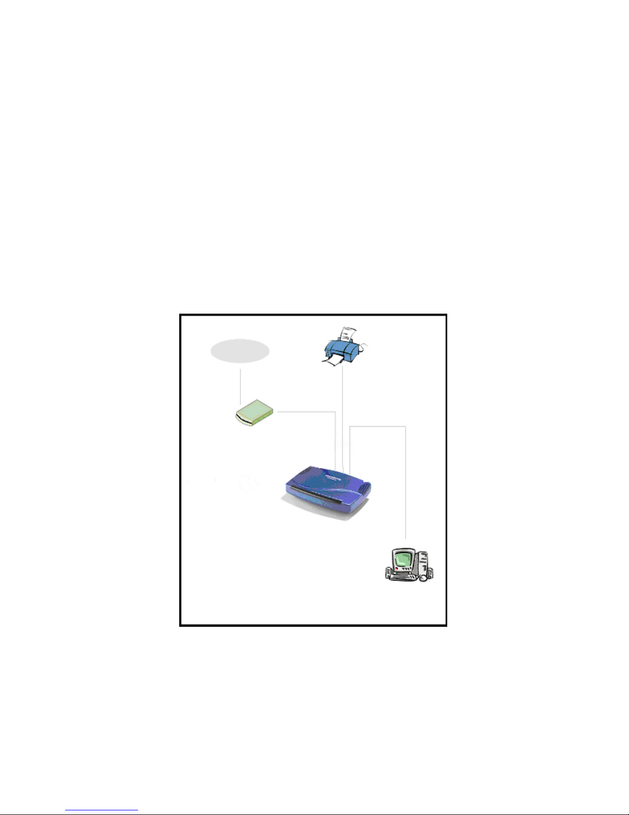
The Diagram Showing the Ways of Installing the GN-BR402
Printer
Internet
Cable/ADSL
Modem
PC
Page 5

3
2-3 Connection for Ethernet User
Step 1. Please prepare an Ethernet cable (RJ- 45) first.
Step 2. Connect the Ethernet cable to the WAN port of the GN-BR402.
Step 3. Connect an end of the network cable to the ADSL/Cable Modem of the Ethernet
connection port.
Step 4. Connect any port of the area network LAN1, 2, 3, & 4 of the GN-BR402 to your PC.
Step 5. Connect the adapter to the power connection slot of the GN-BR402.
Step 6. Insert the adapter to the power socket.
Please check if the light of the WAN port of the GN-BR402 is lit. If not, try to use
the cross over (RJ- 45) Ethernet cable that comes with this product.
Step 7. The connection procedure is completed.
2-4 Connection for USB Port User (If you use USB connection, please refer
to this section.)
Please repeat Steps 1~3 of Section 2-3.
Step 4. Connect the USB transmission cable to the USB port of the GN-BR402 and the USB port
at the PC end.
Step 5. Please install the USB driver program by the CD that comes with the GN-BR402.
(Please refer to Appendix B for the installation of the USB driver program).
Page 6

4
3. Configuration
3-1 Preparation
Generally speaking, using the GN-BR402 for Internet connection needs the ADSL or Cable service.
We assume that you have already obtained the ADSL/Cable service from the local telephone
company or the ISP Company, and get the related connection data ready.
Such data include:
a. IP address provided by ISP
b. Subnet mask
c. Default gateway IP address
d. Domain Name System (DNS) Server IP address
- The ISP Company provides the above data.
3-2 Setup at Your PC End
An easy-to-use web page setup interface is designed on the GN-BR402, and the user can perform
the setup by the browser. The Gigabyte GN-BR402 Broadband Router presets the IP address as
“192.168.1.254”, and preset as a DHCP server Please follow the step below to perform the setup
under the TCP/IP network environment. Please confirm the TCP/IP communication protocol is
installed in your computer (Windows 95/98/Me/NT). If you have not installed the TCP/IP
communication protocol, please install it now, and then select your operating system for the setup.
For Windows 2000, please jump to 3-2-1.
For Windows 95/98/Me, please jump to 3-2-2.
For Windows XP, please jump to 3-2-3.
Page 7
5
3-2-1 The Settings Under Windows2000
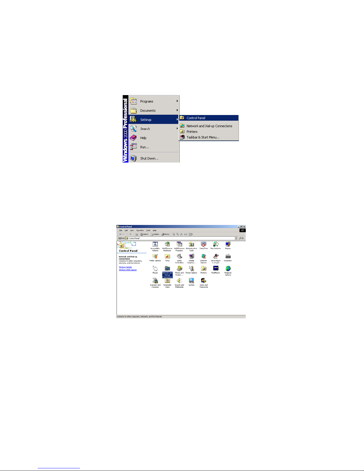
Step 1. Click “Start” in the desktop of the Windows to select “Settings”, and then click “Control
Panel”.
Step 2. Double click the “Network and Dial-up Connections”.
Page 8
6
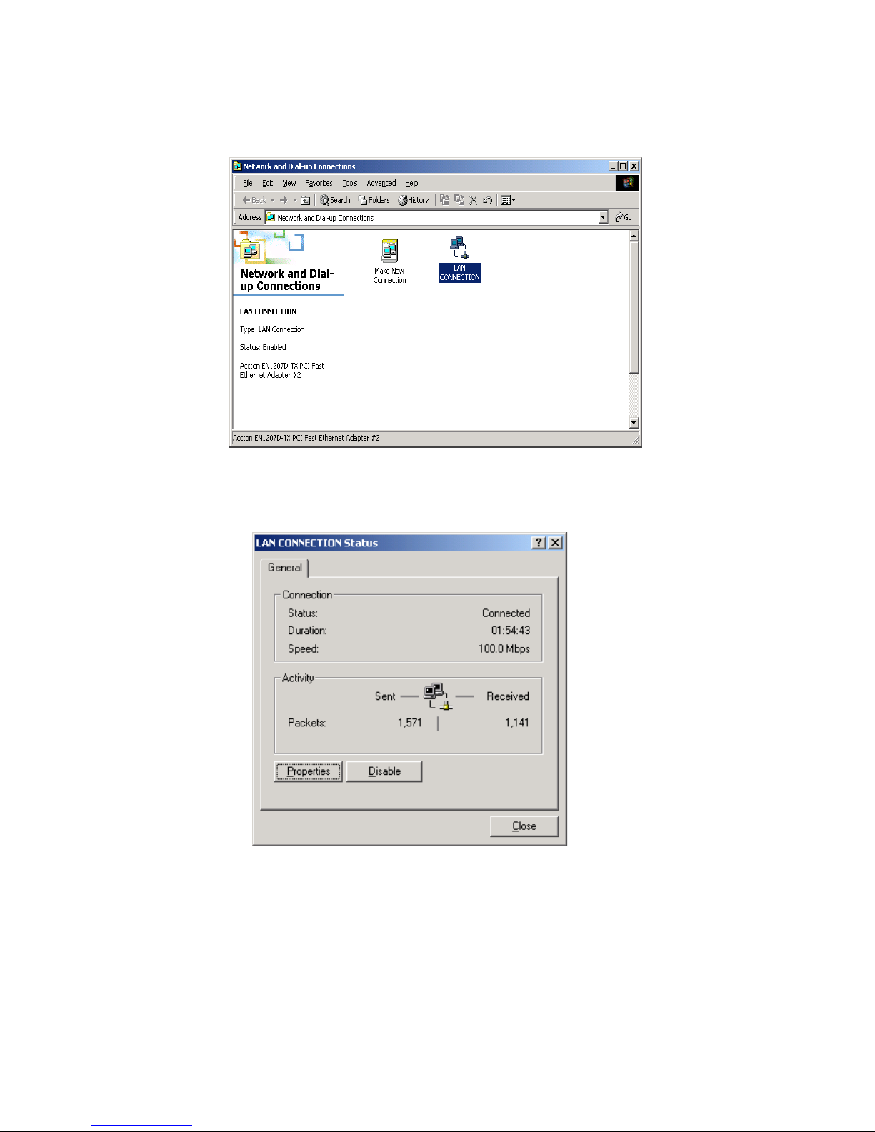
Step 3. Double click the “LAN CONNECTION”.
Step 4. Click “Properties” in the box under LAN CONNECTION Status.
Page 9
7
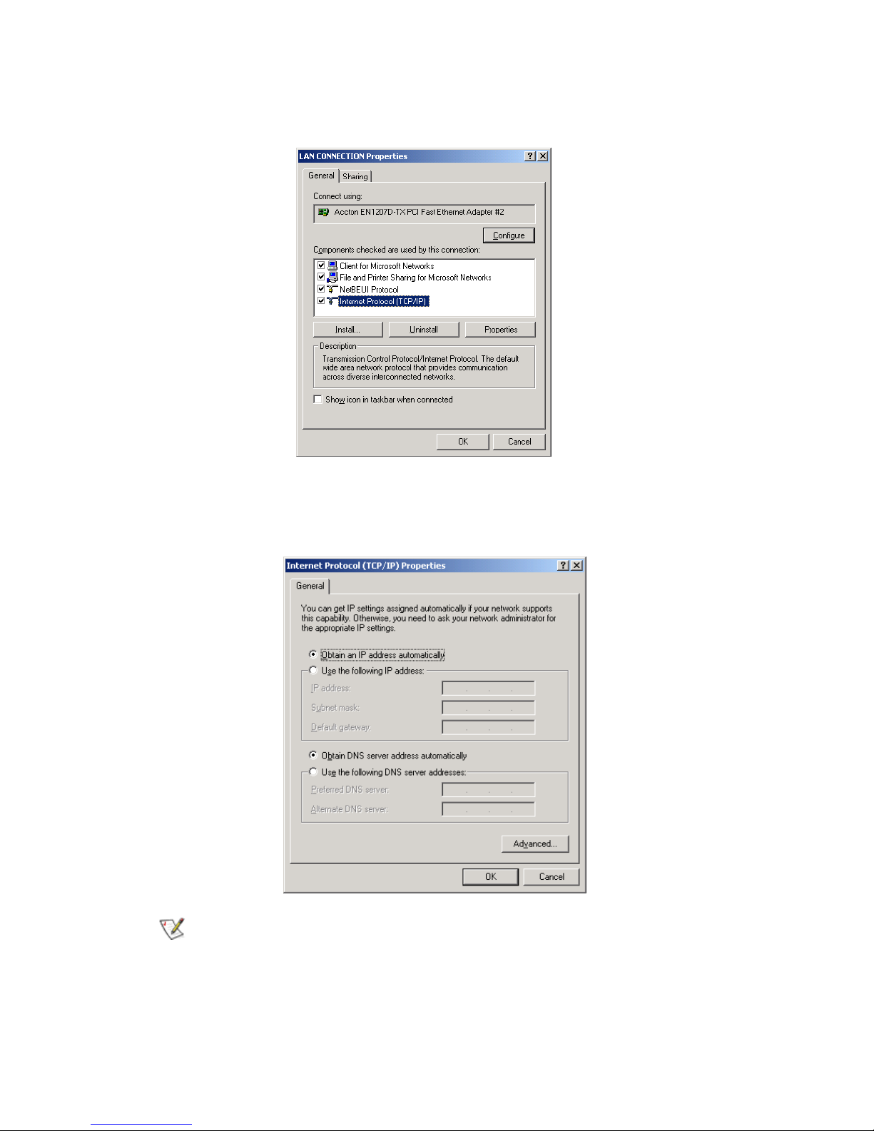
Step 5. Double click “Internet Protocol (TCP/IP)”.
Step 6. Please select “Obtain an IP address automatically” and “Obtain DNS server address
automatically”, and then enter “OK”.
Now, the computer will obtain an IP address automatically from the GN-BR402 then
you can go to Step11 directly. If you would like to obtain an IP address manually, please
refer to Step7~Step10.
Page 10
8
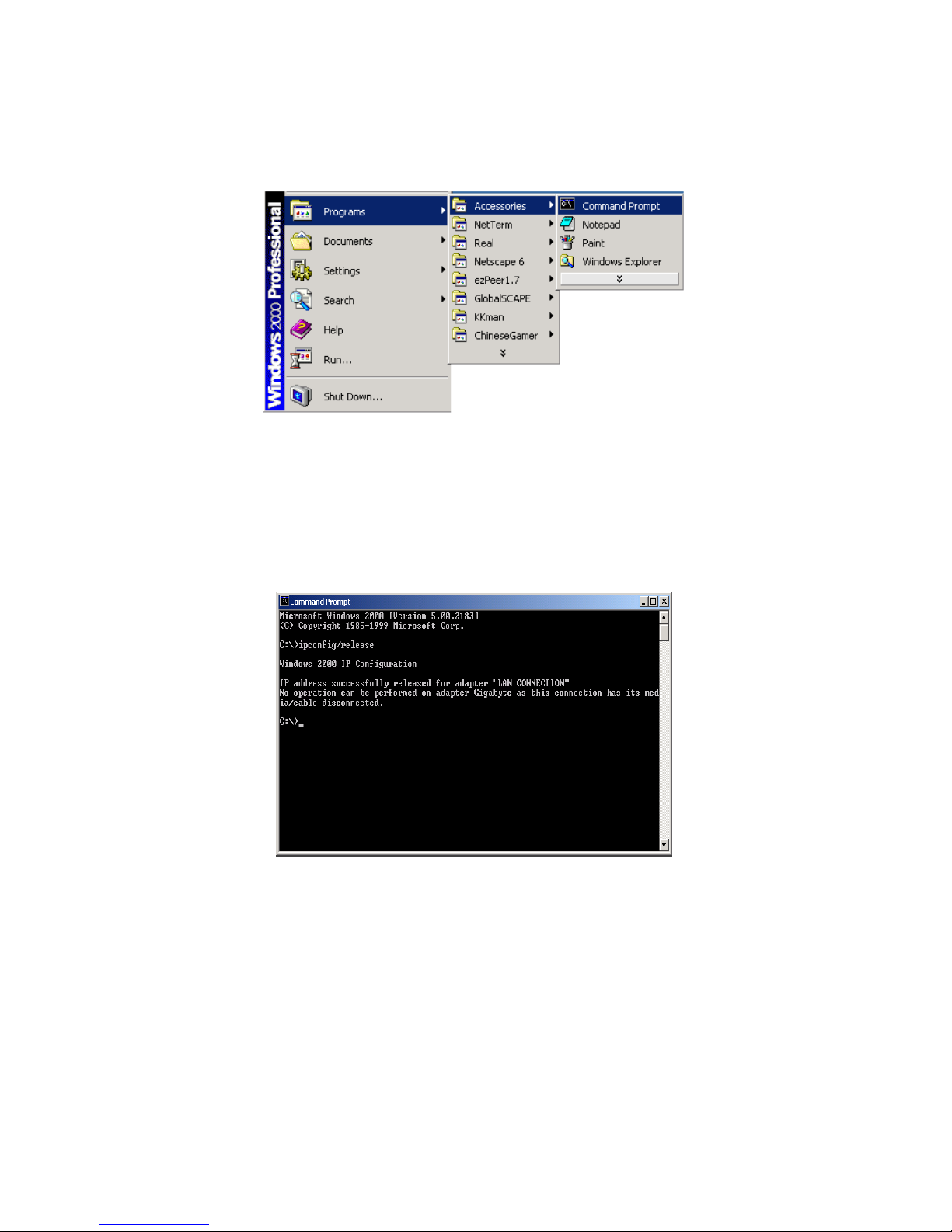
Step 7. Click “Start” at the desktop of the Windows, and then “Program”, “Accessories”, and
“Command Prompt” in sequence.
Step 8. Key in the command “ipconfig /release” in DOS mode, and then enter.
Page 11
9
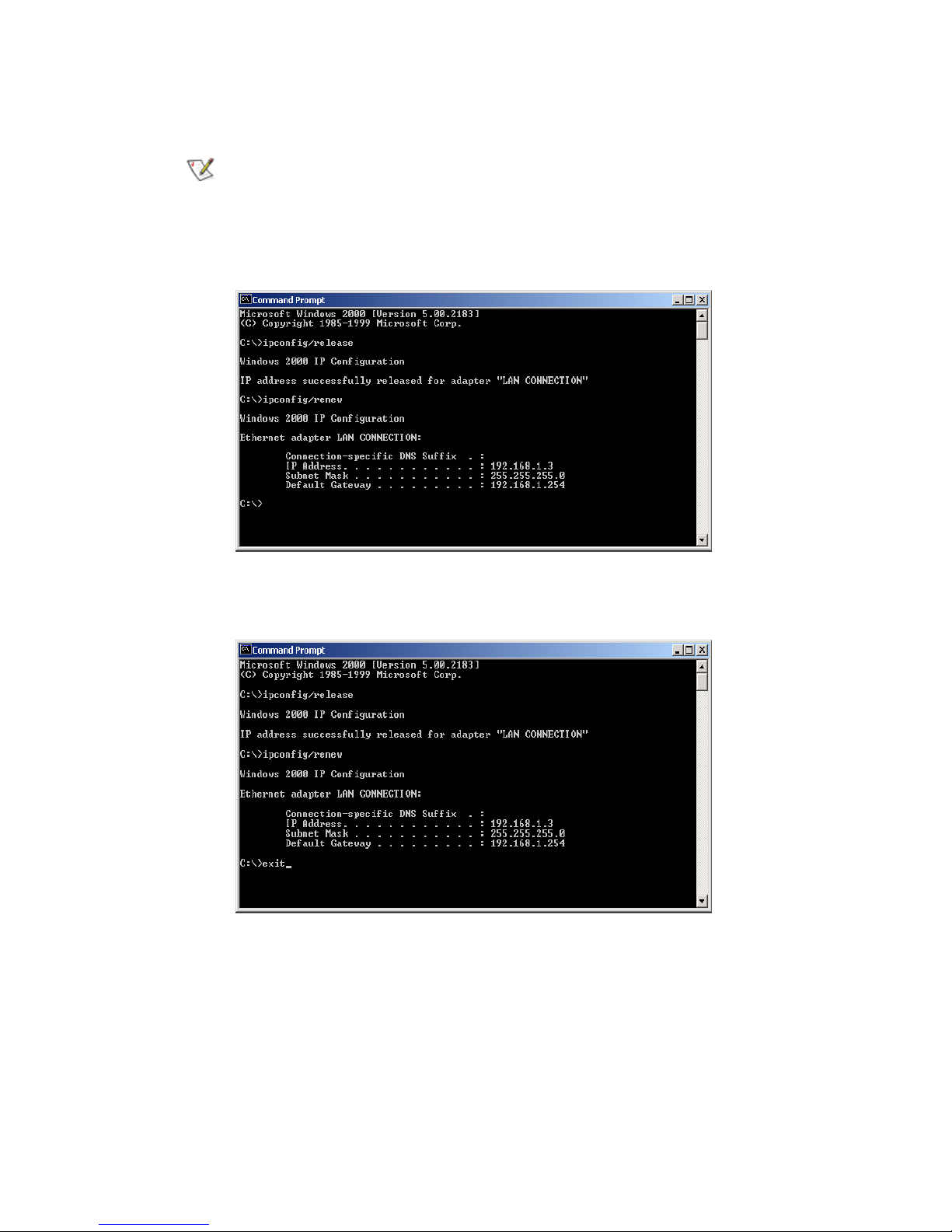
Step 9. Key in the command “ipconfig/renew”, and then enter.
If the IP address of the GN-BR402 is 192.168.1.254, the IP address of your computer
must be 192.168.1.X (where “X” is a number between 1 and 253. Each computer on
your network must have a different IP address within that range where “X” represents
a number between 1 and 253.) The default gateway must be 192.168.1.254.
Step 10. Key in “exit”, and then enter.
Page 12
10
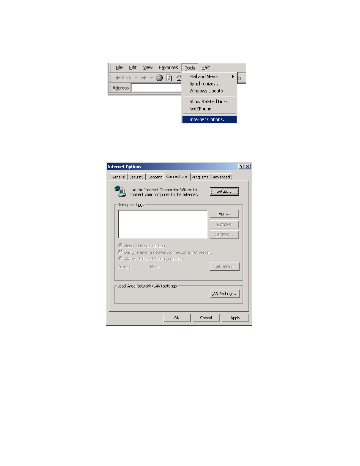
Step11. In your “IE Browser” select “Internet Options” under “Tools”.
Step 12. In this dialogue box, please click “Connections” in the “LAN Settings”.
Page 13
11
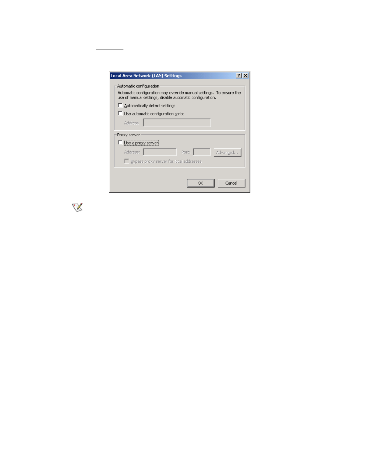
Step 13. Please DO NOT tick all of the selection boxes. Press “OK” after finishing with the
setup, and refer to Section 3-3 for setup of broadband router.
If your ISP Company has a designated Proxy setting, key in the setting after you
complete the GN-BR402 configuration. Please jump to Section 3-3 to
setup broadband router.
Page 14
12
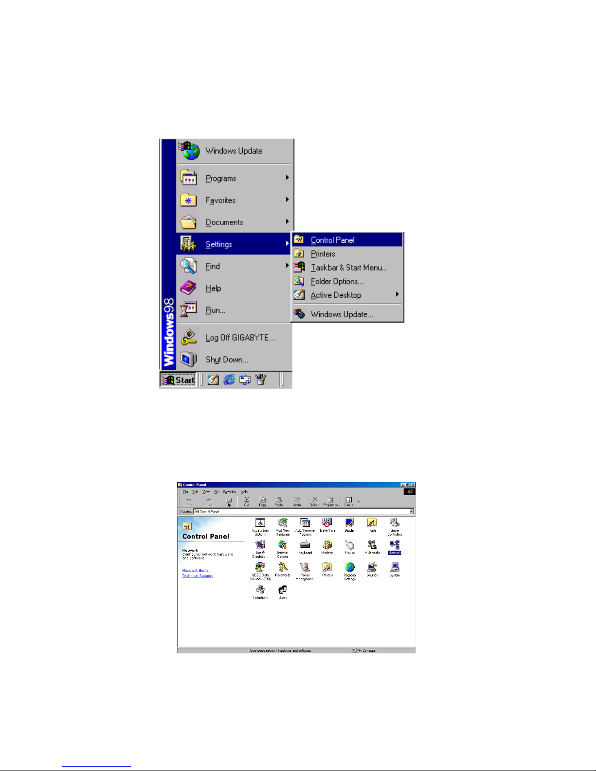
3-2-2 Setup Under the Windows 95/98/Me
Step 1. Click “Start” at the desktop of the Windows, and select “Settings”, and then the “Control
Panel”.
Step 2. Double click “Network”.
Page 15
13
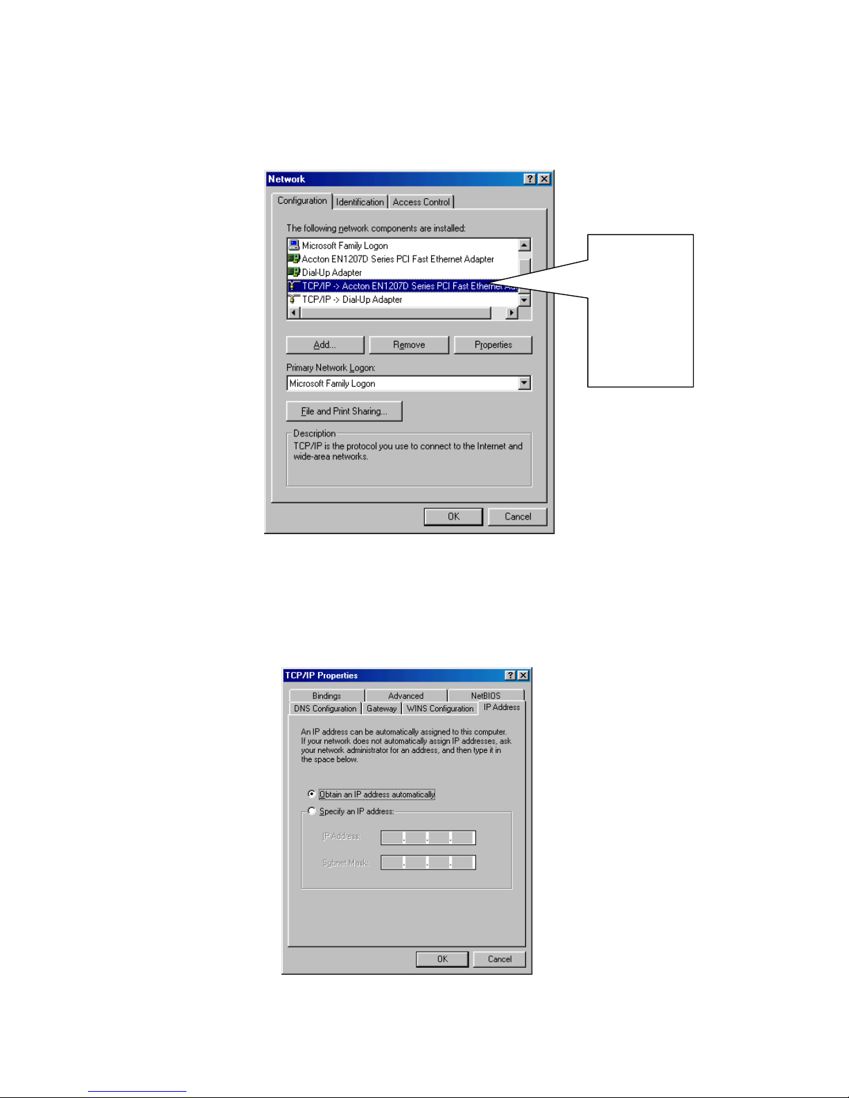
Step 3. Under Network, double click the “Configuration”, and choose your appropriate setting
“TCP/IP -> and your network card” below.
Step 4. Select “IP Address” tab and choose “Obtain an IP address automatically”, and then click
“Gateway” tab.
Please
choose the
TCP/IP and
the name of
your network
card.
Page 16
14
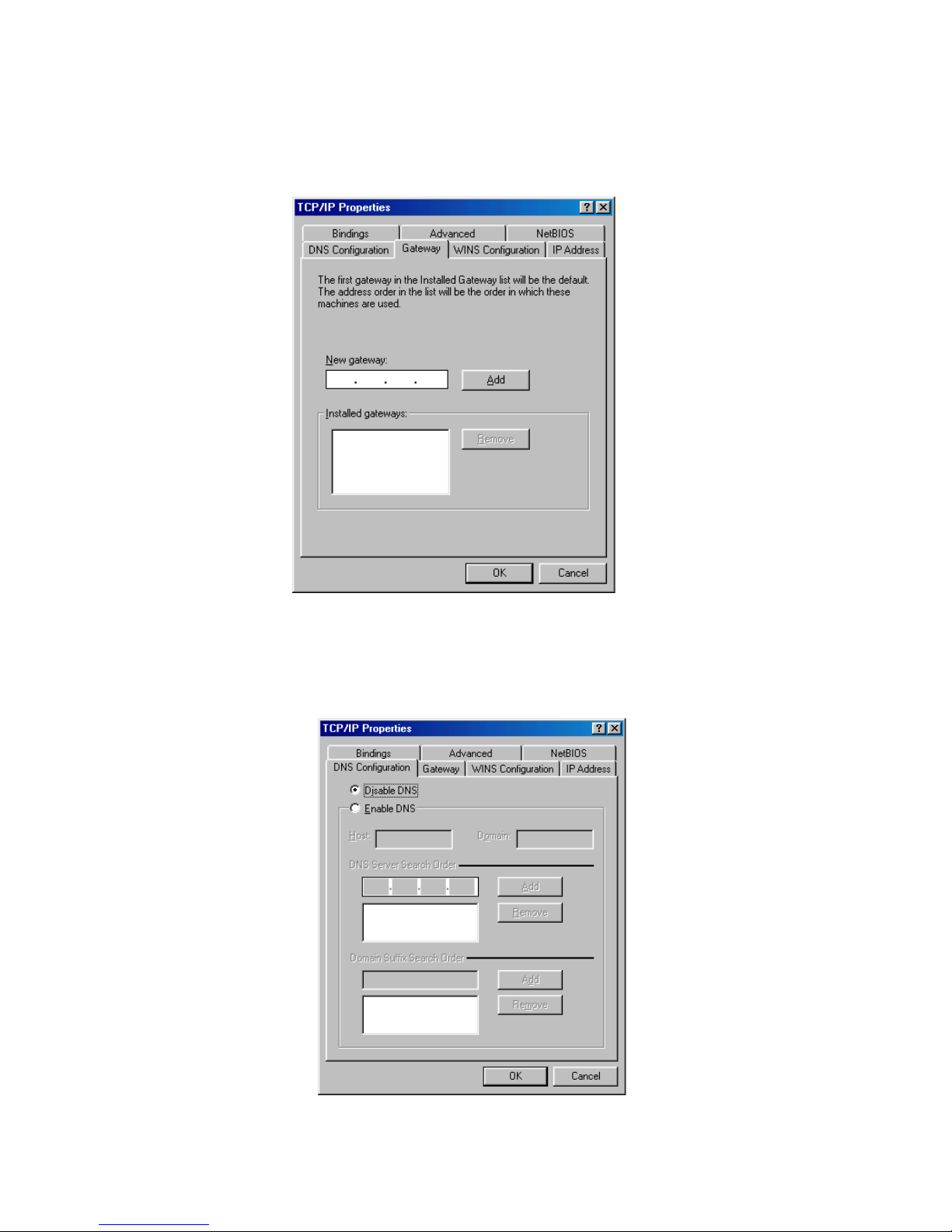
Step 5. In the window of “Gateway”, please clear all installed gateways and do not fill any of the
blanks, and then click “DNS Configuration” tab.
Step 6. In the window of “DNS Configuration”, please select “Disable DNS” and then press
“OK”.
Page 17
15
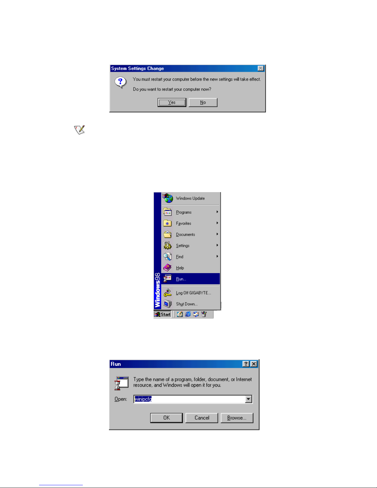
Step 7. Please press “Yes”, and reset the computer screen as follows:
After booting the computer, the computer will obtain an IP address automatically
from the GN-BR402 then you can go to Step11 directly. If you would like to obtain
an IP address manually, please refer to Step8~Step10.
Step 8. After booting the computer, please click “Start” and choose “Run”.
Step 9. Key in “winipcfg”, and press “OK”.
Page 18
16
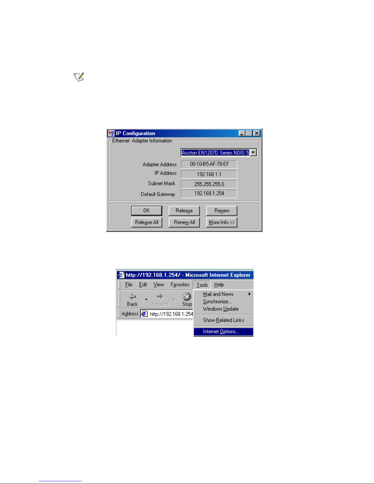
Step 10. In the pulled down menu, select your network card, press “Release All”, then press
“Renew All”, and then press “OK”.
If the IP address of the GN-BR402 is 192.168.1.254, the IP address of your computer
must be 192.168.1.X (where “X” is a number between 1 and 253. Each computer on
your network must have a different IP address within that range where “X” represents
a number between 1 and 253.) The default gateway must be 192.168.1.254.
Step11. Please select “Internet Options” under “Tools” of your IE Browser.
Page 19
17
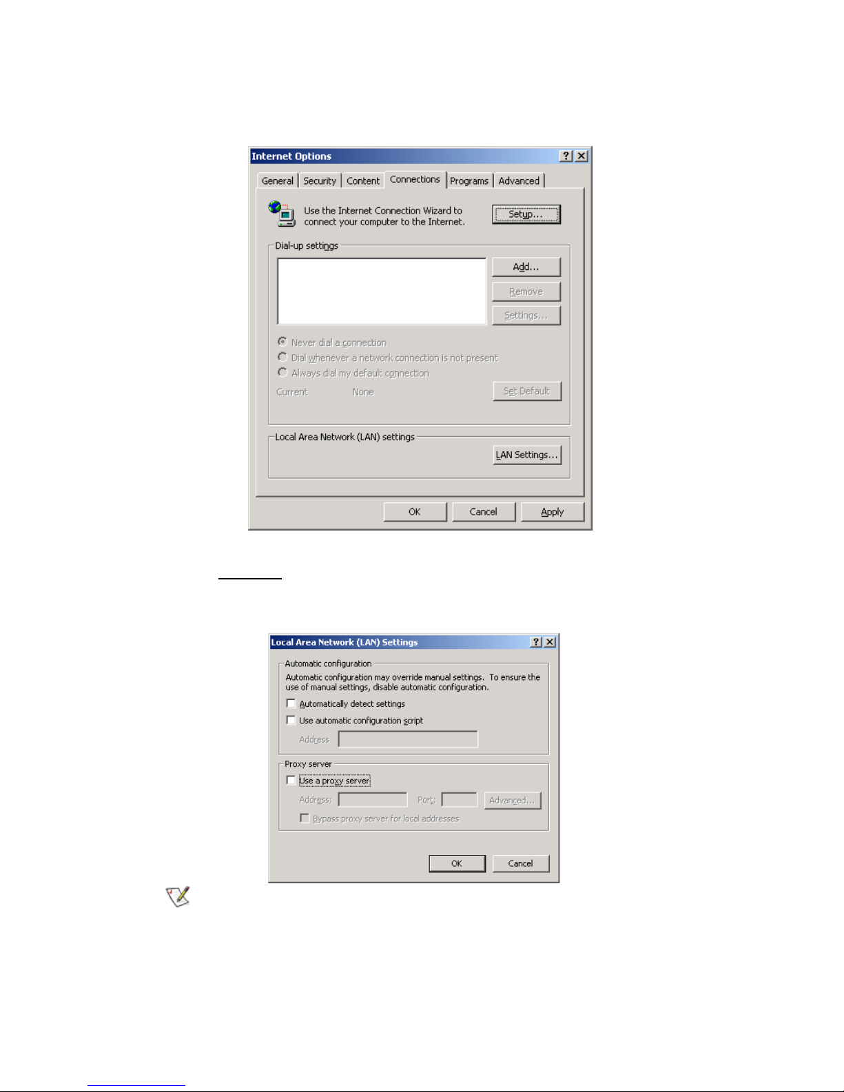
Step 12. In this dialogue box, please select “Connections” in the “LAN Settings”.
Step 13. Please DO NOT tick all of the selection boxes. Press “OK” after finishing with the
setup, and refer to Section 3-3 for setup of broadband router.
If your ISP Company has a designated Proxy setting, key in the setting after you
complete the GN-BR402 configuration
Please jump to Section 3-3 to setup
broadband router.
Page 20
18
3-2-3 Setup Under Windows XP
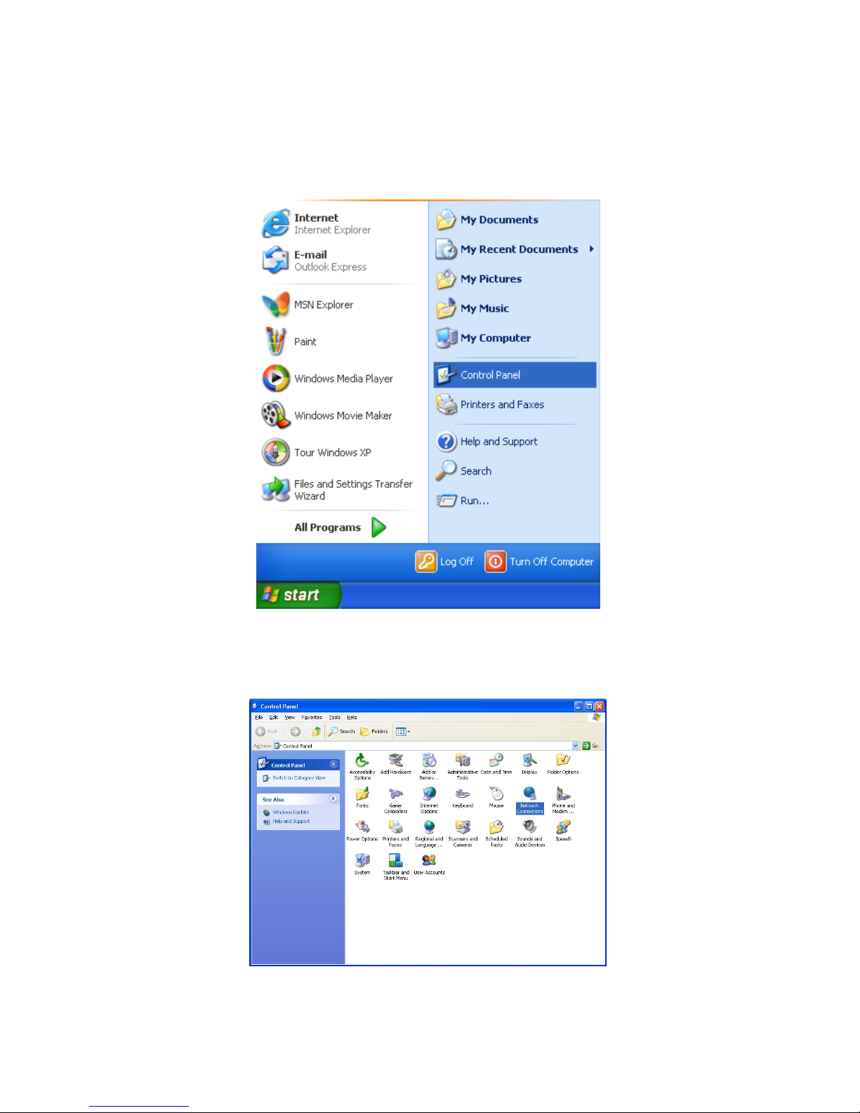
Step 1. Click the “Start” at the desktop of the Windows, and select the “Control Panel”.
Step 2. Double click the “Network and Dial-up Connections”
.
Page 21
19
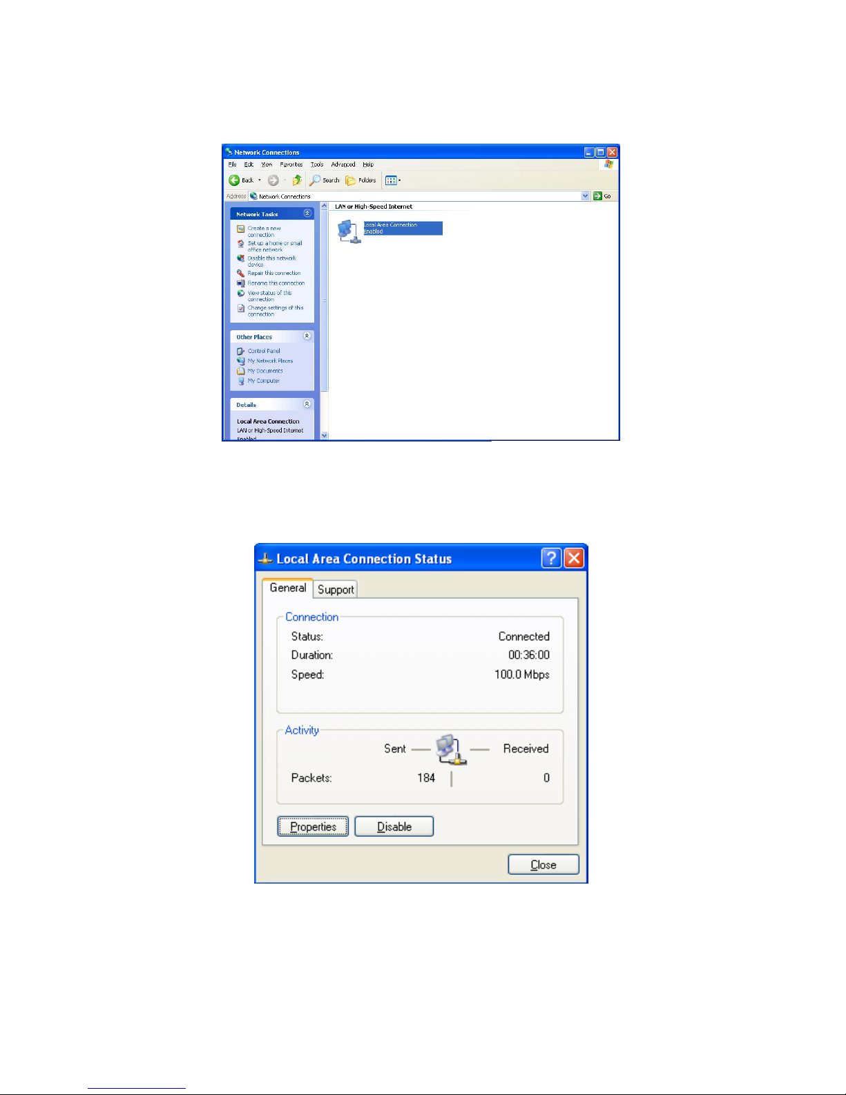
Step 3. Double click the “LAN CONNECTION”.
Step 4. Click the “Properties” in the box under LAN CONNECTION.
Page 22
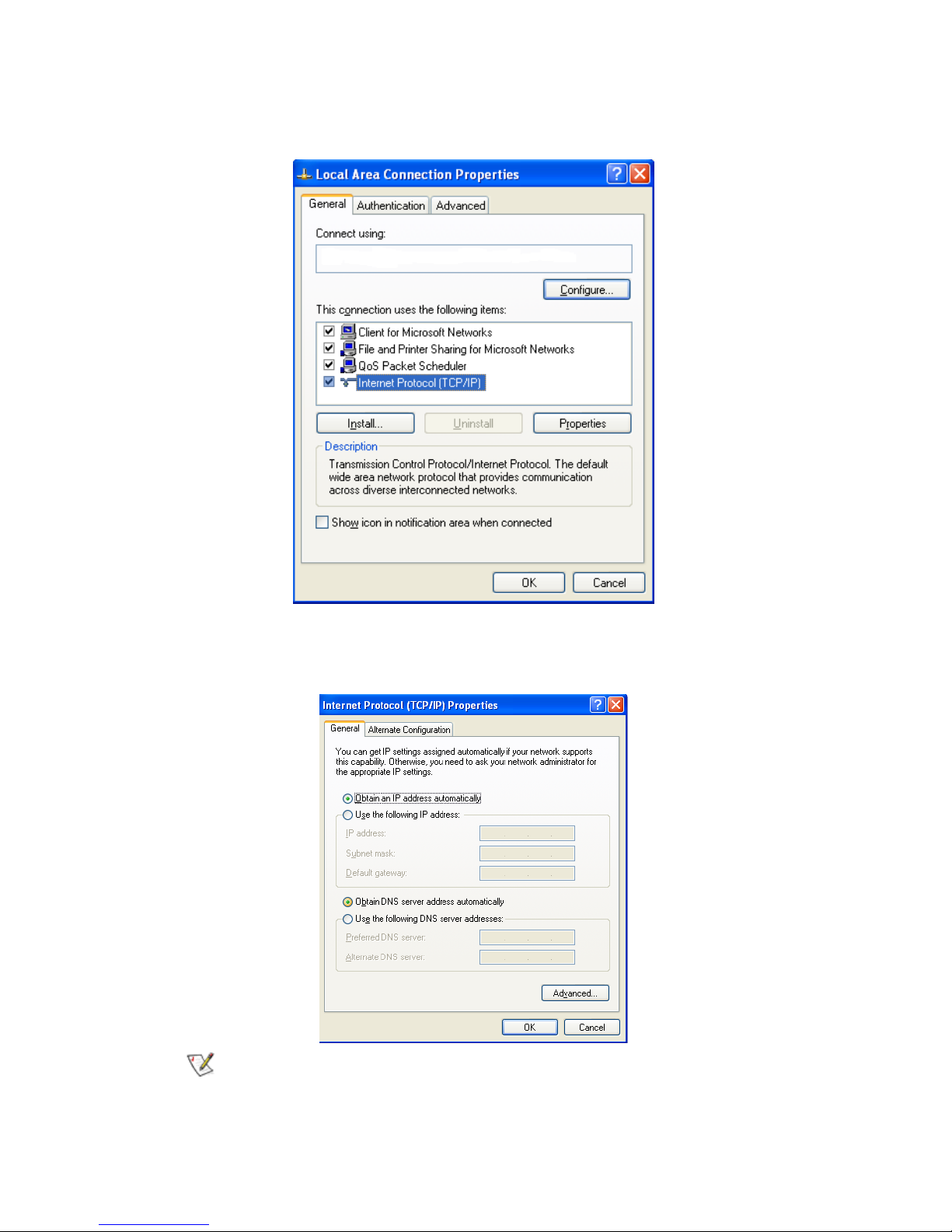
20
Step 5. Double click the “Internet Protocol(TCP/IP)”.
Step 6. Please select the “Obtain an IP address automatically” and “Obtain DNS server address
automatically”, and then press “OK”.
Now, the computer will obtain an IP address automatically from the GN-BR402 then
you can go to Step11 directly. If you would like to obtain an IP address manually,
please refer to Step7~Step10.
Page 23
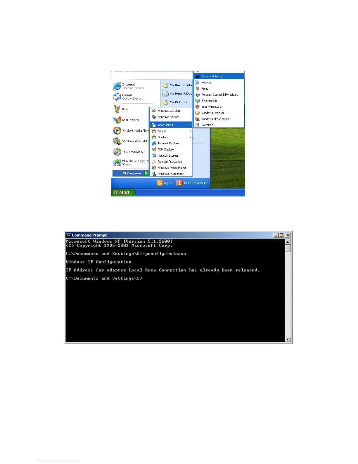
21
Step 7. Click the “Start” at the desktop of the Windows, and then the “Accessories”, and then the
“Command Prompt”.
Step 8. Input the “ipconfig /release” in the box of Command Prompt, and then enter.
Page 24
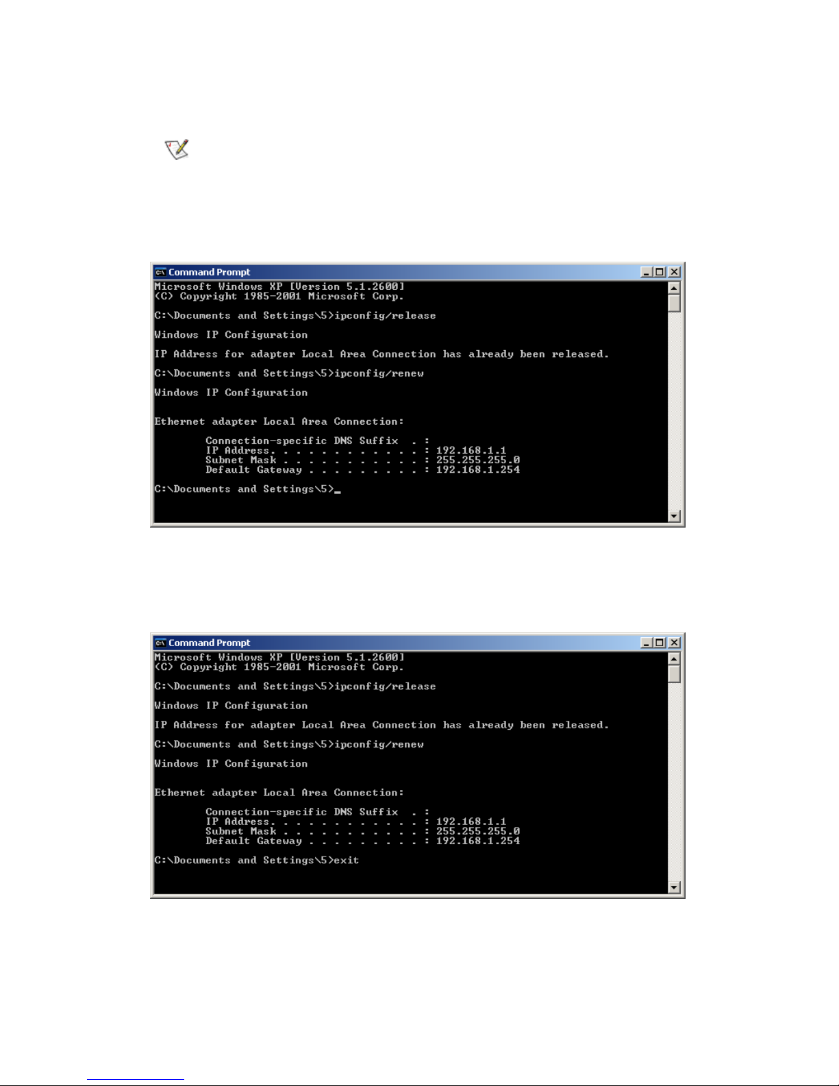
22
Step 9. Input “ipconfig/renew”, and then enter.
If the IP address of the GN-BR402 is 192.168.1.254, the IP address of your computer
must be 192.168.1.X (where “X” is a number between 1 and 253. Each computer on
your network must have a different IP address within that range where “X” represents
a number between 1 and 253.) The default gateway must be 192.168.1.254.
Step 10. Input “exit”, and then press enter.
Page 25
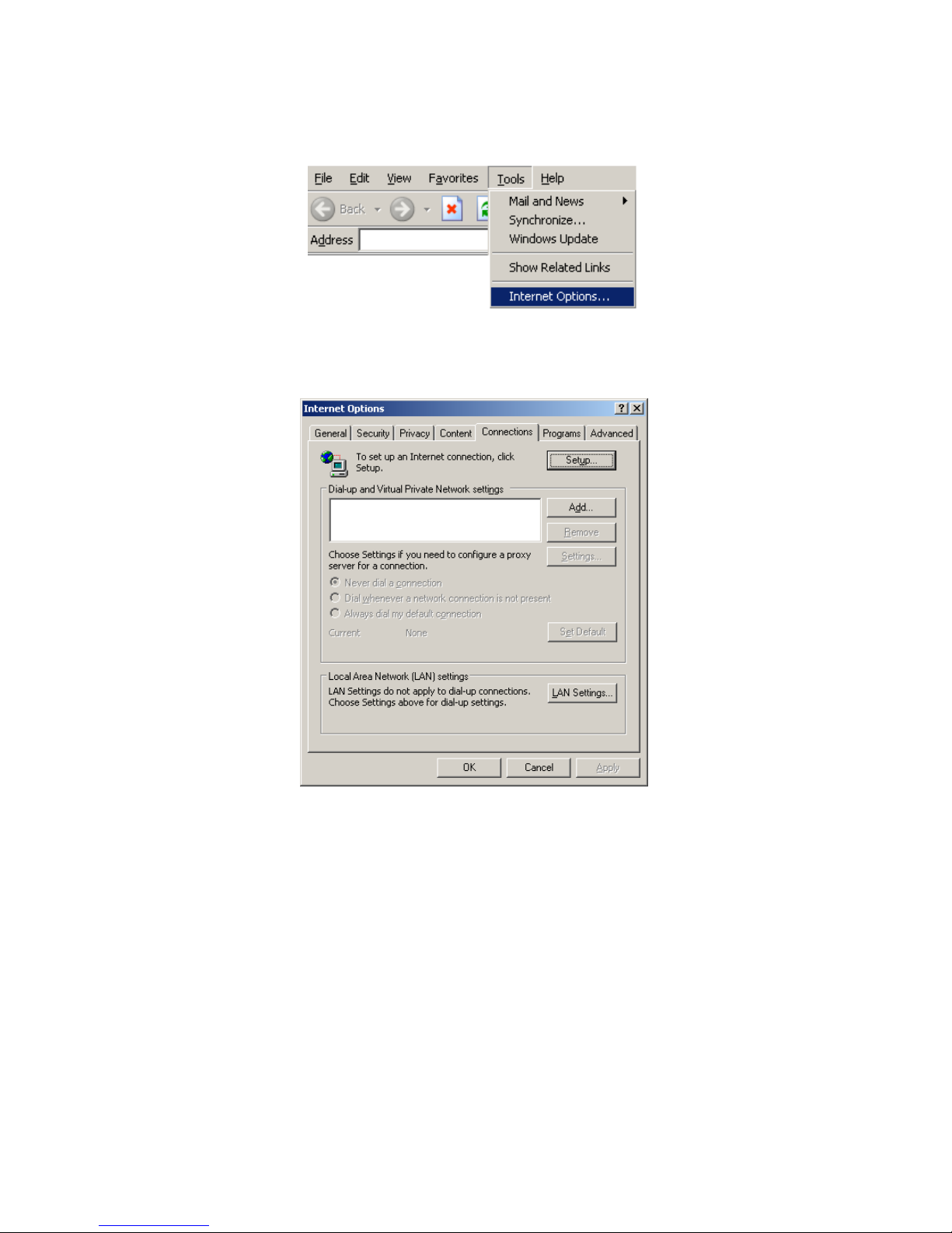
23
Step 11. Please select “Internet Options” under “Tools” of your IE Browser.
Step 12. In this dialogue box, please select “Connections” in the “LAN Settings”.
Page 26
24
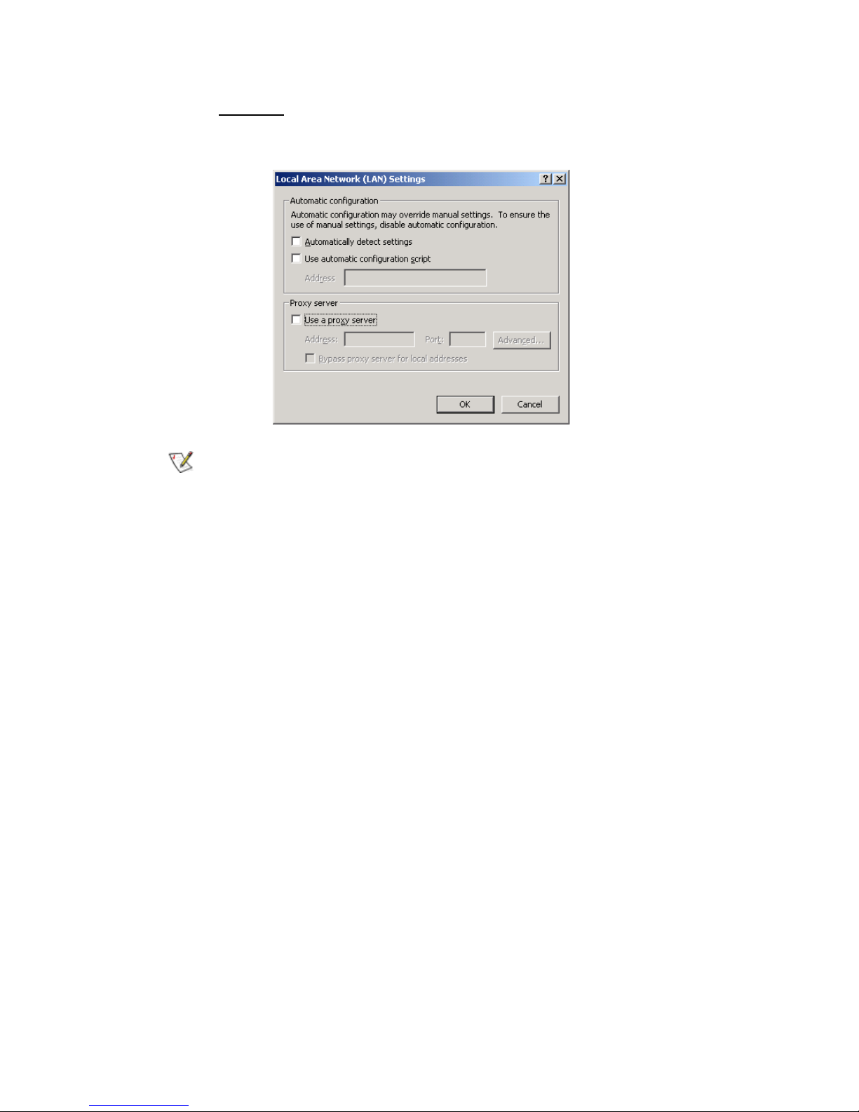
Step13. Please DO NOT tick all of the selection boxes. Press “OK” after finishing with the
setup.
If your ISP Company has a designated Proxy setting, key in the setting after you
complete the GN-BR402 configuration Please jump to Section 3-3 to setup
broadband router.
Page 27
25
3-3 Setup for Broadband Router
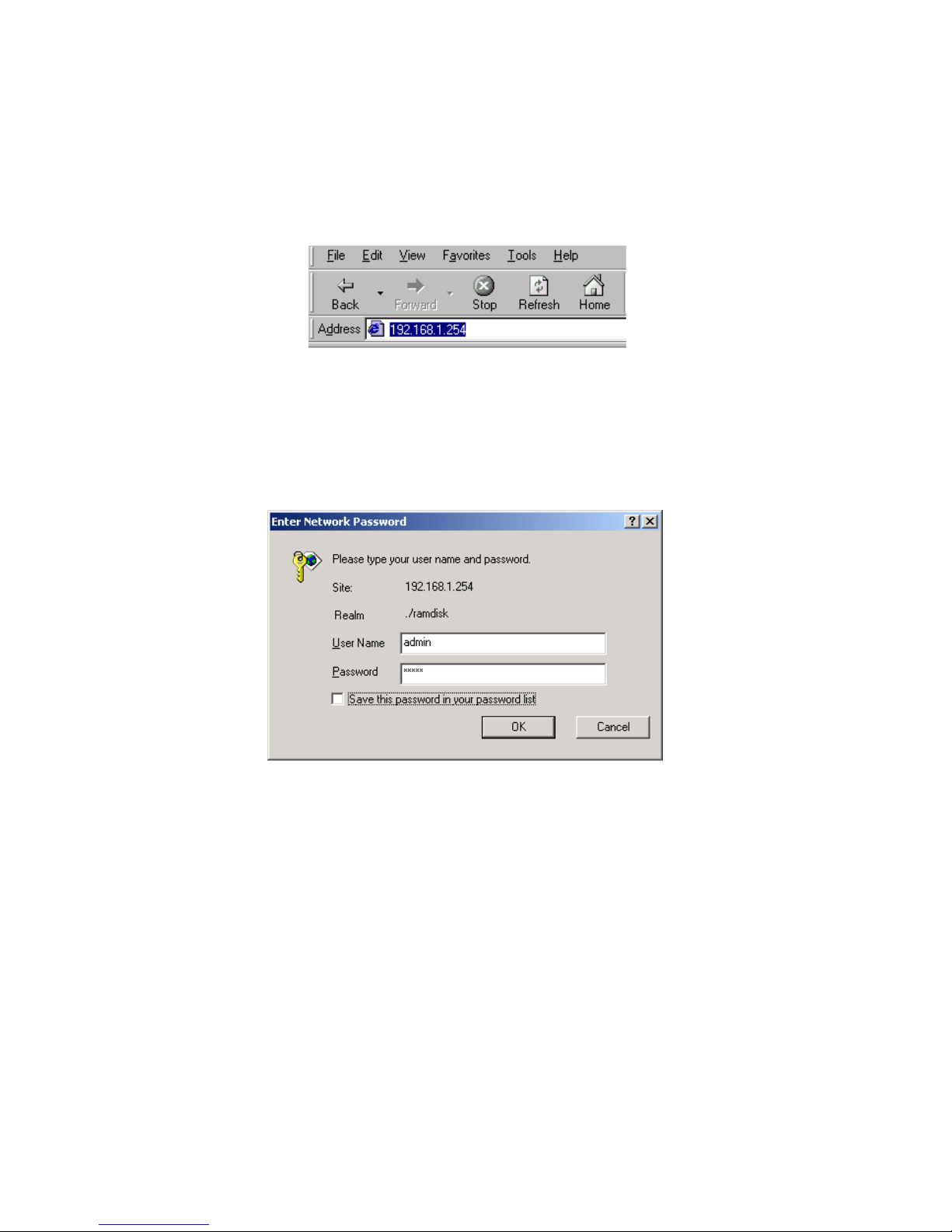
Step 1. Key in the preset IP address“192.168.1.254” in the address column in the browser, and
then press enter.
Step 2. The dialogue box will appear as shown in the following diagram, and key in the default
user name “admin” for the wideband network GN-BR402 and the default password
“admin”, and then press “OK”:
Page 28
26
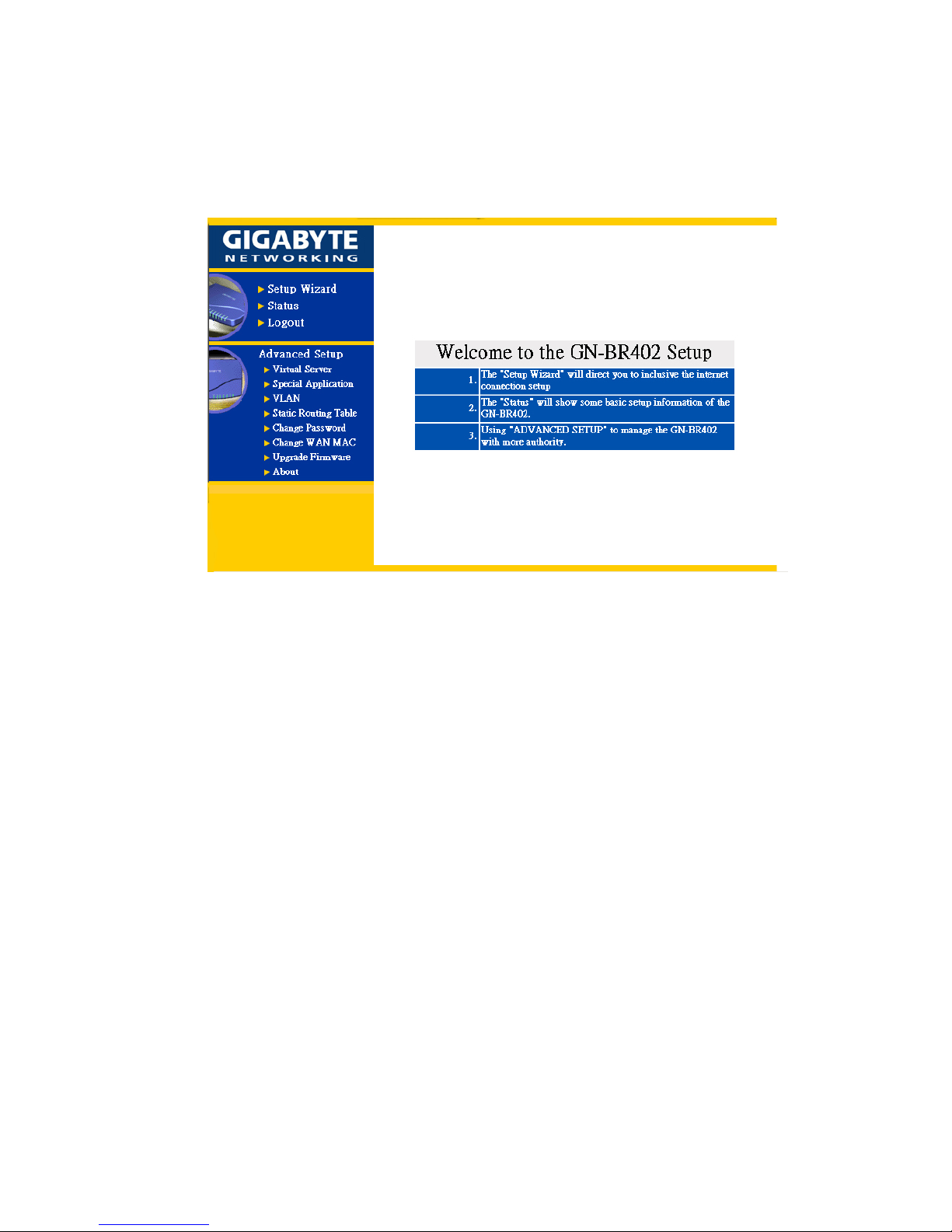
Step 3. The homepage of the GN-BR402 will appear as shown below, and click the “Setup
Wizard” on the screen, and such “Setup Wizard” will guide you to complete the
necessary steps for the setup on screen as follows.
Page 29
27
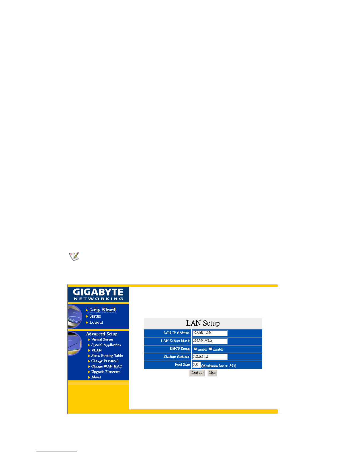
Step 4. “LAN Setup” is shown in the diagram. Each setup item of the local area network is default
setting, and is not necessary to make change to it for normal operation. Please input the
settings on your own if change is needed.
DHCP Setup:
- ”enable” indicates that the DHCP function of the GN-BR402 is initialized,
and you configure the computers on your network to “Obtain an IP address
automatically”, then when you turn your computer “On”, it will
automatically load the proper TCP/IP setting from GN-BR402. (Configure
the DHCP starting address and the DHCP allocation number on your own.)
- “disable” indicates that it will not automatically load proper TCP/IP setting
from the GN-BR402. You will have to configure all the TCP/IP setting for
your network manually. (It is not necessary to configure the DHCP starting
address and the DHCP allocation number.)
DHCP Starting Address:
When the DHCP setting is “enable”, the GN-BR402 uses this address as the
initial value to assign the IP to the PC connected to the LAN end.
For example:
The DHCP starting address is 192.168.1.1
DHCP allocation number is 50.
The IP allocable range of the DHCP is from 192.168.1.1 to 192.168.1.50.
The LAN IP address “192.168.1.254” is the default IP address of the GN-BR402.
Click “Next”, and the following screen will appear:
Page 30
28
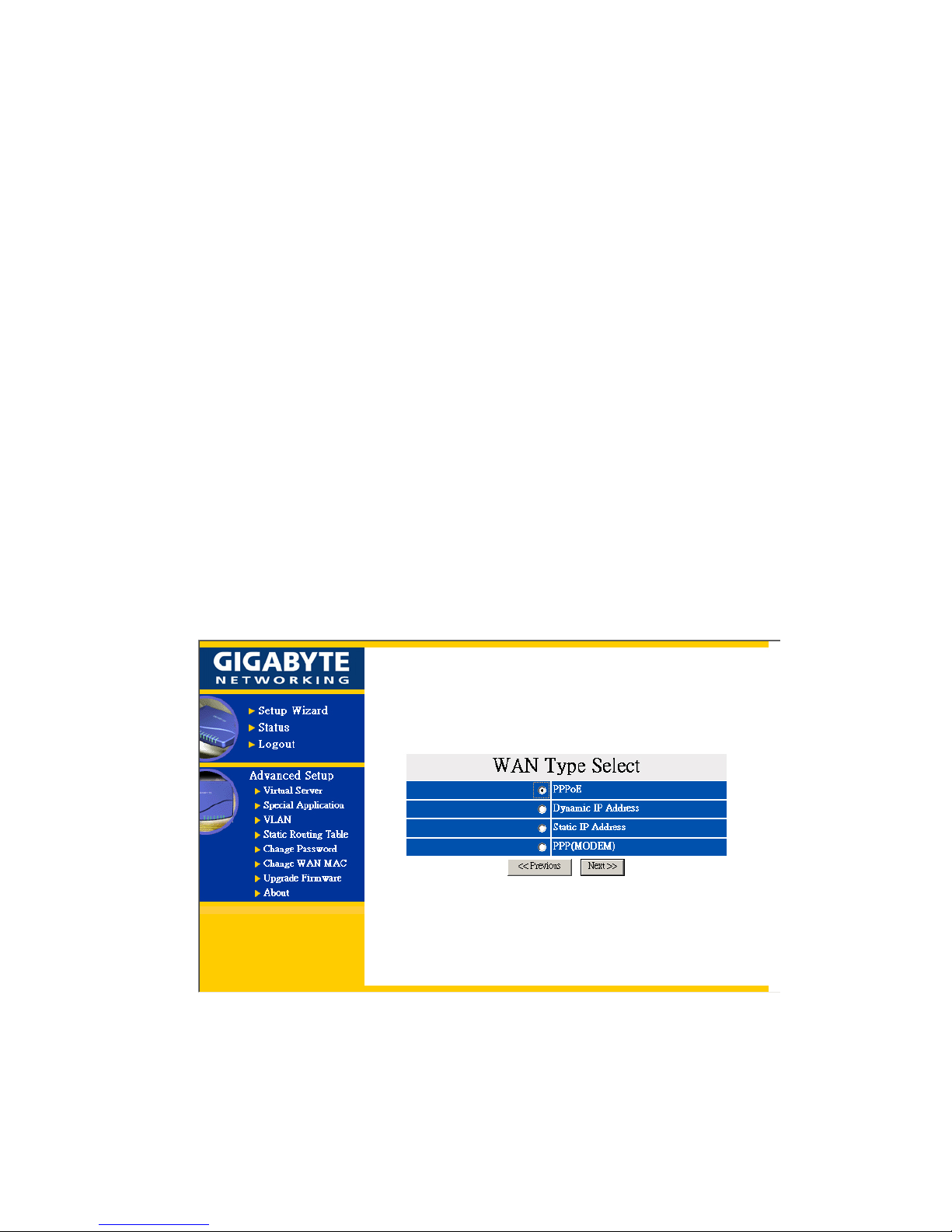
Step 5. Choose your desired wide area network mode
PPPoE: If you are using the hourly rate for the ADSL, please select this item.
Note –PPPoE Please jump to Step 6
Dynamic IP Address: If you use the wideband fixed connection of ADSL/Cable Modem,
but do not have a static IP, please select this item.
Note –Dynamic IP Please jump to Step 10
Static IP Address: If you use the wideband fixed connection of ADSL/Cable Modem,
but have a static IP, please select this item.
Note –- Static IP Please jump to Step 14
Modem: If you use the wideband fixed connection of PPP(Modem) , please select this
item.
Note –- PPP(Modem) Please jump to Step 18
After your desired wide area network mode is selected, please press “Next”.
Page 31

29
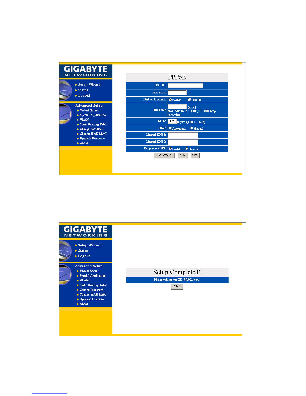
Step 6. If you select “PPPoE ” under the WAN TYPE SELECT, key in the User ID and password.
The wideband company provides the above data, and press “Finish” to go to next step.
PPPoE User ID and Password:
The “User ID” and “Password” your ISP assigned to you.
Dial on Demand:
- “Enable” : IF you are not using the Internet for a while and the
“Maximum Idle Time” set neithor 0 or 1440, and then the WAN
connection will be automaticly disconnected. When you want to use the
Internet again (You can start a IE browser and enter one URL.) then the
WAN connection will be automaticly reconnected to WAN by
GN-BR402.
- “Disable” : When the WAN connection is automatically disconnected and
you want to use the Internet again then you will have to manually
reconnect to Internet.
Maximum Idle Time:
The “Idle Time” means after this time period if you do not use the Internet
for a while, the time expired, and the WAN connection will be auto
disconnected. The on-line charge will be stopped. GN-BR402 will keep
connection always alive when the Idle Time value is “0” or “1440”.
MTU(Maximum Transmission Unit):
This defines the maximum size of the packets sent from your computer onto
the network. Any messages larger than the MTU are divided into smaller
packets before being sent. Leave this on the default value(1492) unless you
have a particular reason to change it.
DNS:
- “Automatic” : Automatically assigned from your ISP.
- “Manual” : Please key in the Manual DNS1 and Manual DNS2 IP address.
Response PING:
- “Enable” : GN-BR402 will reply the ping command from other computers
which locates on the WAN site.
-“Disable”: GN-BR402 will not reply the ping command from other
computers which locates on the WAN site.
Page 32
30
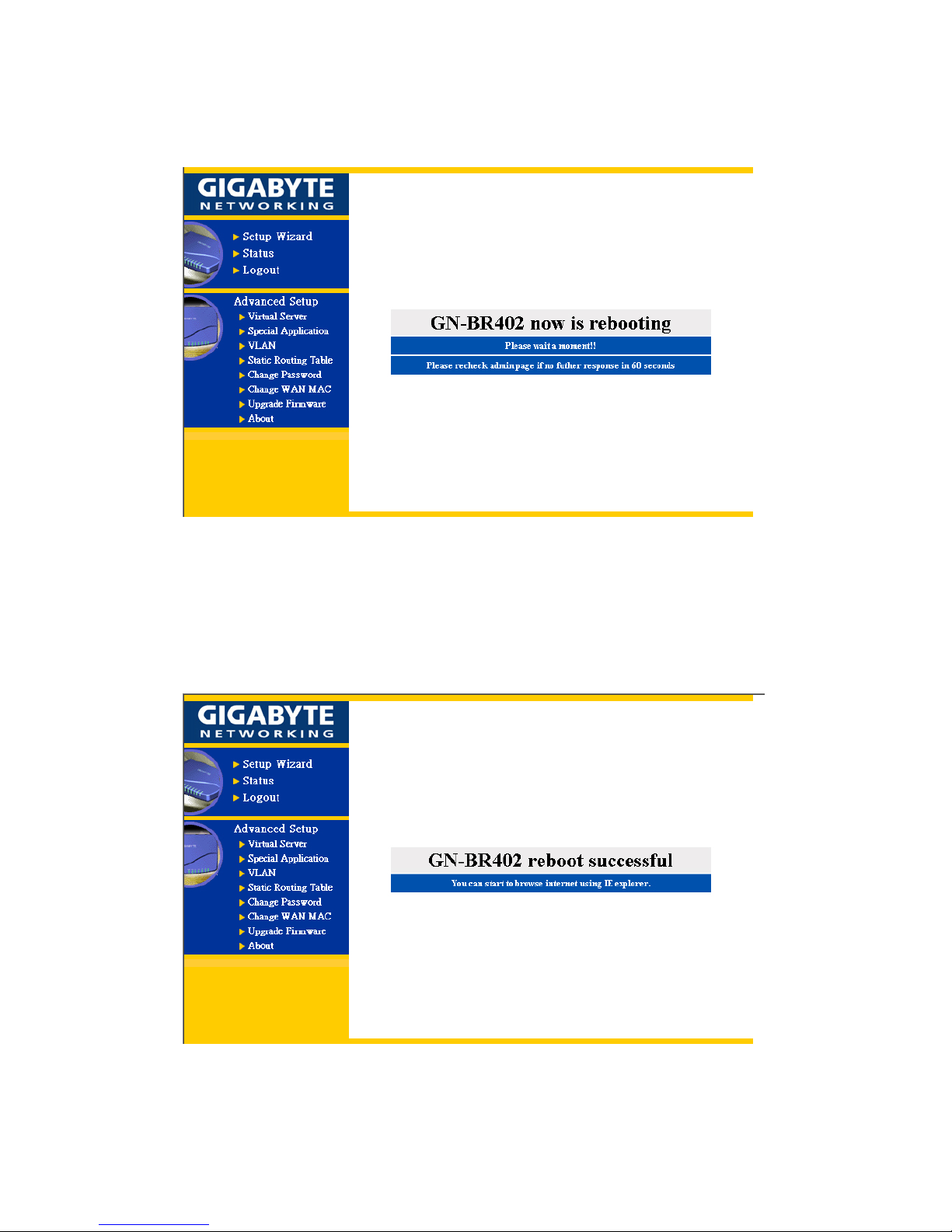
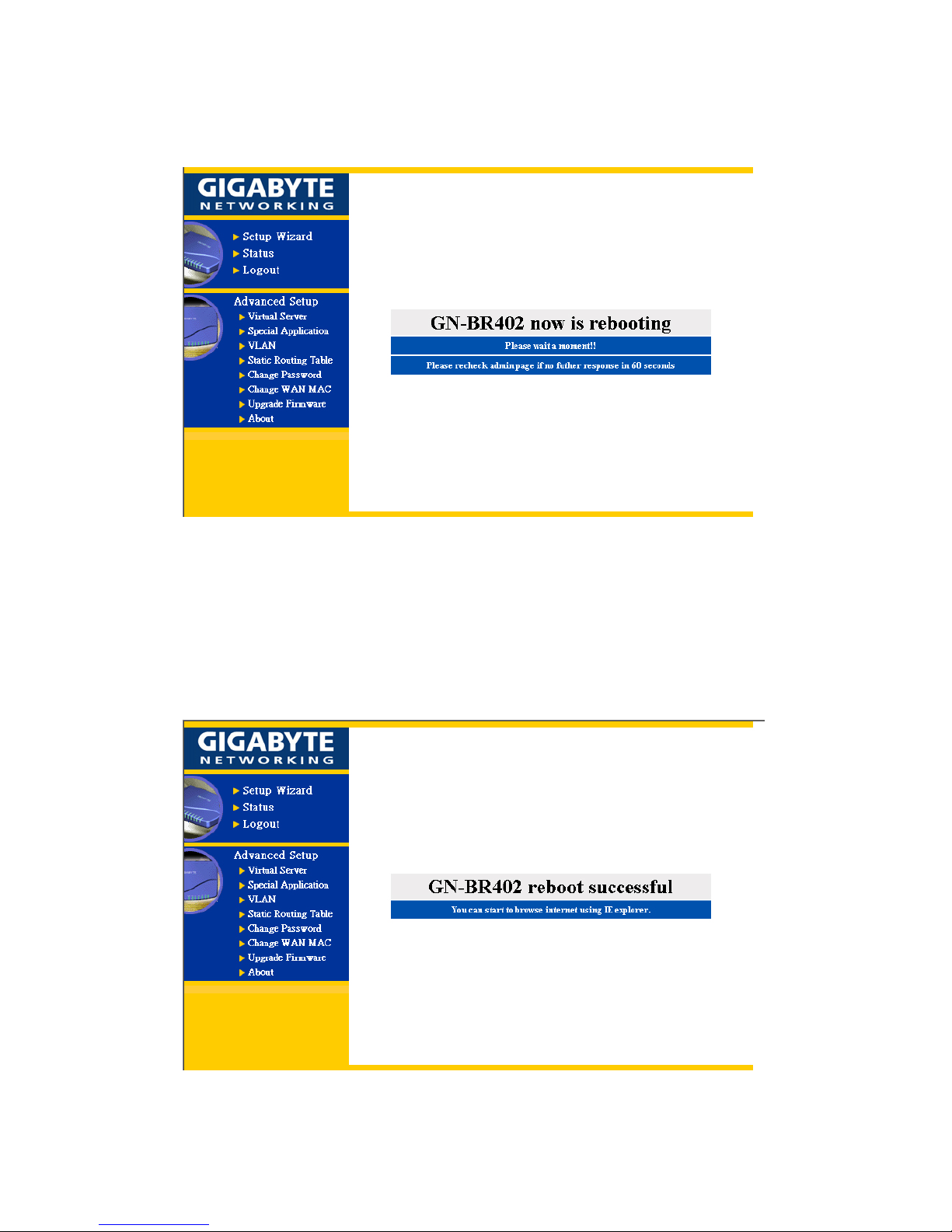
Step 7. Press “Reboot” to go to next step.
Page 33
31
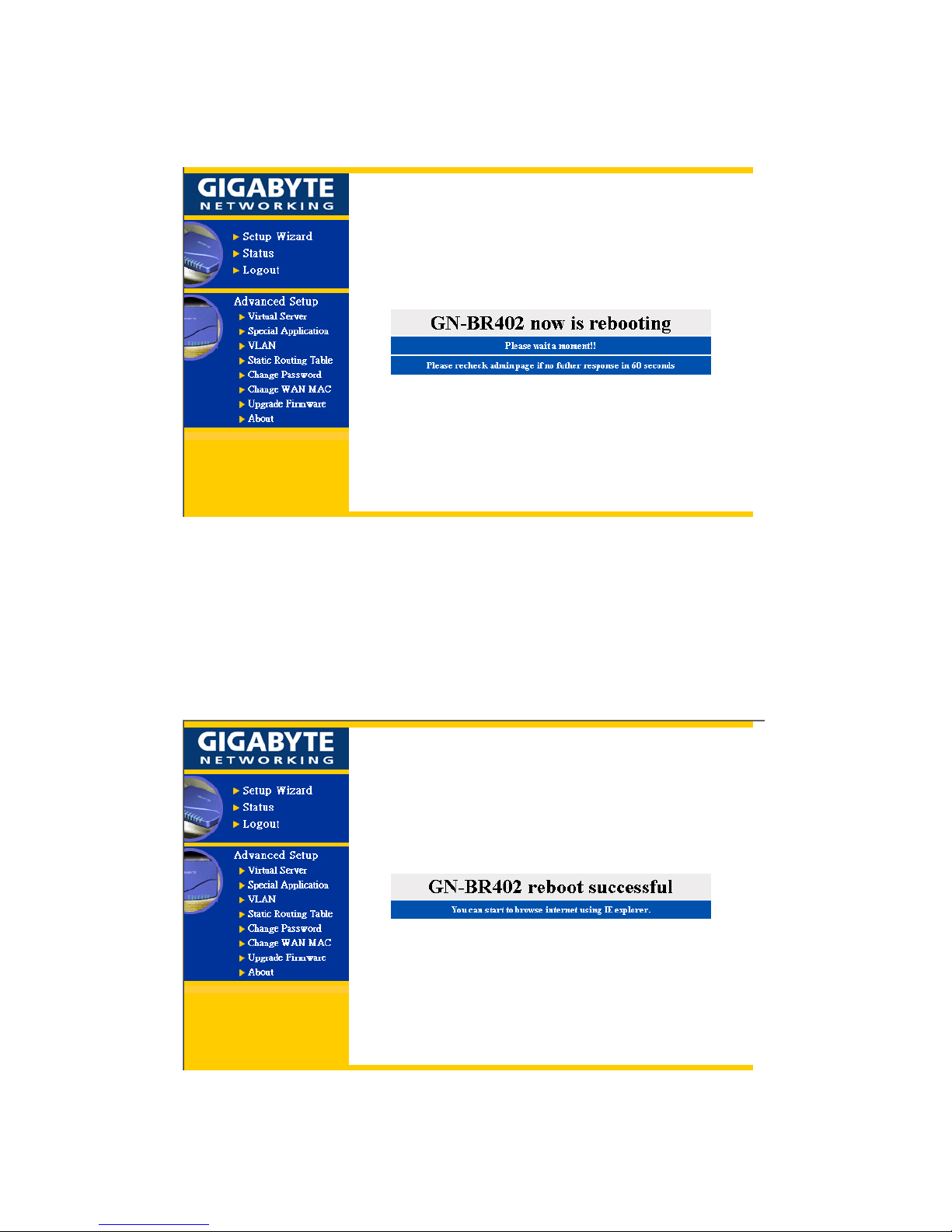
Step 8. Please wait a moment.
Step 9. The IE browser will be automatically connected to the main
menu, and your setup has completed by then. Please use your
IE connect to Internet.
If you can connect to the Internet , the setting is completed.
Page 34
32
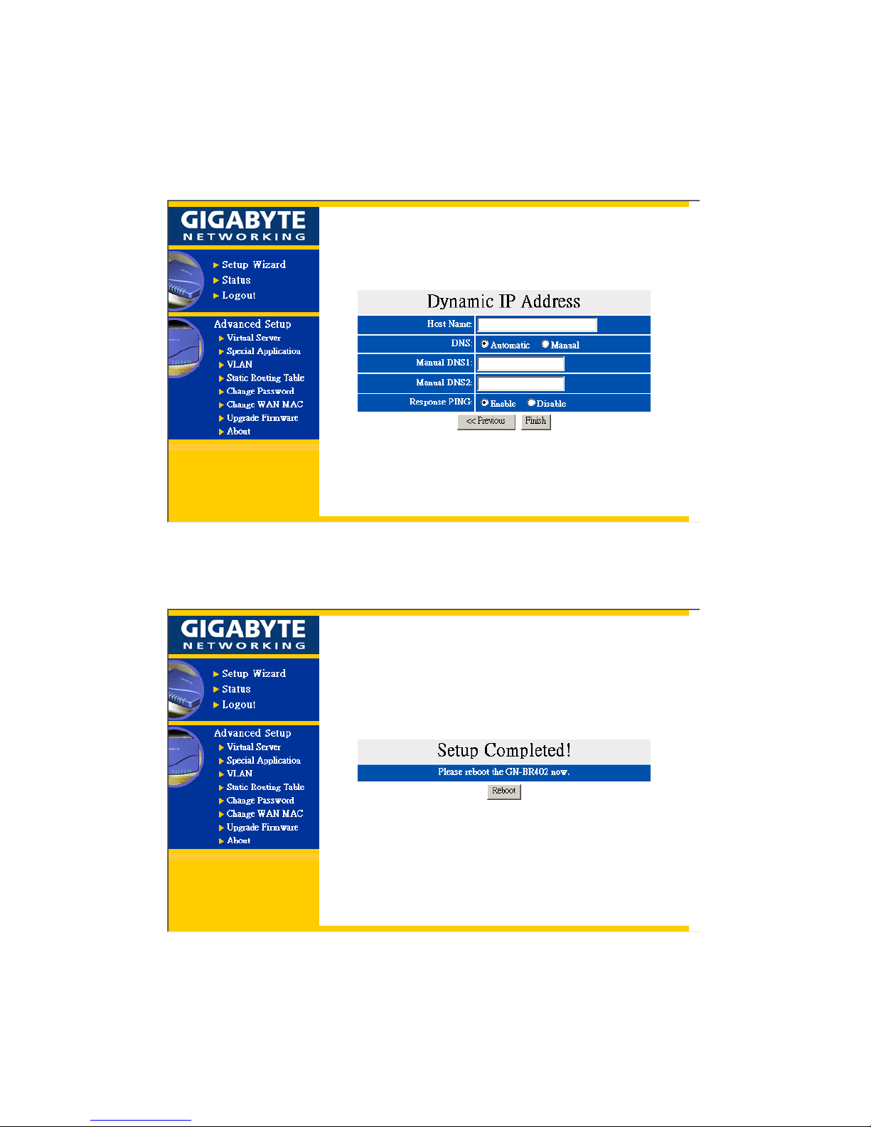
Step 10. If you select the “Dynamic IP Address” in the WAN TYPE SELECT, the following screen
will appear. First, select “Automatic” or “Manual” DNS. Please key in the Host Name and
Manual DNS IP address if you select “Manual” DNS. Press “Finish” to go to next step.
Step 11. After “Reboot” is pressed, it proceeds with the next step.
Page 35
33
Step 12. Please wait a moment.
Step 13. The IE browser will be automatically connected to the main
menu, and the setup is completed by then. Please use your IE
connect to Internet.
If you can connect to the Internet , the setting is completed.
Page 36
34
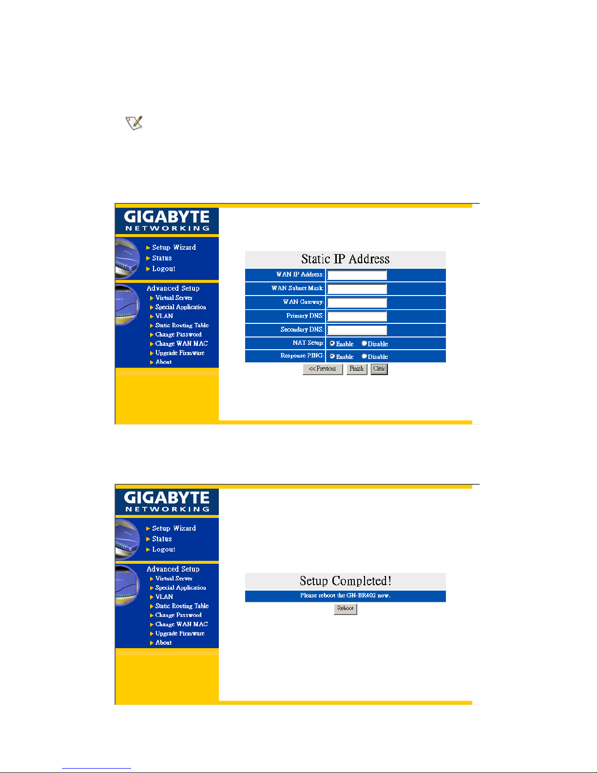
Step 14. If you select “Static IP Address” in the WAN TYPE SELECT, please key in the data
provided by the wideband company in the following fields as shown below:
a. If your wideband company gives you more than one IP address, then select one of
them to fill in the column in the following fields, and refer to Appendix A for the
use of other IP addresses.
b. Static IP Setup
Normal Users please use "NAT enable" then connect to Internet in general.
Step 15. After “Reboot” is pressed, it proceeds with the next step.
Page 37
35
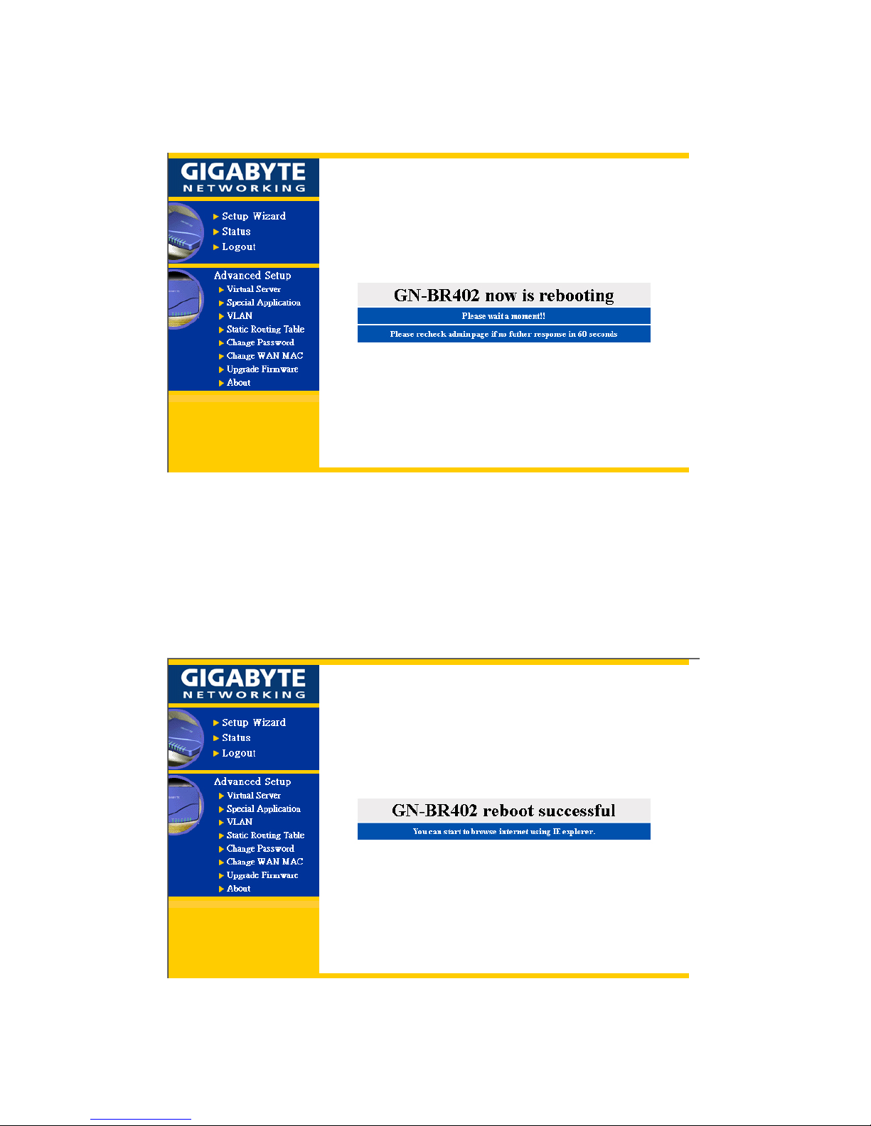
Step 16. Please wait for a moment.
Step 17. The IE browser will be automatically connected to the main
menu, and the setup at the PC end is completed by then.
Please use your IE connect to Internet.
If you can connect to the Internet , the setting is completed .
Page 38
36
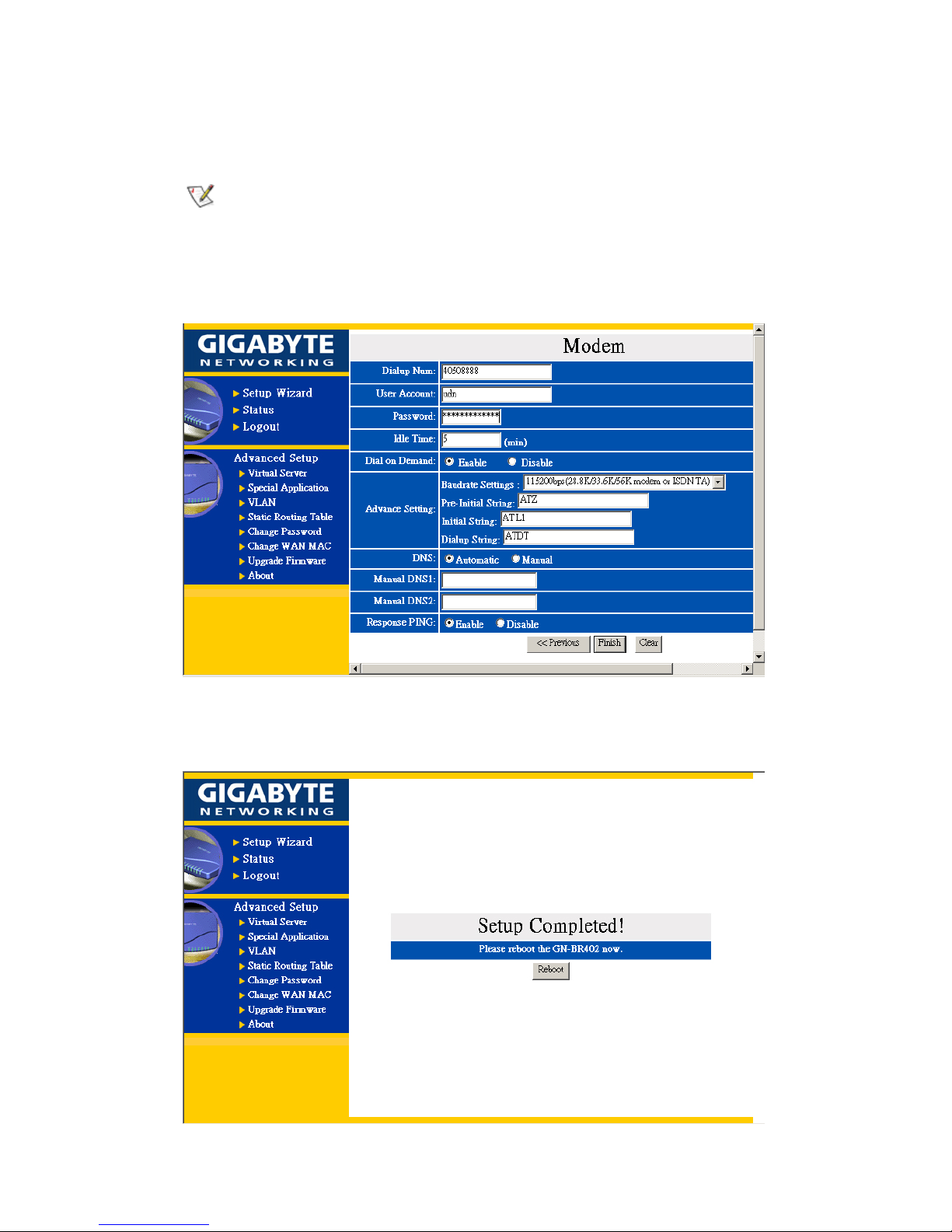
Step 18. If you select “PPP(Modem)” in the WAN TYPE SELECT, please key in the data provided
by the ISP company in the following blanks , then click “finish” , shown as below:
Dailup Num, User Account and Password :
Those data are assigned from your ISP.
Advance Setting:
Each setup item of the Modem Advance setting is default setting, and is not
necessary to make change to it for normal operation.
Step 19. After “Reboot” is pressed, it proceeds with the next step.
Page 39
37
Step 20. Please wait for a moment.
Step 21. The IE browser will be automatically connected to the main
menu, and the setup at the PC end is completed by then.
Please use your IE connect to Internet.
After rebooting successfully, the Modem will begin dailing-up. When it establishes the
connection then it means you can surf the Internet.
Page 40
38
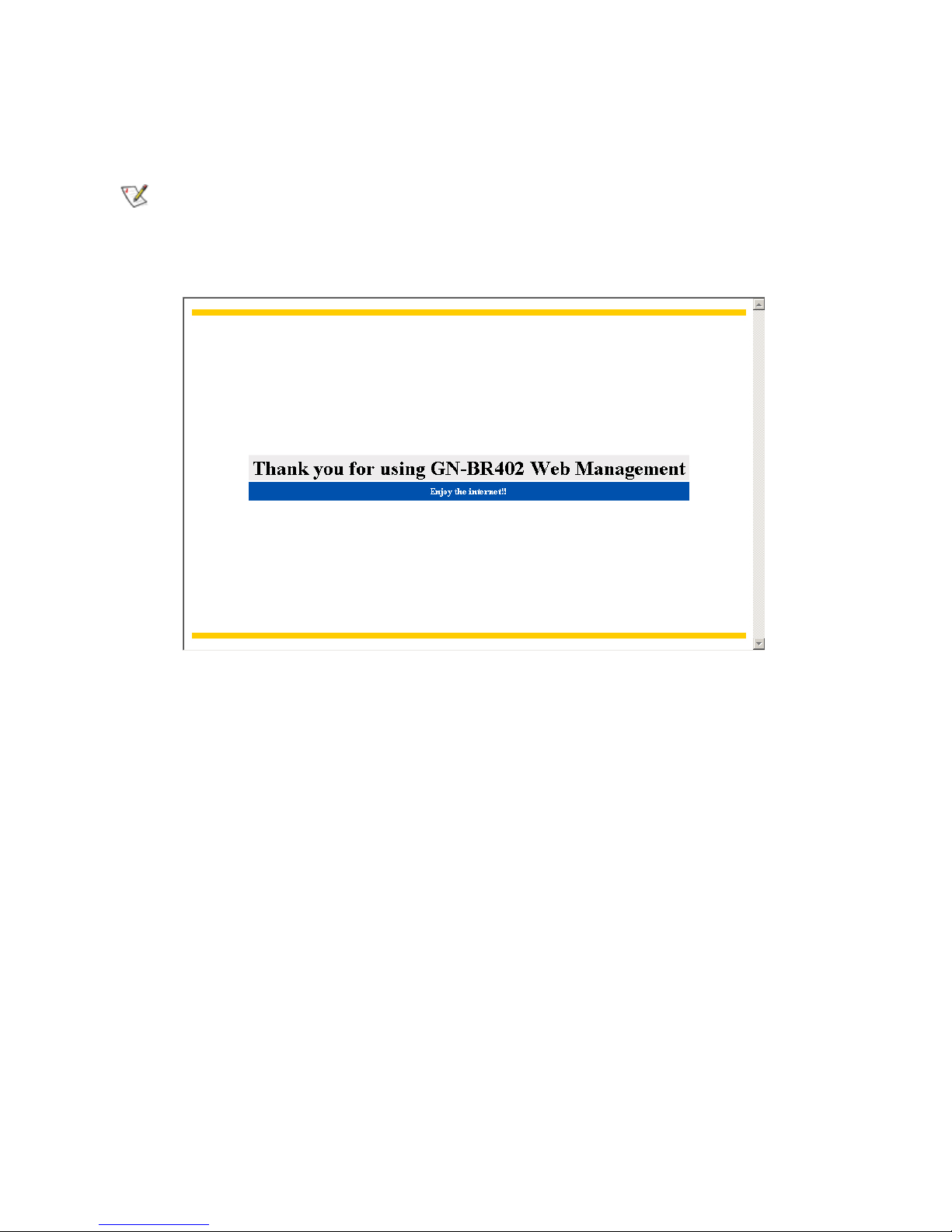
3-4 Logout
After you finish GN-BR402 setup, please choose “ Logout”.
If you don’t exit GN-BR402 Web Management by clicking “Logout” then GN-BR402 Web
Management will be occupied by this computer for up to 5 minutes idle time. No others can use
Web Management function during this period.
Page 41
39
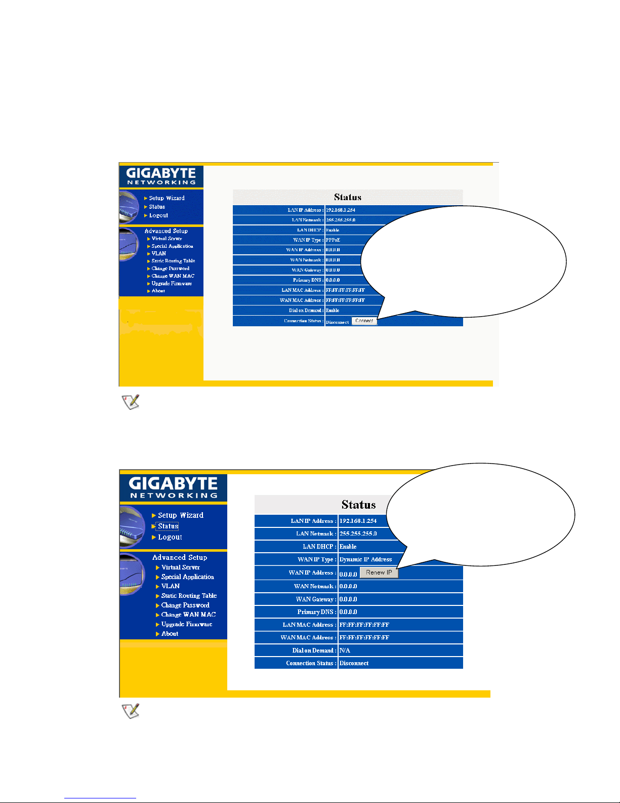
4. Status
- “ Status” screen shows the current basic network setting status.
Status 1. If you select “PPPoE” in the WAN TYPE SELECT, press “Status”, and the screen shows
as follows:
Your network service provider automatically obtains each of the above IP address at
the WAN end.
Status 2. If you select “Dynamic IP Address” in the WAN TYPE SELECT, press “Status” screen
as follows:
Your network service provider automatically obtains each IP address of the above
WAN end.
You can press the “function”
b
otton to configure the
connection status “connect”
or “disconnect” manually.
You can press the
“function” botton to renew
the WAN IP Address
manually.
Page 42
40
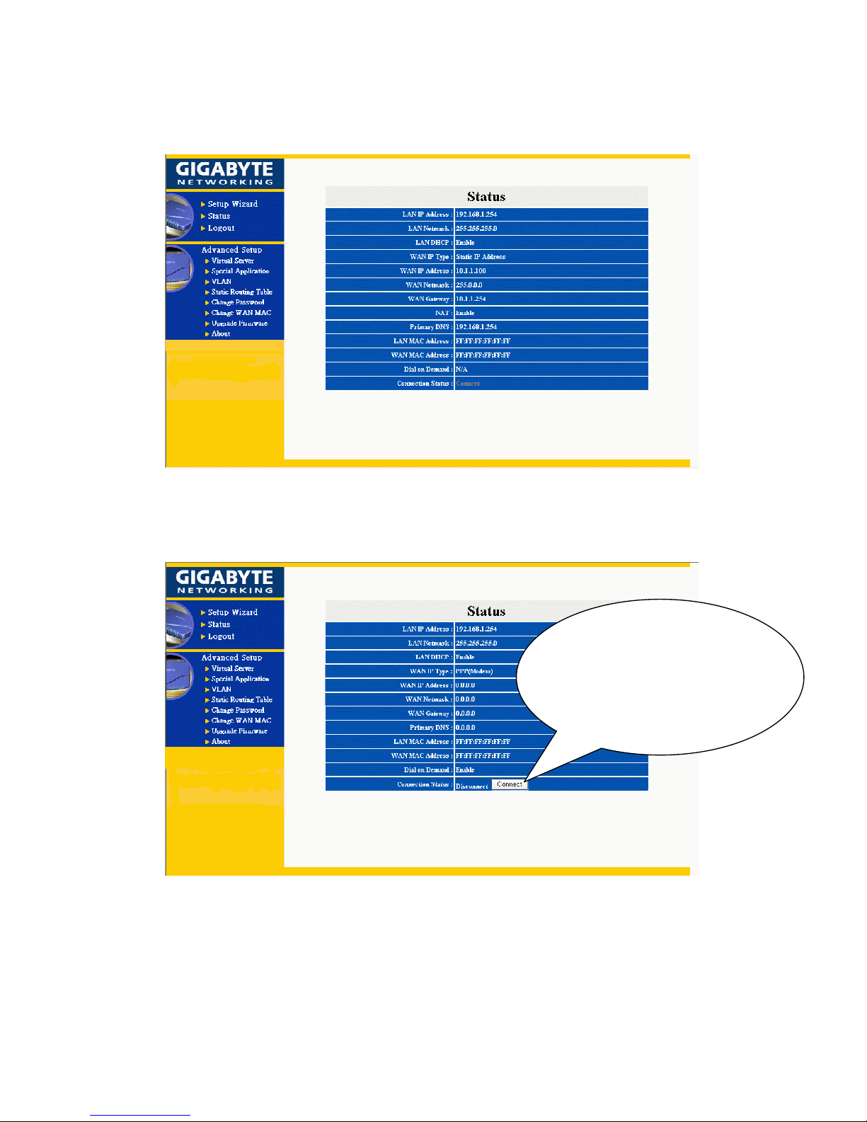
Status 3. If you select “Static IP Address” in the WAN TYPE SELECT, press “Status”, and the
screen shows as follows:
Status 4. If you select “PPP (Modem)” in the WAN TYPE SELECT, press “Status”, and the screen
shows as follows:
You can press the “function”
b
otton to configure the
connection status “connect”
or “disconnect” manually.
Page 43
41
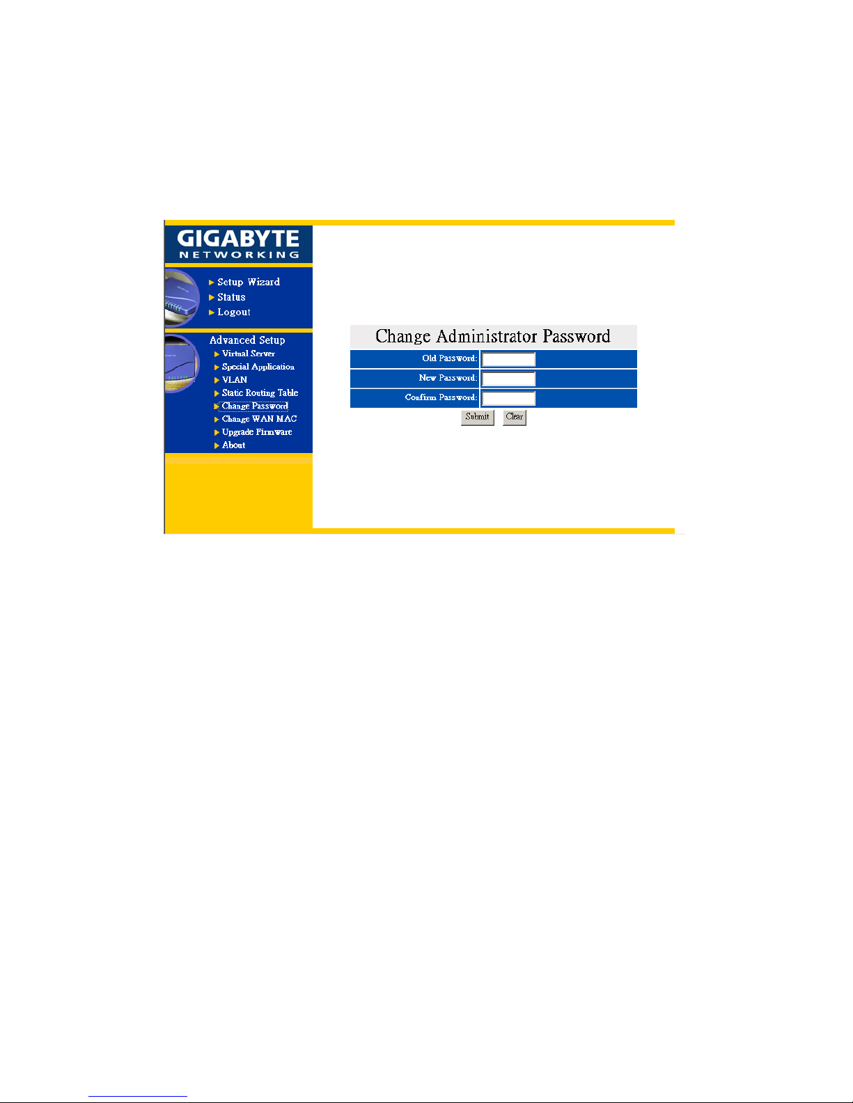
5. Change Password
- Key in your old password, and key in your new password. After your confirmation, key in
your new password once again, and the procedure will complete after you press: “Submit”.
Page 44
42
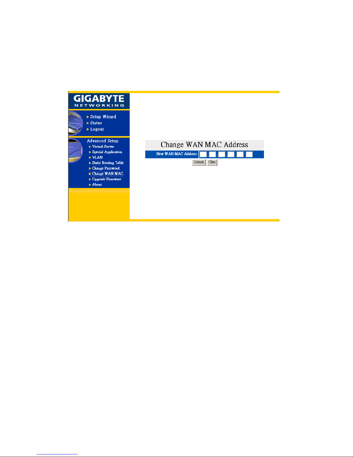
6. Change MAC address
- If your ISP Company asks you to use the original MAC address. You can enter your MAC
address at this place.
Page 45
43
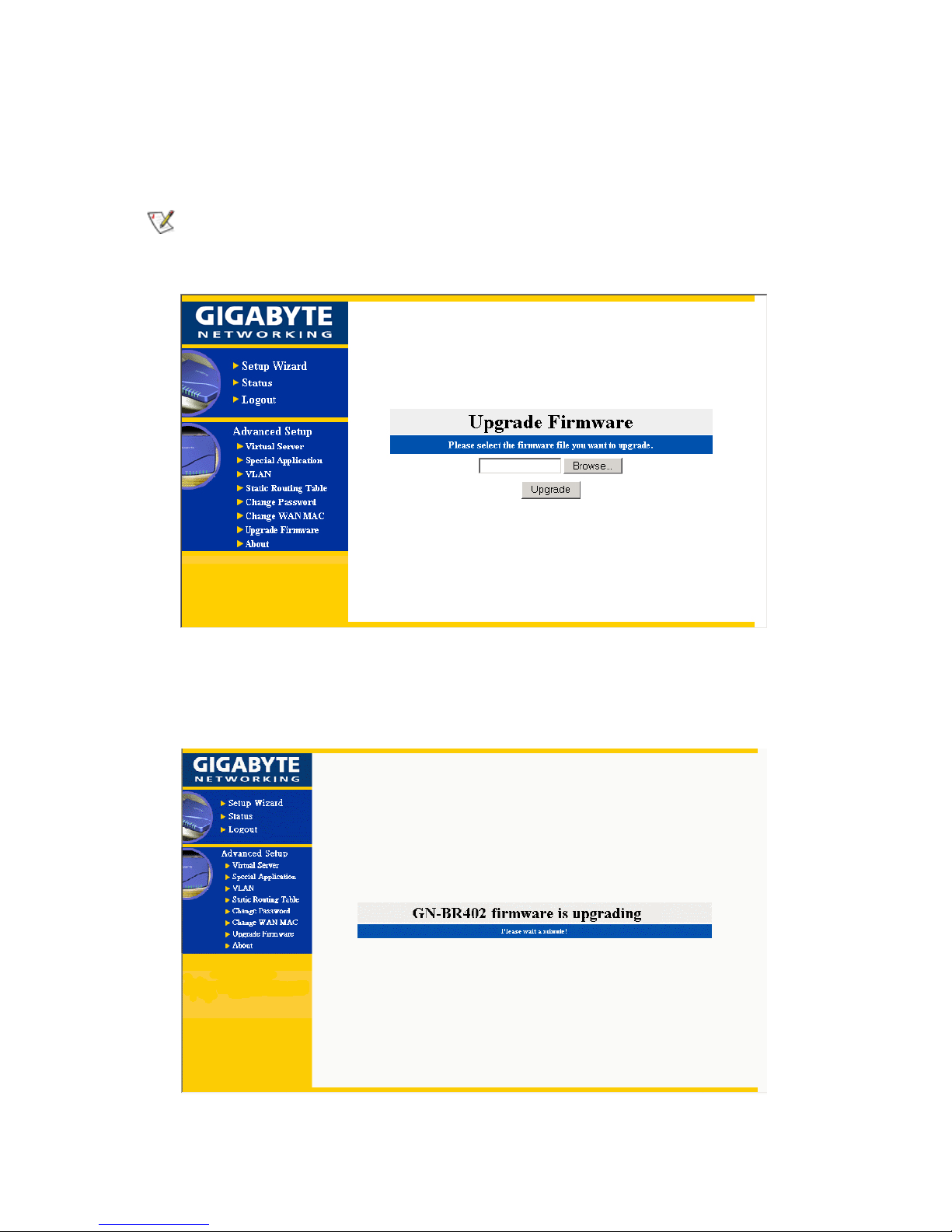
7. Firmware Upgrade
- Please browse and select your desired upgrade file (firmware version), and press upgrade.
You can download the upgraded firmware version from Gigabyte website and please
confirm what type of the firmware that you want to upgrade.
Please wait a moment, and the IE browser will be automatically connected to the main menu, and
the setting of our firmware upgrade is completed.
Page 46
44
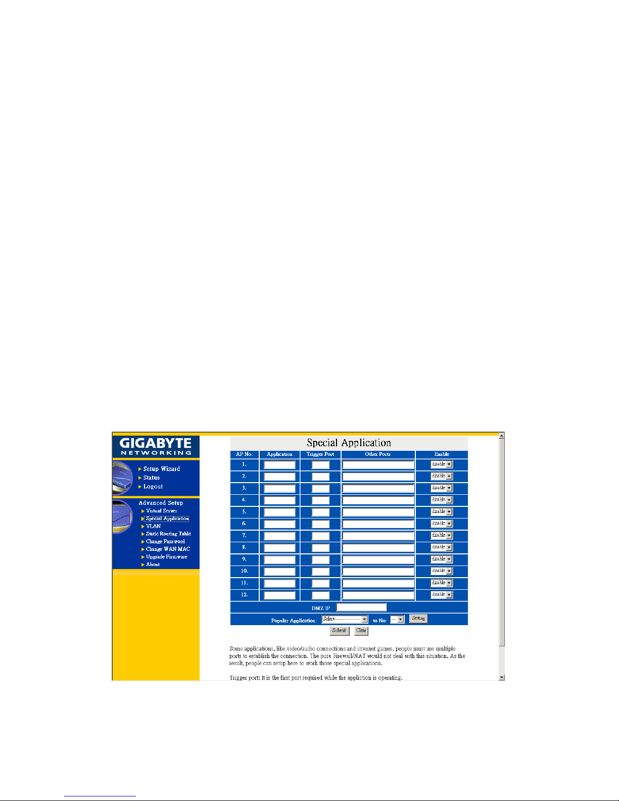
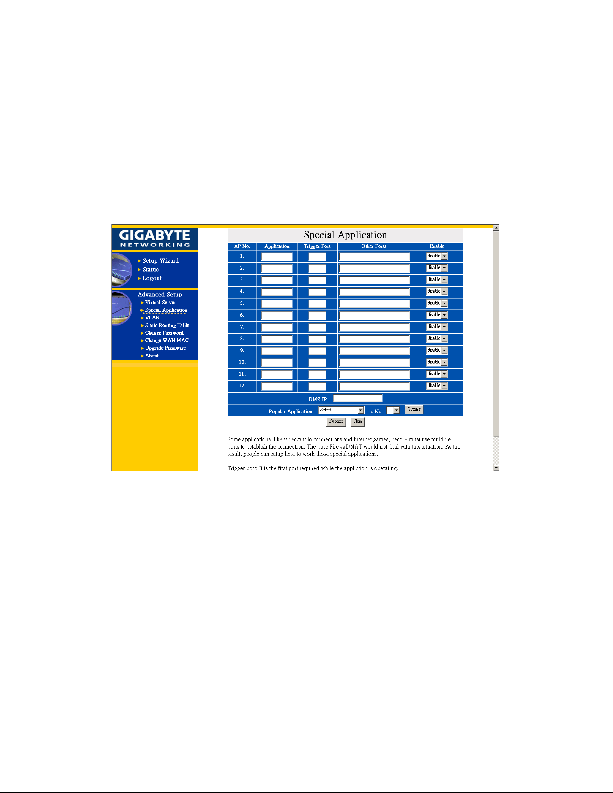
8. Instruction of Using Special Application
When special application program users at the LAN end want to use a certain network application
program, such application program needs more set up than the regular connection, and most of these
application programs are games or audio/video multimedia. Take AOK (Age of Kings) for
example:
- Application: AOK
- Trigger Port: 47624
- Other Ports: 2300 2400,28800 29000
- Enable: enable
1. Application: Key in the desired software name, such as AOK (Age of Kings); it only needs an
input for this field, and its value will not affect the operation of the GN-BR402.
2. Trigger Port: A port number.
3. Other Ports: The port interval of each section that needs to open is separated by a “space” (e.g.
2300 2400), and each interval is separated by a “comma” (2300 2400, 28800 29000).
4. Enable: Select “enable” to open such setting.
Several common application program set-ups are provided at the bottom of the screen. The user can
complete the settings by clicking the mouse.
Page 47
45
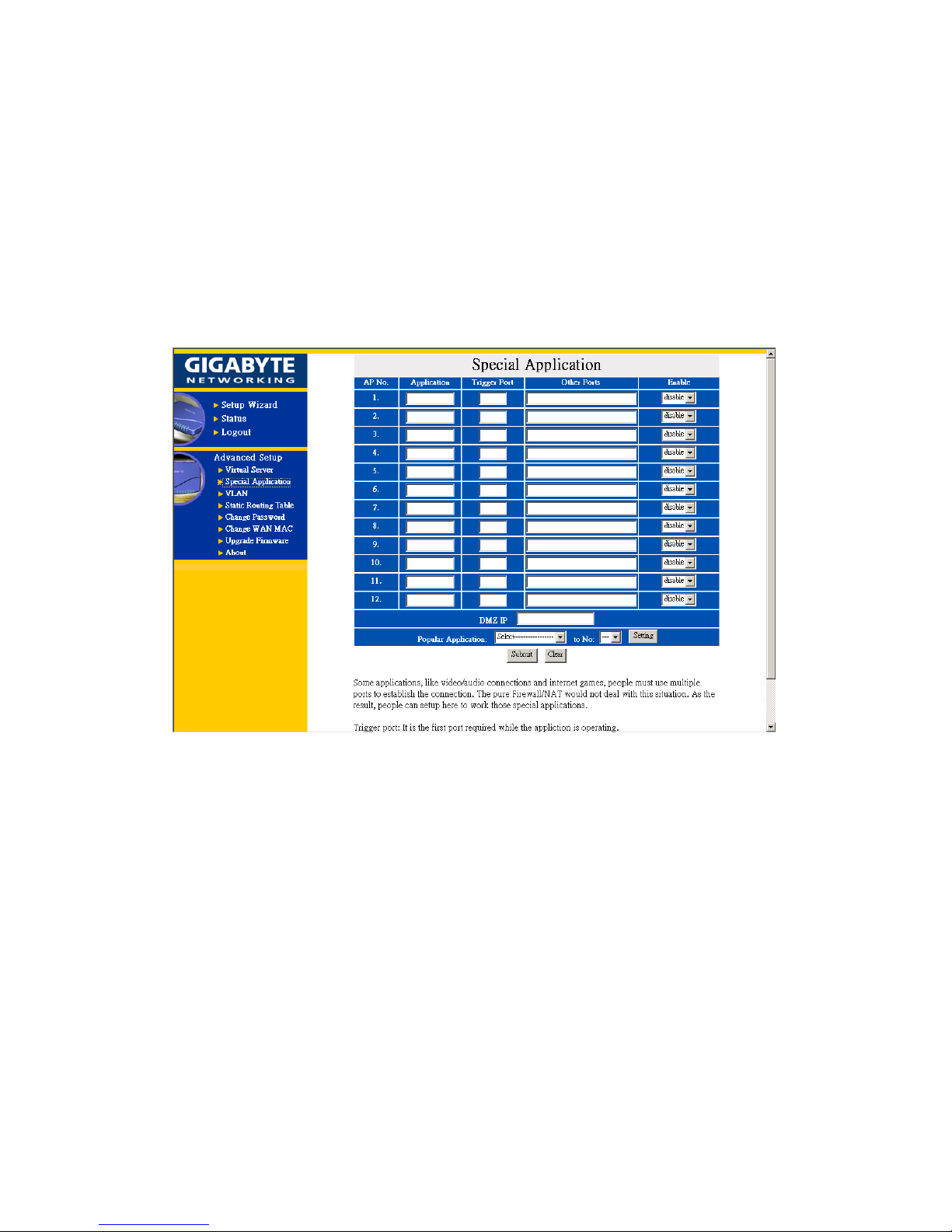
8-1 Instruction of Using DMZ
If we do not know how to set up the triggered port or port number of special application, then the
IP Address (such as 192.168.1.1) of PC at the LAN terminal can be used to input to the field of
DMZ. Taking NetMeeting for example, if you just want to call an external computer from the
computer at the LAN terminal, it does not need any set up. However, if you want to let the external
PC to call the computer at the LAN terminal, then the virtual IP Address must be filled in the field of
DMZ.
Page 48
46
8-2 Instruction of Using Netmeeting
1. If we need to actively call the PC of the external network from the PC at the LAN terminal, it
does not need special set up.
2. To let a PC at the WAN end call a PC at the LAN end, set the virtual IP Address (such as
192.168.1.1) of the PC at the LAN end to the DMZ field in the Special Application as shown in
the following figure. The PC at the WAN end can call the external IP Address (provide by the
ISP) of the GN-BR402, and the internally connects to such PC.
Page 49
47
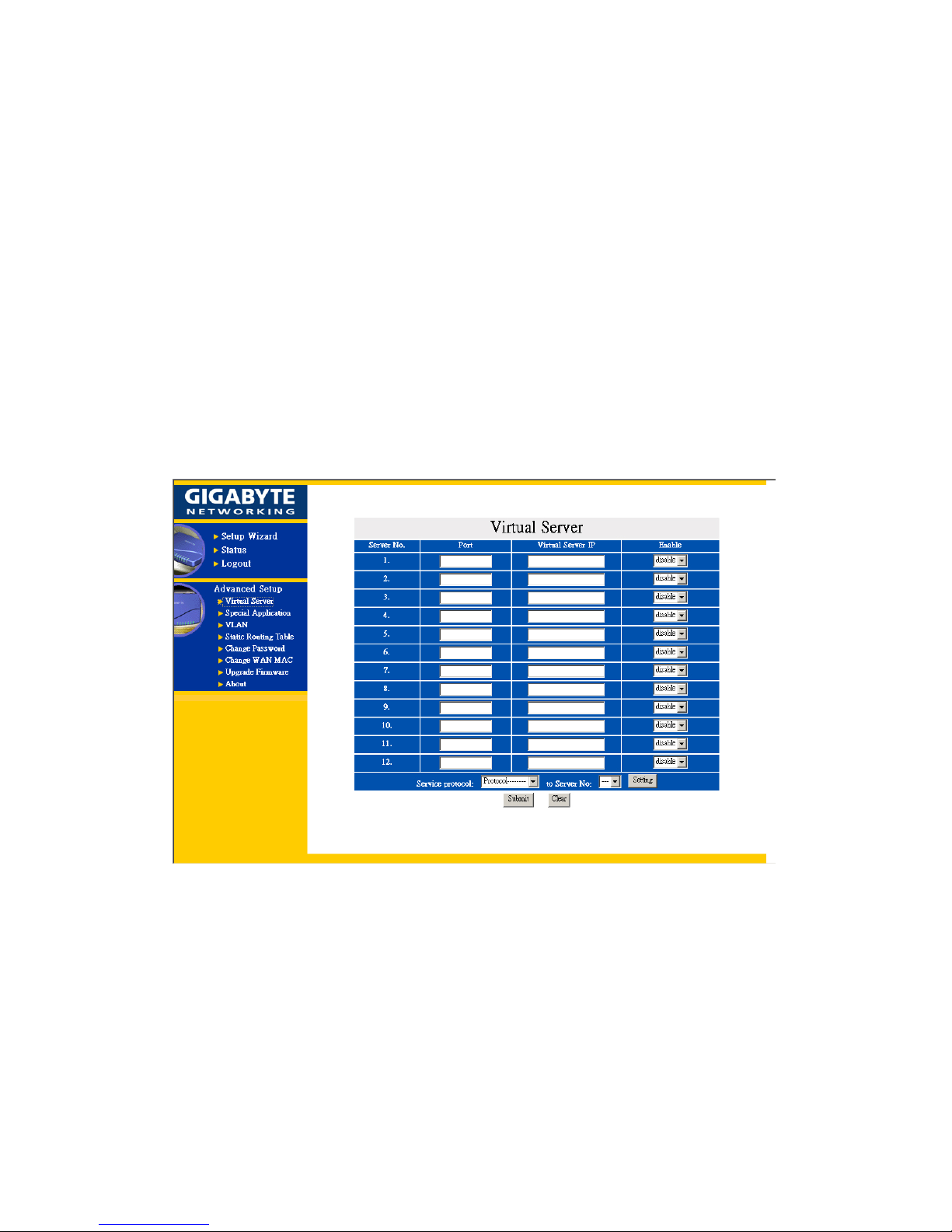
9. Instruction of Using the Virtual Server
Virtual server provides a way to let the PC at the WAN end connect to a server of a PC at the LAN
end.
Taking the IP Address 192.168.1.1 of a PC on a FTP (port:21) at the LAN end for example:
Port: 21
Virtual Server IP: 192.168.1.1
Enable: enable
The PC at the WAN end can connect to the internal FTP server at the IP address 192.168.1.1 via the
WAN end of the IP Address of the FTP GN-BR402.
At the bottom of the screen, we provide several common server port numbers for the setting, and the
user can click one of them, and then fill in the virtual IP address set for the server to complete the set
up.
Page 50
48
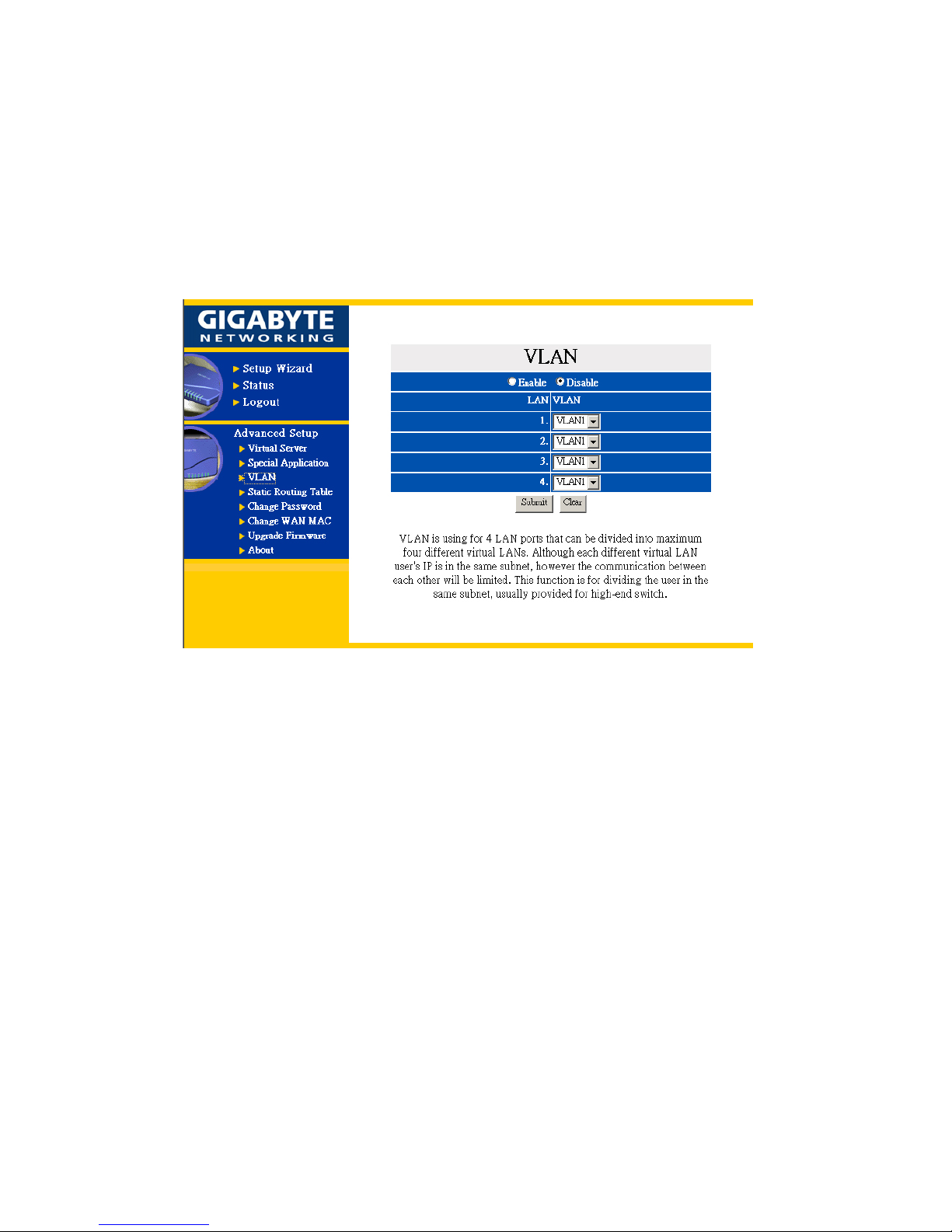
10. VLAN
VLAN is using for LAN ports that can be divided into maximum four different virtual LANs.
Although each different virtual LAN user’s IP is in the same subnet, however the communication
between each other will be restricted. This function is for dividing the users in the same subnet,
usually provided for high-end switch.
Page 51
49
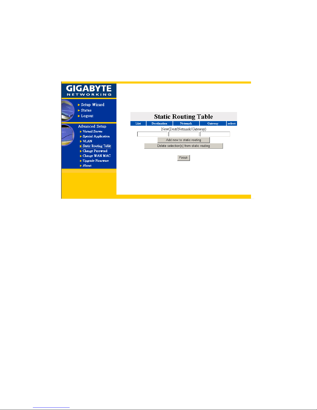
11. Static Routing Table
Under some of Internet environments, some of the subnet do not go through the default gateway.
Users can add those routing information to Static Routing Table themselves.
You can enter new routing information and click “Add new to Static routing” then there will add the
new routing information to Static Routing Table. Otherwise, you can mark the checkbox of the
routing table that you want to delete and click “Delete selection(s) from static routing” then there
will delete the marked routing information from Static routing table. Press “Finish”.
Page 52

50
12. Troubleshooting
Q: What to do if you forget your password or forget the IP address of the GN-BR402?
Please press the “init” bottom on the GN-BR402 about 5 sec. The GN-BR402 will be restart and
the system setting will restore to default value.
Q: Unable to connect to Internet?
Please confirm whether or not the power cord is connected properly, and the power
indicating light of the GN-BR402 is normal.
Please confirm whether or not all of the settings described in this manual are set.
Please confirm if ADSL or Cable Modem operates properly, and if the ISP network service
expires.
Please confirm if your network cable is connected properly, and the LED status is normal.
Page 53
51
13. Appendix
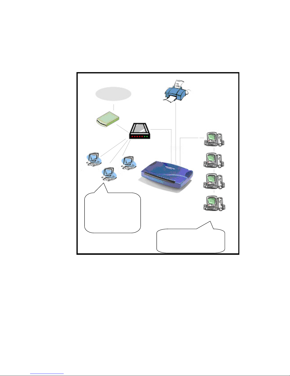
(A) GN-BR402 Functional Diagram
Printer
Internet
Cable/ADSL
Modem
LAN port
WAN port
PC1
If your wideband company
provides other 3 sets of
static IP addresses please se
t
them to PC5, 6, and 7.
GN-BR401automatically provides
the IP address of DHCP
PC2
PC3
PC4
PC5
PC6
PC7
Switch/Hub
Page 54
52
(B) USB Driver Installation
Preface
1. Before installing the USB driver, please refer to Section 3-2 for the installation at your PC end.
If “obtain an IP address automatically” is not selected in the installation at your PC, then you
should know the following information:
IP address ranges from “192.168.2.1” to “192.168.2.252”
Subnet Mask “255.255.255.0”
Default Gateway “192.168.2.253”.
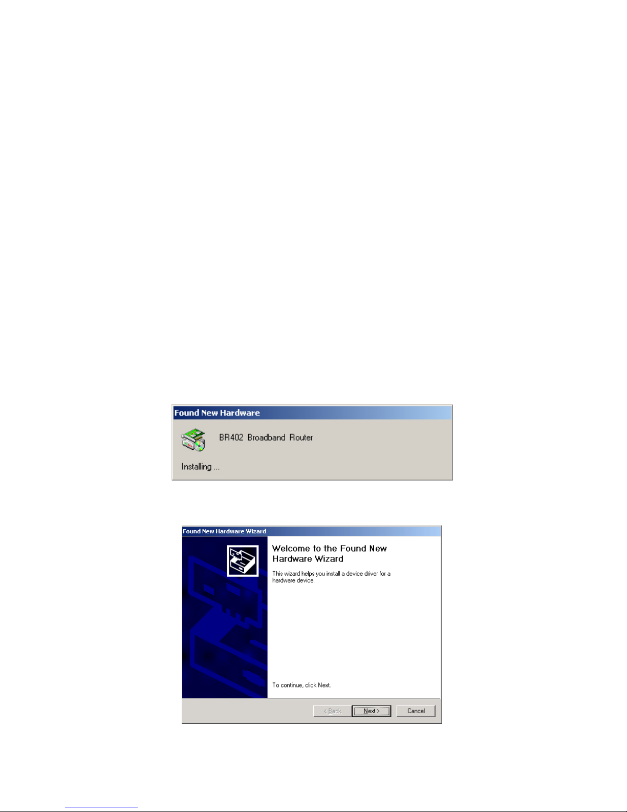
2. Follow the “Found New Hardware Wizard” to complete the GN-BR402 USB Driver Installation.
Steps:
Please connect the power to the GN-BR402 and wait until the GN-BR402 completely boots up
(when the status LED is off). Connect the USB cable to the USB slot on your computer and the
USB slot of the GN-BR402.
The following screen will appear:
Please press “Next” for next step.
Page 55
53
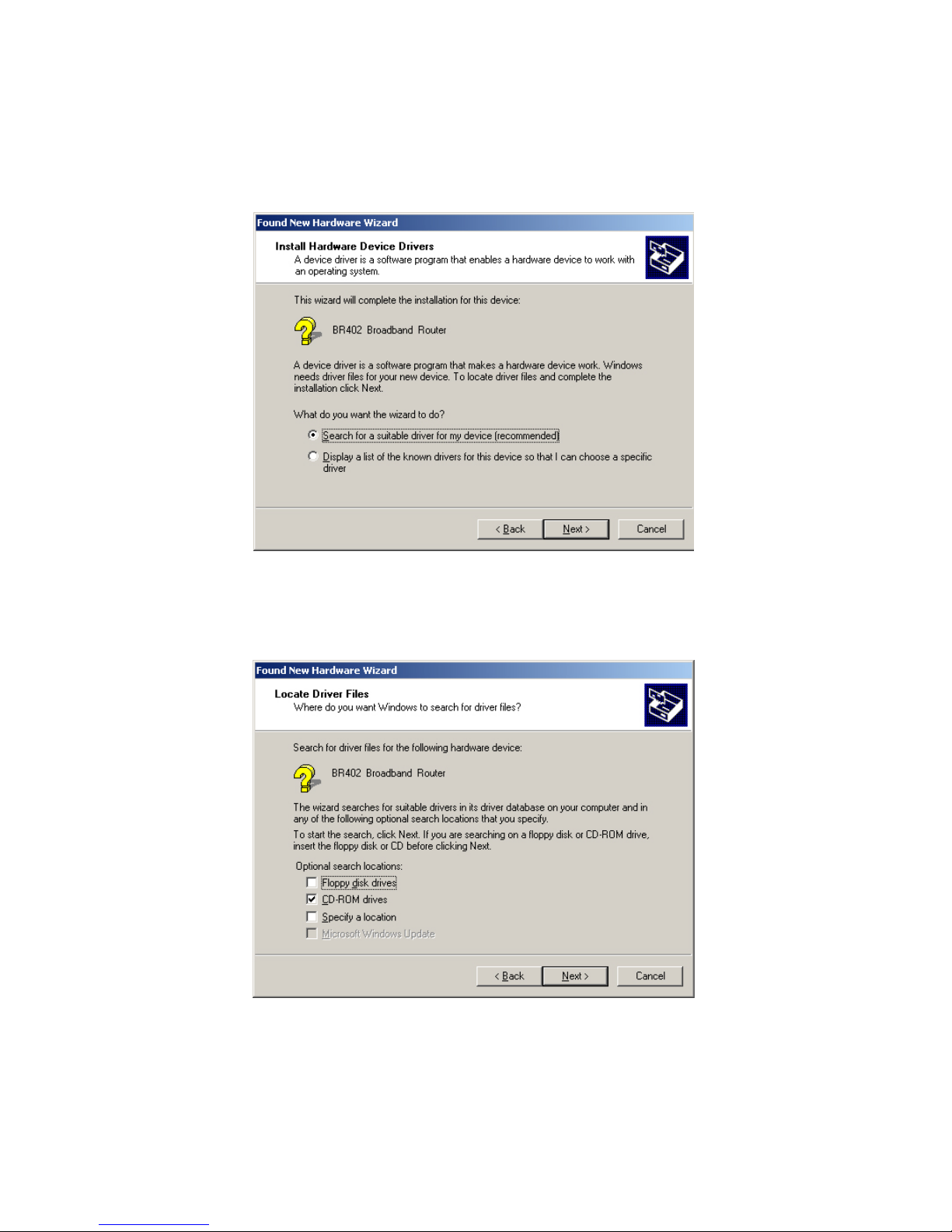
Please choose “Search for a suitable driver for my device (recommended)”, and then press “Next”
for next step.
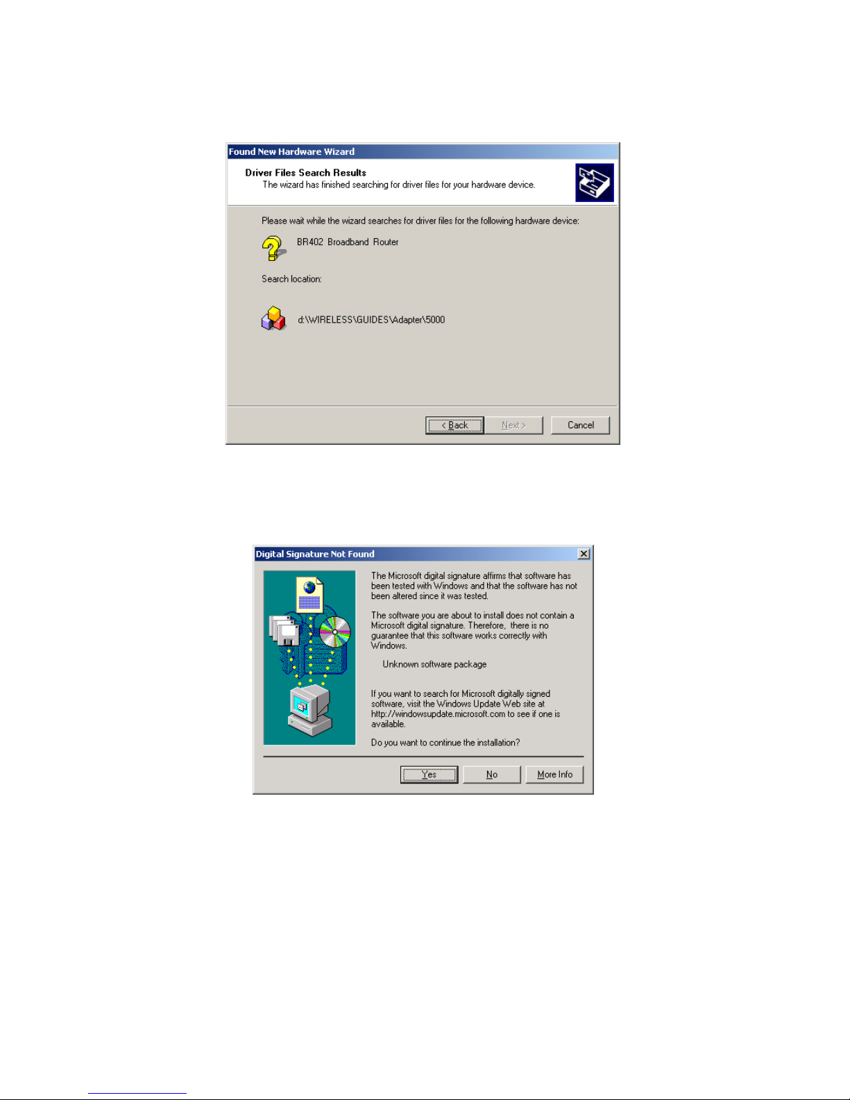
Please choose the location where you place the GN-BR402 Driver , and then press “next”.
Page 56
54
Please click “Next” for next step.
Please click “Yes” for next step.
Page 57
55
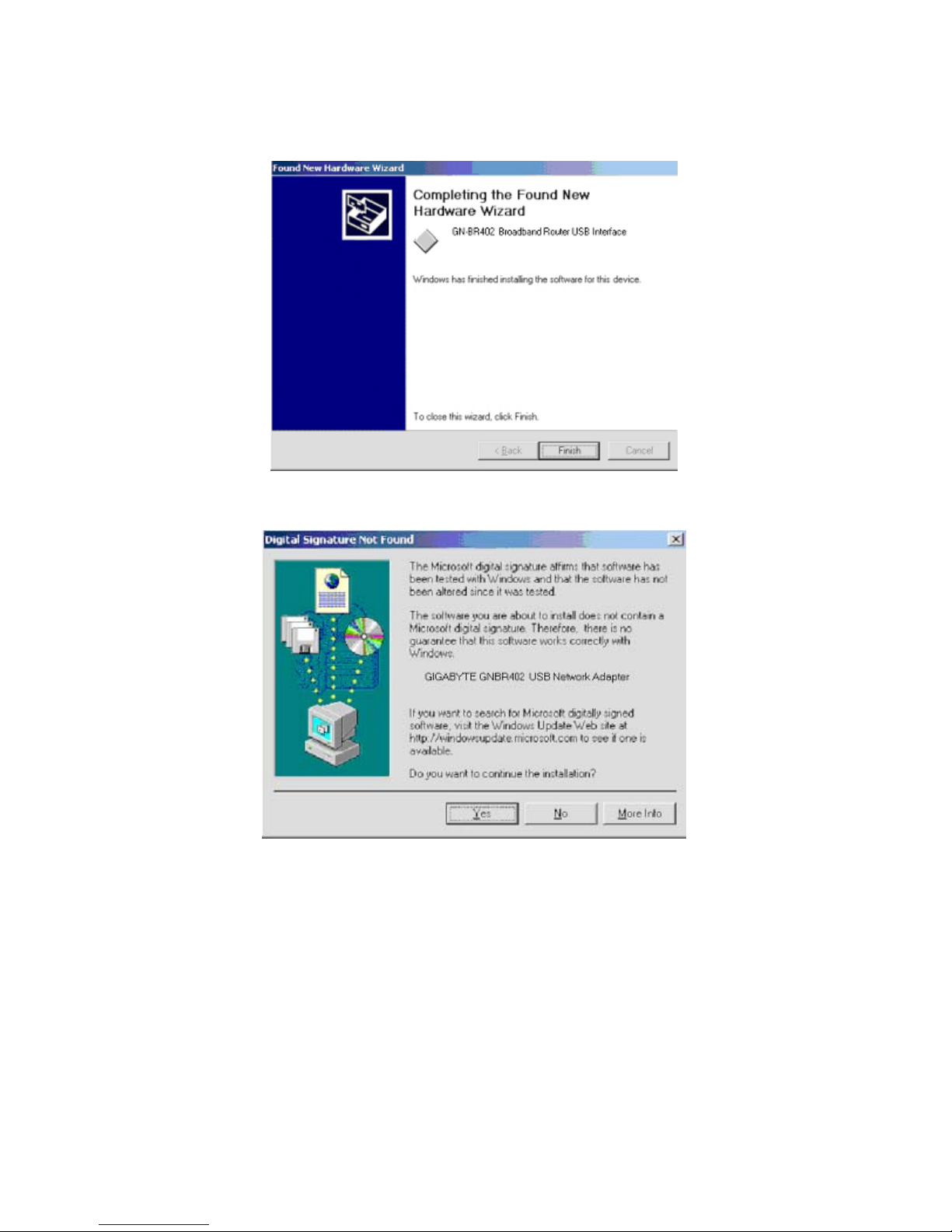
Please click “Finish” for next step.
Please click “Yes”. NOW YOU HAVE COMPLETED THE USB DRIVER INSTALLATION.
Page 58
56
(C) Instruction of Printer Server
The GN-BR402 Broadband Router can be as a Printer Server, Please follow the setup procedure in
Printer Setting. Example as follow:
( This function can not support bidirectional printers.)
Windows2000
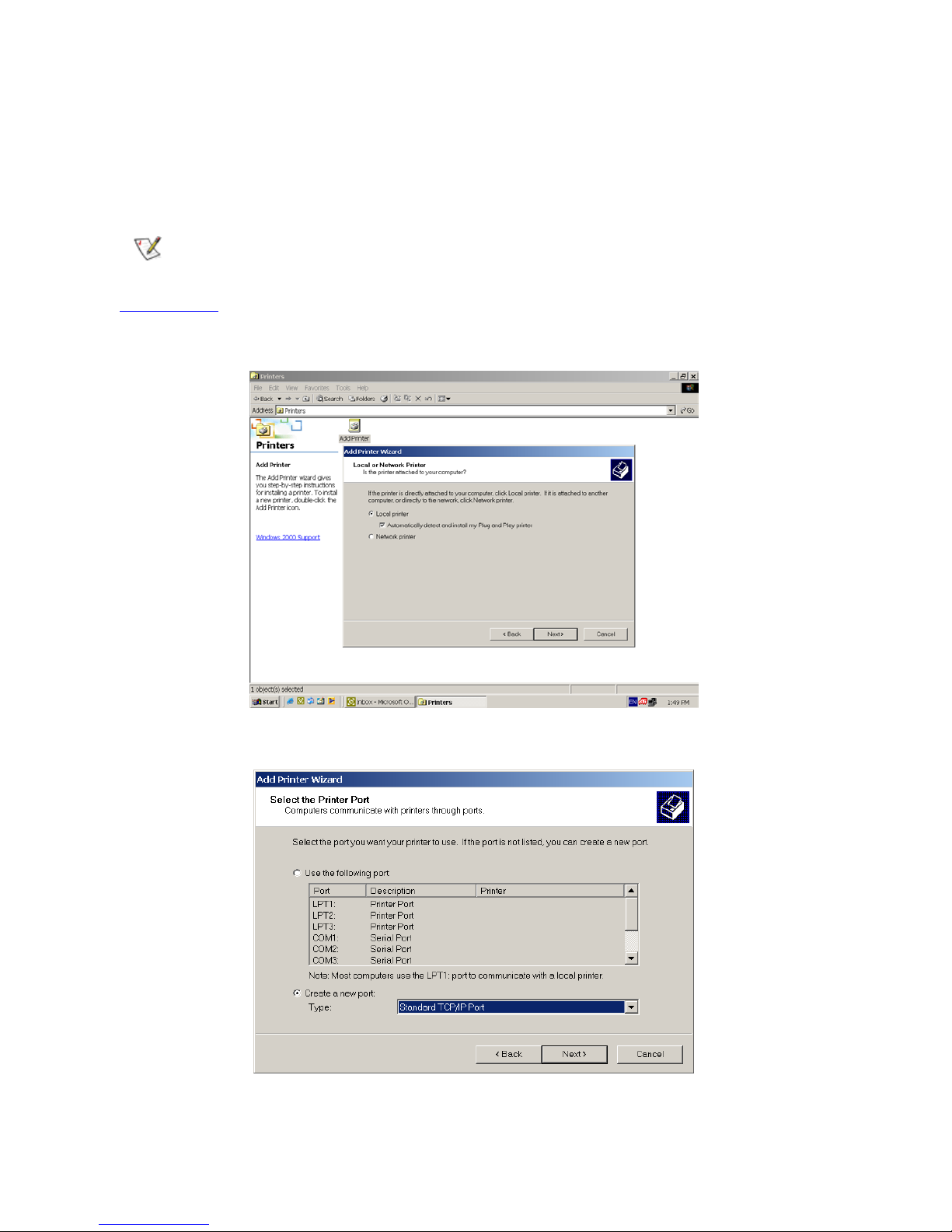
Start > Setting > Printer, Double-Click Add Printer. The Add Printer Wizard dialog will be displayed,
please select the Local Printer option and press “Next”.
Select Create a new port option, Type: “Standard TCP/IP Port” then press “Next”.
Page 59
57
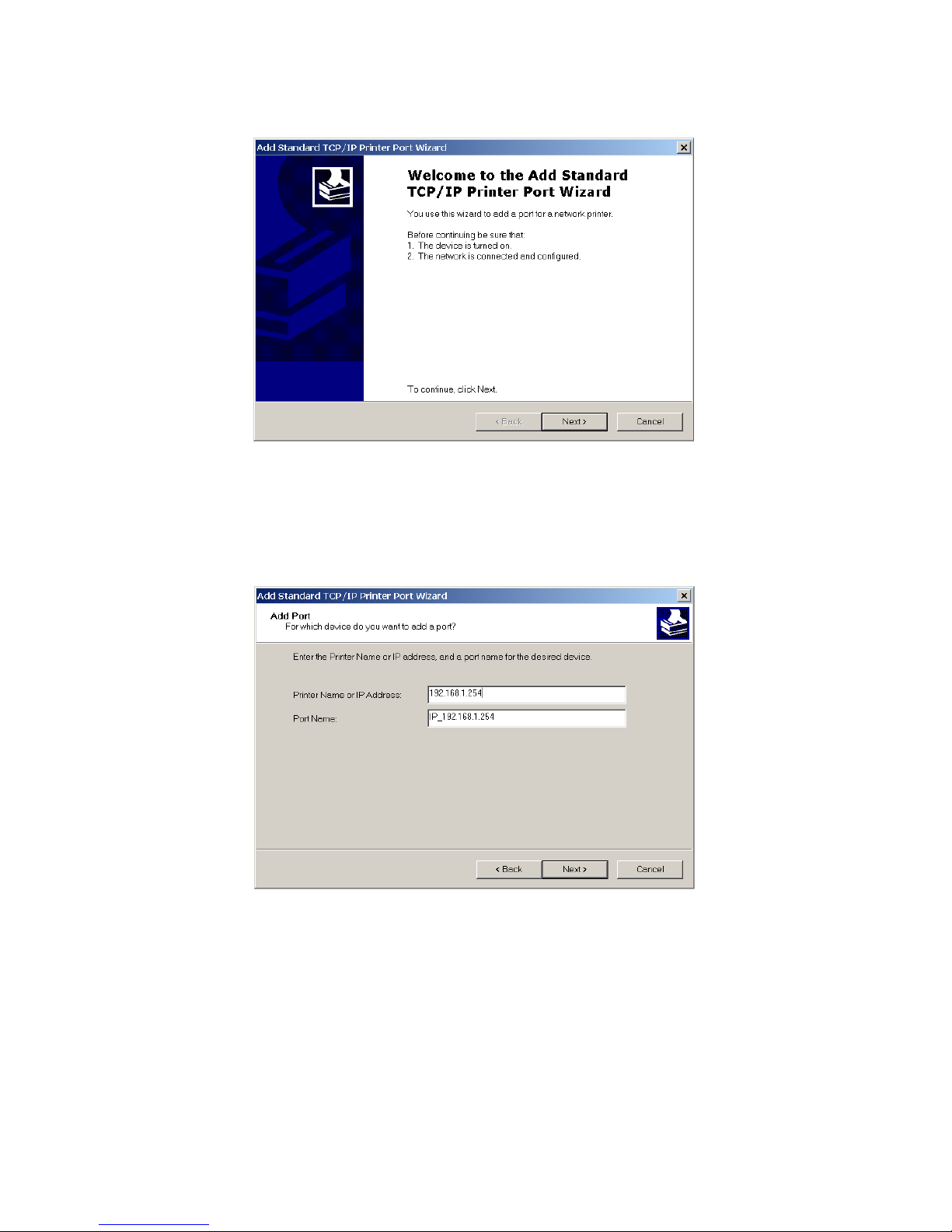
Press “Next”.
Please enter the Printer Name or IP Address : 192.168.1.254 and the Port Name : IP_192.168.1.254,
Press “Next”.
Page 60
58
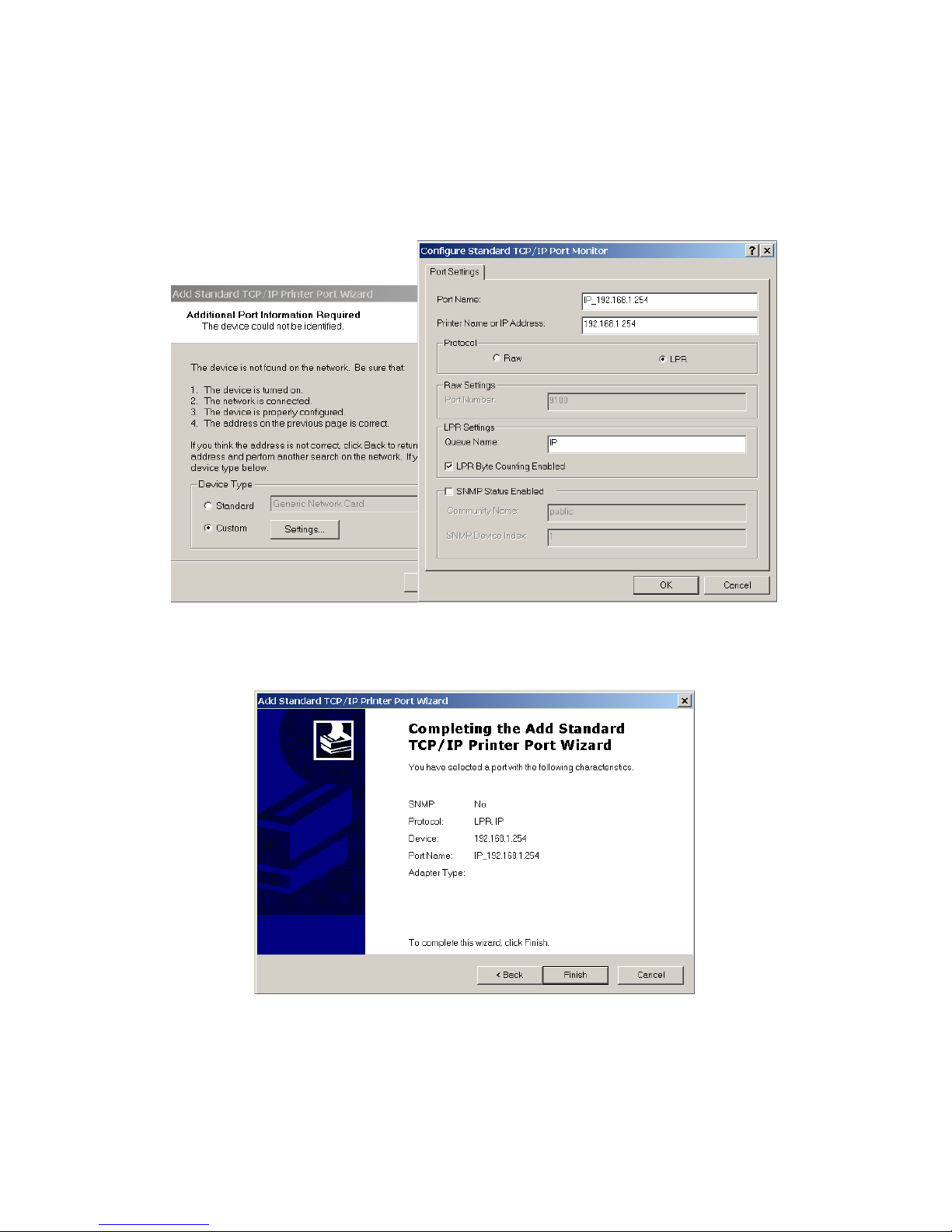
The Device Type selects Custom option and press “Setting”. The Configure Standard TCP/IP Port
Monitor dialog will be displayed. Enter the Port Name: IP_192.168.1.254 and Printer Name or IP
Address is 192.168.1.254. Select the LPR Protocol and enter the Queue Name: lp and select the
LPR Byte Counting Enabled check box in the LPR setting then press “OK”.
Press “Finish”.
Page 61
59
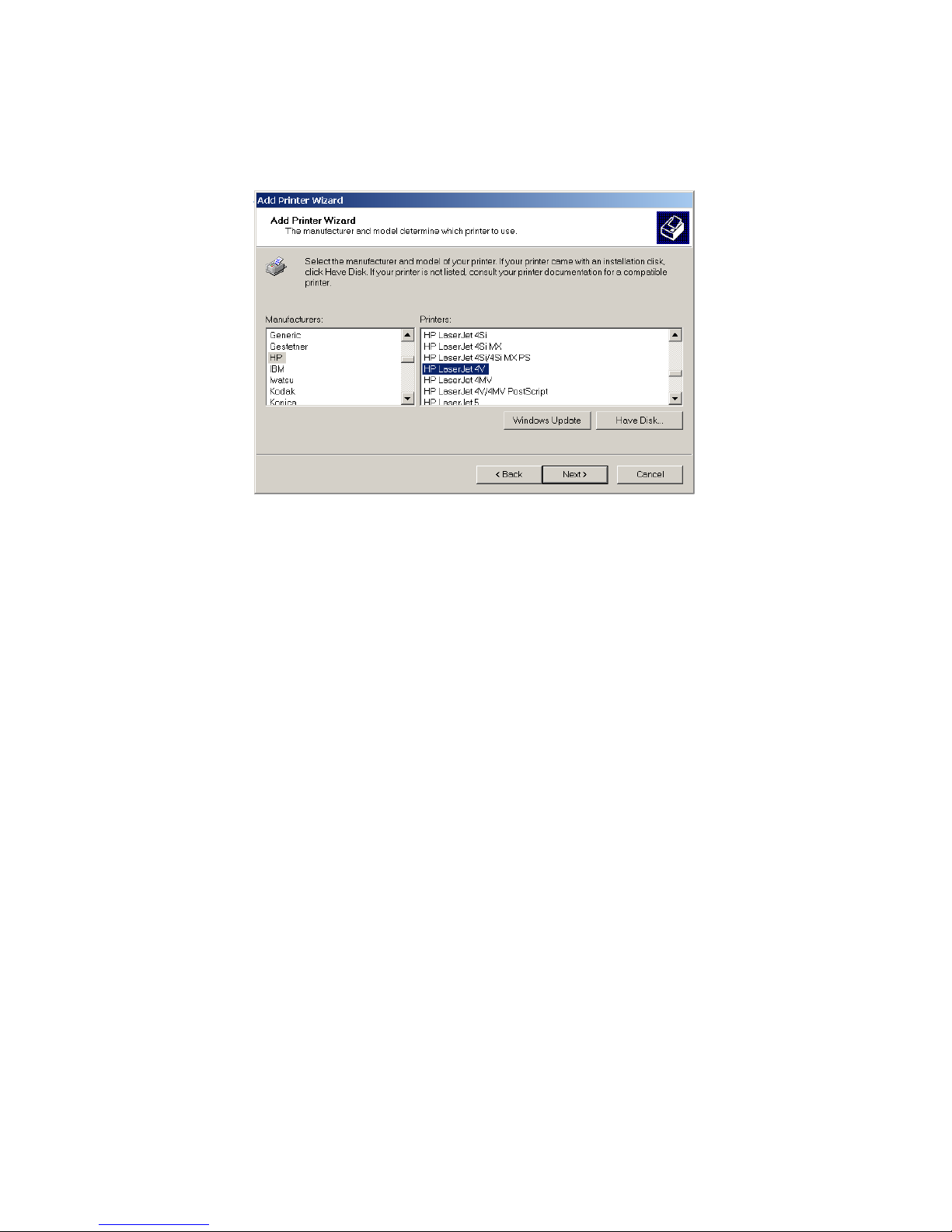
Select the manufacturer and model of your printer. (If your printer is not listed, click “Have Disk ”
to install your printer driver.) Click “Next”, the wizard will help you finish the installation
automatically.
Page 62
60
Windows 95/98/ME
For the Windows95/98/ME Operation system, users must install the Giga LPR software to support
the “Printer Server” function of the GN-BR402. Installation procedures as following:
Win95: please start at Step1 ~ Step7. Win98/ME: please start at step3 ~ step7.
Before installing the Giga LPR software, it is necessary to upgrade the Win95 Socket for the
Windows 95 operation system .
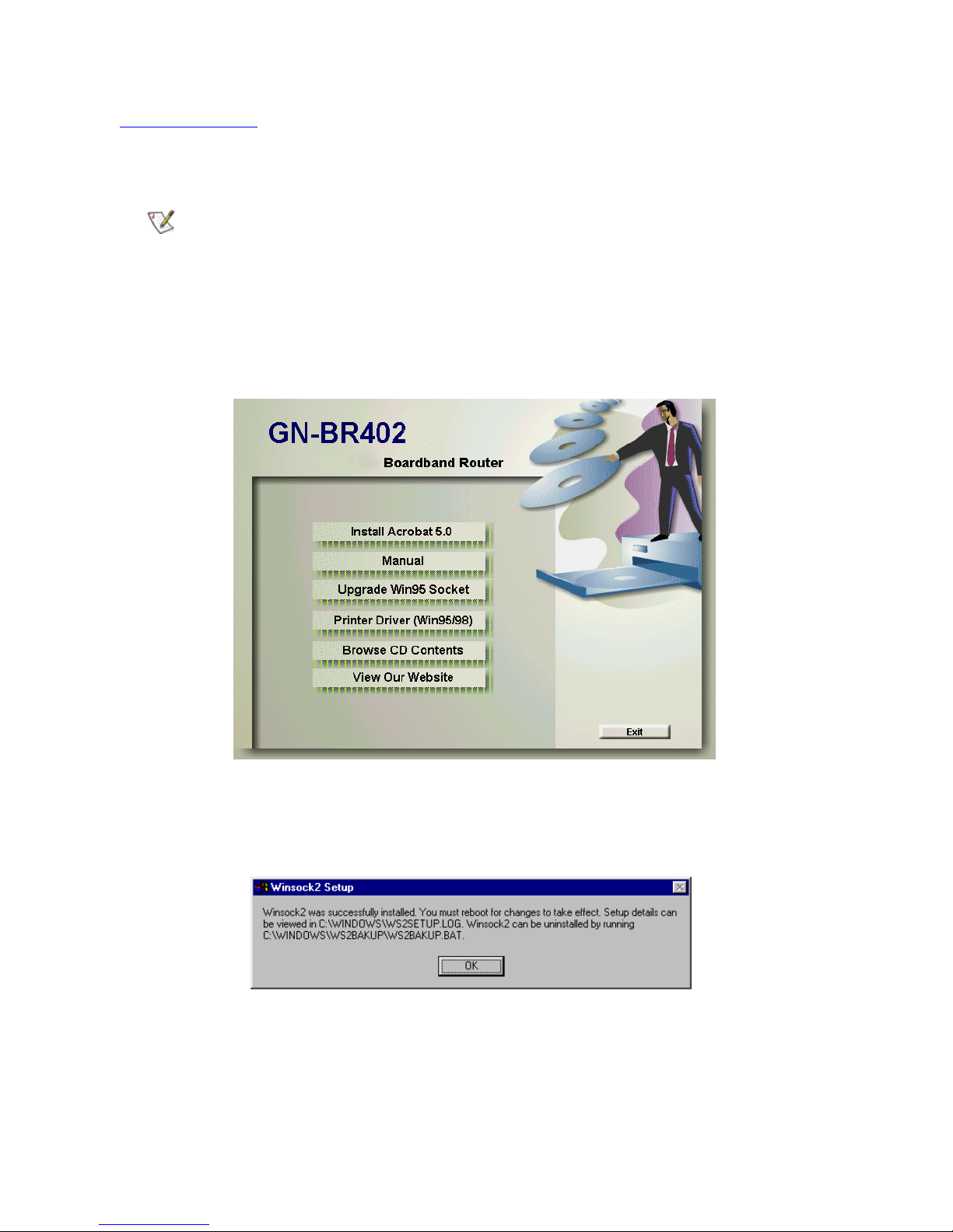
Step1. Please insert the GN-BR402 Driver CD into the system’s CD-ROM drive. Click “Upgrade
Win95 Socket” on the CD autorun screen.
Step2. The Winsock2 Setup screen will appear. Click “OK” and return to the CD autorun screen,then
continue to install the Giga LPR software.
Page 63
61
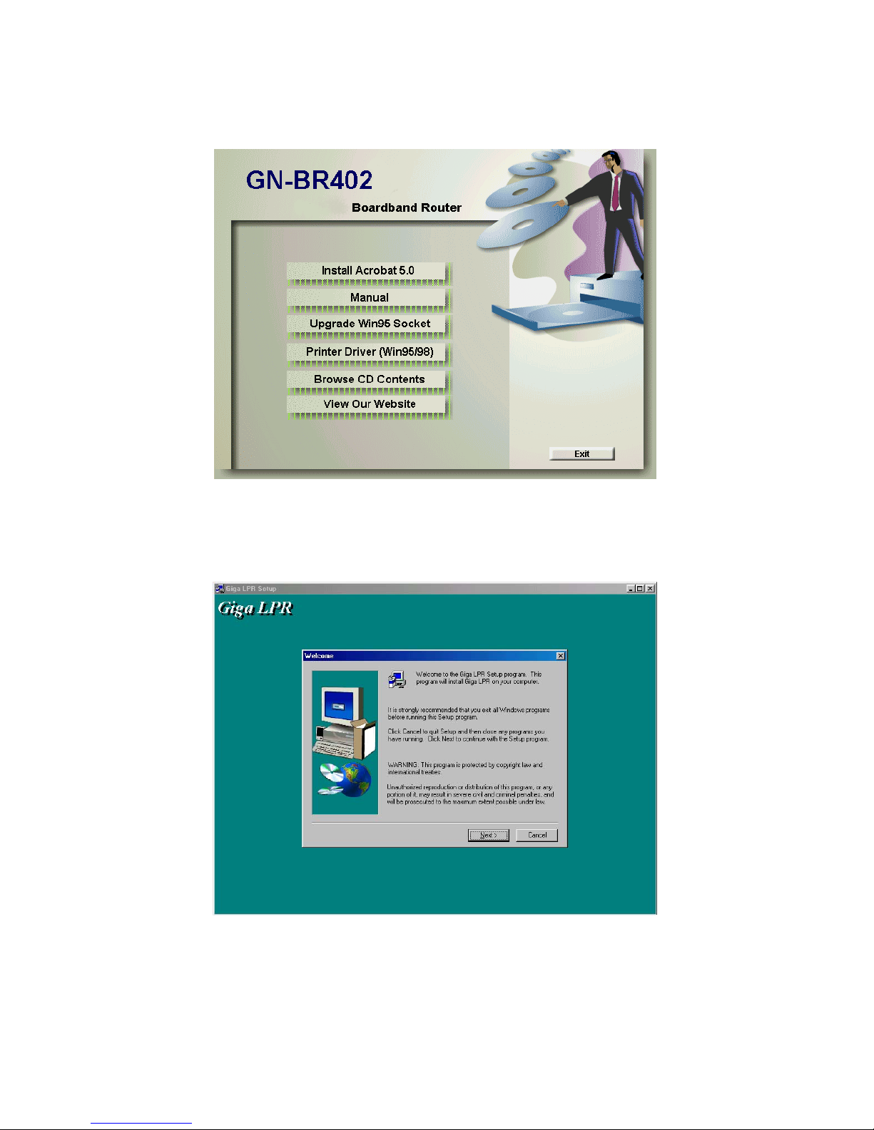
Step3. (Please insert the GN-BR402 Driver CD into the system’s CD-ROM drive.) Click the “Printer
Driver(Win95/98)” on the CD autorun screen.
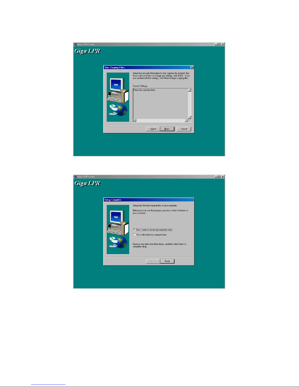
Step4. The Welcome dialog is displayed and click “Next”.
Page 64
62
Step5. Click “Next”.
Step6. Click “Finish” and restart the computer.
Step7. Please follow the “Add New Printer” procedures, however please notice that “Available
Ports” need to be chosen for the “Giga LPR”;and click “Configure Port..” bottom to make
sure that Printer server’s IP address is “192.168.1.254” (default value).
Page 65
63
Limited Warranty
1-Year Warranty
Gigabyte warrants to the original consumer/purchaser that the adapter product free from defects
in material and workmanship for no limited time from the original manufactory shipment date.
This warranty does not cover the adapter product if it is damaged in the process of being
installed or improperly used.
Gigabyte may replace or repair the adapter product with either new or reconditioned parts.
Repaired or replaced adapter products will be returned to you at the same revision level as
received or higher at Gigabyte’s option. Gigabyte reverses the right to replace discounted adapter
products with an equivalent generation adapter product.
KEEP THIS STUB FOR YOUR PURCHASING RECORD
Customer:
Phone No:
Address:
Email:
Model:
Serial:
Date of Purchase:
Place of Purchase:
From Whom:
Distributor:
Customer Satisfaction
GIGA-BYTE TECHNOLOGY CO., LTD.
No.6, Bau Chiang Road, Hsin-Tien, Taipei Hsien, Taiwan, R.O.C.
Tel: 886-2-89124888
Fax:886-2-89124007
http://www.gigabyte.com.tw
Technical Support
E-mail: [email protected]
TEL: 886-2-89124888 Ext:2222
Page 66

64
Safety, Care and Regulatory Information
Important safety instructions
Read and follow all instructions marked on the product and in the documentation before you operate your system. Retain all safety and operating instructions for future use.
The product should be operated only from the type of power source indicated on the rating label.
If your computer has a voltage selector switch, make sure that the switch is in the proper position for your area. The voltage selector switch is set at the factory to the correct voltage.
The plug-socket combination must be accessible at all times because it serves as the main disconnecting device.
All products hipped with a three-wire electrical grounding-type plug only fits into a grounding-t ype power outlet. This is a safety feature. The equipment grounding should be in accordance with local and national electrical codes. The
equipment operates safely when it is used in accordance with its marked electrical ratings and product usage instructions
Do not use this product near water or a heat source.
Set up the product on a stable work surface or so as to ensure stability of the system.
Openings in the case are provided for ventilation. Do not block or cover these openings. Make sure you provide adequate space around the system for ventilation when you set up your work area. Never insert objects of any kind into the
ventilation openings.
To avoid electrical shock, always unplug all power cables and modem cables from the wall outlets before removing covers.
Allow the product to cool before removing covers or touching internal components.
Use only the power cord and batteries indicated in this manual. Do not dispose of batteries in a fire. They may explode. Check with codes for possible special disposal instructions.
Precautions for Products With Modems, Telecommunications, or Local Area Network Options
Observe the following guidelines when working with options:
• Avoid using a telephone (other than a cordless type) during an electrical storm. There may be a remote risk of electric shock from lightning.
• CAUTION - To reduce the risk of fire, use only No. 26 AWG or larger telecommunication line cord.
• Do not plug a modem or telephone cable into the network interface controller (NIC) receptacle.
• Disconnect the modem cable before opening a product enclosure, touching or installing internal components, or touching an uninsulated modem cable or jack.
• Do not use a telephone line to report a gas leak while you are in the vicinity of the leak.
• Do not use this product near water, for example, near a bath tub, wash bowl, kitchen sink or laundry tub, in a wet basement or near a swimming pool.
Federal Communications Commission (FCC) Statement
Note: This equipment has been tested and found to comply with the limits for a Class B digital device, pursuant to Part 15 of the FCC Rules. These limits are designed to provide reasonable protection against harmful interference when the equipment is
operated in a commercial environment. This equipment generates, uses, and can radiate radio frequency energy and, if not installed and used in accordance with the instruction manual, may cause harmful interference to radio communications. Operation of
this equipment in a residential area is likely to cause harmful interference in which case the user will be required to correct the interference at his own expense.
Properly shielded and grounded cables and connectors must be used in order to meet FCC emission limits. Neither the provider nor the manufacturer are responsib le for any radio or television interference caused by using other than recommended cables
and connectors or by unauthorized changes or modifications to this equipment. Unauthorized changes or modifications could void the user's authority to operate the equipment.
This device complies with Part 15 of the FCC Rules. Operation is subject to the following two conditions:
(1) This device may not cause harmful interference, and
(2) This device must accept any interference received, including interference that may cause undesired operation.
/ for European users only /
European Community Directive Conformance Statement
This product is in conformity with the protection requirements of EC Council Low Voltage Directive (Safety) 73/23/EEC, EMC Directive 89/336/EEC on the approximation of the laws of the Member States relating to electro-magnetic compatibility.
 Loading...