

Page 1
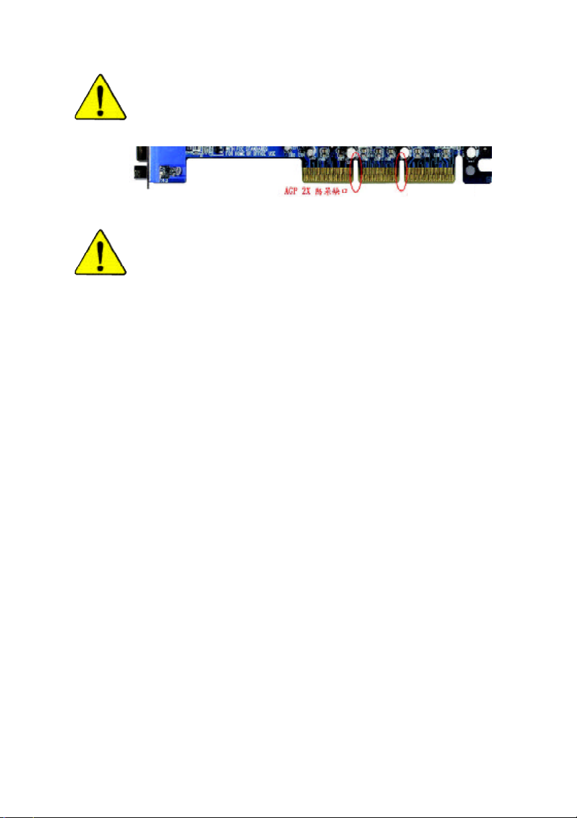
當您安裝AGP 卡時,請注意下述注意事項。
您的顯示卡若有AGP 4X/8X 防呆缺口(如下圖),請再次確
認此卡的規格為AGP 4X/ 8X(1.5V)。
AGP 4X/8X 防呆缺口
不要使用AGP 2X 卡,因為VIA® KM400A晶片組不支援
AGP 2X(3.3V),若您使用 AGP 2X (3.3V)卡時,可能造成系統
無法正常開機的情況,所以請使用AGP 4X/8X(1.5V)卡。
範例一:Diamond Vipper V770 這塊顯示卡的金手指部份設計成
2X/4X插槽皆可使用,透過Jumper 可切換於 2X 或 4X ,出廠預
設值為2X(3.3V),若您使用此卡在 GA-7VM 400AM(F)主機板
上,而且沒有將Jumper 切換至4X (1.5V)的模式時,可能造成
系統無法正常開機的情況。
範例二:某些SiS 305及Power Color所生產的某些ATi Rage 128
Pro 等顯示卡的金手指部份設計成 2X/4X插槽皆可使用,但只
支援2X(3.3V),若您使用此卡在GA-7VM400AM(F)主機板上,
可能造成系統無法正常開機的情況。
注意:技嘉科技所生產的AG32S(G)顯示卡,雖然採用ATi
Rage 128 Pro 晶片,但此卡設計符合 AGP4X(1.5V)的規格,因
此不會發生如範例二中可能造成系統無法正常開機的情況,
請您安心使用。
Page 2
本手冊所有提及之商標與名稱皆屬該公司所有。
在科技迅速的發展下,此發行手冊中的一些規格可能會
有過時不適用的敘述,敬請見諒。
在此不擔保本手冊無任何疏忽或錯誤亦不排除會再更新
發行。手冊若有任何內容修改,恕不另行通知。
主機板上的任何貼紙請勿自行撕毀,否則會影響
到產品保固期限的認定標準。
Page 3

Declaration of Conformity
G.B.T. Technology Träding GMbH
Ausschlager Weg 41, 1F, 20537 Hamburg, Germany
( description of the apparatus, system, installation to which it refers)
(reference to the specification under which conformity is declared)
in accordance with 89/336 EEC-EMC Directive
o EN 55011 Limits and methods of measurement
o EN 55013
o EN 55014 Limits and methods of measurement
o EN 55015 Limits and methods of measurement
o EN 55020
T EN 55022 Limits and methods of measurement
o DIN VDE 0855
o p art 10
o p art 12
T CE ma rking
o EN 60065
o EN 60335
of radio disturbance characteristics of
industrial,scientific and medic al (ISM
high frequency equipment
Limits and methods of measurement
of radio disturbance characteristics of
broadcast receivers and associated
equipment
of radio disturbance characteristics of
household electrical appliances,
portable tools and similar electrical
apparatus
of radio disturbance characteristics of
fluorescent lamps and luminaries
Immunity from radio interference of
broadcast receivers and associated
equipment
of radio disturbance characteristics of
information technology equipment
Cabled distribution systems; Equipment
for rece iving and/or distribution from
sound and television signals
The manufacturer also declares the conformity of above mentioned product
with the actual r equired safety standards in accordance with LVD 73/23 EEC
Safety requirements for mains operated
electronic and related apparatus for
household and similar general use
Safety of household and similar
electrical appliances
(S tamp)
We, Manufacturer/Importer
(full address)
declare that the product
Mother Board
GA-7VM400AM(F)
is in conformity with
o EN 61000- 3-2*
T EN 60555-2
o EN 61000- 3-3* Disturbances in supply systems cause
T EN 60555-3
T EN 50081-1
T EN 50082-1
o EN 55081-2
o EN 55082-2
o ENV 55104
o EN5009 1-2
o EN 60950
o EN 50091-1
Manufa cturer/Importer
Date : December 22, 2003
Disturbances in supply systems cause
by household appliances and similar
electrical equipment “Harmonics”
by household appliances and similar
electrical equipment “Voltage fluctuations”
Generic emission standard Part 1:
Residual commercial and light industry
Generic immunity standard Part 1:
Residual commercial and light industry
Generic emission standard Part 2:
Industrial environment
Generic emission standard Part 2:
Industrial environment
lmmunity requirements for household
appliances tools and similar apparatus
EMC requirements for uninte rruptible
powe r systems (UPS)
(EC confor mity marking)
Safety for information technology equipment
including electrical bussiness equipment
General and Safety requir ments for
uninterruptible power systems (UPS)
Signature:
Name:
Timmy Huang
Timmy Huang
Page 4

DECLA RATION OF CONFORMITY
Per FCC Part 2 Section 2.1077(a)
Resp onsible PartName:
Add ress:
Ph one/Fax No:
hereby declares that the product
Produ ct Name:
Model Number:
Conforms to the following specifications:
FCC Part 15, Subpart B, Section 15.107(a) and Section 15.109(a),
Class B Digital Device
Su pplementary Information:
This device complies with part 15 of the FCC Rules. Operation is
subject to the following two conditions: (1) This device may not
cause harmful and (2) this device must accept any inference received,
including that may cause undesired operation.
Representative Person’s Name:
Signature:
G.B.T. INC . (U.S.A.)
17358 Railroad Street
City of Industry, CA 91748
(818) 854-9338/ (818) 854-9339
Moth erboard
GA-7VM400AM(F)
ERIC LU
Eric Lu
Date:
December 22 ,2003
Page 5

7VM400AM(F)
AMD Socket A
AMD AthlonTM / AthlonTM XP/ Duron
Rev. 1003
12MC-7VM400AM-1003
TM
Socket A
Page 6
............................................................................ 4
....................................................................... 5
.............................................................................................................. 5
GA-7VM400AM(F) Layout .................................................................... 7
............................................................................... 8
.................................................. 10
1 Switch (SW1) ...................................................................... 11
2 (CPU) ................................................................... 12
2-1 ................................................................................. 12
2-2 ................................................................ 13
3 ............................................................................. 14
4 ...................................................................................... 16
5: ............ 17
5-1 I/O ........................................................................... 17
5-2 ................................................................................................... 19
BIOS .................................................. 31
(BIOS E4) .................................................. 32
CMOS ................................................................................... 34
BIOS ............................................................................ 37
....................................................................................... 39
....................................................................................... 43
- 2 -GA-7VM400AM(F)
Page 7
PCI ................................................................ 45
....................................................................................... 46
/ .................................................................................... 47
Fail-Safe ........................................................................... 49
Optimized ......................................................................... 50
(Supervisor)/ (User) ................................... 51
SETUP .......................................................... 52
SETUP ..................................................... 53
......................................... 57
Easy TuneTM 4 ................................................................................. 57
@ BIOS
BIOS
Jack-Sensing
Xpress Recovery
Serial ATA RAID BIOS
TM
........................................................................................ 58
............................................................................. 59
/ / ................................................ 74
......................................................................... 80
............................................................................. 82
......................................... 85
..................................................................... 93
- 3 -
Page 8
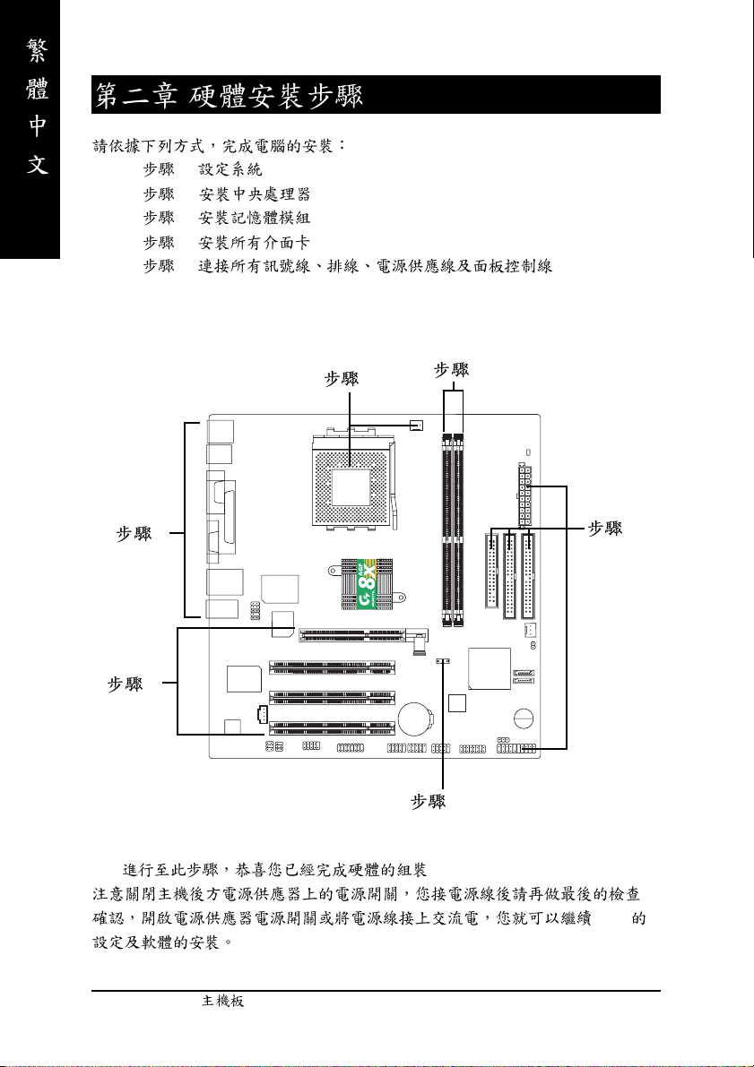
1.
2.
3. (CPU RAM)
4.
5. ATX
PCB
- 4 -GA-7VM400AM(F)
Page 9
z Micro ATX 24.4 x 23.3
z AMD AthlonTM / AthlonTM XP / DuronTM (K7) Socket A
128K 512K/256K/64K
CPU 200/266/333/400 MHz FSB
z
z VIA KM400A Memory/AGP/PCI
z VT8237
z 2 184-pin DDR DIMM
z DDR400DDR333/DDR266/DDR200 DIMM
z 2GB DDR
z
I/O z IT8705
z 1 AGP , 8X/4X/2X (1.5V)
z 3 PCI
IDE z 2 IDE bus master (UDMA 33/ATA 66/ATA 100/ATA133) IDE
z PIO mode 3 4(UDMA33/ATA66/ATA100/ATA133) IDE
SATA z 2 Serial ATA
z CPU /
z CPU /
z CPU /
z
z 1 (360K, 720K, 1.2M, 1.44M
z 1
z 1 (COMA) 1 VGA COMB
z
z 3
z 1
1.4 GHz
2.5V DDR DIMM
33MHz PCI2.2 compliant
4 ATAPI
ATAPI CD-ROM
( 1)
2.88M bytes)
8 USB 2.0/1.1
(
x 4 x 4)
IEEE1394 ( ) (*
Normal/EPP/ECP
)
( 1) SATA 1.5 Gb/s
(*)
GA-7VM400AMF
.......
- 5 -
Page 10
SATA RAID z VT8237
z
z
Disk striping (RAID0) DISK Mirroring (RAID1)
UDMA up to 150 MB/sec
z 2 SATA
z CODEC (RealTek ALC655)
z Jack-Sensing
z Line Out : 2
z Line In : 2 ( )
z Mic In : / ( )
z SPDIF Out/SPDIF In
z CD_In / Game Connector
USB2.0 z VIA VT8237
z RTL8100C (10/100 Mbit)
z 1 RJ45
IEEE1394 (*
)
z Ti TSB43AB23
PS/2 z PS/2 PS/2
BIOS z Award BIOS
z Q-Flash
z PS/2 PS/2
z
z STR (Suspend-To-RAM)
z AC Recovery
z
z USB / S3
z Thermal shutdown
z @BIOS
TM
z Easy Tune 4
z (DDR/CPU)
z (DDR/AGP)
(*)
CPU CPU
CPU
GA-7VM400AMF
- 6 -GA-7VM400AM(F)
Page 11
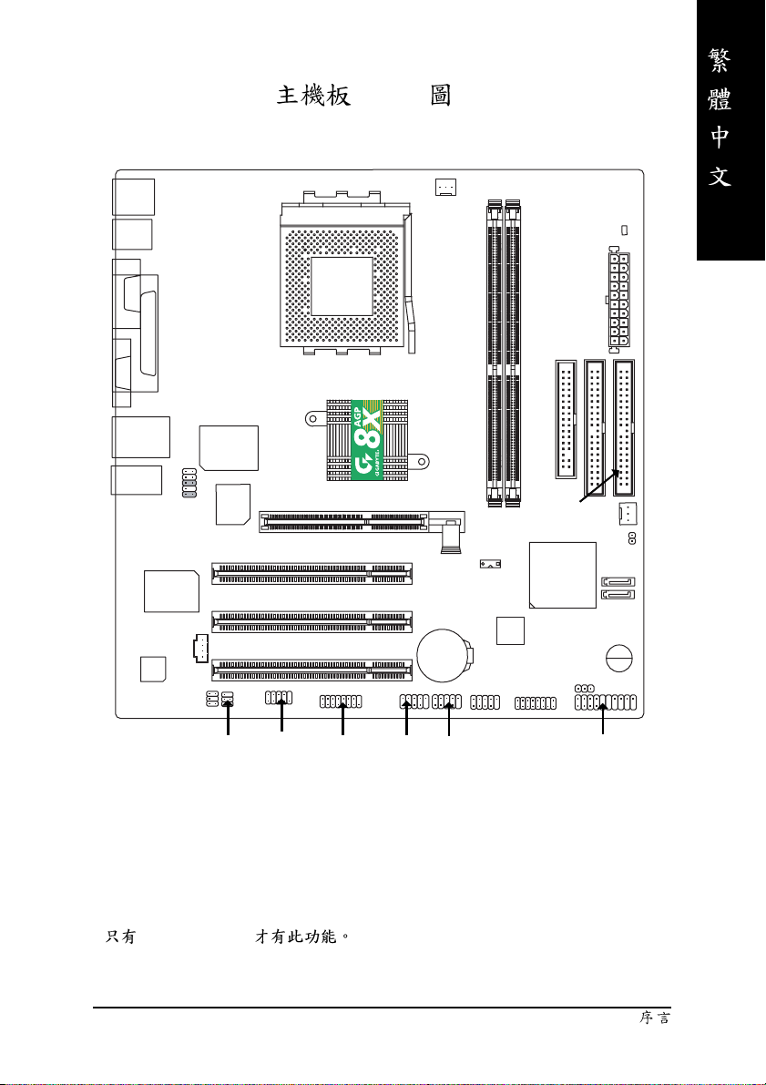
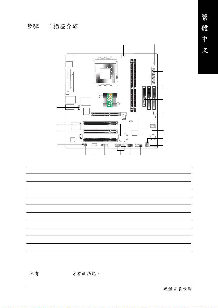
GA-7VM400AM(F) Layout
KB_MS
USB
COMA
VGA
USB
MIC_IN
LPT
LINE_OUT
RTL8100C
CODEC
LAN
LINE_IN
F_AUDIO
SUR_CEN
IT8705
BIOS
CD_IN
AGP 8X
SOCKET A
VIA KM400A
PCI3
PCI1
PCI2
CPU_FAN
GA-7VM400AM(F)
AGP
SW1
TSB43AB23 (*
BAT
F1_1394 (*
DDR1
DDR2
)
F2_1394 (*
FDD
IDE2
VT8237
)
RAM_LED
ATX
IDE1
SYS_FAN
CLR_CMOS
PWR_LED
)
SATA1
SATA0
BZ
(*)
SPDIF_IO
GA-7VM400AMF
COMB
GAME
- 7 -
F_USB1
F_USB2
F_PANEL
Page 12
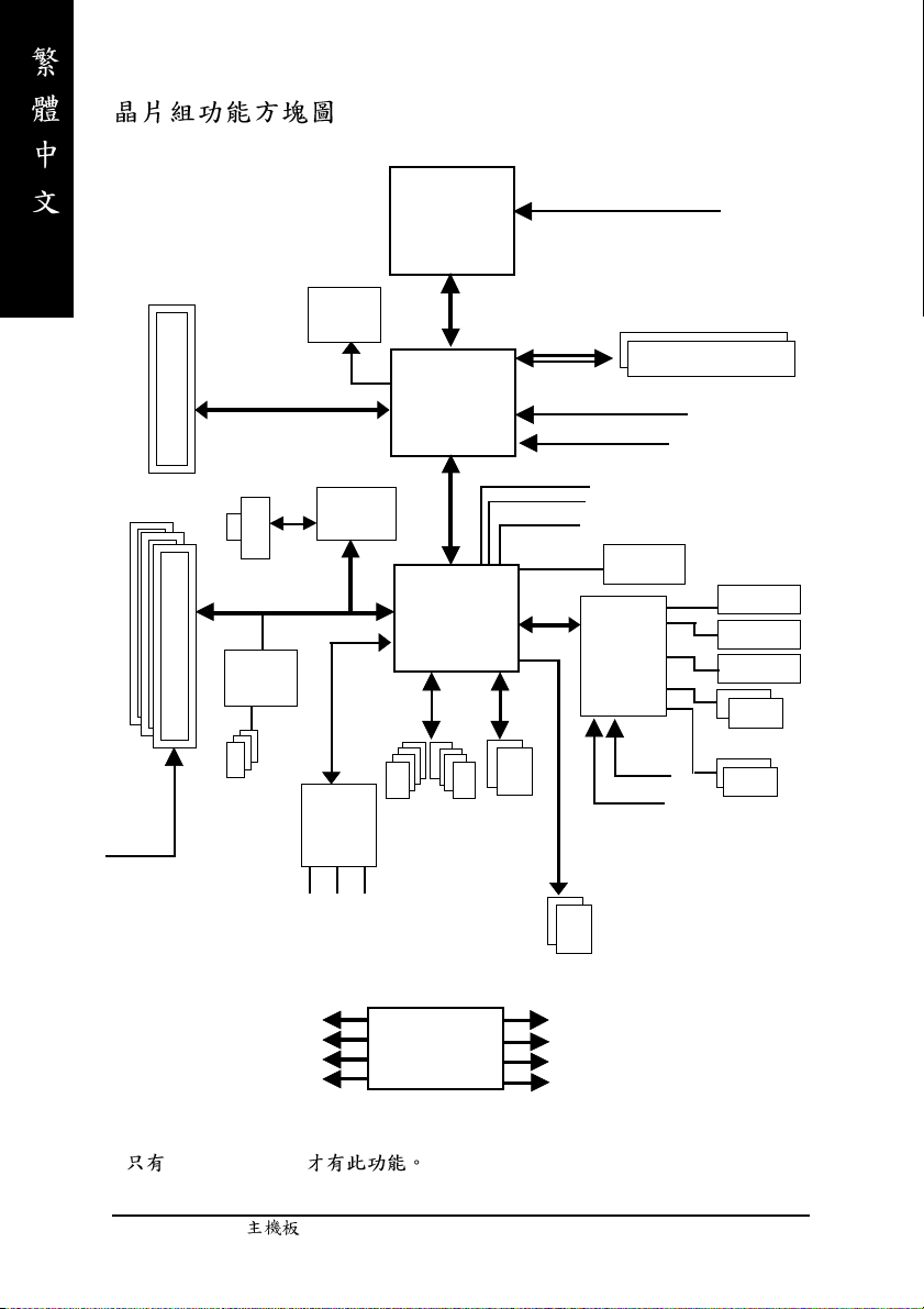
AMD-K7
Host CUP
TM
CPUCLK+/- (100/133/166/200MHz)
AGP 2X/4X/8X
3 PCI
PCICLK
(33MHz)
AGPCLK
RJ45
PCI BUS 33MHz
TSB43AB23 (*
IEEE1394 (*
66MHz
)
VGA Port
RTL8100C
)
AC97 Link
6 Channel
CODEC
MIC
LINE-IN
KM400A
8 USB
Ports
LINE-OUT
System Bus
200/266/333/400MHz FSB
VIA
66MHz V_Link
VIA
VT8237
ATA33/66/
100/133
IDE Channels
200/266/333/400MHz
DDR
HCLK+/- (100/133/166/200MHz)
AGPCLK66 MHz
33 MHz
48 MHz
14.318 MHz
BIOS
LPC BUS
IT8705
24 MHz
33 MHz
Serial ATA
Channels
Game Port
Floppy
LPT Port
PS/2 KB/Mouse
2 COM Ports
(*)
PCICLK (33MHz)
USBCLK (48MHz)
14.318 MHz
33 MHz
GA-7VM400AMF
CLK
GEN
HCLK+/- (100/133/166/200MHz)
CPUCLK+/- (100/133/166/200MHz)
AGPCLK (66MHz)
V_Link (66MHz)
- 8 -GA-7VM400AM(F)
Page 13

- 9 -
Page 14
1 - Switch (SW1)
2 - (CPU)
3 -
4 -
5 -
4
5
2
3
5
1
!!
BIOS
- 10 -GA-7VM400AM(F)
Page 15
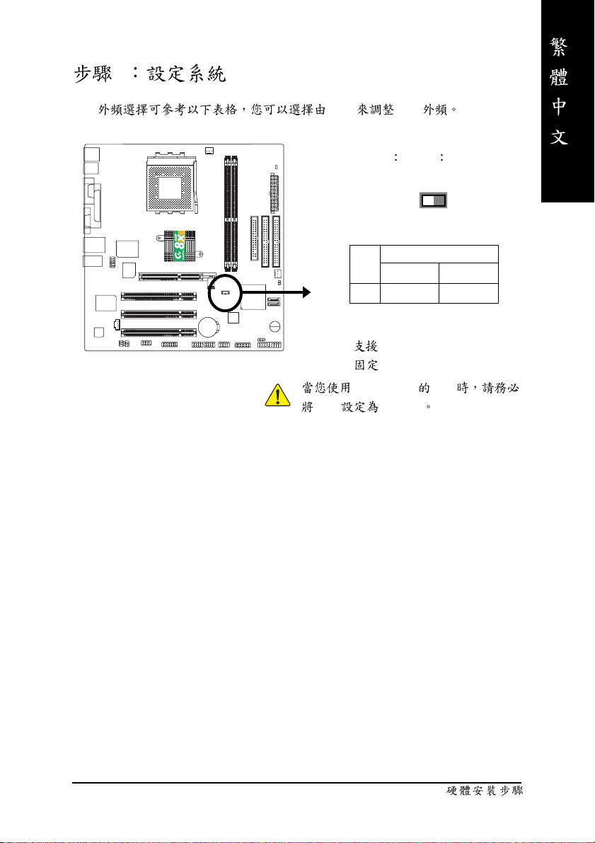
1 Switch (SW1)
CPU SW1 CPU
O ON / X OFF
ON
SW1 CPU CLOCK
100 AUTO
1 O N OFF
Auto : FSB 266/333/400 MHz CPU
100MHz :
SW1 100MHz
FSB 200MHz CPU
FSB 200MHz CPU
SW1
1
- 11 -
Page 16
2 (CPU)
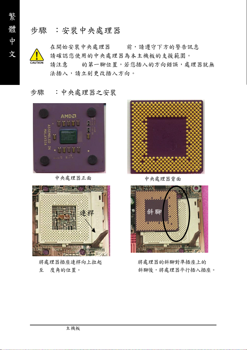
(CPU) :
CPU
2-1
1.
90
2.
- 12 -GA-7VM400AM(F)
Page 17
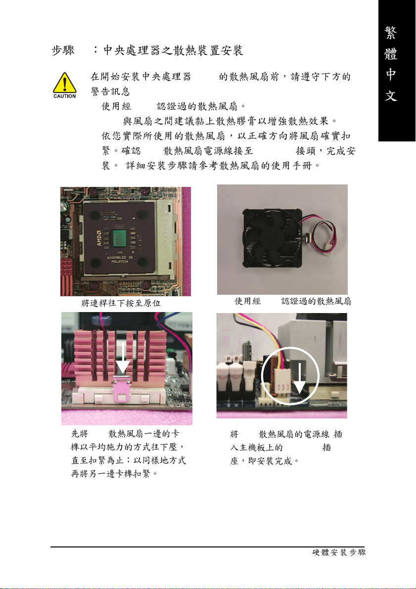
2-2
1. AMD
2. CPU
3.
(CPU)
:
CPU CPU FAN
( )
1.
3. CPU
2. AMD
4. CPU
CPU_FAN
- 13 -
Page 18
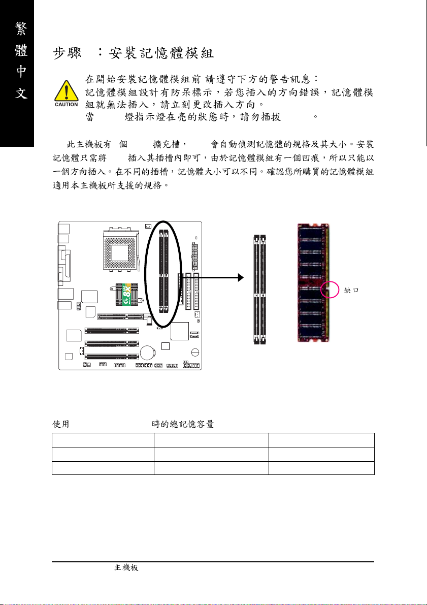
3
,
DIMM DIMM
2 (DIMM) BIOS
DIMM
DDR
Unbuffered DDR DIMM
64 Mbit (2Mx8x4 banks) 64 Mbit (1Mx16x4 banks) 128 Mbit(4Mx8x4 banks)
128 Mbit(2Mx16x4 banks) 256 Mbit(8Mx8x4 banks) 256 Mbit(4Mx16x4 banks)
512 Mbit(16Mx8x4 banks) 512 Mbit(8Mx16x4 banks)
- 14 -GA-7VM400AM(F)
Page 19
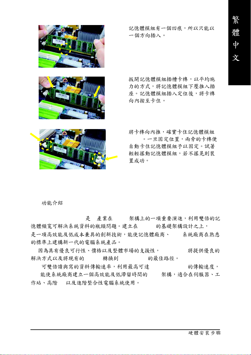
1.
2.
3.
DIMM
DDR
DDR(Double Data Rate) PC SDRAM
SDRAM DDR
OEM
DDR SDRAM
SDRAM DDR SDRAM
DDR 3.2GB/s(DDR400)
DDR DRAM
PC
- 15 -
Page 20
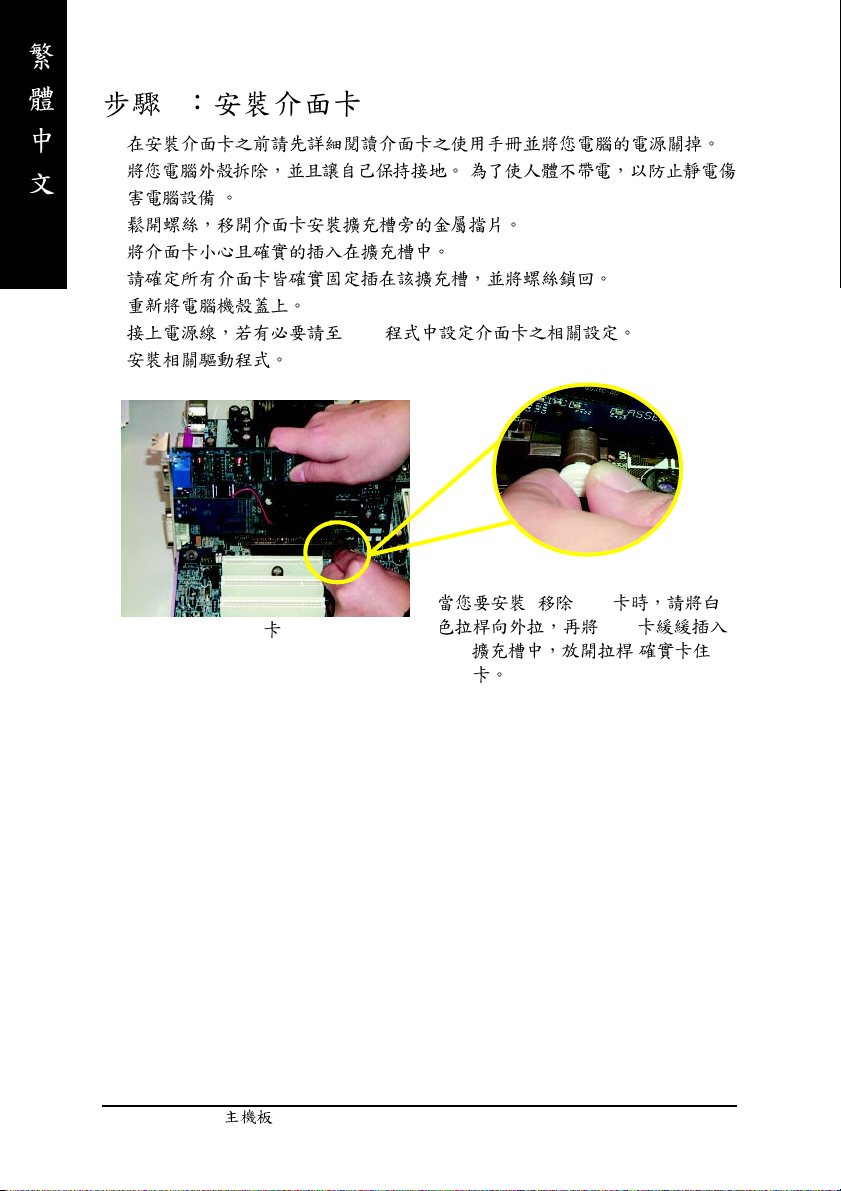
4
1.
2. (
)
3.
4.
5.
6.
7. BIOS
8.
AGP
AGP
AGP
/ AGP
AGP
- 16 -GA-7VM400AM(F)
Page 21
5:
5-1 I/O
X
Y
X PS/2 PS/2
PS/2
(6 pin Female)
PS/2
(6 pin Female)
Y/[ ,
USB 7 (
USB 6 ( 6)
LAN ( )
Z[
\
PS/2
PS/2
10/100Mbps
7)
USB USB USB
USB ZIP USB .
USB 5 ( 5)
USB 4 ( 4)
USB
- 17 -
Page 22
Z COMA( A)/VGA( )/LPT( )
(25 pin Female)
A
(15 pin Female)
(9 pin Male)
\
Line In (Rear Speaker)
Line Out (Front Speaker)
MIC In (Center and Subwoofer)
2-/4-/6- 74
2-/4-/6-
6-channel
2
:
"Line Out"
"Line In"
"Mic In"
:
P.25
SUR_CEN
- 18 -GA-7VM400AM(F)
Page 23
5-2
1
10
9
12
11
13
16
15
)
17(*
14
1) CPU_FAN 12) CD_IN
2) SYS_FAN 13) SPDIF_IO
3) ATX 14) F_USB1/F_USB2
4) IDE1/IDE2 15) COMB
5) FDD 16) GAME
6) RAM_LED 17) F1_1394 (*
7) F_PANEL 18) F2_1394 (*
)
)
8) PWR_LED 19) SATA0/SATA1
9) BAT 20) CLR_CMOS
10) F_AUDIO
11) SUR_CEN
18(*
6
3
4
5
2
20
19
8
7
)
(*)
GA-7VM400AMF
- 19 -
Page 24
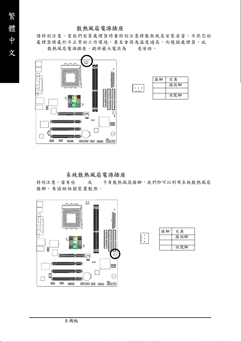
1) CPU_FAN (CPU )
CPU 600
2) SYS_FAN ( )
AGP PCI
1
1
2 +12V
3
1
1
2 +12V
3
- 20 -GA-7VM400AM(F)
Page 25
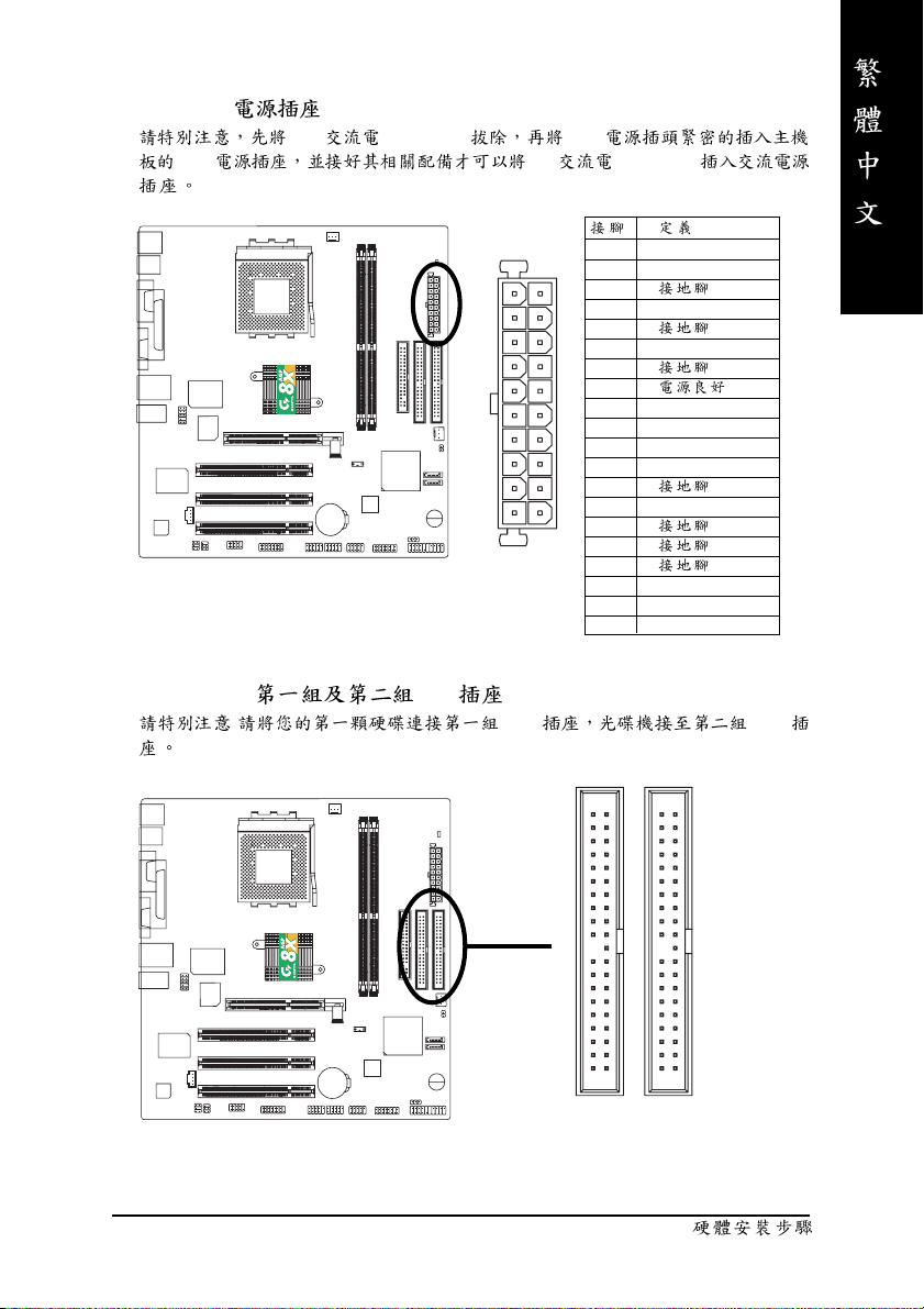
3) ATX (ATX )
AC (110/220V) ATX
ATX AC (110/220V)
11
20
4) IDE1/ IDE2( IDE )
: IDE IDE
1 3.3V
2 3.3V
3
1
4 VCC
5
6 VCC
7
8
9 5V SB(stand by +5V)
10 +12V
11 3.3V
12 -12V
13
14 PS_ON(softOn/Off)
10
15
16
17
18 -5V
19 VCC
20 VCC
- 21 -
40
2
IDE1
39
1
IDE2
Page 26
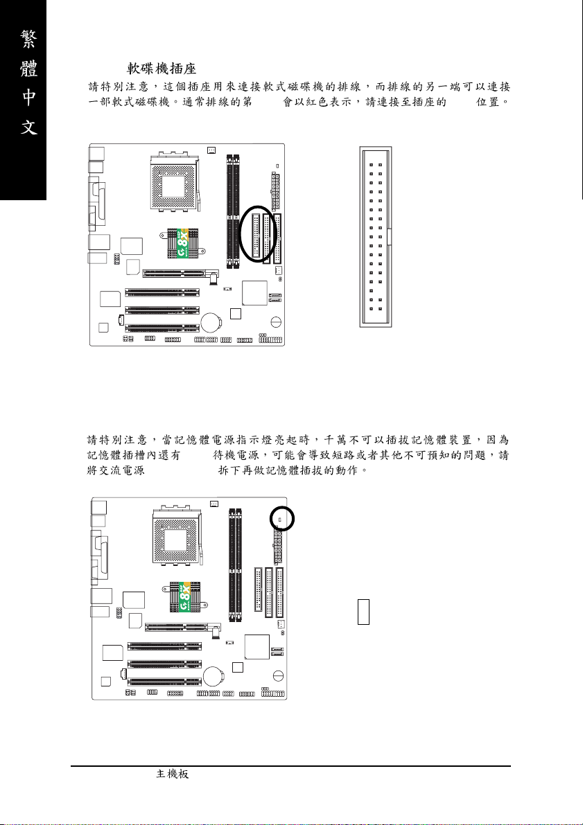
5) FDD ( )
1Pin Pin1
6) RAM_LED
2.5V
(AC110/220V)
34
2
33
1
+
-
- 22 -GA-7VM400AM(F)
Page 27
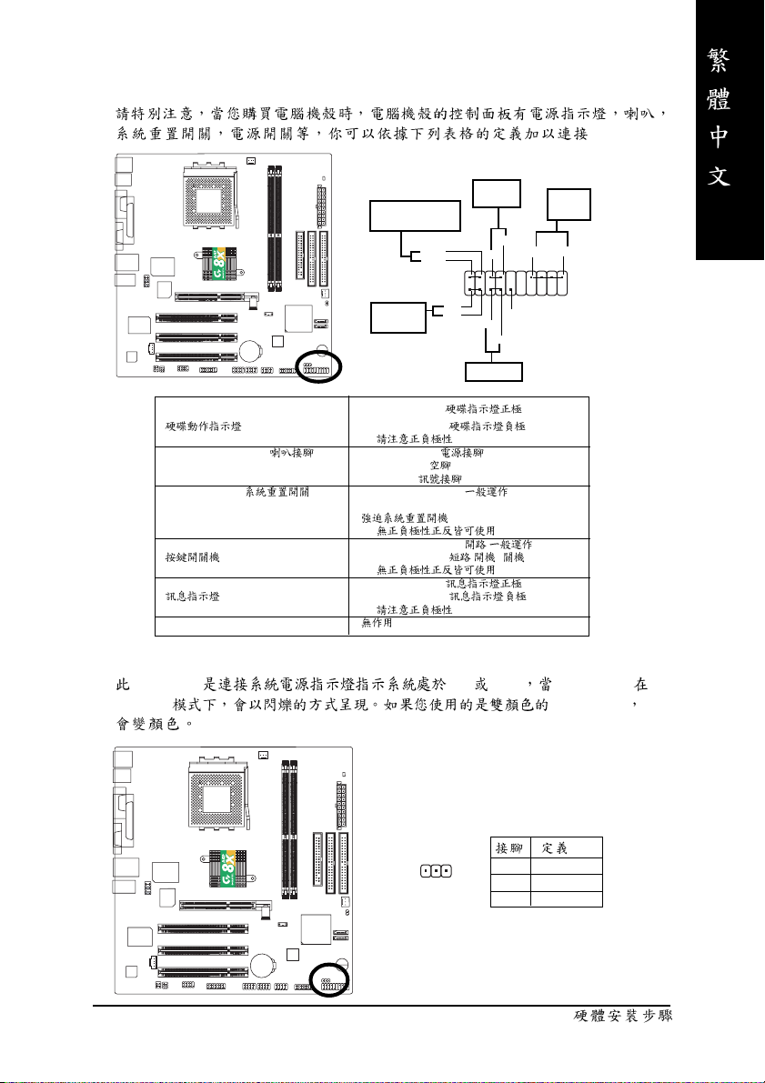
7) F_PANEL (2x10 pins connector)
.
Message LED/Power/
Sleep LED
MSG-
MSG+
IDE Hard Disk
Active LED
HD+
HD-
Soft Power
Connector
2
1
1
1
Reset Switch
PW+
1
RES-
RES+
PW-
Speaker
Connector
SPK-
SPK+
20
1
1
NC
19
HD (IDE Hard Disk Active LED) Pin 1: LED anode(+)
Pin 2: LED cathode(-)
SPK (Speaker Connector) Pin 1: VCC(+) +5v
RES (Reset Switch) Open: Normal Operation
PW (Soft Power Connector) Open: Normal Operation :
MSG(Message LED/Power/Sleep LED) Pin 1: LED anode(+)
NC
0
Pin 2- Pin 3: NC
Pin 4: Data(-)
Close: Reset Hardware System
0
Close: Power On/Off : /
0
Pin 2: LED cathode(-)
0
8) PWR_LED
PWR_LED ON OFF Power LED
Suspend power LED LED
- 23 -
1
1 MPD+
2 MPD3 MPD-
Page 28
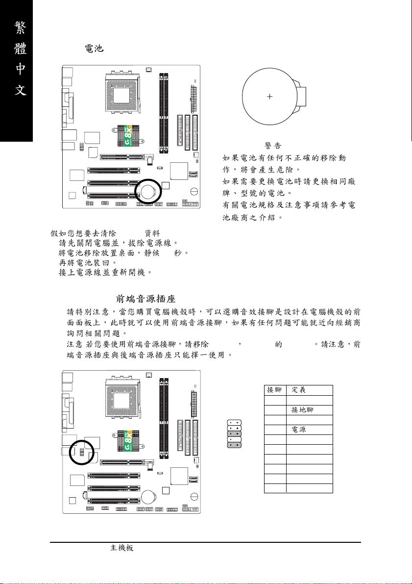
9) BAT( )
+
1.
CMOS ...
2. 30
3.
4.
10) F_AUDIO ( )
: Pin5-6 Pin9-10 Jumper
12
109
1 MIC
2
3 REF
4
5 FrontAudio(R)
6 RearAudio(R)
7 Reserved
8 No Pin
9 FrontAudio (L)
10 RearAudio(L)
- 24 -GA-7VM400AM(F)
Page 29
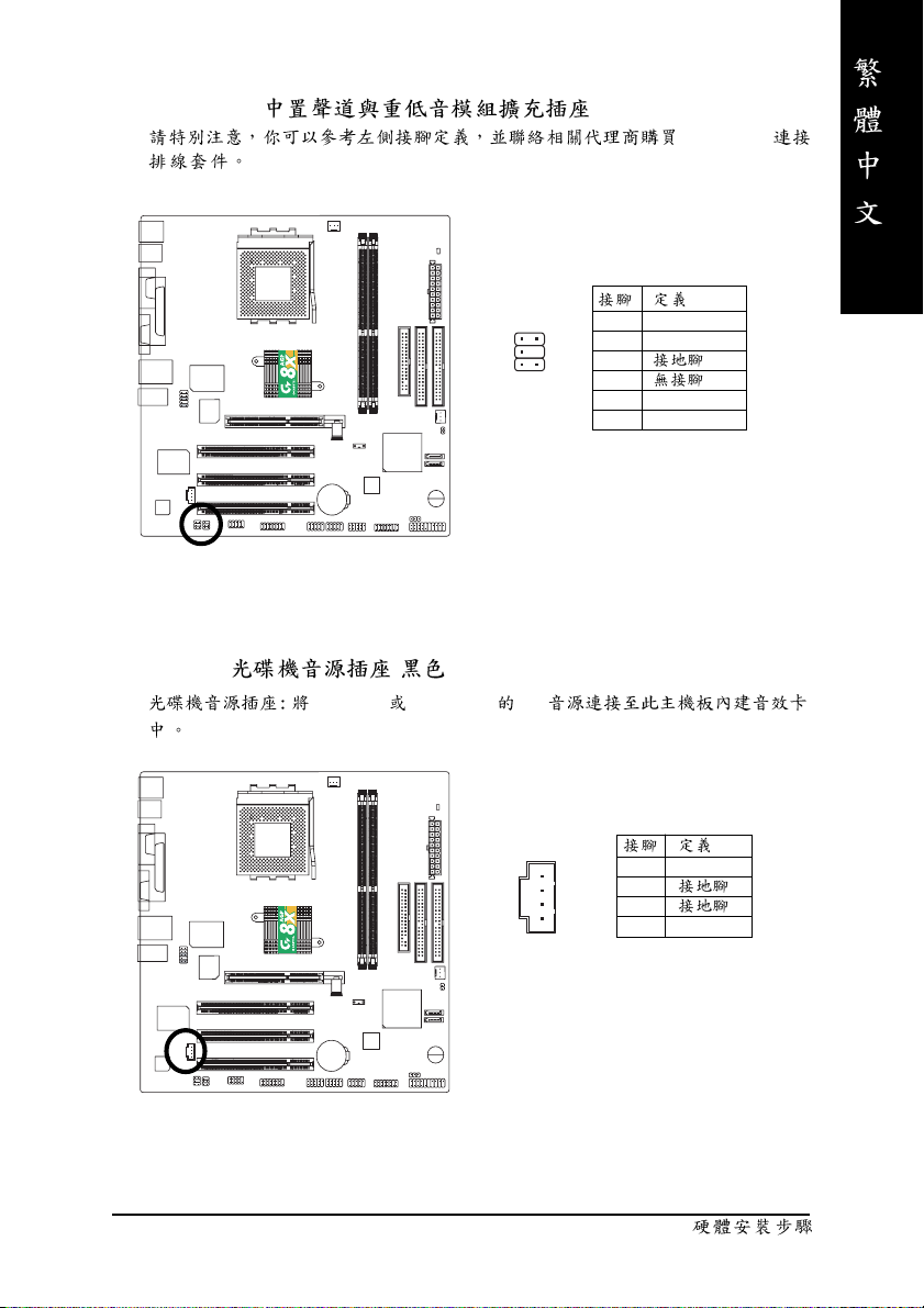
11) SUR_CEN( )
2
1
5
6
12) CD_IN ( , )
CD-ROM DVD-ROM CD
SUR_CEN
1 SUR OUTL
2 SUR OUTR
3
4
5 CENTER_OUT
6 BASS_OUT
- 25 -
1
1 CD-L
2
3
4 CD_R
Page 30
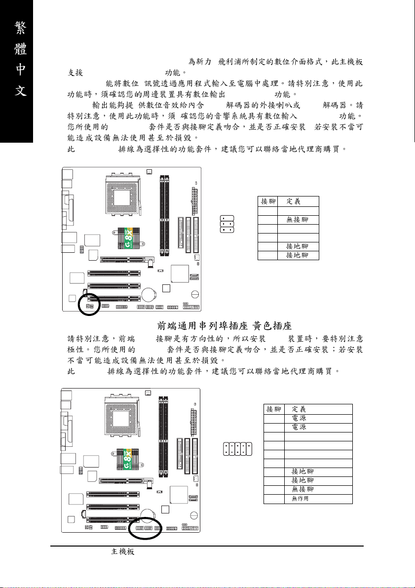
13) SPDIF_IO (SPDIF In/Out)
Sony/Philip Digital Interface Format /
SPDIF IN & SPDIF OUT
SPDIF IN
(SPDIF Out)
SPDIF AC-3 AC-3
(SPDIF In)
SPDIF_IO ;
SPDIF_IO
2
1
6
5
1 VCC
2
3 SPDIF
4 SPDIFI
5
6
14) F_ USB1 / F_USB2( , )
USB USB
F_USB
F_USB
1
2
2
1
3 USB0 DX-/USB2 DX-
10
4 USB1 Dy-/USB3 Dy5 USB0 DX+/USB2 DX+
9
6 USB1 Dy+/USB3 Dy+
7
8
9
10
- 26 -GA-7VM400AM(F)
Page 31

15) COMB ( B)( )
B B
B
16) GAME ( )
1 NDCDB2 NSINB
2
10
9
1
3 NSOUTB
4 NDTRB5
6 NDSRB7 NRTSB8 NCTSB9 NRIB10
2
16
115
- 27 -
1
2 GRX1_R
3
4 GPSA2
5
6 GPX2_R
7 GPY2_R
8 MSI_R
9 GPSA1
10
11 GPY1_R
12
13 GPSB1
14 MSO_R
15 GPSB2
16
Page 32

17) F1_1394 (IEEE 1394 Connector) (*
1394 IEEE1394
(Insitute of Electrical Eletronics Engineers)
IEEE1394
IEEE1394
)
1 TPA2+
2 TPA2-
2
10
1
9
3
4
5 TPB2+
6 TPB27
8
9
10
18) F2_1394 (IEEE 1394 Connector) (*
1394 IEEE1394
(Insitute of Electrical Eletronics Engineers)
IEEE1394
IEEE1394
(*)
GA-7VM400AMF
)
1
2
2
16
1
3 TPA0+
4 TPA05
6
15
7 TPB0+
8 TPB09
10
11 TPA1+
12 TPA113
14
15 TPB1+
16 TPB1-
- 28 -GA-7VM400AM(F)
Page 33

19) SATA0/SATA1 (Serial ATA )
Serial ATA 150MB Serial ATA
71
20) CLR_CMOS ( CMOS )
CMOS
Clear CMOS 1-2Pin
1
2 TXP
3 TXN
4
5 RXN
6 RXP
7
- 29 -
1
1
CMOS
Page 34

- 30 -GA-7VM400AM(F)
Page 35

繁
第三章BIOS 組態設定
基本上主機板所附Award BIOS 便包含了CMOS SETUP程式,以供使用者自行依照
需求,設定不同的數據,使電腦正常工作,或執行特定的功能。
CMOS SETUP會將各項數據儲存於主機板上內建的CMOS SRAM中,當電源關閉時,
則由主機板上的鋰電池繼續供應CMOS SRAM 所需電力。
當電源開啟之後,BIOS開始進行POST(Power On Self Test 開機自我測試)時,按
下<Del>鍵便可進入Aw ard BIOS的 CMOS SETUP主畫面中。如果您需要進階的
BIOS設定,當您在BIOS 設定畫面時按下"Ctrl+F1" 即可進入。
操作按鍵說明
h 移到上一個項目
i 移到下一個項目
f 移到左邊的項目
g 移到右邊的項目
Enter 確定選項
Esc 回到主畫面,或從主畫面中結束 SETUP程式
Page Up 改變設定狀態,或增加欄位中之數值內容
Page Down 改變設定狀態,或減少欄位中之數值內容
F1 顯示所有功能鍵的相關說明
F2 可顯示目前設定項目的相關說明
F3 功能保留
F4 功能保留
F5 可載入該畫面原先所有項目設定(但不適用主畫面)
F6 可載入該畫面之Fail-Safe 預設設定(但不適用主畫面)
F7 可載入該畫面之Optimized 預設設定(但不適用主畫面)
F8 Q-Flash功能
F9 系統資訊
F10 儲存設定並離開CMOS SETUP 程式
體
中
文
- 31 -
BIOS組態設定
Page 36

繁
體
中
文
如何使用輔助說明
主畫面的輔助說明
當您在SETUP 主畫面時,隨著選項的移動,底下便跟著顯示︰目前被選到的
SETUP項目的主要設定內容。
設定畫面的輔助說明
當您在設定各個欄位的內容時,只要按下<F1 >,便可得到該欄位的設定預設值
及所有可以的設定值,如BIOS預設值或 CMOS SETUP 預設值,若欲跳離輔助說明
視窗,只須按<Esc>鍵即可。
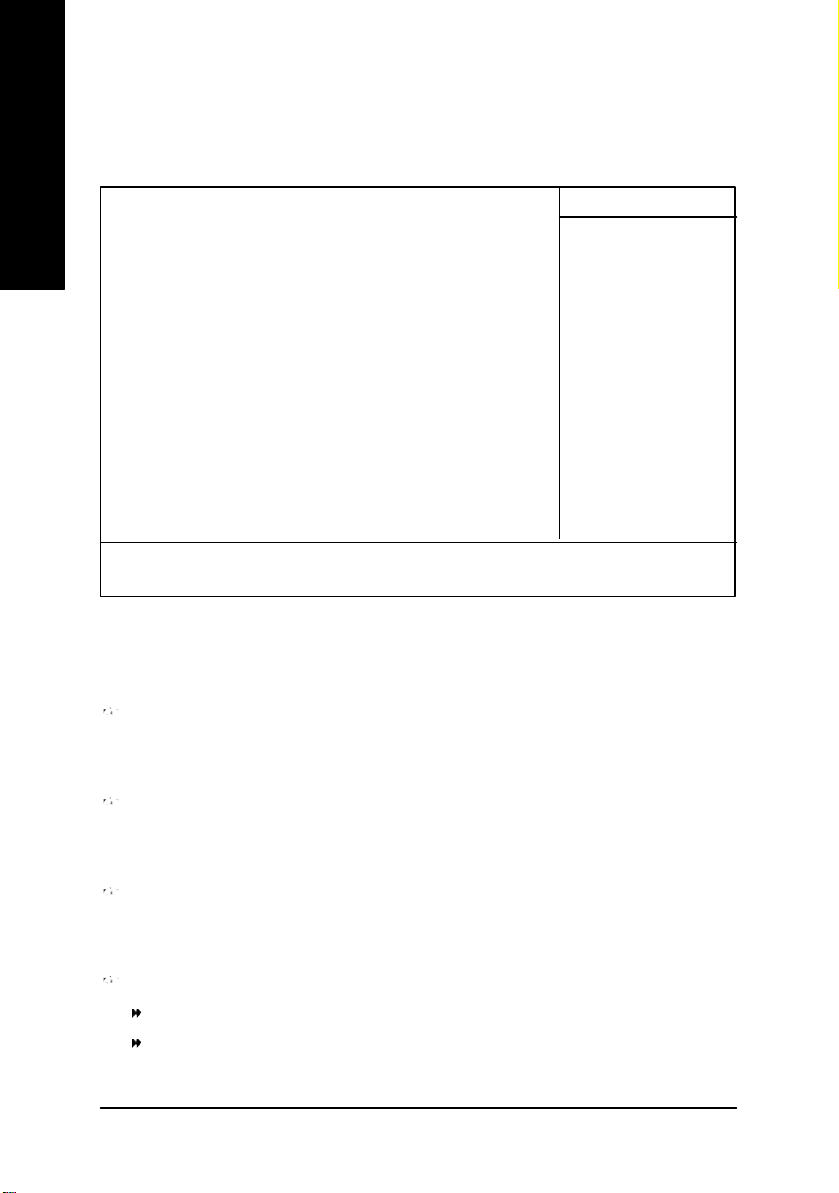
主畫面功能 (BIOS 範例版本:E4)
當您進入CMOS SETUP 設定畫面時,便可看到如下之主畫面,從主畫面中可以讓你
選擇各種不同之設定選單,你可以用上下左右鍵來選擇你要設定之選項並按Enter
進入子選單。
CMOS Setup Utility-Copyright (C) 1984-2003 Award Softw are
}Standard CMOS Features Load Fail-Safe Defaults
}Adv anced BIOS Features Load Optimized Defaults
}Integrated Peripherals Set Superv isor Password
}Pow er Management Setup Set User Password
}PnP/PCI Configurations Sav e & Exit Setup
}PC Health Status Exit Without Saving
}Frequency /Voltage Control
ESC:Quit higf: Select Item
F8:Q-Flash F10:Sav e & Exit Setup
Time, Date, Hard Disk Type...
圖 1: 主畫面功能
若在主畫面功能選項中,沒有找到您所需要的選項設定,請按
"Ctrl+F1"進入進階 BIOS畫面設定,作進一步搜尋。
l Standard CMOS Features (標準 CMOS 設定)
設定日期、時間、軟硬碟規格、及顯示器種類。
l Advanced BIOS features (進階 BIOS 功能設定)
設定BIOS提供的特殊功能,例如病毒警告、開機磁碟優先順序、磁碟代號交
換....等。
- 32 -GA-7VM400AM(F)主機板
Page 37

l Integrated peripherals (整合週邊設定)
在此設定畫面包括所有週邊設備的的設定。如COM Port 使用的IRQ 位址,LPT
Port 使用的模式SPP、 EPP或 ECP以及IDE 介面使用何種PIO Mode...等。
l Power management setup (省電功能設定)
設定CPU 、硬碟、GREEN 螢幕等裝置的省電功能運作方式。
l PnP/PCI configur ation (隨插即用與 PCI組態設定)
設定ISA之 PnP即插即用介面以及 PCI介面的相關參數。
l PC Health Status (電腦健康狀態)
系統自動偵測電壓,溫度及風扇轉速等。
l Frequency/Voltage Control (頻率 / 電壓控制)
設定控制CPU 時脈及倍頻調整。
l Load Fail-Safe defaults (載入 Fail-Safe預設值)
執行此功能可載入BIOS的CMOS 設定預設值,此設定是比較保守,但較能進
入開機狀態的設定值。
l Load Optimized defaults (載入 Optimized 預設值)
執行此功能可載入Optimized的CMOS設定預設值,此設定是較能發揮主機板速
度的設定。
l Set Supervi sor password (管理者的密碼)
設定一個密碼,並適用於進入系統或進入SETUP修改 CMOS 設定。
l Set User p assw ord (使用者密碼)
設定一個密碼,並適用於開機使用PC 及進入 BIOS修改設定 。
l Save & exit setup (儲存並結束)
儲存所有設定結果並離開SETUP程式,此時BIOS會重新開機,以便使用新的
設定值,按<F10>亦可執行本選項。
l Exit without save (結束 SETU P程式)
不儲存修改結果,保持舊有設定重新開機,按<ESC>亦可直接執行本選項。
繁
體
中
文
- 33 -
BIOS組態設定
Page 38

繁
體
中
文
標準 CMOS 設定
CMOS Setup Utility-Copyright (C) 1984-2003 Award Softw are
Standard CMOS Features
Date (mm:dd:yy ) Tue, Aug 13 2002 Item Help
Time (hh:mm:ss) 22:31:24 Menu Level u
Change the day , month,
}IDE Primary Master [None] y ear
}IDE Primary Slav e [None]
}IDE Secondary Master [None] <Week>
}IDE Secondary Slav e [None] Sun. to Sat.
Driv e A [1.44M, 3.5 in.] <Month>
Driv e B [None] Jan. to Dec.
Floppy 3 Mode Support [Disabled]
<Day >
Halt On [All, But Key board] 1 to 31 (or max imum
allow ed in the month)
Base Memory 640K
Ex tended Memory 130048K <Year>
Total Memory 131072K 1999 to 2098
higf: Mov e Enter:Select +/-/PU/PD:Value F10:Sav e ESC:Exit F1:General Help
F5:Prev ious Values F6:Fail-Safe Defaults F7:Optimized Defaults
圖 2: 標準 CMOS 設定
Date(mm:dd:yy) (日期設定)
即設定電腦中的日期,格式為「星期,月/日 /年」,各欄位設定範圍如下
表示:
星期 由目前設定的「月/日 /年」自萬年曆公式推算出今天為星期
幾,此欄位無法自行修改。
月(mm) 1到12 月。
日(dd) 1到28/29/30/31日,視月份而定。
年(yy) 1999到2098年。
- 34 -GA-7VM400AM(F)主機板
Page 39

Time(hh:mm:ss) (時間設定)
即設定電腦中的時間是以24 小時為計算單位,格式為「時:分:秒」舉例而
言,下午一點表示方式為13 : 00 : 00。當電腦關機後, RTC功能會繼續執行,並由
主機板的電池供應所需電力。
IDE Primary Master (Sl ave) / IDE Sec ondary Master (Slave)
(第一組硬碟 / 第二組硬碟參數設定)
設定第一、二組IDE硬碟參數規格,設定方式有兩種,建議的是設定方式是採方式
1,但經常更換IDE 硬碟的使用者則可採方式 2 ,省去每次換硬碟都要重新設定
CMOS的麻煩。
方式1:設成User TYPE,自行輸入下列相關參數,即CYLS、HEADS 、SECTORS、
MODE,以便順利使用硬碟。
方式2:設定AUTO ,將 TYPE 及 MODE皆設定AUTO ,讓BIOS 在POST過程中,自
動測試IDE裝置的各項參數直接採用。
CYLS. Number of cylinders(磁柱的數量)
HEADS Number of heads(磁頭的數量)
PRECOMP Write precomp
LANDZONE Landing zone.
SECTORS Number of sectors(磁區的數量)
如果沒有裝設硬碟,請選擇"NONE" 後按<Enter>
繁
體
中
文
Drive A / Drive B (軟式磁碟機 A:/ B:種類設定)
可設定的項目如下表示:
None 沒有安裝磁碟機。
360K, 5.25”. 5.25吋磁碟機, 360KB容量。
1.2M, 5.25”. 5.25 吋磁碟機,1.2MB容量。
720K, 3.5”. 3吋半磁碟機, 720KB容量。
1.44M, 3.5”. 3 吋半磁碟機,1.44MB容量。
2.88M, 3.5”. 3 吋半磁碟機,2.88MB容量。
Floppy 3 Mode Support (支援日本常用之 3 Mode 規格軟碟)
Disabled 沒有安裝任何3 Mode軟碟。
Drive A A:安裝的是3 Mode軟碟。
Drive B B:安裝的是3 Mode軟碟。
Both A:與B:安裝的都是 3 Mode軟碟。
- 35 -
BIOS組態設定
Page 40

繁
體
中
文
H alt on(暫止選項設定)
當開機時,若POST偵測到異常,是否要提示,並等候處理?可選擇的項目
有:
NO Errors 不管任何錯誤,均開機。
All Errors 有何錯誤均暫停等候處理。
All, But Key board 有何錯誤均暫停,等候處理,除了鍵盤以外。
All, But Diskette 有何錯誤均暫停,等候處理,除了軟碟以外。
All, But Disk/Key 有何錯誤均提示,等候處理,除了軟碟、鍵盤以外。
M emory(記憶體容量顯示)
目前主機板所安裝的記憶體皆由BIOS之POST(Power On Self Test)自動偵測,並顯示
於STANDARD CMOS SETUP 右下方。
Base Memory:傳統記憶體容量
PC 一般會保留640KB 容量做為MS-DOS作業系統的記憶體使用空間。
Extended Memory:延伸記憶體容量
可做為延伸記憶體的容量有多少,一般是總安裝容量扣除掉Base及 Other
Memory之後的容量,如果數值不對,可能是有Module沒安裝好,請仔細檢
查。
- 36 -GA-7VM400AM(F)主機板
Page 41

繁
進階 BIOS 功能設定
CMOS Setup Utility-Copyright (C) 1984-2003 Award Softw are
Adv anced BIOS Features
First Boot Device [Floppy ] Item Help
Second Boot Device [HDD-0] Menu Level u
Third Boot Device [CDROM] Select Boot Device
Passw ord Check [Setup] priority
[Floppy ]
Boot from floppy
[LS120]
Boot from LS120
[HDD-0]
Boot from First HDD
[HDD-1]
Boot from second HDD
higf: Mov e Enter:Select +/-/PU/PD:Value F10:Sav e ESC:Exit F1:General Help
F5:Prev ious Values F6:Fail-Safe Defaults F7:Optimized Defaults
圖 3: 進階 BIOS功能設定
體
中
文
First / Second / Third Boot device (第一 / 二 /三次開機裝置)
M 這些功能允許您去設定開機設備的優先順序
Floppy 由軟碟機為第一優先的開機裝置。
LS120 由LS120為第一優先的開機裝置。
HDD-0~3 由硬碟機為第一優先的開機裝置。
SCSI 由SCSI裝置為第一優先的開機裝置。
CDROM 由光碟機為第一優先的開機裝置。
LAN 由網路為第一優先的開機裝置。
USB-CDROM 由USB-CDROM 為第一優先的開機裝置。
USB-ZIP 由USB-ZIP 為第一優先的開機裝置。
USB-FDD 由 USB-FDD為第一優先的開機裝置。
USB-HDD 由USB-HDD為第一優先的開機裝置。
ZIP 由ZIP為第一優先的開機裝置。
Disabled 關閉此選項。
- 37 -
BIOS組態設定
Page 42

繁
體
中
文
Password Check(檢查密碼方式)
System 無論是開機或進入CMOS SETUP 均要輸入密碼。
Setup 只有在進入CMOS SETUP時才要求輸入密碼。(預設值)
欲取消密碼之設定時,只要於SETUP內重新設定密碼時,不要按任何鍵, 直接
按<Enter>使密碼成為空白,即可取消密碼的設定。
- 38 -GA-7VM400AM(F)主機板
Page 43

繁
整合週邊設定
CMOS Setup Utility-Copyright (C) 1984-2003 Award Softw are
Integrated Peripherals
OnChip IDE Channel0 [Enabled] Item Help
OnChip IDE Channel1 [Enabled] Menu Lev el u
OnChip Serial ATA [Enabled] If a hard disk
AC97 Audio [Auto] controller card is
USB 1.1 Controller [Enabled] used, set at Disabled
USB 2.0 Controller [Enabled]
USB Key board Support [Disabled] [Enabled]
USB Mouse Support [Disabled] Enable onboard IDE
Onboard H/W LAN [Enabled] Channel
Onboard H/W 1394 (*
Onboard Serial Port 1 [3F8/IRQ4] [Disabled]
Onboard Serial Port 2 [2F8/IRQ3] Disable onboard IDE
Onboard Parallel Port [378/IRQ7] Channel
Parallel Port Mode [SPP]
Game Port Address [201]
Mdi Port Address [330]
Midi Port IRQ [10]
)
[Enabled]
體
中
文
higf: Mov e Enter:Select +/-/PU/PD:Value F10:Sav e ESC:Exit F1:General Help
F5:Prev ious Values F6:Fail-Safe Defaults F7:Optimized Defaults
圖 4: 整合週邊設定
(*)
只有GA-7VM400AMF才有此功能。
- 39 -
BIOS組態設定
Page 44

繁
體
中
文
OnChip IDE Channel 0
(晶片組內建第一個 channel的 PCI IDE介面)
Enabled 使用晶片組內建第一個channel的IDE介面。(預設值)
Disabled 不使用。
OnChip IDE Channel 1 (晶片組內建第二個 channel 的 IDE介面)
主機板上晶片組所內建的Secondary IDE介面是否使用。
Enabled 使用晶片組內建第二個channel的PCI IDE介面。(預設值)
Disabled 不使用。
OnChip Serial ATA
Enabled 開啟 VT8237 Serial ATA 支援。(預設值)
Disabled 關閉 VT8237 Serial ATA 支援。
AC97 Audio
Auto BIOS自動偵測 AC97 Audio功能 。(預設值)
Disabled 關閉 AC97 Audio。
U SB 1.1 Controller
如果您不想使用USB Controller的功能,您可以關閉此選項
Enabled 開啟 USB Controller 。(預設值)
Disabled 關閉 USB Controller。
U SB 2.0 Controller
如果您不想使用USB 2.0 Controller的功能,您可以關閉此選項
Enabled 開啟 USB 2.0 Controller 。(預設值)
Disabled 關閉 USB 2.0 Controller。
U SB Keyboard Support (支援 USB 規格鍵盤)
Enabled 支援USB 規格的鍵盤。(若在沒有支援USB Device之作業
系統上使用USB規格的鍵盤,則請將此項設為Enabled)
Disabled 不支援USB規格的鍵盤。(預設值)
- 40 -GA-7VM400AM(F)主機板
Page 45

U SB Mouse Sup port (支援 USB 規格滑鼠)
Enabled 支援USB規格的滑鼠。(若在沒有支援USB Device之作業系統
上使用USB規格的滑鼠,則請將此項設為Enabled)
Disabled 不支援 USB規格的滑鼠。(預設值)
Onb oard H /W LAN (內建硬體 LAN)
Enabled 開啟onboard H/W LAN 功能。(預設值)
Disabled 關閉 onboard H/W LAN功能。
繁
體
中
文
Onb oard H/W 1394 (*
Enabled 開啟內建IEEE 1394功能。(預設值)
Disabled 關閉此功能。
)
Onb oard Serial Port 1(內建串列插座介面 1)
Auto 由BIOS 自動設定。
3F8/IRQ4 指定內建串列插座 1為 COM 1且使用為3F8位址。(預設值)
2F8/IRQ3 指定內建串列插座 1為 COM 2且使用為2F8位址。
3E8/IRQ4 指定內建串列插座1為 COM 3且使用為3E8位址。
2E8/IRQ3 指定內建串列插座1為 COM 4且使用為2E8位址。
Disabled 關閉內建串列插座1 。
Onb oard Serial Port 2(內建串列插座介面 2)
Auto 由BIOS 自動設定。
3F8/IRQ4 指定內建串列插座 2為 COM 1且使用為3F8位址。
2F8/IRQ3 指定內建串列插座 2為 COM 2且使用為2F8位址。(預設值)
3E8/IRQ4 指定內建串列插座2為 COM 3且使用為3E8位址。
2E8/IRQ3 指定內建串列插座2為 COM 4且使用為2E8位址。
Disabled 關閉內建串列插座2 。
(*)
只有GA-7VM400AMF才有此功能。
- 41 -
BIOS組態設定
Page 46

繁
體
中
文
Onb oard Parallel p ort (內建並列插座)
378/IRQ7 使用並指定內建並列插座位址為378/IRQ7 。(預設值)
278/IRQ5 使用並指定內建並列插座位址為278/IRQ5 。
3BC/IRQ7 使用並指定內建並列插座位址為3BC/IRQ7。
Disabled 關閉內建的並列插座。
Parallel Port Mode (並列插座模式)
SPP 使用一般的並列插座傳輸模式。(預設值)
EPP 使用EPP(Enhanced Parallel Port)傳輸模式。
ECP 使用ECP(Ex tended Capabilities Port)傳輸模式。
ECP+EPP 同時支援 EPP及 ECP模式。
G ame Port Address
201 設定 Game Port Address 為201。(預設值)
209 設定Game Port Address 為209。
Disabled 關閉此功能。
M idi Port Address
300 設定 Midi Port Address 為300。
330 設定Midi Port Address為330。(預設值)
Disabled 關閉此功能。
M idi Port IRQ
5 設定 Midi Port IRQ 為5。
10 設定Midi Port IRQ為10 。(預設值)
- 42 -GA-7VM400AM(F)主機板
Page 47

繁
省電功能設定
CMOS Setup Utility-Copyright (C) 1984-2003 Award Softw are
Pow er Management Setup
ACPI Suspend Ty pe [S1(POS)] Item Help
x USB Device Wake-Up From S3 Disabled Menu Lev el u
Pow er LED in S1 state [Blinking] [S1]
Soft-Off by PWRBTN [Instant-off] Set suspend type to
AC Back Function [Soft-Off] Pow er On Suspend under
Key board Power On [Disabled] ACPI OS
Mouse Pow er On [Disabled]
PME Ev ent Wake Up [Enabled] [S3]
ModemRingOn/WakeOnLAN [Enabled] Set suspend type to
Resume by Alarm [Disabled] Suspend to RAM under
x Date(of Month) Alarm Ev eryday ACPI OS
x Time(hh:mm:ss) Alarm 0 : 0 : 0
higf: Mov e Enter:Select +/-/PU/PD:Value F10:Sav e ESC:Exit F1:General Help
F5:Prev ious Values F6:Fail-Safe Defaults F7:Optimized Defaults
圖 5: 省電功能設定
ACPI Suspend Type
S1(POS) 設定 ACPI Suspend type 為 S1(Power On Suspend)。(預設值)
S3(STR) 設定 ACPI Suspend type 為 S3(Suspend to RAM)。
體
中
文
U SB Device Wakeup From S3(當 ACPI Suspend Typ e 設為S3(STR))
Enabled 系統在S3狀態下,允許使用者使用 USB 裝置喚醒系統。
Disabled 關閉此功能。 (預設值)
Pow er LED i n S1 state
Blinking Power LED在 S1模式下,會以閃爍的方式呈現。
(預設值)
Dual/OFF 設定此選項有兩種情形,如果您使用的是單一顏色的 power
LED,LED會關掉,那如果您使用的是雙顏色的 power LED,LED
會變顏色。
- 43 -
BIOS組態設定
Page 48

繁
體
中
文
Soft-off by PWRBTN (關機方式)
Instant-off 按一下Soft-off開關便直接關機。(預設值)
Delay 4 Sec. 需按住 Soft-off 開關4秒後才關機。
AC Back Function(斷電後,電源回復時的系統狀態選擇)
Memory 電源回復時,恢復系統斷電前狀態。
Full-On 電源回復時,立刻啟動系統。
Soft-Off 需按SoftPower Button才能重新啟動系統。(預設值)
K eyb oard Power On (鍵盤開機功能)
Password 設定1-8個字元為鍵盤密碼來開機。
Disabled 關閉此功能。(預設值)
Keyboard 98 設定 Windows 98 鍵盤的"power" 鍵來開機。
M ouse Power On (滑鼠開機功能)
Enabled 啟動滑鼠開機功能。
Disabled 關閉此功能。(預設值)
PM E Event Wake U p (電源管理事件喚醒功能)
M 此功能要求您所使用的電源供應器供應的+5VSB 電流至少需1 安培以上
Disabled 關閉電源管理事件喚醒功能。
Enabled 啟動電源管理事件喚醒功能。(預設值)
M odemRingOn/WakeOnLan (數據機開機 / 網路開機狀態)
M當您購買的主機板有內建硬體WOL插座,您可使用"ModemRingOn/WakeOnLAN"或
"PME Event Wake up" 選項,啟動/ 關閉 Wake on LAN 功能。
當無此插座時,您可使用"PME Event Wake up"啟動 /關閉 Wake on LAN 功能。
Disabled 不啟動數據機開機/ 網路開機功能。
Enabled 啟動數據機開機/網路開機功能。(預設值)
Resume by Alarm (定時開機)
你可以將此選項設定為Enabled並輸入開機的時間。
Disabled 不啟動此功能。(預設值)
Enabled 啟動此功能。
若啟動定時開機,則可設定以下時間:
Date ( of Month) Alarm : Everyday, 1~31
Time ( hh: mm: ss) Alarm : (0~23) : (0~59) : (0~59)
- 44 -GA-7VM400AM(F)主機板
Page 49

繁
隨插即用與 PCI 組態設定
CMOS Setup Utility-Copyright (C) 1984-2003 Award Softw are
PnP/PCI Configurations
PCI 1 IRQ Assignment [Auto] Item Help
PCI 2 IRQ Assignment [Auto] Menu Lev el u
PCI 3 IRQ Assignment [Auto] Decice(s) using this
INT:
IEEEE 1394 Host Cntrlr
- Bus 0 Dev 20 Func 0
USB 1.1 Host Cntrlr
- Bus 0 Dev 16 Func 3
USB 1.1 Host Cntrlr
- Bus 0 Dev 16 Func 2
higf: Mov e Enter:Select +/-/PU/PD:Value F10:Sav e ESC:Exit F1:General Help
F5:Prev ious Values F6:Fail-Safe Defaults F7:Optimized Defaults
圖 6: 隨插即用與 PCI組態設定
PCI1 IRQ Assignment
Auto 自動分配IRQ 給 PCI 1。(預設值)
3,4,5,7,9,10,11,12,14,15 PCI 插槽 1的IRQ 設定為3,4,5,7,9,10,11,12,14,15。
體
中
文
PCI2 IRQ Assignment
Auto 自動分配IRQ 給 PCI 2。(預設值)
3,4,5,7,9,10,11,12,14,15 PCI 插槽 2 的IRQ 設定為3,4,5,7,9,10,11,12,1 4,15。
PCI3 IRQ Assignment
Auto 自動分配IRQ 給 PCI 3。(預設值)
3,4,5,7,9,10,11,12,14,15 PCI 插槽 3 的IRQ 設定為3,4,5,7,9,10,11,12,1 4,15。
- 45 -
BIOS組態設定
Page 50
繁
體
中
文
電腦健康狀態
CMOS Setup Utility-Copyright (C) 1984-2003 Award Softw are
PC Health Status
Vcore 1.772V Item Help
25VSTR 2.480V Menu Lev el u
+3.3V 3.280V
+12V 11.968V
Current Sy stem Temperature 31°C
Current CPU Temperature 45°C
Current CPU FAN Speed 4440RPM
Current SYSTEM FAN speed 0 RPM
CPU FAN Fail Warning [Disabled]
SYSTEM FAN Fail Warning [Disabled]
higf: Mov e Enter:Select +/-/PU/PD:Value F10:Sav e ESC:Exit F1:General Help
F5:Prev ious Values F6:Fail-Safe Defaults F7:Optimized Defaults
圖 7: 電腦健康狀態
Current Voltage (v) Vcore / 25VSTR / +3.3V / +12V
自動偵測系統電壓狀態。
Current System/CPU Temperature
自動偵測系統/CPU 溫度。
Current CPU FAN / SYSTEM FAN Speed (RPM)
自動偵測風扇的轉速。
Fan Fail Warning (CPU/System 風扇故障警告功能)
Enabled 啟動CPU / System 風扇故障警告。
Disabled 關閉CPU / System 風扇故障警告。(預設值)
- 46 -GA-7VM400AM(F)主機板
Page 51

繁
頻率 / 電壓控制
CMOS Setup Utility-Copyright (C) 1984-2003 Award Softw are
Frequency /Voltage Control
Auto Detect PCI/DIMM Clk [Enabled] Item Help
Spread Spectrum [Enabled] Menu Lev el u
CPU Host Clock Control [Disabled]
x CPU Clock 100MHz
DRAM Clock(MHz) [By SPD]
AGP Ov erVoltage Control [Auto]
DIMM OverVoltage Control [Auto]
higf: Mov e Enter:Select +/-/PU/PD:Value F10:Sav e ESC:Exit F1:General Help
F5:Prev ious Values F6:Fail-Safe Defaults F7:Optimized Defaults
圖 8: 頻率 / 電壓控制
M我們不建議您隨意使用此功能,因為可能造成系統不穩,或者不可預期之結果。
僅供電腦玩家使用。
如果系統在進入CMOS 設定工具程式前就已經當機,請再等 20秒讓系統發生逾時
自動重新開機。開機後的系統會重新設CPU 時脈為預設值。
體
中
文
Auto Detect PCI/DIMM Clk
Enabled 啟動自動偵測PCI/DIMM Clk功能。(預設值)
Disabled 關閉自動偵測PCI/DIMM Clk功能。
Spread Spectrum
Disabled 關閉時脈微波展頻調整功能。(預設值)
Enabled 啟動時脈微波展頻調整功能。
- 47 -
BIOS組態設定
Page 52

繁
體
中
文
CPU Host Clock Control
Disabled 關閉此功能。(預設值)
Enabled 開啟CPU Host Clock Control 功能。
CPU Clock
100 當您的CPU時脈為100MHz時,您可以在100MHz~132MHz 區間調
整時脈。
133 當您的CPU時脈為133MHz時,您可以在133MHz~165MHz 區間調
整時脈。
166 當您的CPU時脈為166MHz時,您可以在166MHz~199MHz 區間調
整時脈。
200 當您的CPU時脈為200MHz時,您可以在200MHz~255MHz 區間調
整時脈。
我們不建議您隨意使用此功能,因為可能造成系統不穩,或者其它不可預期
之結果。僅供電腦玩家使用。
DRAM Clock (MHz)
請依據您的需要而設定。
如果您要使用DDR266記憶體,請將 "DRAM Clock(MHz)" 設為 "133-DDR266" 。
如果您要使用DDR333記憶體,請將 "DRAM Clock(MHz)" 設為 "166-DDR333" 。
By SPD 自動偵測 Memory 預設頻率。(預設值)
AG P OverVoltage Control
Normal 一般設定。(預設值)
+0.1V 設定 AGP OverVoltage Control為+0.1V。
+0.2V 設定 AGPOverVoltage Control為+0.2V。
+0.3V 設定 AGPOverVoltage Control為+0.3V。
DIM M OverVol tage Control
Auto 一般設定。(預設值)
+0.1V 設定 DIMM OverVoltage Control為+0.1V 。
+0.2V 設定 DIMM OverVoltage Control為+0.2V 。
+0.3V 設定 DIMM OverVoltage Control為+0.3V 。
- 48 -GA-7VM400AM(F)主機板
Page 53

繁
載入 F ail-Safe 預設值
CMOS Setup Utility-Copyright (C) 1984-2003 Award Softw are
}Standard CMOS Features Load Fail-Safe Defaults
}Adv anced BIOS Features Load Optimized Defaults
}Integrated Peripherals Set Superv isor Password
}Pow er Management Setup Set User Password
}PnP/PCI Configurations Sav e & Exit Setup
}PC Health Status Exit Without Saving
}Frequency /Voltage Control
ESC:Quit higf: Select Item
F8:Q-Flash F10:Sav e & Exit Setup
請按<Y>、< Enter>,即可載入BIOS 預設值。
如果系統出現不穩定的情況,您不妨試試載入Fail-Safe Defaults,看看能否正常。當
然了,整個系統的各項效能都會變慢,因為Fail-Safe Defaults本來就是為了只求能開
機所做的預設值。
Figure 11: Load Fail-Safe Defaults
Load Fail-Safe Defaults? (Y/N)?N
Load Fail-Safe Defaults
圖 9: 載入 Fail-Safe 預設值
體
中
文
- 49 -
BIOS組態設定
Page 54

繁
體
中
文
載入 Optimized 預設值
CMOS Setup Utility-Copyright (C) 1984-2003 Award Softw are
}Standard CMOS Features Load Fail-Safe Defaults
}Adv anced BIOS Features Load Optimized Defaults
}Integrated Peripherals Set Superv isor Password
}Pow er Management Setup Set User Password
}PnP/PCI Configurations Sav e & Exit Setup
Figure 11: Load Fail-Safe Defaults
}PC Health Status Exit Without Saving
}Frequency /Voltage Control
ESC:Quit higf: Select Item
F8:Q-Flash F10:Sav e & Exit Setup
請按<Y>、< Enter>,即可載入出廠時的設定。
Load Optimized Defaults的使用時機為何呢?好比您修改了許多CMOS設定,最後覺得
不太妥當,便可執行此功能,以求系統的穩定度。
Load Optimized Defaults? (Y/N)?N
Load Optimized Defaults
圖 10: 載入 Optimized 預設值
- 50 -GA-7VM400AM(F)主機板
Page 55

繁
設定管理者 (Supervisor)/使用者(User)密碼
CMOS Setup Utility-Copyright (C) 1984-2003 Award Softw are
}Standard CMOS Features Load Fail-Safe Defaults
}Adv anced BIOS Features Load Optimized Defaults
}Integrated Peripherals Set Superv isor Password
}Pow er Management Setup Set User Password
}PnP/PCI Configurations Sav e & Exit Setup
}PC Health Status Exit Without Saving
}Frequency /Voltage Control
ESC:Quit higf: Select Item
F8:Q-Flash F10:Sav e & Exit Setup
最多可以輸入8個字元,輸入完畢後按下Enter,BIOS會要求再輸入一次,以確
定剛剛沒有打錯,若兩次密碼吻合,便將之記錄下來。
如果您想取消密碼,只需在輸入新密碼時,直接按Enter,這時BIOS會顯示「
PASSWORD DISABLED」,也就是關閉密碼功能,那麼下次開機時,就不會再被
要求輸入密碼了。
Figure 11: Load Fail-Safe Defaults
Enter Pa ssword:
Change/Set/Disable Password
圖 11: 設定管理者 (Supervisor)/使用者(User)密碼
體
中
文
SUPERVISOR 密碼的用途
當您設定了Supervisor密碼時,當如果「Advanced BIOS Features」中的Security op
tion項目設成SETUP ,那麼開機後想進入CMOS SETUP就得輸入Supervisor密碼
才能進入。
U SER 密碼的用途
當您設定了User密碼時,當如果「Advanced BIOS Features」中的Security option項
目設成SYSTEM,那麼一開機時,必需輸入User或Supervisor密碼才能進入開機
程序。當您想進入CMOS SETUP 時,如果輸入的是USER Password,很抱歉,
BIOS是不會允許的,因為只有Supervisor可以進入 CMOS SETUP中。
- 51 -
BIOS組態設定
Page 56

繁
體
中
文
離開 SETUP 並儲存設定結果
CMOS Setup Utility-Copyright (C) 1984-2003 Award Softw are
}Standard CMOS Features Load Fail-Safe Defaults
}Adv anced BIOS Features Load Optimized Defaults
}Integrated Peripherals Set Superv isor Password
}Pow er Management Setup Set User Password
}PnP/PCI Configurations Sav e & Exit Setup
}PC Health Status Exit Without Saving
}Frequency /Voltage Control
ESC:Quit higf: Select Item
F8:Q-Flash F10:Sav e & Exit Setup
若按Y並按下Enter,即可儲存所有設定結果到RTC中的CMOS並離開Setup Utility。
若不想儲存,則按N 或 Esc皆可回到主畫面中。
Save to CMOS and EXIT (Y/N)? Y
Sav e Data to CMOS
圖 12: 離開 SETUP 並儲存設定結果
- 52 -GA-7VM400AM(F)主機板
Page 57

繁
離開 SETUP 但不儲存設定結果
CMOS Setup Utility-Copyright (C) 1984-2003 Award Softw are
}Standard CMOS Features Load Fail-Safe Defaults
}Adv anced BIOS Features Load Optimized Defaults
}Integrated Peripherals Set Superv isor Password
}Pow er Management Setup Set User Password
}PnP/PCI Configurations Sav e & Exit Setup
}PC Health Status Exit Without Saving
}Frequency /Voltage Control
ESC:Quit higf: Select Item
F8:Q-Flash F10:Sav e & Exit Setup
若按Y並按下 Enter,則離開Setup Utility。若按 N 或 Esc則可回到主畫面中
Quit Without Saving (Y/N)? N
Abandon all Data
圖 13:離開 SETUP 但不儲存設定結果
體
中
文
- 53 -
BIOS組態設定
Page 58

繁
體
中
文
- 54 -GA-7VM400AM(F)主機板
Page 59

繁
體
中
文
- 55 -
BIOS組態設定
Page 60

繁
體
中
文
- 56 -GA-7VM400AM(F)主機板
Page 61

Revision History
第四章 技術文件參考資料
Easy TuneTM 4 介紹
技嘉視窗超頻軟體EasyTune 4 正式推出!
體驗電腦的極限一直是電腦玩家的最愛,
於是乎「超頻」這個動作就變得相當的熱
門,但是由於以往想玩超頻,必須對於主
機板的BIOS、 C PU 頻率 Jumper 、電壓等等
非得一清二處不可,這樣方能體驗極限
PC 速度的快感!不過,現在不需要這麼
麻煩啦!技嘉科技推出的視窗超頻軟體EasyTune 4讓您不需要Jumper、不用改
BIOS,就能在 Windows作業系統下,輕輕鬆鬆的玩超頻喔!
EasyTune 4 根據您不同的需求有兩種的設計,一是簡易設定的「Easy Mode」,另
外則是更詳盡的進階設定「Advanced Mode」;如果您選擇的是「Easy Mode」,您
只需按下「Auto Optimize」選項,EasyTune 4便會自動逐步的測出C PU最高的限度
喔!而如果您選擇「Advanced Mode」,那就會有更多設定會出現,像是 AGP的頻
率啦、記憶體的工作時脈等等,您可以分項的逐步微調,讓各個項目都可以處於
工作的顛峰,想要讓電腦慢吞吞都難哩!
繁
體
中
文
萬一超頻過頭怎麼辦呢?以往一不小心,就會把一些硬體配備給燒毀,但是聰明
的 EasyTune 4則有自動保護的機制,如果您一下子「超過頭」, EasyTune 4 會立即
的將電腦重新啟動,並且讀取正常的預設值,藉此保護您的硬體不受到傷害!當
然啦,當您測試出極限頻率之後,您可以將此設定值儲存,這樣一來,每次進入
Windows時就會載入,讓您的作業系統永遠跑的順暢無比!如果你覺得 EasyTune 4
只能用來超頻那就大錯特錯囉!EasyTune 4 還具備有硬體監控的系統,隨時隨地
的幫您注意您系統的安全性,向是電壓、溫度等等,一發現硬體超出安全值,便
會立即的回報喔!這樣棒的軟體哪裡找呢?EasyTune 4 都已經附贈在您主機板的
驅動程式光碟中了,趕快體驗一下吧!
備註:
1. 相關主機板支援型號與資訊請至技嘉網站查詢。
2. 超頻乃非正常工作狀態之舉動,其極限值與各項周邊有關,技嘉科技無法
保證其超頻之下系統的穩定與硬體安全性。
- 57 -
技術文件參考資料
Page 62

繁
體
中
@ BIOS
TM
介紹
文
技嘉科技 @BIOSTM 視窗版BIOS
更新軟體
技嘉科技繼視窗超頻軟體EasyTune IIITM之後再度推出另一石破天驚,為擺脫傳
統須在DOS 模式下更新BIOS 之Windows 版軟體!
技嘉科技@BIOSTM為一提供使用者在視窗模式下更新BIOS的軟體,使用者可
透過@BIOSTM友善的使用者界面,簡易的操作模式,從此更新、儲存BIOS不再
是電腦高手的專利,輕輕鬆鬆完成不可能的任務,更炫的是使用者可透過
@BIOSTM與Internet 連結,選取距離最近的 BIOS伺服器並下載最新的 BIOS更新,
所有過程皆在Windows模式下完成,從此不再害怕更新BIOS !
相信如此重量級的工具程式應是大家引領期盼很久了吧!試試技嘉
科技@BIOSTM從此更新BIOS 不再驚聲尖叫!
- 58 -GA-7VM400AM(F)主機板
Page 63

繁
B IOS 更新方法介紹
方法一:Q-Flash
Q-FlashTM 使用介紹
Q-FlashTM是一種用來更新 BIOS的工具。當使用者想要更新BIOS 時,只要進入
BIOS選單中選擇Q-Flash工具就可以更新 BIOS。使用者不需要進入任何作業系
統,如:DOS或者Windows,就可以使用 Q-Flash
任何複雜的步驟或進入任何作業系統就可以更新BIOS,因為它就在 BIOS選單
中。
因為更新BIOS有潛在的風險,請小心的執行Q-FlashTM。 避免不當的操
作更新BIOS 而造成系統損壞。
在開始之前:
在你使用Q-Flash
1. 請到技嘉網站下載符合您主機板型號最新的BIOS版本。
2. 解壓縮所下載的BIO S 檔案且把 BIOS 檔案(檔名為:主機板型號.Fxx ,例如:
7VRXP.F12)存在磁碟片中。
3. 重新開機且按Del 進入BIOS 選單。
TM
來更新BIOS時,請依照以下的步驟:
TM
。Q-FlashTM讓你不再需要操作
體
中
文
使用Q-FlashTM 時,如果你目前的BIOS版本太舊的話,請不要一次跳太
多的BIOS版本更新。例如:請不要從F1版本跳到F12,但可以從F1到
F4或者從F4到F8,依此類推。
BIOS 更新指導步驟分為以下兩個部分:
如果你的主機板是雙BIOS,請參考第一部份。
如果你的主機板是單BIOS,請參考第二部分。
- 59 -
技術文件參考資料
Page 64

繁
體
中
文
第一部份: 在雙 BIOS 主機板上使用 Q-Fl ashTM 更新 BIOS
有些技嘉的主機板是有雙BIOS 的,因此在 BIOS選單有 Q-FlashTM和 Dual BIOS 兩種
功能選項。此兩種功能會在同一個螢幕上顯示。此部份只說明如何使用Q-Flash。
以下我們以GA-7VRXP 為例,來示範如何更新BIOS,從F10 更新到 F12。
Ame rican Release:08/23/2002
Me gatrends AMIBIOS (C) 1999 American M egatrend
7VRXP F10
在更新之前BIOS
版本為F10
AMD-Ath lon(tm)Processor-1333MHz
Check System Health !
Checking NVRAM...Update OK
262144KB
DEL:Steup /Dual BIOS/Q-Flash F8:Boot Menu F12:Network boot TAB:Logo
Auto-De tecting Pri Master..IDE Hard Disk
Auto-Detec ting Pri Slave...Not Detected
Auto-Detecting Sec Ma ster..ATAPI CDROM
Auto-Detec ting Sec Slave.. Not Detected
( C ) American Megatrends Inc.,
62-2003-001199-00101111-040201-KT333-GA7VRXP1-
如何進入Q-FlashTM工具:
1: 在第一個開機畫面你必須按Del 來進入BIOS選單,才能使用Q-Flash
AMIBIOS SIMPLE SETUP UTILITY - VERSION 2.00
(C) 2001 American Megatrends, Inc. All Rights Reserved
STANDARD CMOS SETUP INTEGRATED PERIPHERALS
BIOS FEATURES SETUP HARDWARE MONITOR & MISC SETUP
CHIPSET FEATURES SETUP SUPERVISOR PASSWORD
POWER MANAGEMENT SETUP USER PASSWORD
PNP / PCI CONFIGURATION IDE HDD AUTO DETECTION
LOAD FAIL-SAFE DEFAULTS SAVE & EXIT SETUP
LOAD OPTIMIZED DEFAULTS EXIT WITHOUT SAVING
ESC: Quit hifg: Select Item F5: Old Values F6: Fail-Safe Values
F7: Optimized Values F8: Dual BIOS/Q-Flash F10:Save & Exit
Load Fail-Safe Defaults
TM
- 60 -GA-7VM400AM(F)主機板
Page 65

步驟2:請按鍵盤上F8 鍵然後按Y 鍵來進入Q-FlashTM畫面
繁
體
STANDARD CMOS SETUP INTEGRATED PERIPHERALS
BIOS FEATURES SETUP HARDWARE MONITOR & MISC SETUP
CHIPSET FEATURES SETUP SUPERVISOR PASSWORD
POWER MANAGEMENT SETUP USER PASSWORD
PNP / PCI CONFIGURATION IDE HDD AUTO DETECTION
LOAD FAIL-SAFE DEFAULTS SAVE & EXIT SETUP
LOAD OPTIMIZED DEFAULTS EXIT WITHOUT SAVING
ESC: Quit hifg: Select Item F5: Old Values F6: Fail-Safe Values
探索 Q-Flash
TM
Q-Flash
/Dual BIOS utility 畫面包含了以下幾個主要選項
雙 B I O S
工具選
單
TM
Q-Flas h
工具選單
AMIBIOS SIMPLE SETUP UTILITY - VERSION 2.00
(C) 2001 American Megatrends, Inc. All Rights Reserved
ENT ER DUAL BIOS/Q-FLASH UTILITY (Y/N) ? Y
F7: Optimized Values F8: Dual BIOS/Q-Flash F10:Save & Exit
Load Fail-Safe Defaults
TM
/Dual BI OS 工具視窗
Boot From...... ................................... Main Bios
Main ROM Type/Size............ ............ SST 49LF003A 256K
Backup ROM Ty pe/Size.................... SST 49LF003A 256K
Wide Range Protection Disable
Enter : Run hi:Move ESC:Reset F10:Power Off
Dual BIOS Utility
Boot From Main Bios
Auto Recovery Enable
Halt On Error Disable
Copy Main ROM Data to Backup
Load Default Settings
Save Settings to CMOS
Q-Flash Utility
Load Main BIOS from Floppy
Load Backup BIOS from F loppy
Save Main BIOS to Floppy
Save Backup B IOS to Floppy
中
文
雙 BIOS 標題
Q-F lashTM 標題
執行列
- 61 -
技術文件參考資料
Page 66

繁
體
中
文
雙 BIOS 工具選單:
包含八個工作選項與兩個顯示BIOS ROM 型號項目,選擇所要執行的項目並且按
Enter 鍵來執行。
Q-FlashTM 工具選單:
包含四個工作選項,選擇所要執行的項目並且按Enter 鍵來執行。
執行列:
包含四種執行指令鍵來使用Q-Flash
作。
TM
Dual BIOS,請按上面所提及的指令鍵來動
使用Q-FlashTM 工具:
這一段教你如何使用Q-FlashTM 來更新BIOS。如同上面" 開始之前"所提到的,您
必須先準備一張已存有您主機板型號BIOS檔案的磁碟片,並插入軟碟機裡。請
依照以下步驟來更新BIOS 。
步驟:
1. 請用上下鍵來移動光棒到"Load Main BIOS from Floppy"選項且按Enter 鍵。
如果您想把目前的 BIOS版本儲存備份起來的話,您可以先把光棒移到
"Save Main BIO S to Floppy"選項來儲存到磁碟片中
Boot From...... ................................... Main Bios
Main ROM Type/Size............ ............ SST 49LF003A 256K
Backup ROM Ty pe/Size.................... SST 49LF003A 256K
Wide Range Protection Disable
Enter : Run hi:Move ESC:Reset F10:Power Off
Dual BIOS Utility
Boot From Main Bios
Auto Recovery Enable
Halt On Error Disable
Copy Main ROM Data to Backup
Load Default Settings
Save Settings to CMOS
Q-Flash Utility
Load Main BIOS from Floppy
Load Backup BIOS from F loppy
Save Main BIOS to Floppy
Save Backup B IOS to Floppy
- 62 -GA-7VM400AM(F)主機板
Page 67

之後,將出現一個視窗顯示目前存放在磁碟片中所有的檔案
2.請選擇您所要更新的BIOS檔案且按下Enter鍵
在此例子,磁碟片裡只存放所下載下來的BIOS檔案- 7VRXP.F12
繁
體
中
請再次確認此BIOS 檔為符合您主機板型號的正確BIOS 檔案名稱
Boot From...... ................................... Main Bios
Main ROM Type/Size............ ............ SST 49LF003A 256K
Backup ROM Ty pe/Size.................... SST 49LF 003A 256K
Wide Range Protection Disable
7VRXP.F12 256K
Total size: 1.39M Free size:1.14M
F5 : Refresh DE L : Delete
Enter : Run hi:Move ESC:Reset F10:Power Off
Dual BIOS Utility
Boot From Main Bios
1 file(s) found
Auto Recovery Enable
Halt On Error Disable
Copy Main ROM Data to Backup
Load Default Settings
Save Settings to CMOS
Q-Flash Utility
Load Main BIOS from Floppy
Load Backup BIOS from F loppy
Save Main BIOS to Floppy
Save Backup B IOS to Floppy
目前存放在磁碟片中的
BIOS 檔案名稱
在按下Enter鍵後,你將會看到螢幕顯示出正在從軟碟中讀取BIOS檔案
Boot From...... ................................... Main Bios
Main ROM Type/Size............ ............ SST 49LF003A 256K
Backup ROM Ty pe/Size.................... SST 49LF003A 256K
Wide Range Protection Disable
Reading BIOS file from f loppy...
>>>>>>>>>>>>......... .............
Don’t Turn Off Power Or Reset System
Enter : Run hi:Move ESC:Reset F10:Power Off
Dual BIOS Utility
Boot From Main Bios
Auto Recovery Enable
Halt On Error Disable
Copy Main ROM Data to Backup
Load Default Settings
Save Settings to CMOS
Q-Flash Utility
Load Main BIOS from Floppy
Load Backup BIOS from F loppy
Save Main BIOS to Floppy
Save Backup B IOS to Floppy
在此時,請勿關掉電
源或重新啟動系統!!
文
當開始更新BIOS時,請不要把磁碟片取出
- 63 -
技術文件參考資料
Page 68

繁
體
讀完BIOS 檔案後,您將看到一個確認對話方塊問您" 是否確定更新BIOS? "
中
文
Boot From...... ................................... Main Bios
Main ROM Type/Size............ ............ SST 49LF003A 256K
Backup ROM Ty pe/Size.................... SST 49LF003A 256K
Wide Range Protection Disable
Are you sure to update BIOS?
[Enter] to continue or [Esc] to abort.....
Enter : Run hi:Move ESC:Reset F10:Power Off
Dual BIOS Utility
Boot From Main Bios
Auto Recovery Enable
Halt On Error Disable
CHECKSUM = 96D2
Copy Main ROM Data to Backup
Load Default Settings
Save Settings to CMOS
Q-Flash Utility
Load Main BIOS from Floppy
Load Backup BIOS from Floppy
Save Main BIOS to Floppy
Save Backup B IOS to Floppy
可以按Enter 繼續更新或按
" ESC" 取消此動作
3. 當你確定更新BIOS 時,請按 Y 鍵,然後它將開始更新BIOS,並同時顯示目前
更新的進度
Boot From...... ................................... Main Bios
Main ROM Type/Size............ ............ SST 49LF003A 256K
Backup ROM Ty pe/Size.................... SST 49LF003A 256K
Wide Range Protection Disable
Programming Now.......
>>>>>>>>>>>>......... .............
Don’t Turn Off Power Or Reset System
Enter : Run hi:Move ESC:Reset F10:Power Off
Dual BIOS Utility
Boot From Main Bios
Auto Recovery Enable
Halt On Error Disable
Copy Main ROM Data to Backup
Load Default Settings
Save Settings to CMOS
Q-Flash Utility
Load Main BIOS from Floppy
Load Backup BIOS from F loppy
Save Main BIOS to Floppy
Save Backup B IOS to Floppy
更新 BIOS 的速度
在此時,請勿關掉電源或
重新啟動系統,避免毀壞
BIOS rom! !
當開始更新BIOS時,請不要取出磁碟片
- 64 -GA-7VM400AM(F)主機板
Page 69

4. 當完成BIOS更新後,請按任意鍵回到 Q-FlashTM選單
Boot From...... ................................... Main Bios
Main ROM Type/Size............ ............ SST 49LF003A 256K
Backup ROM Ty pe/Size.................... SST 49LF003A 256K
Wide Range Protection Disable
Enter : Run hi:Move ESC:Reset F10:Power Off
Dual BIOS Utility
Boot From Main Bios
Auto Recovery Enable
Halt On Error Disable
Copy Main ROM Data to Backup
!! Copy BIOS completed - Pass !!
Load Default Settings
Please press any key to continue
Save Settings to CMOS
Q-Flash Utility
Load Main BIOS from Floppy
Load Backup BIOS from F loppy
Save Main BIOS to Floppy
Save Backup B IOS to Floppy
你可以重複步驟1 ~ 4 來更新備份BIOS
5.按下 Esc 鍵後,按 Y鍵來離開Q-FlashTM ,此時系統將自動重新開機
繁
體
中
文
Boot From...... ................................... Main Bios
Main ROM Type/Size............ ............ SST 49LF003A 256K
Backup ROM Ty pe/Size.................... SST 49LF003A 256K
Wide Range Protection Disable
Enter : Run hi:Move ESC:Reset F10:Power Off
Dual BIOS Utility
Boot From Main Bios
Auto Recovery Enable
Halt On Error Disable
Copy Main ROM Data to Backup
Are you sure to RESET ?
Load Default Settings
[Enter] to continue or [Esc] to abort...
Save Settings to CMOS
Q-Flash Utility
Load Main BIOS from Floppy
Load Backup BIOS from F loppy
Save Main BIOS to Floppy
Save Backup B IOS to Floppy
- 65 -
技術文件參考資料
Page 70

繁
體
重新開機之後,您將發現在第一個開機畫面的BIOS版本已變成您所更新的版本
中
文
Ame rican Release:08/23/2002
Me gatrends AMIBIOS (C) 1999 American M egatrend
7VRXP F12
更新BIO S 之後,
BIOS 版本變為
AMD-Ath lon(tm)Processor-1333MHz
Check System Health !
Checking NVRAM...Update OK
262144KB
F12
DEL:Steup /Dual BIOS/Q-Flash F8:Boot Menu F12:Network boot TAB:Logo
Auto-De tecting Pri Master..IDE Hard Disk
Auto-Detec ting Pri Slave...Not Detected
Auto-Detecting Sec Ma ster..ATAPI CDROM
Auto-Detec ting Sec Slave.. Not Detected
( C ) American Megatrends Inc.,
62-2003-001199-00101111-040201-KT333-GA7VRXP1-
以下是AMI BIOS選單畫面,您可以在 AWARD BIOS 選單找到相似的選項
6.系統開機之後,按Del 鍵進入BIOS 選單並移動光棒到 Load Fail-Safe Defaults 選項且
按 Enter 來載入 BIOS 預設值。在 BIOS 更新之後,系統在正常情況下會重新去偵
測所有週邊裝置;因此,我們建議您在更新完BIOS之後,一定要重新載入
BIOS 預設值。
AMIBIOS SIMPLE SETUP UTILITY - VERSION 2.00
(C) 2001 American Megatrends, Inc. All Rights Reserved
STANDARD CMOS SETUP INTEGRATED PERIPHERALS
BIOS FEATURES SETUP HARDWARE MONITOR & MISC SETUP
CHIPSET FEATURES SETUP SUPERVISOR PASSWORD
POWER MANAGEMENT SETUP USER PASSWORD
PNP / PCI CONFIGURATION IDE HDD AUTO DETECTION
LOAD FAIL-SAFE DEFAULTS SAVE & EXIT SETUP
請按Enter
鍵
LOAD OPTIMIZED DEFAULTS EXIT WITHOUT SAVING
ESC: Quit hifg: Select Item F5: Old Values F6: Fail-Safe Values
F7: Optimized Values F8: Dual BIOS/Q-Flash F10:Save & Exit
Load Fail-Safe Defaults
- 66 -GA-7VM400AM(F)主機板
Page 71

繁
AMIBIOS SIMPLE SETUP UTILITY - VERSION 2.00
(C) 2001 American Megatrends, Inc. All Rights Reserved
STANDARD CMOS SETUP INTEGRATED PERIPHERALS
BIOS FEATURES SETUP HARDWARE MONITOR & MISC SETUP
CHIPSET FEATURES SETUP SUPERVISOR PASSWORD
POWER MANAGEMENT SETUP USER PASSWORD
Load Fail-Safe D efaults (Y/N)? Y
Load Fail-Safe Defaults
請按Y鍵來載
入預設值
PNP / PCI CONFIGURATION IDE HDD AUTO DETECTION
LOAD FAIL-SAFE DEFAULTS SAVE & EXIT SETUP
LOAD OPTIMIZED DEFAULTS EXIT WITHOUT SAVING
ESC: Quit hifg: Select Item F5: Old Values F6: Fail-Safe Values
F7: Optimized Values F8: Dual BIOS/Q-Flash F10:Save & Exit
7. 請選擇 Save & Exit Setup儲存設定到 CMOS 並離開 BIOS 選單,離開BIO S 選單之
後,系統將會重新開機。整個更新程序完成。
AMIBIOS SIMPLE SETUP UTILITY - VERSION 2.00
(C) 2001 American Megatrends, Inc. All Rights Reserved
STANDARD CMOS SETUP INTEGRATED PERIPHERALS
BIOS FEATURES SETUP HARDWARE MONITOR & MISC SETUP
CHIPSET FEATURES SETUP SUPERVISOR PASSWORD
POWER MANAGEMENT SETUP USER PASSWORD
SAVE to C MOS and EXIT (Y/N) ? Y
Load Fail-Safe Defaults
請按Y鍵來儲
存設定並且離
開
PNP / PCI CONFIGURATION IDE HDD AUTO DETECTION
LOAD FAIL-SAFE DEFAULTS SAVE & EXIT SETUP
LOAD OPTIMIZED DEFAULTS EXIT WITHOUT SAVING
ESC: Quit hifg: Select Item F5: Old Values F6: Fail-Safe Values
F7: Optimized Values F8: Dual BIOS/Q-Flash F10:Save & Exit
體
中
文
- 67 -
技術文件參考資料
Page 72

繁
體
中
文
第二部份: 在單 BI OS 主機板上使用Q-FlashTM 更新 BIOS
這部分將指導您如何使用Q-FlashTM更新選單主機板的BIOS
進入Q-FlashTM 工具:
步驟1:在第一個開機畫面你必須按DEL來進入BIOS選單,才能使用Q-Flash
CMOS Setup Utility-Copyright (C) 1984-2002 Award Software
}Standard CMOS Features Top Performance
}Advanced BI OS Features Load Fail-Safe Defaults
}Integrated Peripherals Load Optimized Defaults
}P ower Management Setup Set Supervisor Password
}PnP/PCI Configurations Set User Password
}PC Health Status Save & Exit Setup
}Frequency/Voltage Control Exit Without Saving
ESC:Quit higf:Select Item
F8: Q-Flash F10:Save & Exit Setup
Time, Date, Hard Disk Type...
步驟2:請按鍵盤上F8 鍵然後按Y 鍵來進入 Q-FlashTM 工具
CMOS Setup Utility-Copyright (C) 1984-2002 Award Software
}Standard CMOS Features Top Performance
}Advanced BI OS Features Load Fail-Safe Defaults
}Integrated Peripherals Load Optimized Defaults
}P ower Management Setup Set Supervisor Password
}PnP/PCI Configurations Set User Password
}PC Health Status Save & Exit Setup
}Frequency/Voltage Control Exit Without Saving
Ent er Q-Flash Utility (Y/N) ? Y
ESC:Quit higf:Select Item
F8: Q-Flash F10:Save & Exit Setup
Time, Date, Hard Disk Type...
TM
- 68 -GA-7VM400AM(F)主機板
Page 73

探索 Q-FlashTM 工具視窗
Q-FlashTM utilit y 畫面包含了以下幾個主要選項
Q-Flash Utility V1.30
Flash Type/Size...... ..........SST 49LF002A 256K
Q-Flash 標題
繁
體
中
文
Q-Flash 的工作
選單
Ent er: Run h/i: Move ESC: Reset F10:Power Off
Keep DMI DataEnable
Update BIOS from Floppy
Save BIOS to Floppy
執行列
Q-FlashTM 工作選單: 包含三個工作選項,選擇所要執行的項目並且按Enter 鍵來
執行。
執行列:包含四種執行指令鍵來使用Q-Flash,請鍵入上面所提及的指令鍵來動
作。
使用Q-FlashTM 工具:
這一段教你如何使用Q-FlashTM 來更新BIOS,如同上面" 在開始之前"所提及的,
您必須先準備一張已存有您主機板型號BIOS檔案的磁碟片,並插入軟碟機裡。
請依照以下步驟來更新BIOS 。
步驟:
1. 請用上下鍵來移動光棒到"Update BIOS from Floppy"選項且按Enter 鍵
如果您想把目前的 BIOS版本儲存備份起來的話,您可以先把光棒移到
"Save Main BIO S to Floppy"選項來儲存到磁碟片中
Flash Type/Size...... ..........SST 49LF002A 256K
Q-Flash Utility V1.30
Keep DMI DataEnable
Update BIOS from Floppy
Save BIOS to Floppy
Ent er: Run h/i: Move ESC: Reset F10:Power Off
- 69 -
技術文件參考資料
Page 74

繁
體
中
文
之後,將出現一個視窗顯示存放在磁碟片中所有的檔案;在此例子,磁碟片裡只
存放所下載下來的BIOS檔案-8GE800.F4
2. 選擇您所要更新的BIOS檔案且按下Enter鍵,以便開始讀取在磁碟片中的
BIO S 檔案
請再次確認此BIOS 檔為符合您主機板型號的正確BIOS 檔案名稱
Flash Type/Size...... ..........SST 49LF002A 256K
8GE800.F4 256K
Ent er: Run h/i: Move ESC: Reset F10:Power Off
Total Size: 1.39M Fr ee Size: 1.14M
F5: Refresh DEL: Delete
Flash Type/Size...... ..........SST 49LF002A 256K
Ent er: Run h/i: Move ESC: Reset F10:Power Off
Q-Flash Utility V1.30
Keep DMI DataEnable
Update BIOS from Floppy
Save BIOS to Floppy
1 File(s) found
Q-Flash Utility V1.30
Keep DMI DataEnable
Reading BIOS file from floppy.........
>>>>>>>>................ ...........
Dont turn off Power Or RESET System
Update BIOS from Floppy
Save BIOS to Floppy
在磁碟片中
BIOS 檔案名稱
在此時,請勿
關掉電源或重
新啟動系統!!
讀完BIOS 檔案後,您將看到一個確認對話方塊問您" 是否確定更新BIOS"?
- 70 -GA-7VM400AM(F)主機板
Page 75

繁
Flash Type/Size...... ..........SST 49LF002A 256K
Are you sure to update BIOS?
[Enter] to continue updating BIOS or “ESC” to abort.
Ent er: Run h/i: Move ESC: Reset F10:Power Off
Q-Flash Utility V1.30
Keep DMI DataEnable
CHECKSUM = AC03
Update BIOS from Floppy
Save BIOS to Floppy
你可以按Enter繼
續更新或按 ESC
來取消此動作
3. 當你確定更新BIOS 時,請按 Y 鍵,然後它將開始更新BIOS 並同時顯示目前更
新的進度
Q-Flash Utility V1.30
Updating BIOS Now...
Keep DMI DataEnable
Update BIOS from Floppy
Save BIOS to Floppy
在此時,請勿關掉
電源或重新啟動系
統!!
更新BIOS
的進度
Flash Type/Size...... ..........SST 49LF002A 256K
>>>>>>>>>>>>>.................
Do not Turn Off Power On RESET System
Ent er: Run h/i: Move ESC: Reset F10:Power Off
4.當完成BIOS更新後,請按任意鍵回到Q-FlashTM選單
Flash Type/Size...... ..........SST 49LF002A 256K
Please press any key to continue....
Q-Flash Utility V1.30
Keep DMI DataEnable
!! Copy BIOS completed - pass !!
Update BIOS from Floppy
Save BIOS to Floppy
體
中
文
Ent er: Run h/i: Move ESC: Reset F10:Power Off
5.按下 Esc 鍵後,按 Y鍵來離開Q-FlashTM ,系統將自動重新開機
Flash Type/Size...... ..........SST 49LF002A 256K
Ent er: Run h/i: Move ESC: Reset F10:Power Off
Q-Flash Utility V1.30
Keep DMI DataEnable
Update BIOS from Floppy
Are you sure to RESET?
Save BIOS to Floppy
[Enter] to continue or [Esc] to abort....
6. 系統開機之後,按Del 鍵進入BIOS 選單並移動光棒到 Load Fail-Safe Defaults 選
項且按 Enter 來載入BIOS 預設值,請參考第一部份的步驟6到 7。
恭喜!!你已經成功地更新完 BIOS !!
- 71 -
技術文件參考資料
Page 76

繁
體
中
方法二:@ BIOS
假如您沒有DOS 開機片,我們建議您使用技嘉 @BIOS 更新程式。
文
按這裡。
1.按 " @BIOS"
(1)
3.請打勾"P" 。
1. 操作選項及步驟:
I. 透過 Internet 更新 BIOS:
a. 點選 "Internet Update"選項。
b. 點選 "Update New BIOS"。
c. 選擇 @BIOS 伺服器。
d. 選擇您使用本公司主機板正確的型號。
e. 系統將下載 BIOS 檔案,接著作更新的動作。
4.按這裡。
(3)
2.按 "開始 "-"程式集 ""Gigabyte"-"@BIOS"
(2)
5.選擇@BIOS 伺服器之後,請按
"OK"。
(4)
- 72 -GA-7VM400AM(F)主機板
Page 77

II. 不透過 Internet 更新 BIOS:
a. 不要點選 "Internet Update"選項。
b. 點選 "Update New BIOS"。
c. 在 " 開啟舊檔的對話框中,將檔案類型改為 "All Files (*.*)"。
d. 找尋透過網站下載或其它管道得到之已解壓縮的 BIOS 檔案
(如 7VM400AMF.F1)。
e. 接著按照指示完成更新的動作。
III. 儲存BIOS檔案:
在一開始的對話框中,"Save Current BIOS" 這個選項是讓您儲存目前使用版本的
BIOS。
IV. 查看支援那些晶片組主機板及 Flash ROM 廠牌:
在一開始的對話框中,"About this program" 這個選項是讓您查閱 @BIOS 支援那些
晶片組系列的主機板,及支援那些 Flash ROM的廠牌。
2. 注意事項:
a. 在上述操作選項 I 中,如果出現二個(含)以上的型號供您選擇時,請再次確
認您的主機板型號,因為選錯型號來更新 BIOS 時,會導致您的系統無法開
機。
b. 在上述操作選項 II 中,已解壓縮的 BIOS 檔案所屬的主機板型號,一定要和
您的主機板型號相符,不然會導致您的系統無法開機。
c. 在上述操作選項 I 中,如果 @BIOS 伺服器找不到您主機板的 BIOS 檔案時,
請到本公司網站下載該主機板型號最新版的 BIOS 壓縮檔,然後經由解壓縮
後,利用步驟 II 的方法來更新 BIOS。
d. 在更新 BIOS 的過程中,絕對不能中斷。如果在更新的過程中斷的話,會導
致系統無法開機。
繁
體
中
文
- 73 -
技術文件參考資料
Page 78

繁
體
二聲/ 四聲/ 六聲道音效功能介紹
中
文
(以下安裝設定適用於Windows98SE/2000/ME/XP)
二聲道喇叭連接與設定
立體聲道輸出為最基本的聲音輸出模式,可以連接立體聲道耳機或喇叭。採用立體
聲道喇叭輸出時,建議採用內建擴大器的產品,以提供最佳輸出效果。
步驟:
1. 將立體聲道喇叭或耳機音源插頭連接
至主機板後方音源輸出插孔。
音源輸出
2. 當你安裝完音效驅動程式,您可以在常
駐程式列找到 圖示,雙擊此圖示
「Sound Effect」進入音效選單。
3. 選擇「喇叭組態」,點選左方「立體
聲(2喇叭)」,按下 "確定"鍵,就完成
立體聲道喇叭或耳機設定。
- 74 -GA-7VM400AM(F)主機板
Page 79

四聲道喇叭連接與設定
繁
體
步驟:
1. 將四聲道喇叭的音源插頭連接至主機
板後方插孔,前置左右聲道插頭連接
至音源輸出、後置左右環繞聲道插頭
連接至音源輸入。
2. 當你安裝完音效驅動程式,您可以在常
駐程式列找到 圖示,雙擊此圖示
「Sound Effect」進入音效選單。
3. 選擇「喇叭組態」,點選左方
「環繞聲道(4喇叭)」,並且取消「Only
SURROUND-KIT」,按下"確定" 鍵,就
完成四聲道喇叭設定。
音源輸出
音源輸入
中
文
附註:
當環境設定在"無"的情況下,喇叭會以
立體聲(二聲道)輸出,如要以四聲道輸出
時,請選擇其他的環境設定。
- 75 -
技術文件參考資料
Page 80

繁
體
基本六聲道喇叭連接與設定
中
文
一般六聲道喇叭系統提供了三組音源插頭,分別是前置左右聲道、後置左右環繞聲
道以及中央/重低音聲道。而技嘉主機板
者可依照不同的需求做選擇。
(註1)
依主機板規格不同,所支援多聲道的方式也有所差異,詳細規格請參閱使用者
手冊。
基本六聲道喇叭設定能讓主機板不須另外加裝任何模組,就能夠連接六聲道喇叭。
透過軟體設定就能將主機板後方的音源輸出、音源輸入與麥克風輸入的信號轉換成
前置左右聲道、後置左右環繞聲道以及中央/重低音聲道。
步驟:
1. 將六聲道喇叭的音源插頭連接至主機
板後方插孔,前置左右聲道插頭連接
至音源輸出、後置左右環繞聲道插頭
連接至音源輸入、中央 /重低音聲道
插頭連接至麥克風輸入。
2. 當你安裝完音效驅動程式,您可以在常
駐程式列找到 圖示,雙擊此圖示
「Sound Effect」進入音效選單。
(註1)
可以提供兩種連接六聲道的方式,使用
麥克風輸入
音源輸出
音源輸入
3. 選擇「喇叭組態」,點選左方
「5.1 聲道(6喇叭)」,並且取消
「Onl y SURROUND-KIT」,按"OK" 按
鈕就完成基本六聲道喇叭設定。
- 76 -GA-7VM400AM(F)主機板
Page 81

進階六聲道喇叭設定: (使用Audio Combo Kit,另購配件)
(Audio Combo Kit,提供SPDIF output : 光纖及同軸輸出模組及SOURROUND-Kit:環繞及中
置/重低音輸出模組)
若您是將六聲道喇叭音源插頭直接連接
主機後方插孔(使用基本6聲道喇叭設定)
音源輸入端及麥克風輸入端便無法使
用,因此當您想同時使用六聲道輸出及
音源輸入以及麥克風輸入時(例如使用已
內建的卡拉OK 功能喇叭設定),建議選
購Audio Combo Kit 並使用進階 6聲道喇叭
設定
步驟:
1. 將「Audio Combo Kit」模組固定至機
殼後方。
2. 將「SURROUND-KIT」插頭連接至主機板 SUR_CEN連接埠。
繁
體
中
文
3. 將前置左右聲道插頭連接至音源輸
出、後置左右環繞聲道插頭連接至
SURROUND-KIT的 REAR R/L 輸出,中
央/重低音聲道插頭連接至
SURROUND-KIT的 SUB CENTER輸
出。
- 77 -
技術文件參考資料
Page 82

繁
體
中
文
4. 在常駐程式列中選擇「Sound Effect」進
入音效選單。
5. 選擇「喇叭組態」,點選左方
「5.1 聲道(6喇叭)」,並且選取
「Onl y SURROUND-KIT」,確定選單中
央視窗的「插孔切換」顯示正確
輸出入後按 "確定 "按鈕就完成進階六
聲道喇叭設定。
基本與進階六聲道喇叭設定附註:
當環境設定在"無"的情況下,喇叭會以
立體聲(二聲道)輸出,如要以六聲道輸出
時,請選擇其他的環境設定。
- 78 -GA-7VM400AM(F)主機板
Page 83

SPDIF輸出模組安裝(另購配件)
繁
體
如果需要輸出SPDIF 數位音效訊號至
SPDIF杜比解碼器,請先安裝SPDIF輸出
模組。
1. 將 SPDIF輸出模組安裝至電腦後方,
並且確實以螺絲固定。
2. 將 SPDIF輸出模組連接至主機板
SPDIF 的位置。
中
文
3. 將 SPDIF與外部SPDIF解碼器連接。
即可輸出SPDIF 數位訊號。
- 79 -
技術文件參考資料
Page 84

繁
體
Jack-S ensing 功能介紹
中
文
Jack-Sensing提供更方便的音源插座偵錯功能!
在Windows 98/98 S E/2000/ME的作業系統下您必須先安裝DirectX 8.1以上版本,
才能正常使用此功能。
Jack-Sensing 分為自動和手動兩部份,以下畫面以2-channel 為範例:
(作業系統為Windows XP):
音源插座介紹:
音源輸入孔可以接上如:光碟機,隨身
聽及其他音源輸入裝置。
音源輸出孔可以接上如:喇叭或耳機其
他音源輸出裝置。
麥克風孔即接麥克風。
自動偵測:
請依上列圖示插入正確裝置,如果安裝
正確即會出現右方圖示。當有立體音源
輸入時,才會顯示正確圖示。
- 80 -GA-7VM400AM(F)主機板
Page 85

若孔位插入錯誤的裝置,即會出現右方
圖示,且Jack-Sensing會出現提示警語。
手動設定:
若裝置插入正確孔位,卻出現錯誤之裝
置圖示時,請按" 手動選項 "之後再選擇
正確的裝置。
繁
體
中
文
- 81 -
技術文件參考資料
Page 86

繁
體
Xpress Recovery 介紹
中
文
何謂Xpress Recovery?
此程式提供使用者做系統資料之備份及還原。使用者可在任何時候,將當時
的系統狀態備份起來,日後可利用先前完成之備份,恢復成當時的系統狀態,亦
可在系統遭破壞時,利用備份的資料復原系統,如此系統即可正常開機運作。
1. 此程式支援的檔案配置格式有 FAT16、FAT32、NTFS。
2. 硬碟請務必接在IDE1的Master位置。
3. 只允許一個作業系統的存在。
4. 請務必使用有支援 HPA規格之IDE 硬碟。
5. 請務必將開機之分割區(Partition)做在第一順位,並且在製作備份之後,
請勿再變更開機分割區(Partition) 之大小。
6. 若已使用Ghost還原開機分割區為NTFS格式,則不建議再使用Xpress
Recovery 。
1. 系統的資料量及硬碟讀取速度將會影響備份之速度。
2. 建議您在安裝完成作業系統及所需驅動程式、應用軟體後,請立即作
Xpress Recovery的動作。
Xpress Recovery 使用方法說明
進入Xpress Recovery有兩種方式: (如下圖)
1. 開機按下 F9進入為文字模式。
在開機階段(power on self test)按下F9
Award Modular BIOS v6.00PG, An Energy Star Al ly
Copyright (C) 1984-2002, A ward Software, Inc.
Intel 865PE AGPSet BIOS for 8IPE1000MT F1
Check System Health OK
.
.
.
Press DEL to enter SETUP / Q-Flash, F9 For Xpress Recovery
08/16/2002-I845GE-6A69Y G01C-00
F9 For Xpress Recovery
2. BIOS 設定由CD-ROM開機進入為圖片模式。
在 BIOS 中 "Advanced BIOS" 內設定由CD-ROM開機,放入隨貨附贈的驅動程式光
碟片後,儲存並離開。當出現"Boot from CD:"提示時,按任意鍵即可進入 Xpress
Rcovery 程式。
.
.
Verifying DMI Pool Data
Boot from CD:
Boot from CD:
- 82 -GA-7VM400AM(F)主機板
Page 87

請使用方向鍵來移動光棒,並選擇所需項目後,再按下Enter進入選單。
文字模式:
Xpress Recovery V1.0 (C) Copy Right 2003. GIGABYTE Technilogy CO. , Ltd.
1. Execute Backup Utility
2. Execute Restore Utility
3. Rem ove Backup Image
4. Exit and Restart
圖片模式:
繁
體
中
文
Xpress Recovery V1.0 (C) Copy Right 2003. GIGABYTE Technilogy CO. , Ltd.
1. Execute Backup Utility
2. Execute Restore Utility
3. Rem ove Backup Image
4. Exit and Restart
若您已使用過由CD-ROM開機的方式進入Xpress Recovery,則之後由開機
按下F9的方式皆會進入圖片模式。
- 83 -
技術文件參考資料
Page 88

繁
體
中
文
1.Execute Backup Utility:
! Press B to Backup your System or Esc to Exit
備份系統程式會自動掃瞄系統,並將系統資料備份至硬碟中。
2.Execute Restore Utility:
! This program will recover your system to factory default.
Press R to recover your system.
Press Esc to exit
將先前的系統備份回存至硬碟中。
3.Remove Backup Image:
! Are you sure to remove backup image? (Y/N)
移除先前的系統備份。
4.Exit and Restart:
結束並重新啟動電腦。
- 84 -GA-7VM400AM(F)主機板
Page 89

繁
Seri al ATA RAID BIOS 工具程式操作介紹
A.磁碟陣列的說明
磁碟陣列是由兩部以上的一組磁碟機組成,在系統中以單一磁碟機的形式顯示。
陣列的優點是提供更高的生產效能及/ 或資料容錯。利用多部實體磁碟機平行分
攤工作量,所以能夠提供更高的效能。資料備援作業則可以提供容錯效果,如果
一部 (或多部) 磁碟機故障或磁區損壞,可以在其他磁碟機上找到Mirroring的資
料。
磁碟陣列應該使用相同的磁碟機,才能有最好的效果。磁碟機的效能能夠匹配的
話,陣列當作單一磁碟機工作的效果會比較好。
陣列裡的個別磁碟機叫作「成員」。各磁碟陣列裡每一個成員磁碟機的「保留磁
區」裡都有寫入能夠識別磁碟成員的組態資訊。已經成形的磁碟陣列裡,所有的
磁碟成員對系統而言只是一部實體的磁碟機。
VIA VT8237南橋晶片支援三種類別的磁碟陣列。Striping陣列屬於效能類別,
Mirroring屬於容錯類別,Spanning (JBOD) 則屬於容量類別。
RAID 0 (Striping)
在許多部磁碟機之間交錯讀取及寫入資料。有任何磁碟成員發生問題都會影響整
個陣列。由於工作量平均分攤到每一個陣列成員,因此效能比單一磁碟機要好。
這種陣列類型供高效能系統使用,建議所有的磁碟機都採用相同的型號,最能彰
顯其效能與資料儲存效率。磁碟陣列的資料容量等於磁碟成員的數目乘上最小成
員的容量。
Striping大小-磁區大小可以設定在4KB至64KB。大小會直接影響效能。
體
中
文
RAID 1 (Mirroring)
寫入時會將相同的資料寫入一對磁碟機,讀取時則會平行讀取。Mirroring配對的
每一部磁碟機是安裝在不同的通道,所以ATA RAID 1屬於容錯類別。如果
Mirroring磁碟中有一部發生機件故障 (例如轉軸故障) 或沒有回應,剩餘的磁碟機
還是能夠繼續動作,這就叫作「容錯」。如果有一部磁碟機出現實體磁區錯誤,
Mirroring的磁碟機還是會繼續動作。
下次重新開機時,工具程式會顯示陣列發生錯誤,建議更換故障的磁碟機。雖然
使用者可以選擇繼續使用電腦,但是我們建議還是要儘快將故障的磁碟機換掉。
因為是採用備援組態,所以陣列的磁碟容量等於總磁碟容量的一半。例如,兩部
1GB磁碟機相加的總容量是2GB,可用的儲存體容量就是1GB。如果兩部磁碟機
的容量不同,較大的磁碟機會有一些容量用不到。
- 85 -
技術文件參考資料
Page 90

繁
體
中
文
JBOD(Spanning )
使用的磁碟機容量不同時,Spanning磁碟陣列 (也叫作 JBOD (Just a Bunch of
Drives),很恰當的名稱) 的容量等於所有磁碟機容量的總和。Spanning會先將資料
儲存在第一部磁碟機上,直到存滿為止,再將檔案儲存在陣列中的下一部磁碟
機。這種陣列沒有其他的效能或容錯陣列特性。如果有任一部磁碟成員故障,將
會影響整個陣列。
B.進入Ser ial ATA BIOS 組態工具程式
安裝了Serial ATA磁碟機以後,南橋內建的BIOS會在開機時偵測連接的磁碟機,
並且顯示以下的畫面。按Tab 進入Serial ATA BIOS組態工具程式。
VIA Tec hnologies,Inc. VIA VT8237 Serial ATA BIOS Setting Utility V1.20
Copyright (C) VIA Tec hnologies, Inc. All Right reserved.
Scan Devices, Please wait...
Press <Tab> key into User Windows
Serial_Ch0 Master: ST380013AS
Serial_Ch1 Master: ST31 20023AS
Serial ATA BIOS組態工具主程式主畫面顯示如下 。
VIA Te chnologies,Inc. VIA VT8237 Serial ATA BIOS Setting Utility V1.20
uCreate Array
uDelete Array
uCreate/Delete Spare
uSelect Bo ot Array
uSerial Number View
Channel Driver Name Array Name Mode Size(GB) Status
Serial_Ch0 Master ST380013AS SATA 74.53 Hdd
Serial_Ch1 Master ST9120023AS SATA 111.79 Hdd
Create a RAID array with the hard disks attached
to VIA IDE controller
F1 : View Array/disk Status
h,i : Move to next item
Enter : Confirm the selection
ESC : Exit
- 86 -GA-7VM400AM(F)主機板
Page 91

B-1 建立磁碟陣列
1. 當您進入Serial ATA BIOS設定畫面時,便可看到如下之主畫面,從主畫面中可以
讓你選擇各種不同之設定選單,你可以用上下鍵來選擇你要設定之選項並按
Enter進入子選單。
VIA Te chnologies,Inc. VIA VT8237 Serial ATA BIOS Setting Utility V1.20
繁
體
中
文
uAuto Setup For Data Security
uArray Mode RAID 0 (Striping)
uSelect Disk Drives
uStart Create Process
Channel Driver Name Array Name Mode Size(GB) Status
Serial_Ch0 Master ST380013AS SATA 74.53 Hdd
Serial_Ch1 Master ST9120023AS SATA 111.79 Hdd
Create a RAID array with the hard disks attached
to VIA IDE controller
F1 : View Array/disk Status
h,i : Move to next item
Enter : Confirm the selection
ESC : Exit
2. 選擇 Array Mode 並按下 <Enter>確定,會出現1個陣列選單。 選擇你想要的建
立磁碟陣列模式並按下 <Enter> 確定。 若選擇建立RAID 1 for data protection 並按
下<Enter>確定,會出現一個選單 Create only 將資料映射至另一個硬碟沒有備
份;Create and duplicatey則會將資料映射至另一個硬碟並備份。
VIA Te chnologies,Inc. VIA VT8237 Serial ATA BIOS Setting Utility V1.20
uAuto Setup For Data Security
RAID 0 for performance
uArray Mode RAID 0 (Striping)
RAID 1 for data protection
uSelect Disk Drives
RAID 0/1
uStart Create Process
RAID SPAN for ca pacity
Create a RAID array with the hard disks attached
to VIA IDE controller
F1 : View Array/disk Status
h,i : Move to next item
Enter : Confirm the selection
ESC : Exit
Channel Driver Name Array Name Mode Size(GB) Status
Serial_Ch0 Master ST380013AS SATA 74.53 Hdd
Serial_Ch1 Master ST9120023AS SATA 111.79 Hdd
- 87 -
技術文件參考資料
Page 92

繁
體
中
文
3. 在選擇陣列模式後,這裡有兩種方法建立磁碟陣列:Auto Setup或Select Disk
Drives(手動安裝設定)。Auto Setup 會自動選擇並建立陣列,但無法建立RAID1
的Create and duplicate 模式陣列。此指令會設所有的磁碟為全新的一個。Select
Disk Drives 可以依照您的需求設定陣 列。選擇 Select Disk Drives並按下<Enter>
確定,以方向鍵設定欲使用的硬碟,被設定的硬碟前會有*的符號。
VIA Te chnologies,Inc. VIA VT8237 Serial ATA BIOS Setting Utility V1.20
uAuto Setup Fo r Performance
uArray Mode RAID 0 (Striping)
uSelect Disk Drives
uBlock Size 64K
uStart Create Process
Channel Driver Name Array Name Mode Size(GB) Status
[*]Serial_Ch0 Mas ter ST380 013AS SATA 74.53 Stripe0
[*]Serial_Ch1 Mas ter ST91 20023AS SATA 111.79 Stripe1
Create a RAID array with the hard disks attached
to VIA IDE controller
F1 : View Array/disk Status
h,i : Move to next item
Enter : Confirm the selection
ESC : Exit
4. 若在步驟2您選擇的是 RAID 0 陣列,則需設定此 Block size。設定磁碟區塊大
小,視窗畫面顯示出可使用的磁區大小4k~64k。
VIA Te chnologies,Inc. VIA VT8237 Serial ATA BIOS Setting Utility V1.20
uAuto Setup Fo r Performance
uArray Mode RAID 0 (Striping)
uSelect Disk Drives
uBlock Size 64K
uStart Create Process
4K
8K
16K
32K
64K
Create a RAID array with the hard disks attached
to VIA IDE controller
F1 : View Array/disk Status
h,i : Move to next item
Enter : Confirm the selection
ESC : Exit
Channel Driver Name Array Name Mode Size(GB) Status
[*]Serial_Ch0 Mas ter ST380 013AS SATA 74.53 Stripe0
[*]Serial_Ch1 Mas ter ST91 20023AS SATA 111.79 Stripe1
- 88 -GA-7VM400AM(F)主機板
Page 93

5. 選擇 Start Create Process 並按下 <Enter>確定,會出現要求確定的訊息,按下 Y
完成RAID硬碟系統設定,按 N 取消建立 RAID硬碟系統設定。
6. 重大訊息:所有存在的硬碟資料在陣列建立後將會被破壞。
B-2 Delete Disk Array (刪除陣列)
當磁碟陣列建立後也可以被刪除,可以依照下面步驟刪除陣列:
1. 在主畫面中,選擇 Select Delete Arra並按 <Enter>確定。
2. 選擇欲刪除陣列並按 <Enter>確定,會出現要求確定的訊息,按下 Y確定刪
除,按 N 取消刪除。
VIA Te chnologies,Inc. VIA VT8237 Serial ATA BIOS Setting Utility V1.20
繁
體
中
文
uAuto Setup Fo r Performance
uArray Mode RAID 0 (Striping)
uSelect Disk Drives
uBlock Size 64K
uStart Create Process
The select array will be destoried.
Are yo u sure? Continue ?Press Y/N
Channel Driver Name Array Name Mode Size(GB) Status
[*]Serial_Ch0 Mas ter ST380 013AS ARRAY0 SATA 74.53 Stripe0
[*]Serial_Ch1 Mas ter ST91 20023AS ARRAY0 SATA 111.79 Stripe1
Delete a RAI D array contain the hard disks
attached to VIA IDE controller
F1 : View Array/disk Status
h,i : Move to next item
Enter : Confirm the selection
ESC : Exit
除了RAID 1陣列外,刪除陣列時硬碟資料將會被毀壞。當 RAID 1陣列被刪除時,
2個硬碟機的資料將會被保留並變成一般的硬碟機使用。
B-3 Sel ect Boot Array (選擇開機陣列)
若您的陣列是一個作業系統的陣列,您可以選擇此陣列做為一個開機設備;反之若
您的陣列不是一個作業系統的陣列,將無法設定此陣列為開機設備。在主畫面中選
擇 Select Boot Array 並按 <Enter>確定。再選取欲設為開機的陣列並按 <Enter>確定,
按下 ESC回主畫面。若要取消開機陣列設定,只需將陣列前的 *消除即可。
- 89 -
技術文件參考資料
Page 94

繁
體
中
文
VIA Te chnologies,Inc. VIA VT8237 Serial ATA BIOS Setting Utility V1.20
uCreate Array
uDelete Array
uCreate/Delete Spare
uSelect Bo ot Array
uSerial Number View
Channel Driver Name Array Name Mode Size(GB) Status
[*]Serial_Ch0 Mas ter ST380 013AS ARRAY0 SATA 74.53 Hdd
[*]Serial_Ch1 Mas ter ST91 20023AS ARRAY0 SATA 111.79 Hdd
Set/Clear bootable array
F1 : View Array/disk Status
h,i : Move to next item
Enter : Confirm the selection
ESC : Exit
B-4 View Serial Number of Hard Drive (檢視序號)
在主畫面中,選擇 Serial Number View 並按 <Enter>確定。以方向鍵在各選項移動,
被選擇的項目其序號會顯示在畫面的下方。
B-5 View Array Status (檢視磁碟陣列的狀態)
按 F1 會顯示陣列目前的狀態於畫面下方。 如果沒有設定磁碟陣列畫面下方將不會
顯示資料。
VIA Te chnologies,Inc. VIA VT8237 Serial ATA BIOS Setting Utility V1.20
uCreate Array
uDelete Array
uCreate/Delete Spare
uSelect Bo ot Array
uSerial Number View
Array Name Array Mode Block Size(GB) Size(GB)
ARRAY0 Stripe 6 4K 149.06
Set/Clear bootable array
F1 : View Array/disk Status
h,i : Move to next item
Enter : Confirm the selection
ESC : Exit
- 90 -GA-7VM400AM(F)主機板
Page 95

繁
體
中
文
- 91 -
技術文件參考資料
Page 96

繁
體
中
文
- 92 -GA-7VM400AM(F)主機板
Page 97

Revision History
第五章 附錄
繁
體
安裝驅動程式
以下安裝畫面為作業系統 Windows XP 下所示(光碟片版本為:2.32)
將驅動程式光碟片置入光碟機中,光碟機將自動執行,請參考以下步驟
進行安裝(若沒有自動執行該程式,請在 "我的電腦"中雙擊光碟機圖
示,並執行其中的 se tup.exe檔)。
安裝晶片組驅動程式
此頁顯示您的主機板所需要安裝之驅動程式。請點選所需安裝的項目來安裝驅動
程式。或者,您可切換至 "Xpress Install" 安裝頁面,系統將自動為您安裝
所需之驅動程式。
訊息:安裝部份的驅動程式時,您的系
統會自動的重新開機,在重新開機後
"Xpress Install"將會繼續安裝其他的驅動
程式。
"Xpress Install" 全自動安裝所採用的是 "一觸即發 " 的安裝介面,先點選所要安裝的
驅動程式,並按下 "執行" 按鈕,系統會完全自動的為您安裝所點選的驅動程
式。
中
文
我們建議您安裝此清單內的所有選項。
按 "執行 "。
- 93 -
附錄
Page 98

繁
體
中
文
驅動程式安裝完成!請你重新開啟電
腦。
Revision History
選項描述
n VIA 4IN1 Driver
INF, AGP, IDE 及 DMA 驅動程式安裝工具
n VIA KM400 VGA Driver
VIA KM400 內建繪圖晶片驅動程式
n USB Path for WinXP
使 USB 介面在Windows XP的 S3模式下能正常運作的修正程式
n RealTek LAN Driver
RealTek 81xx 系列晶片 10/100 網路功能的驅動程式
n RealTek AC97 Audio Driver
RealTek AC97 CODEC 的驅動程式
n VIA 8237 Serial ATA Driver
VIA 8237 SATA 的驅動程式
n VIA USB 2.0 Controller
VIA VT8233 (VT6203) / VIA VT8235 / VIA VT8237 南橋的USB2.0修正程式
在 Windows XP 的作業系統下如果您要使用 USB2.0 裝置請安裝 Windows
Servic e Pack 。安裝完成之後,在裝置管理員 \ 通用序列匯流排控制器 \ 之下
可能會顯示 "?" ,請將此問號移除並重新開機。(系統會自動偵測 USB 2.0 驅
動程式)
- 94 -GA-7VM400AM(F)主機板
Page 99

軟體工具程式
此頁面顯示技嘉科技所開發之工具軟體及全球知名軟體worldwide partners。
n Gigabyte Windows Utilities Manager(GWUM)
技嘉專屬工具軟體管理程式。
n Gigabyte Management Tool(GMT)
監控位於網路上同一橋段的電腦系統。
n EasyTune4
視窗版的超頻及硬體監控軟體。
n DMI Viewer
DMI/SMBIOS 資訊的視窗版瀏覽程式。
n Face-Wizard
可更換開機畫面的工具程式。
n @BIOS
技嘉科技視窗版BIO S 更新軟體。
n Acrobat e-Book
Adobe e-Book的閱讀軟體 。
n Acrobat Reader
一般的 Adobe 閱讀軟體,支援PDF的文件格式。
n Norton Internet Security(NIS)
Norton網路保全防毒軟體,包括Anti-virus,ad control等功能。
n DirectX 9
安裝Microsoft DirectX 9可充分運用 3D繪圖晶片硬體的加速功能以促使作業系統
達到更好的3D效能。
繁
體
中
文
- 95 -
附錄
Page 100

繁
體
中
文
軟體資訊
此頁面顯示本安裝光碟所存放之工具軟體以及驅動程式的相關位置。
硬體資訊
此頁面顯示此主機板上各個裝置的相關資料。
與我們聯絡
您可以於最後一頁查詢詳細的台灣總公司或全球技嘉分公司的資訊
- 96 -GA-7VM400AM(F)主機板
 Loading...