How it Works
Log In / Sign Up
Buy Points
How it Works
FAQ
Contact Us
Questions and Suggestions
Users
Gigabyte
Loading...
G
GA-8IRX rev.2.0
GAMER M6980X
GAMING-2GD
GAMING-4GD
GA-Z270X BOARDVIEW.pdf
GA-Z270X-DESIGNARE
GA-Z270X Gaming 7
GA-Z270X Gaming 7 MG
GA-Z270X-GAMINGK5
GA-Z270XP-SLI
GA-Z270X-ULTRAGAMING
2
GA-Z68A-D3-B3
6
GA-Z68A-D3H-B3
7
GA-Z68AP-D3
10
GA-Z68MA-D2H-B3
8
GA-Z68M-D2H
5
GA-Z68MX-UD2H-B3
7
GA-Z68P-DS3
9
GA-Z68XP-D3
4
GA-Z68XP-UD3
8
GA-Z68XP-UD3-iSSD
6
GA-Z68XP-UD3P
5
GA-Z68XP-UD3R
6
GA-Z68XP-UD4
10
GA-Z68XP-UD5
6
GA-Z68X-UD3-B3
6
GA-Z68X-UD3-B3-R102
GA-Z68X-UD3H-B3
7
GA-Z68X-UD3P-B3
6
GA-Z68X-UD3R-B3
5
GA-Z68X-UD4-B3
7
GA-Z68X-UD5-B3
6
GA-Z68X-UD7-B3
6
GA-Z77-D3H
6
GA-Z77-DS3H
7
GA-Z77-HD3
5
GA-Z77-HD4
2
GA-Z77M-D3H
6
GA-Z77M-D3H-MVP
11
GA-Z77M-D3H Re1.0
GA-Z77MX-D3H
7
GA-Z77MX-D3H TH
4
GA-Z77N-WIFI
4
GA-Z77P-D3
6
GA-Z77X-D3H
9
GA-Z77X-D3H R103
GA-Z77X-UD3H
8
GA-Z77X-UD3H-WB WIFI
2
GA-Z77X-UD4H
6
GA-Z77X-UD5H
8
GA-Z77X-UD5H-WB
GA-Z77X-UD5H-WB WIFI
4
GA-Z77X-UP4 TH
5
GA-Z77X-UP5 TH
6
GA-Z77X-UP7
6
GA-Z87-D3H
GA-Z87-D3HP
4
GA-Z87-DS3H
4
GA-Z87-HD3
3
GA-Z87M-D3H
3
GA-Z87M-D3HP
2
GA-Z87M-HD3
GA-Z87MX-D3H
3
GA-Z87N-WIFI
3
GA-Z87P-D3
4
GA-Z87X-D3H
4
GA-Z87X-HD3
4
GA-Z87X-OC
4
GA-Z87X-OC FORCE
2
GA-Z87X-SLI
3
GA-Z87X-UD3H
3
GA-Z87X-UD4H
3
GA-Z87X-UD5H
3
GA-Z87X-UD5 TH
3
GA-Z87X-UD7 TH
3
GA-Z97-D3H
5
GA-Z97-HD3
6
GA-Z97-HD3P
3
GA-Z97M-D3H
4
GA-Z97M-DS3H
5
GA-Z97MX-GAMING 5
3
GA-Z97N-GAMING 5
2
GA-Z97N-WIFI
3
GA-Z97P-D3
6
GA-Z97X-GAME PLUS
GA-Z97X-GAMING 3
7
GA-Z97X-GAMING 5
4
GA-Z97X-GAMING 7
4
GA-Z97X-GAMING 7 r1.0
GA-Z97X-GAMING G1
4
GA-Z97X-GAMING G1 WIFI-BK
4
GA-Z97X-GAMING GT
4
GA-Z97X-SLI
5
GA-Z97X-SOC
5
GA-Z97X-SOC FORCE
5
GA-Z97X-UD3H
6
GA-Z97X-UD3H-BK
3
GA-Z97X-UD5H
6
GA-Z97X-UD5H-BK
2
GA-Z97X-UD7 TH
4
Loading...
Loading...
Nothing found
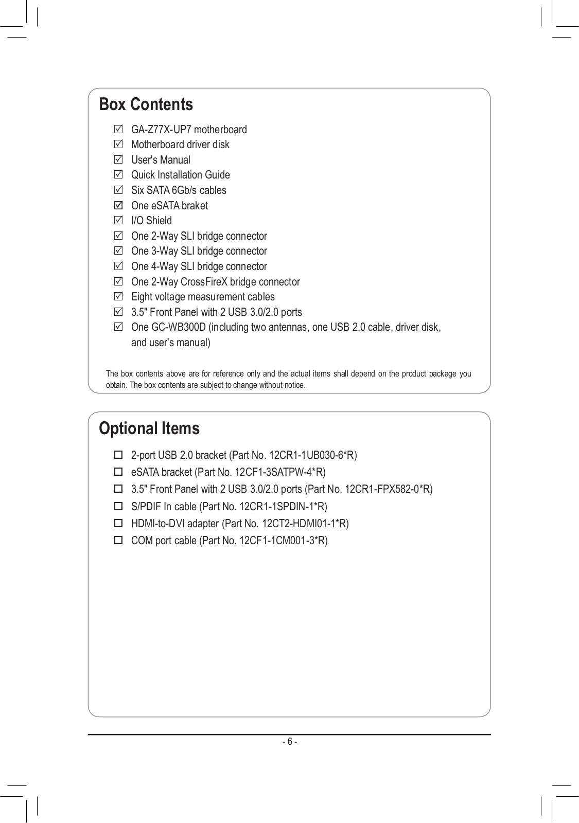
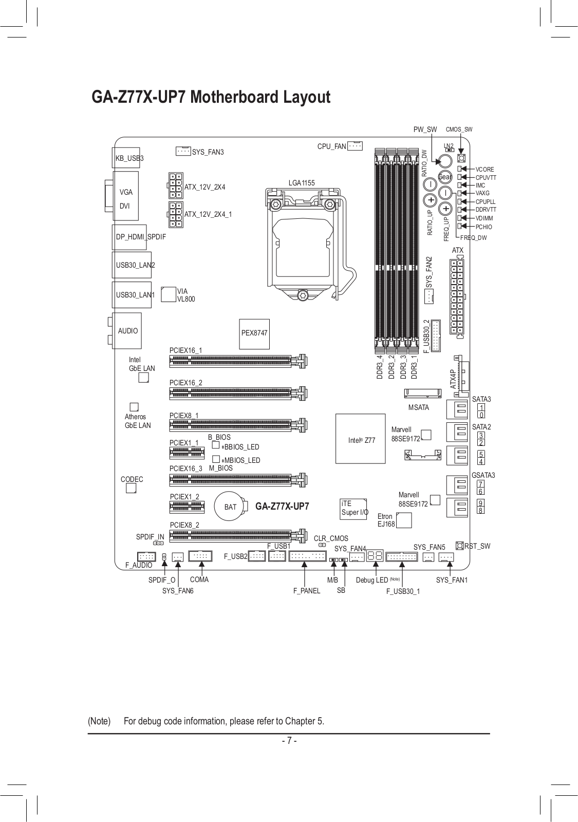
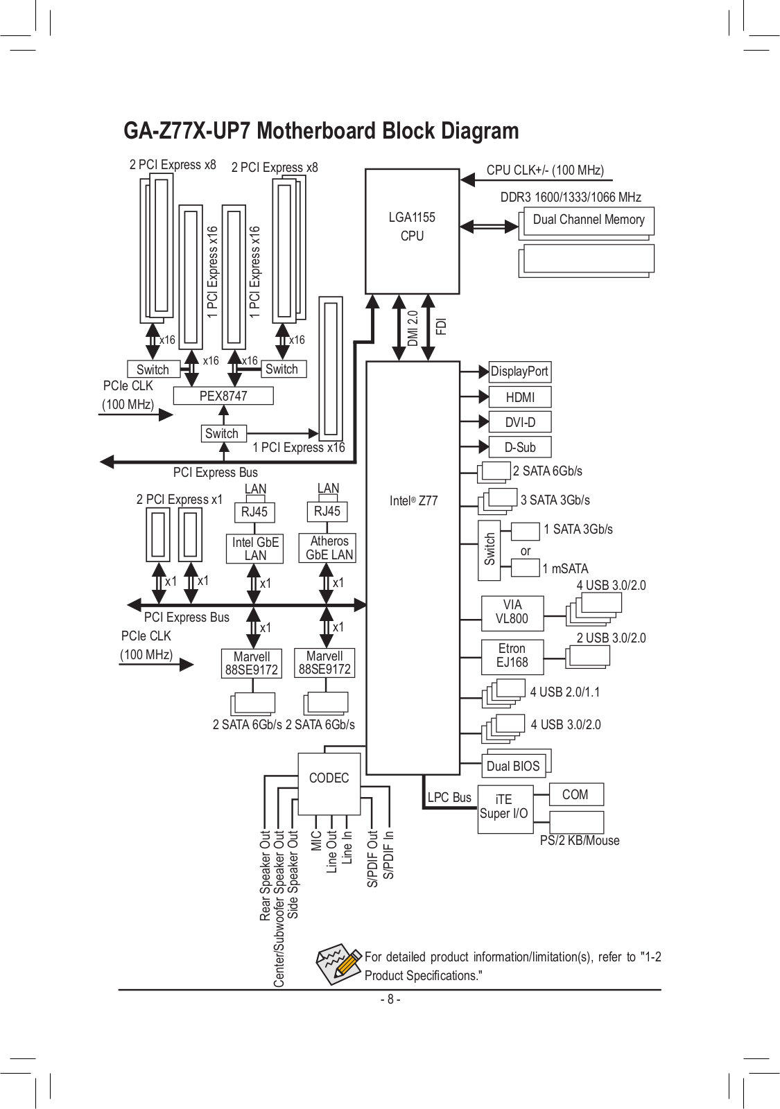
GA-Z77X-UP7
User Manual
128 pgs
40.57 Mb
0
User Manual [ko]
128 pgs
40.49 Mb
0
User Manual [ja]
128 pgs
40.81 Mb
0
Quick Start Manual
40 pgs
12.74 Mb
0
User Manual [zh]
128 pgs
42.68 Mb
0
Owner's Manual
3 pgs
1.03 Mb
0
Table of contents
Loading...
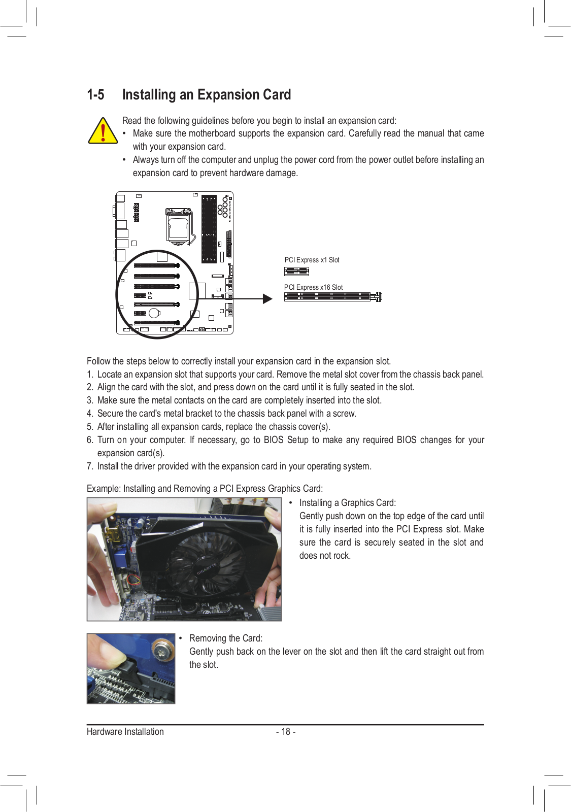
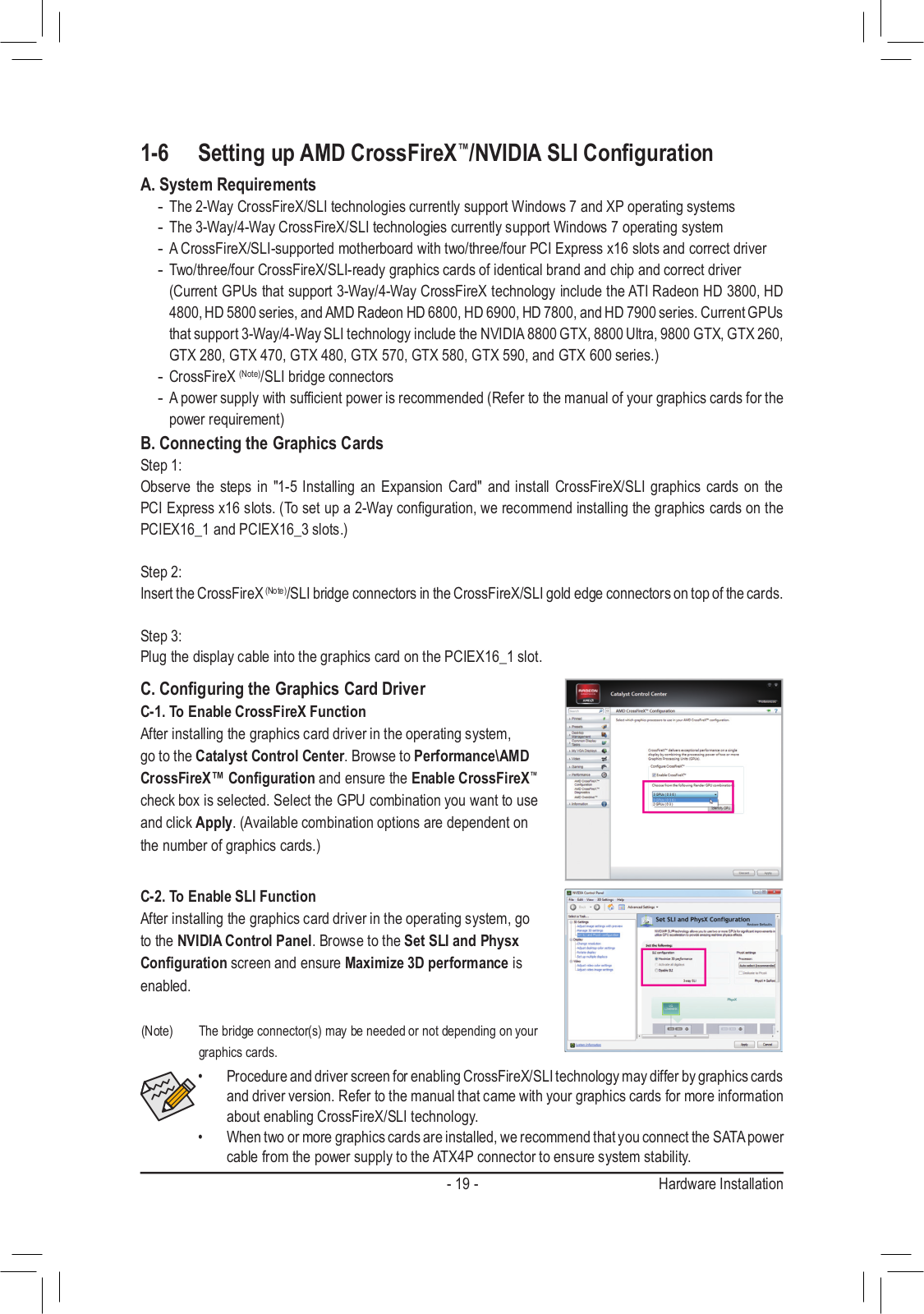
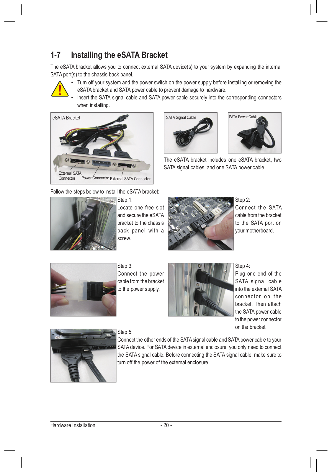
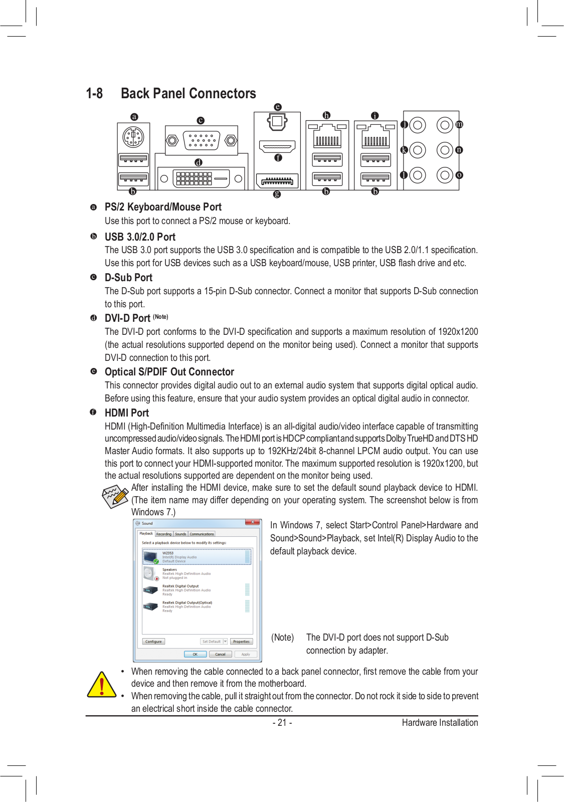
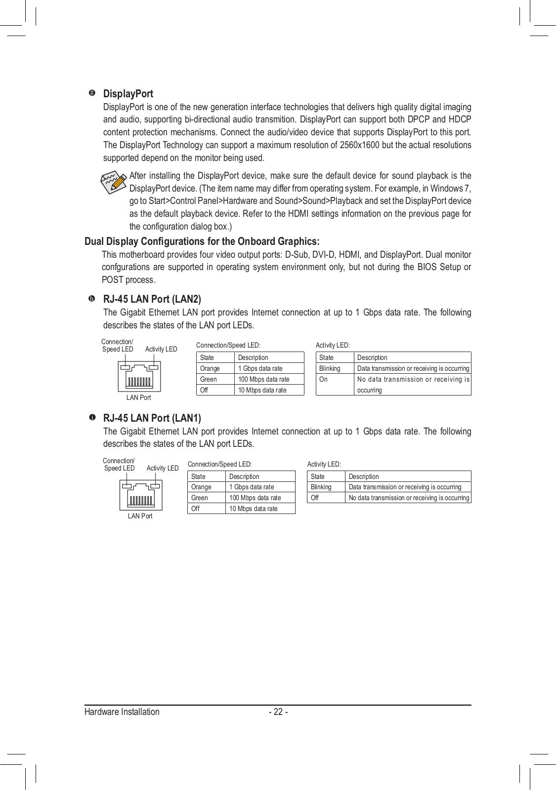
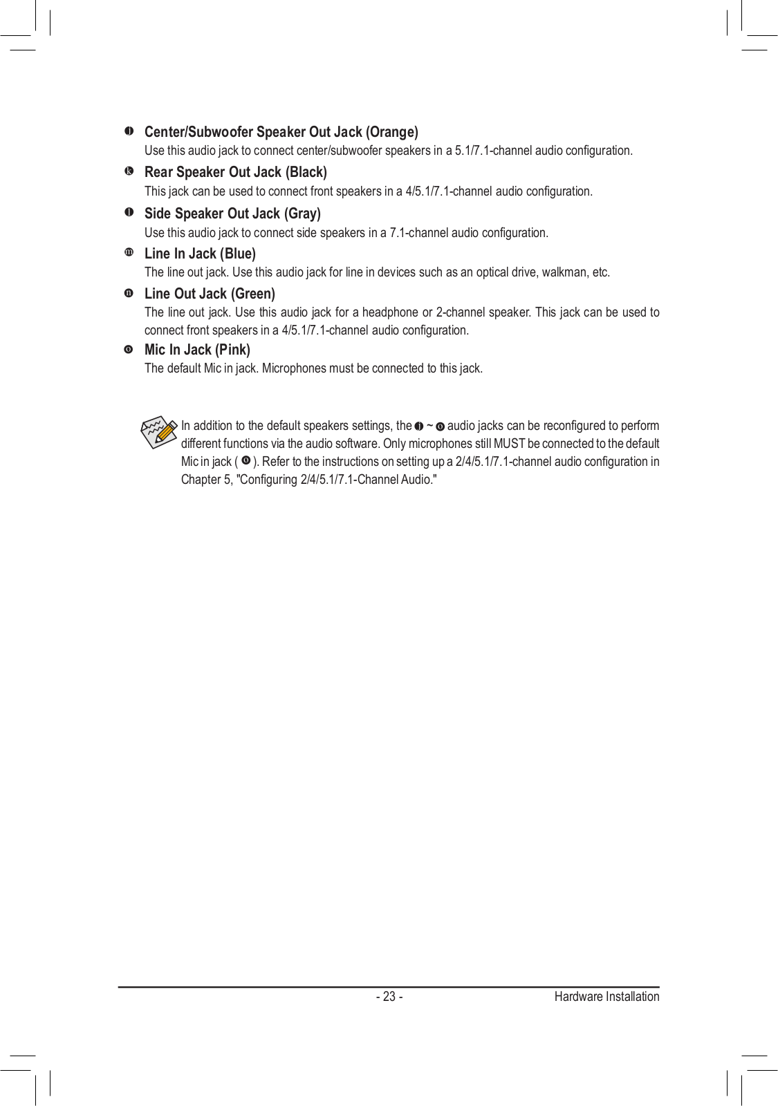
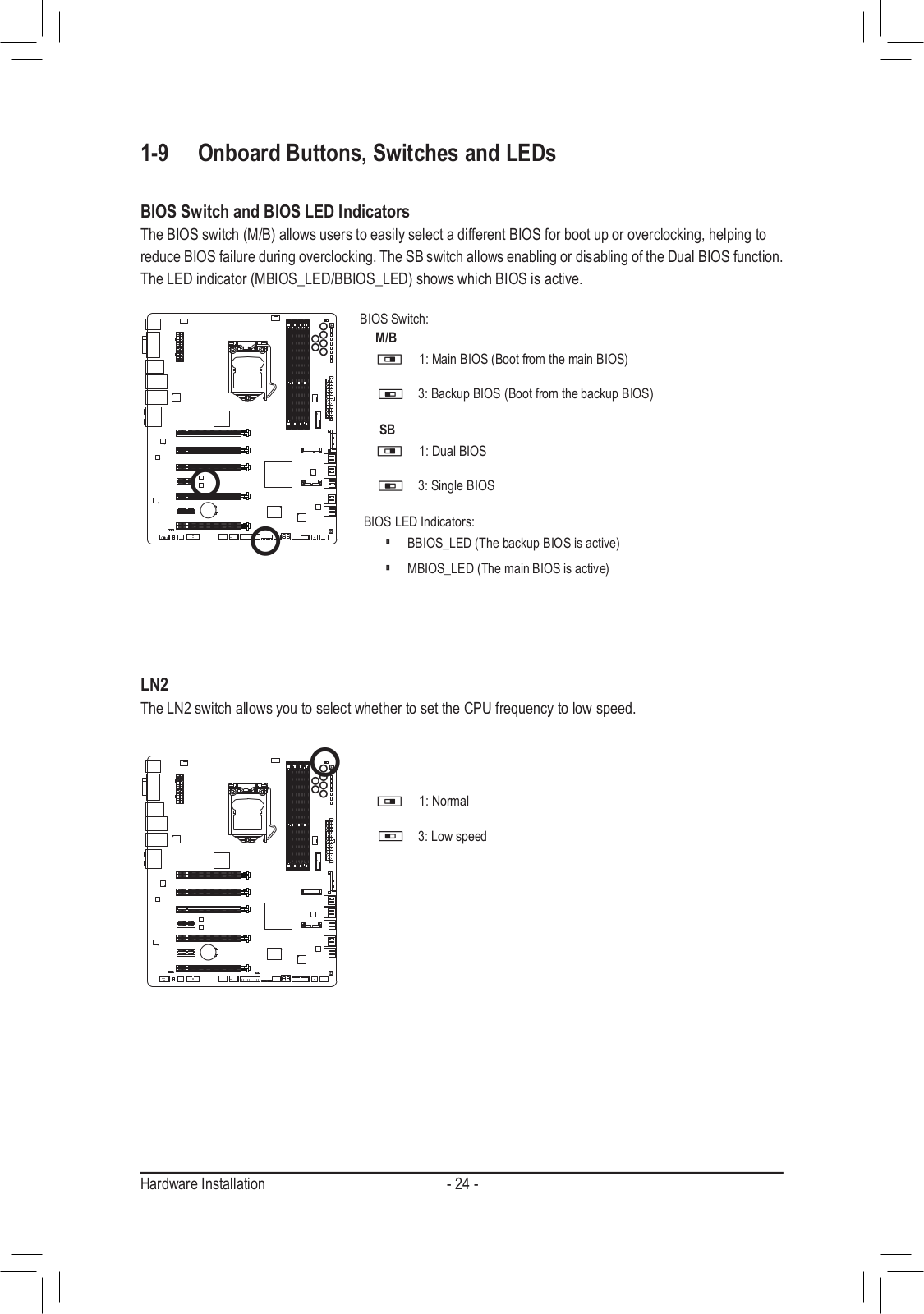
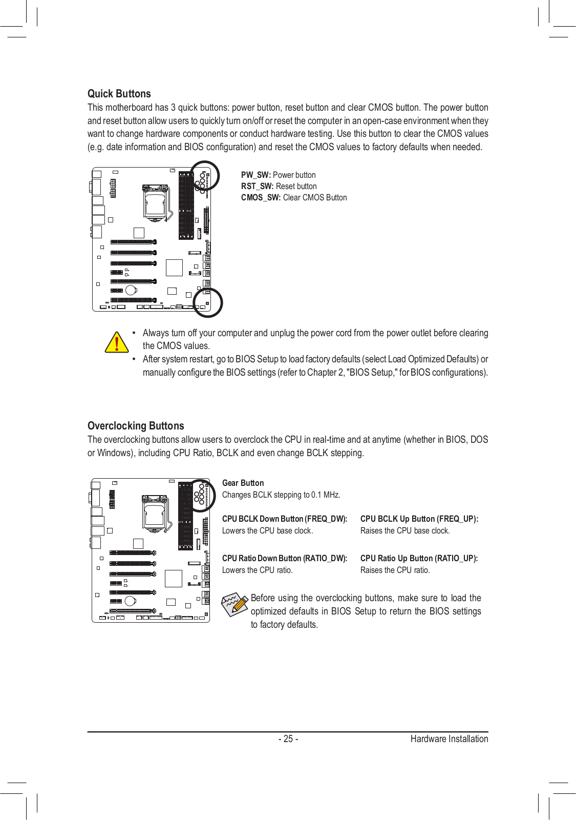
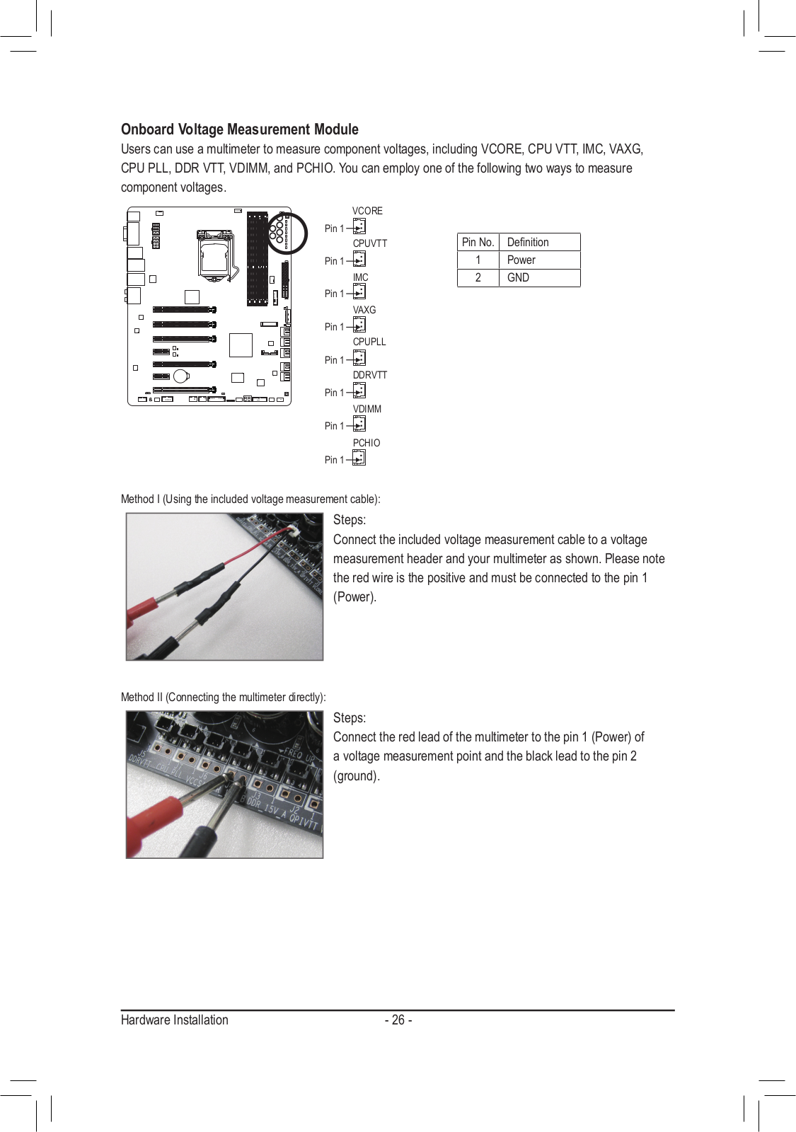
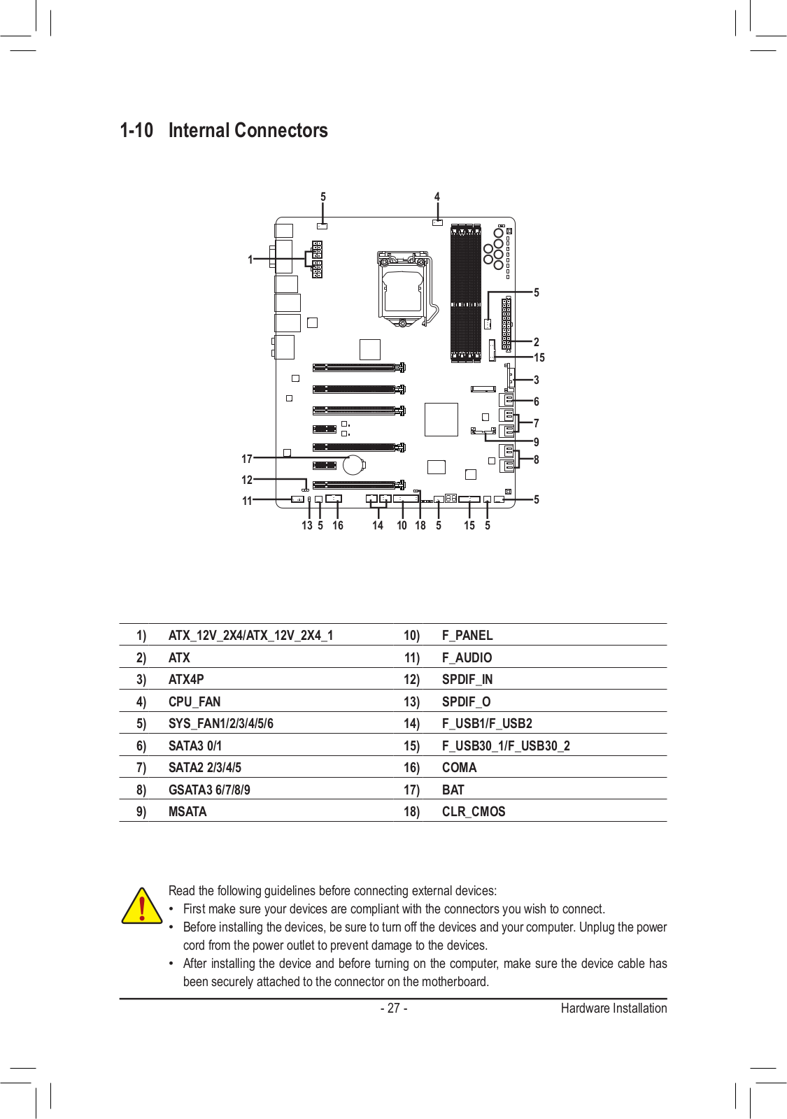
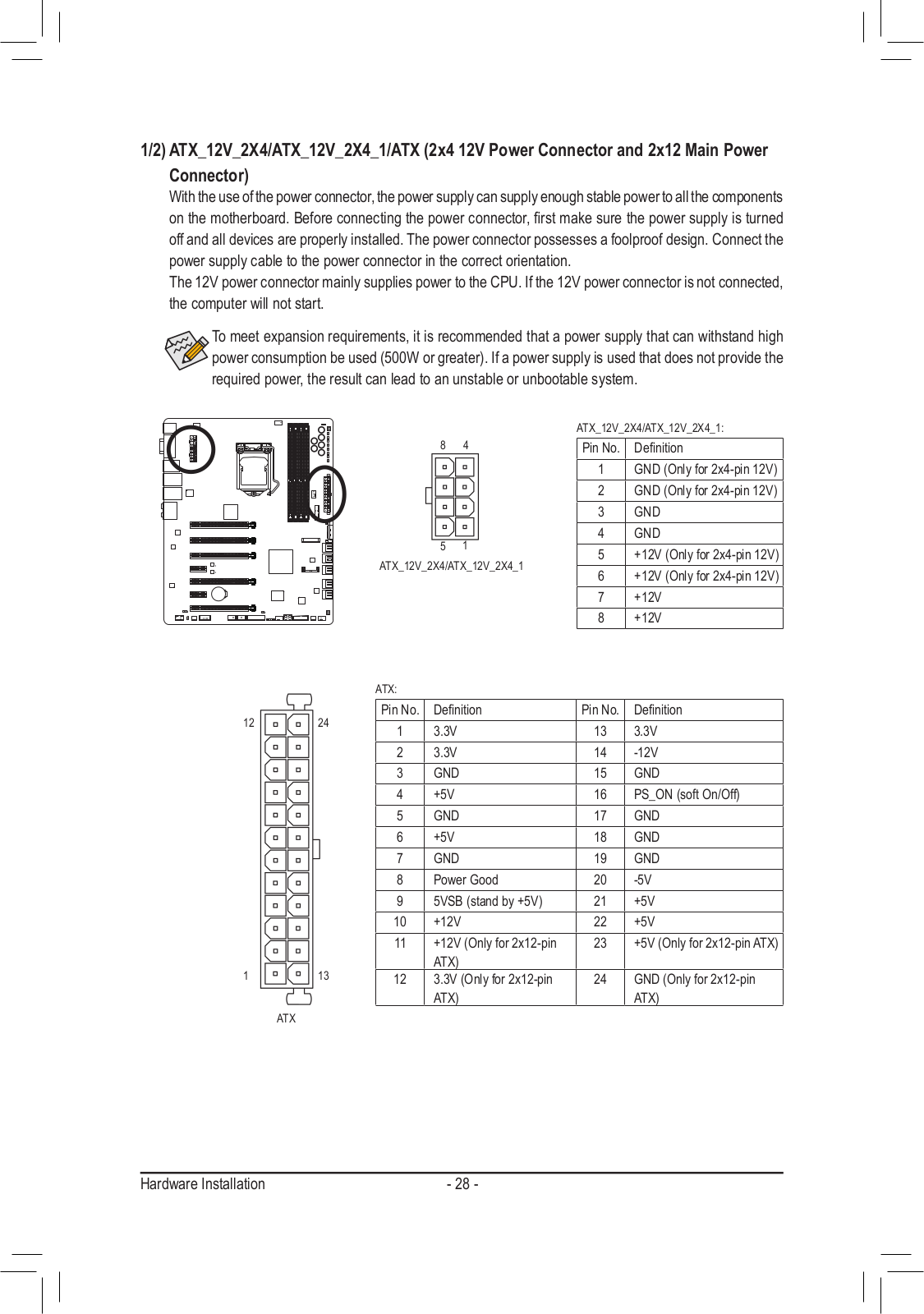
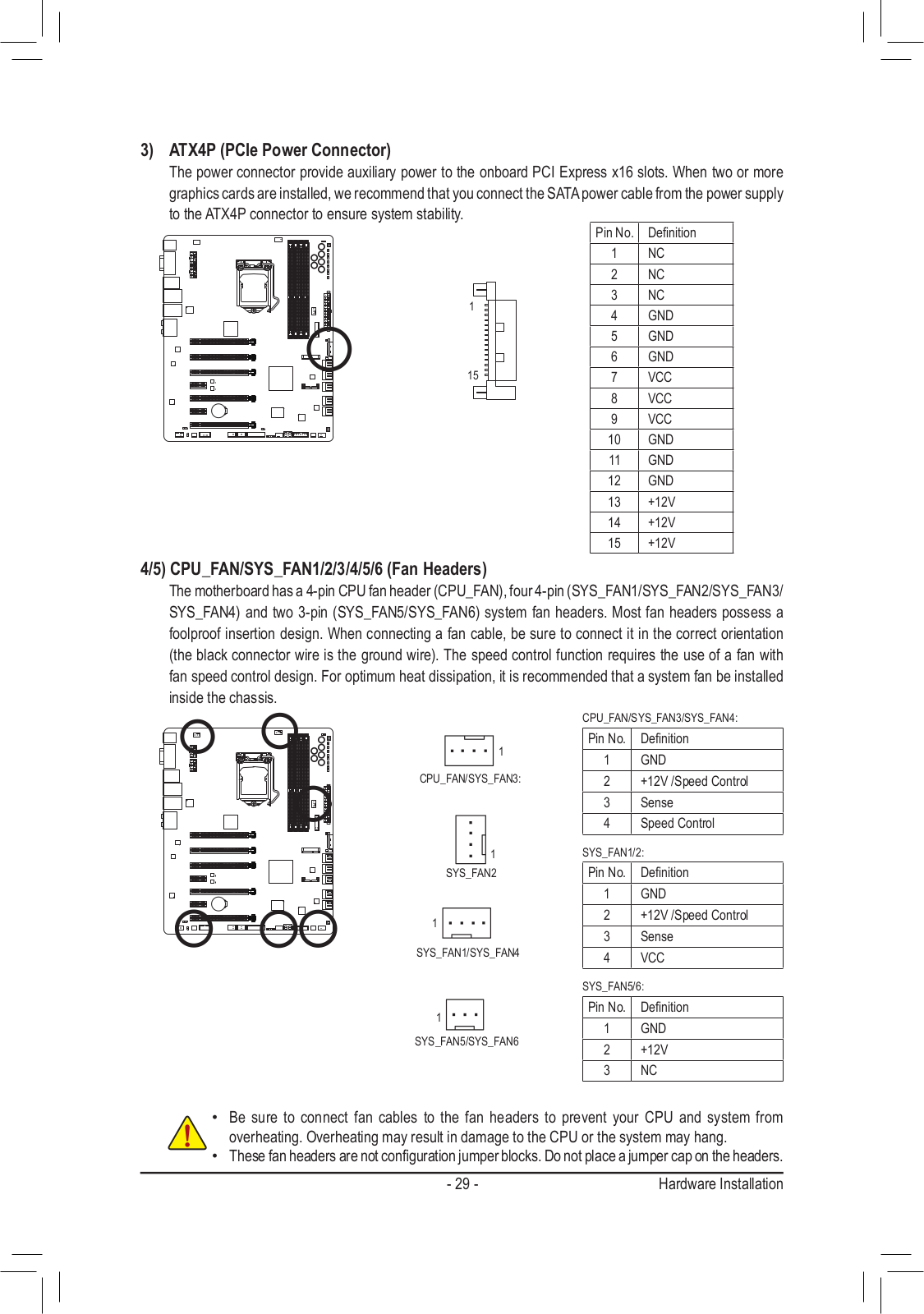
Gigabyte GA-Z77X-UP7 User Manual
...
Gigabyte User Manual
Download
Specifications and Main Features
Frequently Asked Questions
User Manual
Download
Loading...
+
98
hidden pages
Unhide
You need points to download manuals.
1 point = 1 manual.
You can buy points or you can get point for every manual you upload.
Buy points
Upload your manuals
 Loading...