

Gigabyte GA-Z77X-UP5 TH User Manual

GA-Z77X-UP5 TH
User's Manual
Rev. 1001
12ME-Z77XU5T-1001R
Jul. 6, 2012
Motherboard
GA-Z77X-UP5 TH
Jul. 6, 2012
Motherboard
GA-Z77X-UP5 TH
Copyright
© 2012 GIGA-BYTE TECHNOLOGY CO., LTD. All rights reserved.
The trademarks mentioned in this manual are legally registered to their respective owners.
Disclaimer
Information in this manual is protected by copyright laws and is the property of GIGABYTE.
Changes to the specications and features in this manual may be made by GIGABYTE
without prior notice. No part of this manual may be reproduced, copied, translated, transmitted,
orpublished in any form or by any means without GIGABYTE's prior written permission.
Documentation Classications
In order to assist in the use of this product, GIGABYTE provides the following types of
documentations:
For quick set-up of the product, read the Quick Installation Guide included with the product.
For detailed product information, carefully read the User's Manual.
For product-related information, check on our website at: http://www.gigabyte.com
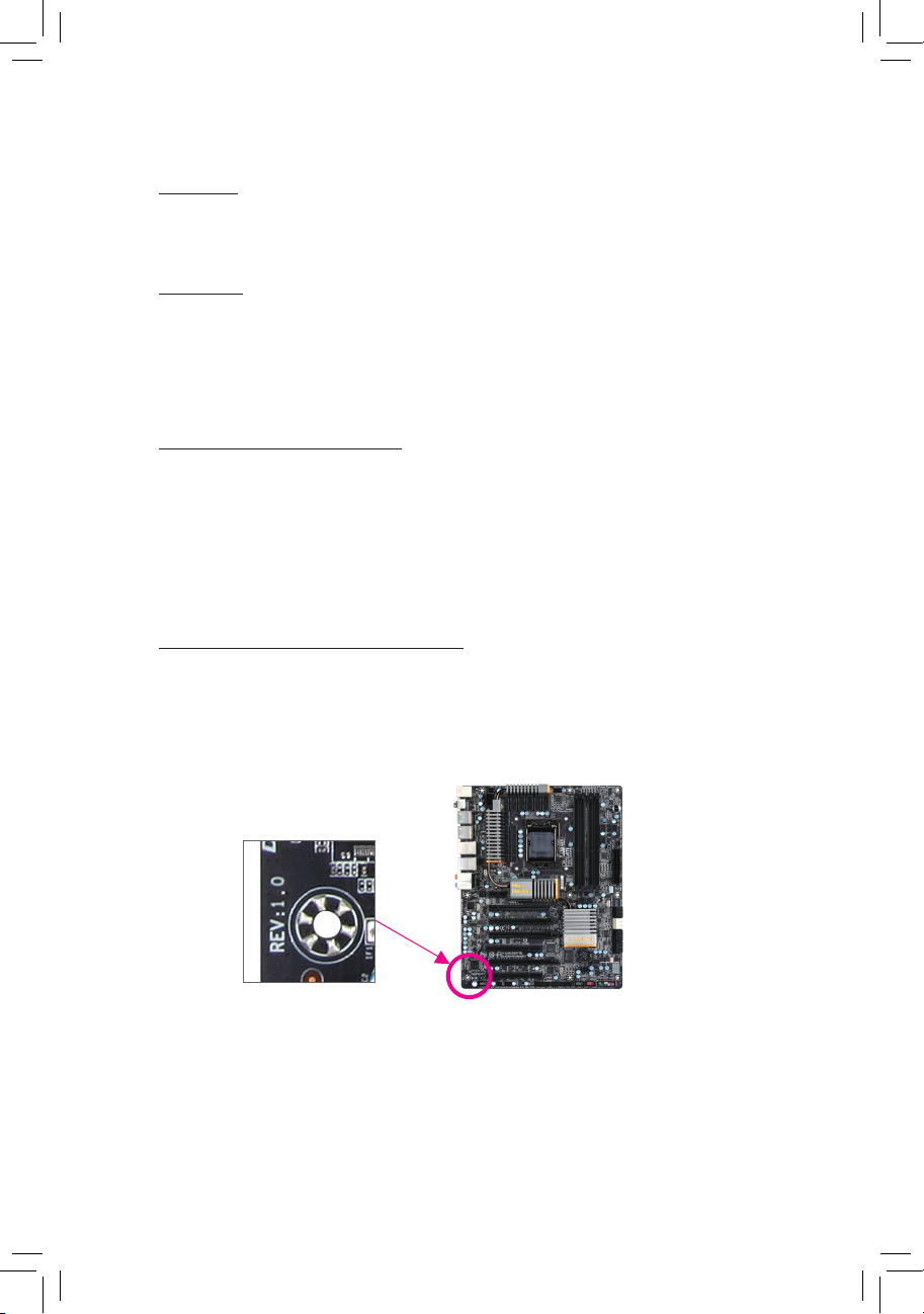
Identifying Your Motherboard Revision
The revision number on your motherboard looks like this: "REV: X.X." For example, "REV:
1.0" means the revision of the motherboard is 1.0. Check your motherboard revision before
updating motherboard BIOS, drivers, or when looking for technical information.
Example:

Table of Contents
Box Contents ...................................................................................................................6
Optional Items .................................................................................................................6
GA-Z77X-UP5 TH Motherboard Layout ..........................................................................7
GA-Z77X-UP5 TH Motherboard Block Diagram ..............................................................8
Chapter 1 Hardware Installation .....................................................................................9
1-1 Installation Precautions .................................................................................... 9
1-2 ProductSpecications .................................................................................... 10
1-3 Installing the CPU and CPU Cooler ............................................................... 14
1-3-1 Installing the CPU ...................................................................................................14
1-3-2 Installing the CPU Cooler .......................................................................................16
1-4 Installing the Memory ..................................................................................... 17
1-4-1 DualChannelMemoryConguration .....................................................................17
1-4-2 Installing a Memory ................................................................................................18
1-5 Installing an Expansion Card ......................................................................... 19
1-6 SettingupAMDCrossFireX™/NVIDIASLIConguration .............................. 20
1-7 Back Panel Connectors .................................................................................. 21
1-8 Onboard Buttons, Switches and LEDs ........................................................... 24
1-9 Internal Connectors ........................................................................................ 26
Chapter 2 BIOS Setup .................................................................................................. 37
2-1 Startup Screen ............................................................................................... 38
2-2 The Main Menu .............................................................................................. 39
2-3 M.I.T. .............................................................................................................. 41
2-4 System ........................................................................................................... 53
2-5 BIOS Features ............................................................................................... 54
2-6 Peripherals ..................................................................................................... 56
2-7 Power Management ....................................................................................... 61
2-8 Save & Exit ..................................................................................................... 63
Chapter 3 Drivers Installation ........................................................................................65
3-1 Installing Chipset Drivers ............................................................................... 65
3-2 Application Software ...................................................................................... 66
3-3 Technical Manuals .......................................................................................... 66
- 4 -

3-4 Contact ........................................................................................................... 67
3-5 System ........................................................................................................... 67
3-6 Download Center ........................................................................................... 68
3-7 New Program ................................................................................................. 68
Chapter 4 Unique Features ...........................................................................................69
4-1 Xpress Recovery2 .......................................................................................... 69
4-2 BIOS Update Utilities ..................................................................................... 72
4-2-1 Updating the BIOS with the Q-Flash Utility .............................................................72
4-2-2 Updating the BIOS with the @BIOS Utility .............................................................75
4-3 EasyTune 6 .................................................................................................... 76
4-4 Q-Share .......................................................................................................... 77
4-5 eXtreme Hard Drive (X.H.D) .......................................................................... 78
4-6 Auto Green ..................................................................................................... 79
4-7 EZ Setup ........................................................................................................ 80
4-7-1 Installing EZ Smart Response ................................................................................81
4-7-2 Installing EZ Rapid Start .........................................................................................82
4-7-3 Installing EZ Smart Connect ...................................................................................83
Chapter 5 Appendix ...................................................................................................... 85
5-1 ConguringSATAHardDrive(s) ..................................................................... 85
5-1-1 ConguringIntelZ77SATAControllers ..................................................................85
5-1-2 ConguringMarvell88SE9172SATAController .....................................................93
5-1-3 Installing the SATA RAID/AHCI Driver and Operating System ...............................99
5-2 ConguringAudioInputandOutput ............................................................. 108
5-2-1 Conguring2/4/5.1/7.1-ChannelAudio .................................................................108
5-2-2 ConguringS/PDIFIn/Out .................................................................................... 110
5-2-3 ConguringMicrophoneRecording ...................................................................... 112
5-2-4 Using the Sound Recorder ...................................................................................11 4
5-2-5 Creative Software Suite ........................................................................................11 5
5-3 Troubleshooting............................................................................................ 117
5-3-1 Frequently Asked Questions ................................................................................11 7
5-3-2 Troubleshooting Procedure ..................................................................................118
5-4 Debug LED Codes ....................................................................................... 120
5-5 Regulatory Statements ................................................................................. 124
- 5 -
Box Contents
5 GA-Z77X-UP5 TH motherboard
5 Motherboard driver disk
5 User's Manual
5 Quick Installation Guide
5 Six SATA 6Gb/s cables
5 I/O Shield
5 One 2-Way SLI bridge connector
5 3.5" Front Panel with 2 USB 3.0/2.0 ports
5 One GC-WB300D (including two antennas, one USB 2.0 cable, driver disk,
and user's manual)
The box contents above are for reference only and the actual items shall depend on the product package you obtain.
The box contents are subject to change without notice.
Optional Items
2-port USB 2.0 bracket (Part No. 12CR1-1UB030-6*R)
eSATA bracket (Part No. 12CF1-3SATPW-4*R)
2-port IEEE 1394a bracket (Part No. 12CF1-1IE008-0*R)
S/PDIF In cable (Part No. 12CR1-1SPDIN-1*R)
HDMI-to-DVI adapter (Part No. 12CT2-HDMI01-1*R)
- 6 -
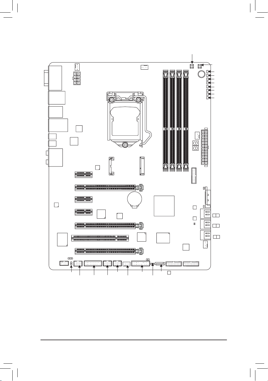
GA-Z77X-UP5 TH Motherboard Layout
CMOS_SW
DVI VGA
HDMI
R_USB30
USB_ESATA
USB30_LAN
MDP2
MDP1
AUDIO
CODEC
VIA
VT6308
F_AUDIO
SYS_FAN3
VIA
VL810
Intel
DSL3510L
PCIEX1_1
PCIEX16
PCIEX1_2
PCIEX1_3
PCIEX8
GA-Z77X-UP5 TH
PCI
PCIEX4
SPDIF_IN
ATX_12V_2X4
Intel
GbE LAN
PLX
PEX8605
LGA1155
mS ATA
Marvell
88SE9172
CPU_FAN
BAT
PCIe to PCI
Bridge
CLR_CMOS
Intel® Z77
iTE
Super I/O
DDR3_4
DDR3_3
DDR3_2
MBIOS_LED
BBIOS_LED
VIA
VL810
F_USB30_2F_USB30_3
(Note)
Debug LED
DDR3_1
M_BIOS
B_BIOS
PW_SW
ATX
SYS_FAN2
F_USB30_1
ATX4P
SYS_FAN1
RST_SW
VCORE
CPUVTT
IMC
VAXG
CPUPLL
DDRVTT
VDIMM
PCHIO
SATA 3
1 0
SATA 2
3 2
SATA 2
5 4
SPDIF_O
F_1394
TPM
F_USB2
F_USB1
SYS_FAN4
F_PANEL
(Note) For debug code information, please refer to Chapter 5.
- 7 -
SW4
GSATA3
8
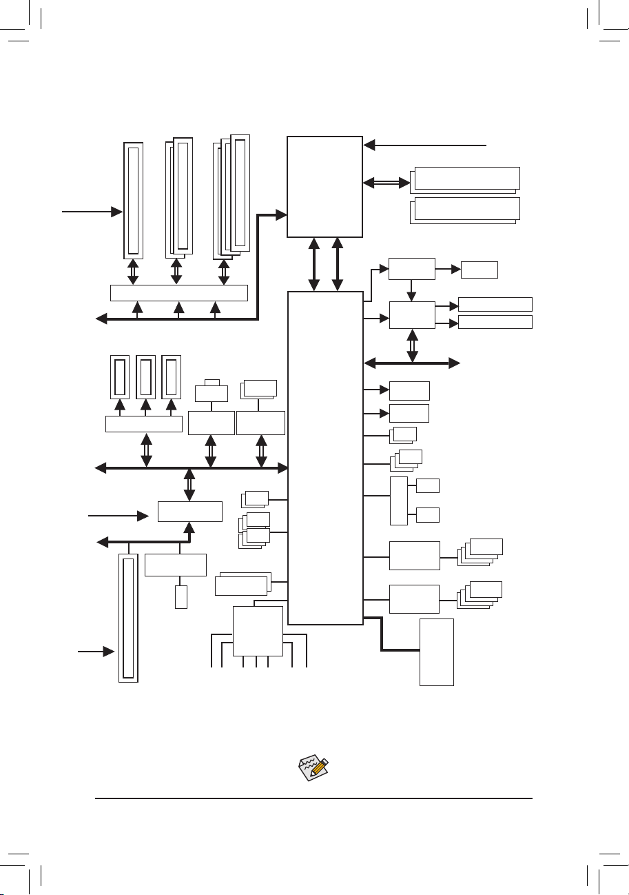
GA-Z77X-UP5 TH Motherboard Block Diagram
PCIe CLK
(100 MHz)
2 PCI Express x8
1 PCI Express x16
or
2 PCI Express x4+1 PCI Express x8
LGA1155
or
CPU
CPU CLK+/- (100 MHz)
DDR3 1600/1333/1066 MHz
Dual Channel Memory
PCIe CLK
(100 MHz)
PCI CLK
(33 MHz)
x16
Switch
PCI Express Bus
3 PCI Express x1
PLX PEX8605
x1
PCI Express Bus
PCIe to PCI Bridge
PCI Bus
VIA VT6308
1 IEEE 1394a
1 PCI
x16
x1
LAN
RJ45
Intel GbE
LAN
x1
2 USB 3.0/2.0
6 USB 2.0/1.1
Dual BIOS
x16
2 SATA 6Gb/s
Marvell
88SE9172
x1
CODEC
MIC
Line Out
Line In
DMI 2.0
Intel® Z77
S/PDIF In
S/PDIF Out
FDI
PCI Express Bus
Switch
Intel
DSL3510L
HDMI
D-Sub
Switch
VIA VL810
Hub
VIA VL810
Hub
LPC Bus
Thunderbolt (MDP2)
Thunderbolt (MDP1)
x4
2 SATA 6Gb/s
3 SATA 3Gb/s
1 SATA 3Gb/s
or
1 mSATA
4 USB 3.0/2.0
4 USB 3.0/2.0
iTE
Super
I/O
DVI-D
or
Surround Speaker Out
Center/Subwoofer Speaker Out
- 8 -
For detailed product information/limitation(s), refer
to"1-2ProductSpecications."

- 9 - Hardware Installation
Chapter 1 Hardware Installation
1-1 Installation Precautions
The motherboard contains numerous delicate electronic circuits and components which can become
damaged as a result of electrostatic discharge (ESD). Prior to installation, carefully read the user's
manual and follow these procedures:
• Prior to installation, make sure the chassis is suitable for the motherboard.
• Prior to installation, do not remove or break motherboard S/N (Serial Number) sticker or
warranty sticker provided by your dealer. These stickers are required for warranty validation.
• Always remove the AC power by unplugging the power cord from the power outlet before
installing or removing the motherboard or other hardware components.
• When connecting hardware components to the internal connectors on the motherboard, make
sure they are connected tightly and securely.
• When handling the motherboard, avoid touching any metal leads or connectors.
• It is best to wear an electrostatic discharge (ESD) wrist strap when handling electronic
components such as a motherboard, CPU or memory. If you do not have an ESD wrist strap,
keep your hands dry and rst touch a metal object to eliminate static electricity.
• Prior to installing the motherboard, please have it on top of an antistatic pad or within an
electrostatic shielding container.
• Before unplugging the power supply cable from the motherboard, make sure the power supply
has been turned off.
• Before turning on the power, make sure the power supply voltage has been set according to
the local voltage standard.
• Before using the product, please verify that all cables and power connectors of your hardware
components are connected.
• To prevent damage to the motherboard, do not allow screws to come in contact with the
motherboard circuit or its components.
• Make sure there are no leftover screws or metal components placed on the motherboard or
within the computer casing.
• Do not place the computer system on an uneven surface.
• Do not place the computer system in a high-temperature environment.
• Turning on the computer power during the installation process can lead to damage to system
components as well as physical harm to the user.
• If you are uncertain about any installation steps or have a problem related to the use of the
product, please consult a certied computer technician.
Hardware Installation
1-2 ProductSpecications
CPU Support for Intel® Core™ i7 processors/Intel® Core™ i5 processors/
Intel® Core™ i3 processors/Intel® Pentium® processors/Intel® Celeron® processors
in the LGA1155 package
(Go to GIGABYTE's website for the latest CPU support list.)
L3 cache varies with CPU
Chipset Intel® Z77 Express Chipset
Memory 4 x 1.5V DDR3 DIMM sockets supporting up to 32 GB of system memory
Onboard
Graphics
Audio Realtek ALC898 codec
LAN 1 x Intel GbE LAN chip (10/100/1000 Mbit)
Expansion Slots 1 x PCI Express x16 slot, running at x16 (PCIEX16)
* Due to Windows 32-bit operating system limitation, when more than 4 GB of physical
memory is installed, the actual memory size displayed will be less than 4 GB.
Dual channel memory architecture
Support for DDR3 1600/1333/1066 MHz memory modules
Support for non-ECC memory modules
Support for Extreme Memory Prole (XMP) memory modules
(Go to GIGABYTE's website for the latest supported memory speeds and memory
modules.)
Integrated Graphics Processor:
- 1 x D-Sub port
- 1 x DVI-D port, supporting a maximum resolution of 1920x1200
* The DVI-D port does not support D-Sub connection by adapter.
* Simultaneous output for DVI-D and the MDP2 Thunderbolt port is not supported.
- 1 x HDMI port, supporting a maximum resolution of 1920x1200
Intel DSL3510L chip:
- 2 Thunderbolt ports (MDP1/MDP2) support for Mini-DisplayPort and
Thunderbolt monitor(s), and supporting a maximum resolution of 2560x1600.
* When a monitor connected to the DVI-D port, the MDP2 Thunderbolt port can support
Thunderbolt storage device(s) only.
* Due to PC architecture I/O resources limitation, the amount of the Thunderbolt devices
can be used is dependent on the quantity of PCI Express and PCI devices be installed.
(Refer to Chapter 1-7, "Back Panel Connectors", and Chapter 2, "Peripherals\Intel(R)
Thunderbolt" for more information.)
Support for X-Fi Xtreme Fidelity® and EAX® Advanced HD™ 5.0 technologies
High Denition Audio
2/4/5.1/7.1-channel
Support for S/PDIF In/Out
* For optimum performance, if only one PCI Express graphics card is to be installed,
be sure to install it in the PCIEX16 slot.
1 x PCI Express x16 slot, running at x8 (PCIEX8)
* The PCIEX8 slot shares bandwidth with the PCIEX16 slot. When the PCIEX8 slot
is populated, the PCIEX16 slot will operate at up to x8 mode.
1 x PCI Express x16 slot, running at x4 (PCIEX4)
* The PCIEX4 slot is available only when an Intel 22nm (Ivy Bridge) CPU is installed.
* The PCIEX4 slot shares bandwidth with the PCIEX8 and PCIEX16 slots. When the
PCIEX4 slot is populated, the PCIEX16 slot will operate at up to x8 mode and the
PCIEX8 will operate at up to x4 mode.
- 10 -
- 9 - Hardware Installation
Expansion Slots (The PCIEX16, PCIEX8, and PCIEX4 slots conform to PCI Express 3.0 standard.)
* Whether PCI Express 3.0 is supported depends on CPU and graphics card
compatibility.
3 x PCI Express x1 slots
(All PCI Express x1 slots conform to PCI Express 2.0 standard.)
1 x PCI slot
Multi-Graphics
Technology
Support for AMD CrossFireX™ / NVIDIA SLI technology
Storage Interface Chipset:
- 2 x SATA 6Gb/s connectors (SATA3 0/SATA3 1) supporting up to 2 SATA
6Gb/s devices
- 4 x SATA 3Gb/s connectors (SATA2 2~5) supporting up to 4 SATA 3Gb/s
devices
- 1 x mSATA connector
* The SATA2 5 connector will become unavailable when the mSATA connector is
installed with a solid state drive.
- Support for RAID 0, RAID 1, RAID 5, and RAID 10
* When a RAID set is built across the SATA 6Gb/s and SATA 3Gb/s channels, the
system performance of the RAID set may vary depending on the devices being
connected.
Marvell 88SE9172 chip:
- 1 x SATA 6Gb/s connector (GSATA3 8) supporting up to 1 SATA 6Gb/s device
- 1 x eSATA 6Gb/s connector on the back panel supporting up to 1 SATA 6Gb/s
device
- Support for RAID 0 and RAID 1
USB Chipset:
- Up to 2 USB 3.0/2.0 ports (available through the internal USB headers)
- Up to 6 USB 2.0/1.1 ports (2 ports on the back panel, 4 ports available through
the internal USB headers)
Chipset + 2 VIA VL810 Hubs:
- Up to 8 USB 3.0/2.0 ports (4 ports on the back panel, 4 ports available through
the internal USB headers)
* In Windows XP, the Intel USB 3.0 ports and VIA VL810 HUB can support up to USB 2.0
* Due to a Windows 7 limitation, please connect your USB device(s) to the USB 2.0/1.1
transfer speed.
port(s) before the Intel USB 3.0 controller driver is installed.
IEEE 1394 VIA VT6308 chip:
- Up to 2 IEEE 1394a ports (1 port on the back panel, 1 port available through
the internal IEEE 1394a header)
Thunderbolt Intel DSL3510L chip:
- 2 Thunderbolt ports on the back panel
Internal
Connectors
1 x 24-pin ATX main power connector
1 x 8-pin ATX 12V power connector
1 x PCIe power connector
3 x SATA 6Gb/s connectors
4 x SATA 3Gb/s connectors
1 x mSATA connector
Hardware Installation
Internal
Connectors
1 x CPU fan header
4 x system fan headers
1 x front panel header
1 x front panel audio header
1 x S/PDIF Out header
1 x S/PDIF In header
3 x USB 3.0/2.0 headers
2 x USB 2.0/1.1 headers
1 x IEEE 1394a port
1 x Clear CMOS jumper
1 x Trusted Platform Module (TPM) header
1 x power button
1 x reset button
1 x Clear CMOS button
1 x BIOS switch button
Voltage Measurement Points
Back Panel
Connectors
1 x D-Sub port
1 x DVI-D port
1 x optical S/PDIF Out connector
1 x HDMI port
2 x Thunderbolt ports
1 x eSATA 6Gb/s connector
4 x USB 3.0/2.0 ports
2 x USB 2.0/1.0 ports
1 x IEEE 1394a port
1 x RJ-45 port
5 x audio jacks (Center/Subwoofer Speaker Out, Rear Speaker Out, Line In,
Line Out, Mic In)
I/O Controller iTE I/O Controller Chip
Hardware
Monitor
System voltage detection
CPU/System temperature detection
CPU/System fan speed detection
CPU overheating warning
CPU/System fan fail warning
CPU/System fan speed control
* Whether the CPU/system fan speed control function is supported will depend on the
CPU/system cooler you install.
BIOS 2 x 64 Mbit ash
Use of licensed AMI EFI BIOS
Support for DualBIOS™
PnP 1.0a, DMI 2.0, SM BIOS 2.6, ACPI 2.0a
- 12 -
- 9 - Hardware Installation
Unique Features Support for @BIOS
Support for Q-Flash
Support for Xpress Install
Support for Xpress Recovery2
Support for EasyTune
* Available functions in EasyTune may differ by motherboard model.
Support for eXtreme Hard Drive (X.H.D)
Support for Auto Green
Support for ON/OFF Charge
Support for Q-Share
Support for 3D Power
Support for EZ Setup
Bundled
Software
Norton Internet Security (OEM version)
Intel® Rapid Start Technology
Intel® Smart Connect Technology
Intel® Smart Response Technology
LucidLogix Virtu MVP
* Make sure the monitor cable has been connected to the integrated graphics port on
the back panel.
Operating
System
Support for Microsoft® Windows 7/XP
Form Factor ATX Form Factor; 30.5cm x 24.4cm
* GIGABYTE reserves the right to make any changes to the product specifications and product-related information without
prior notice.
* Please visit GIGABYTE's website to check the supported operating system(s) for the software listed in the "Unique
Features" and "Bundled Software" columns.
Hardware Installation
1-3 Installing the CPU and CPU Cooler
Read the following guidelines before you begin to install the CPU:
• Make sure that the motherboard supports the CPU.
(Go to GIGABYTE's website for the latest CPU support list.)
• Always turn off the computer and unplug the power cord from the power outlet before installing the
CPU to prevent hardware damage.
• Locate the pin one of the CPU. The CPU cannot be inserted if oriented incorrectly. (Or you may
locate the notches on both sides of the CPU and alignment keys on the CPU socket.)
• Apply an even and thin layer of thermal grease on the surface of the CPU.
• Do not turn on the computer if the CPU cooler is not installed, otherwise overheating and damage
of the CPU may occur.
• Set the CPU host frequency in accordance with the CPU specications. It is not recommended
that the system bus frequency be set beyond hardware specications since it does not meet the
standard requirements for the peripherals. If you wish to set the frequency beyond the standard
specications, please do so according to your hardware specications including the CPU, graphics
card, memory, hard drive, etc.
1-3-1 Installing the CPU
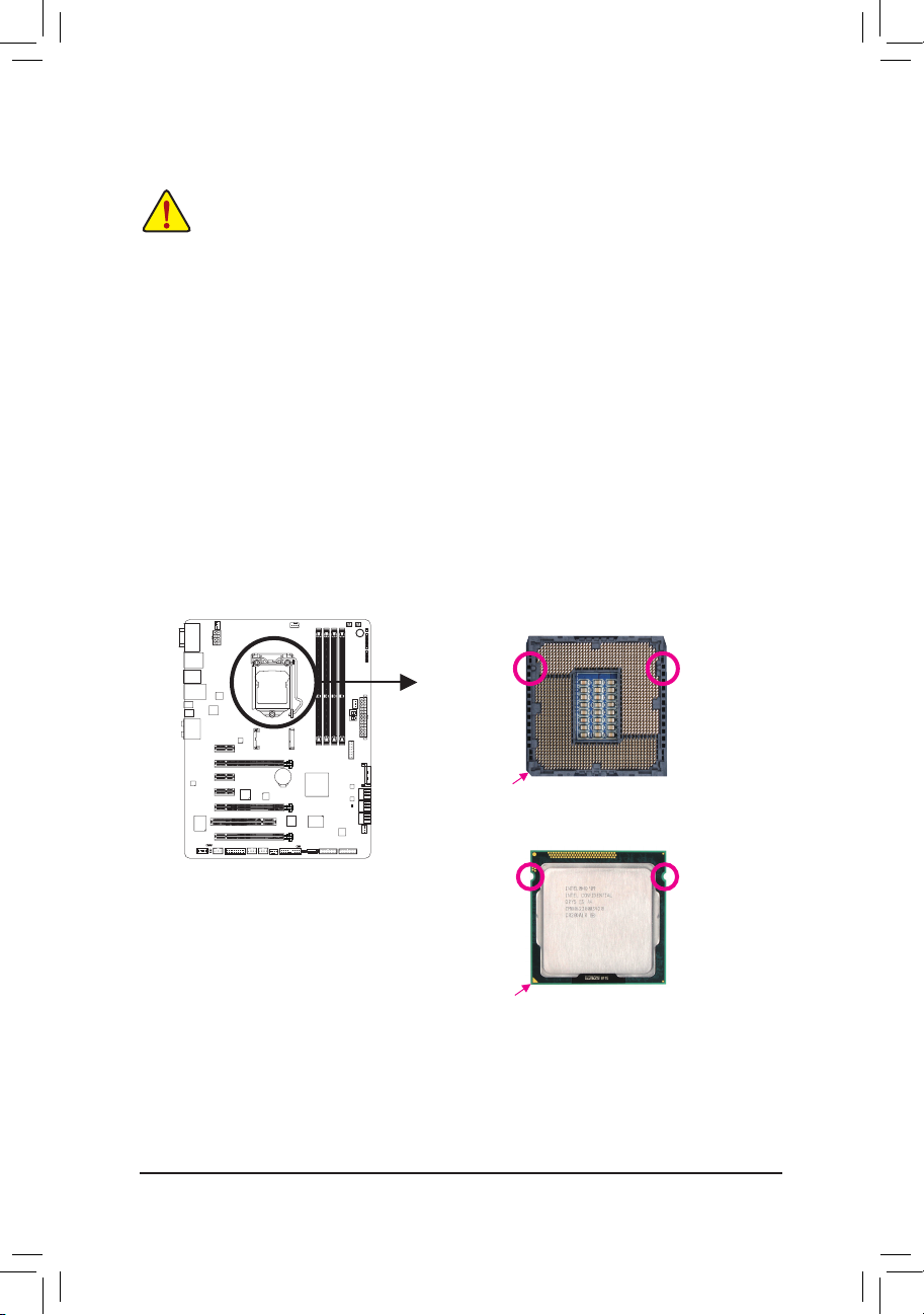
A. Locate the alignment keys on the motherboard CPU socket and the notches on the CPU.
LGA1155 CPU Socket
Alignment KeyAlignment Key
Pin One Corner of the CPU Socket
LGA1155 CPU
Notch
Triangle Pin One Marking on the CPU
- 14 -
Notch
- 9 - Hardware Installation
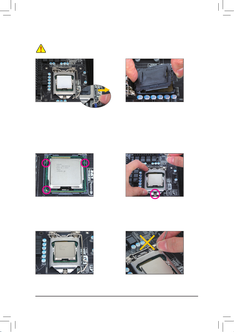
B. Follow the steps below to correctly install the CPU into the motherboard CPU socket.
Before installing the CPU, make sure to turn off the computer and unplug the power cord from
the power outlet to prevent damage to the CPU.
Step 1:
Gently press the CPU socket lever handle down
and away from the socket with your nger. Then
completely lift the CPU socket lever and the metal
load plate will be lifted as well.
Step 3:
Hold the CPU with your thumb and index ngers.
Align the CPU pin one marking (triangle) with the
pin one corner of the CPU socket (or you may align
the CPU notches with the socket alignment keys)
and gently insert the CPU into position.
Step 2:
Remove the CPU socket cover as shown. Hold
your index nger down on the rear grip of the
socket cover and use your thumb to lift up the
front edge (next to the "REMOVE" mark) and
then remove the cover. (DO NOT touch socket
contacts. To protect the CPU socket, always
replace the protective socket cover when the CPU
is not installed.)
Step 4:
Once the CPU is properly inserted, use one hand
to hold the socket lever and use the other to lightly
replace the load plate. When replacing the load
plate, make sure the front end of the load plate is
under the shoulder screw.
Step 5:
Push the CPU socket lever back into its locked
position.
NOTE:
Hold the CPU socket lever by the handle, not the
lever base portion.
Hardware Installation
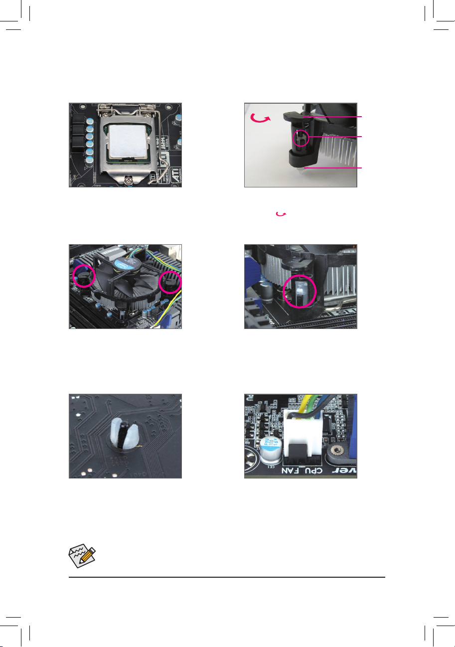
1-3-2 Installing the CPU Cooler
Follow the steps below to correctly install the CPU cooler on the motherboard. (The following procedure uses
Intel® boxed cooler as the example cooler.)
Male
Direction of
the Arrow Sign
on the Male
Push Pin
Push Pin
The Top
of Female
Push Pin
Female
Push Pin
Step 1:
Apply an even and thin layer of thermal grease on
the surface of the installed CPU.
Step 3:
Place the cooler atop the CPU, aligning the
four push pins through the pin holes on the
motherboard. Push down on the push pins
diagonally.
Step 2:
Before installing the cooler, note the direction of the
arrow sign on the male push pin. (Turning the
push pin along the direction of arrow is to remove
the cooler, on the contrary, is to install.)
Step 4:
You should hear a "click" when pushing down each
push pin. Check that the Male and Female push
pins are joined closely.
(Refer to your CPU cooler installation manual for
instructions on installing the cooler.)
Step 5:
After the installation, check the back of the
motherboard. If the push pin is inserted as the
picture above shows, the installation is complete.
Use extreme care when removing the CPU cooler because the thermal grease/tape between the CPU
cooler and CPU may adhere to the CPU. Inadequately removing the CPU cooler may damage the CPU.
Step 6:
Finally, attach the power connector of the CPU
cooler to the CPU fan header (CPU_FAN) on the
motherboard.
- 16 -
- 9 - Hardware Installation
1-4 Installing the Memory
Read the following guidelines before you begin to install the memory:
• Make sure that the motherboard supports the memory. It is recommended that memory of the same
capacity, brand, speed, and chips be used.
(Go to GIGABYTE's website for the latest supported memory speeds and memory modules.)
• Always turn off the computer and unplug the power cord from the power outlet before installing the
memory to prevent hardware damage.
• Memory modules have a foolproof design. A memory module can be installed in only one direction.
If you are unable to insert the memory, switch the direction.
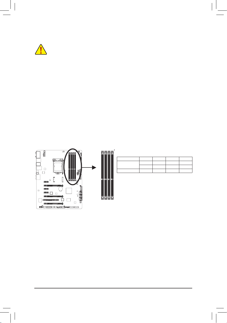
1-4-1 DualChannelMemoryConguration
This motherboard provides four DDR3 memory sockets and supports Dual Channel Technology. After the
memory is installed, the BIOS will automatically detect the specications and capacity of the memory. Enabling
Dual Channel memory mode will double the original memory bandwidth.
The four DDR3 memory sockets are divided into two channels and each channel has two memory sockets as
following:
Channel A: DDR3_2, DDR3_4
Channel B: DDR3_1, DDR3_3
Dual Channel Memory Congurations Table
Two Modules - - DS/SS - - DS/SS
Four Modules DS/SS DS/SS DS/SS DS/SS
(SS=Single-Sided, DS=Double-Sided, "- -"=No Memory)
DDR3_1
DDR3_2
DDR3_3
DDR3_4
DDR3_4 DDR3_2 DDR3_3 DDR3_1
DS/SS - - DS/SS - -
Due to CPU limitations, read the following guidelines before installing the memory in Dual Channel mode.
1. Dual Channel mode cannot be enabled if only one DDR3 memory module is installed.
2. When enabling Dual Channel mode with two or four memory modules, it is recommended that memory
of the same capacity, brand, speed, and chips be used. For optimum performance, when enabling
Dual Channel mode with two memory modules, we recommend that you install them in the DDR3_1
and DDR3_2 sockets.
Hardware Installation
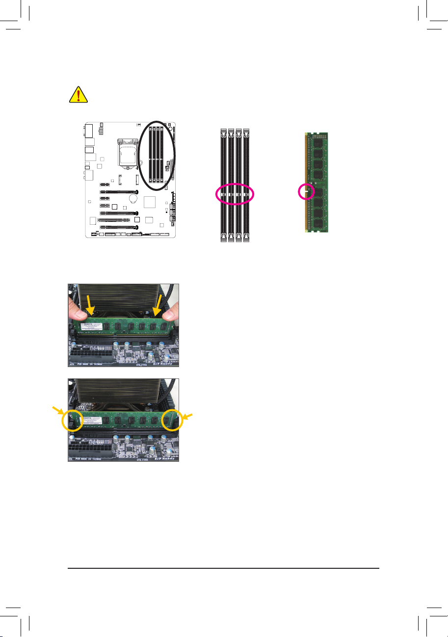
1-4-2 Installing a Memory
Before installing a memory module, make sure to turn off the computer and unplug the power
cord from the power outlet to prevent damage to the memory module. DDR3 and DDR2 DIMMs are
not compatible to each other or DDR DIMMs. Be sure to install DDR3 DIMMs on this motherboard.
Notch
DDR3 DIMM
A DDR3 memory module has a notch, so it can only t in one direction. Follow the steps below to correctly install
your memory modules in the memory sockets.
Step 1:
Note the orientation of the memory module. Spread the retaining clips
at both ends of the memory socket. Place the memory module on the
socket. As indicated in the picture on the left, place your ngers on
the top edge of the memory, push down on the memory and insert it
vertically into the memory socket.
Step 2:
The clips at both ends of the socket will snap into place when the
memory module is securely inserted.
- 18 -
- 9 - Hardware Installation
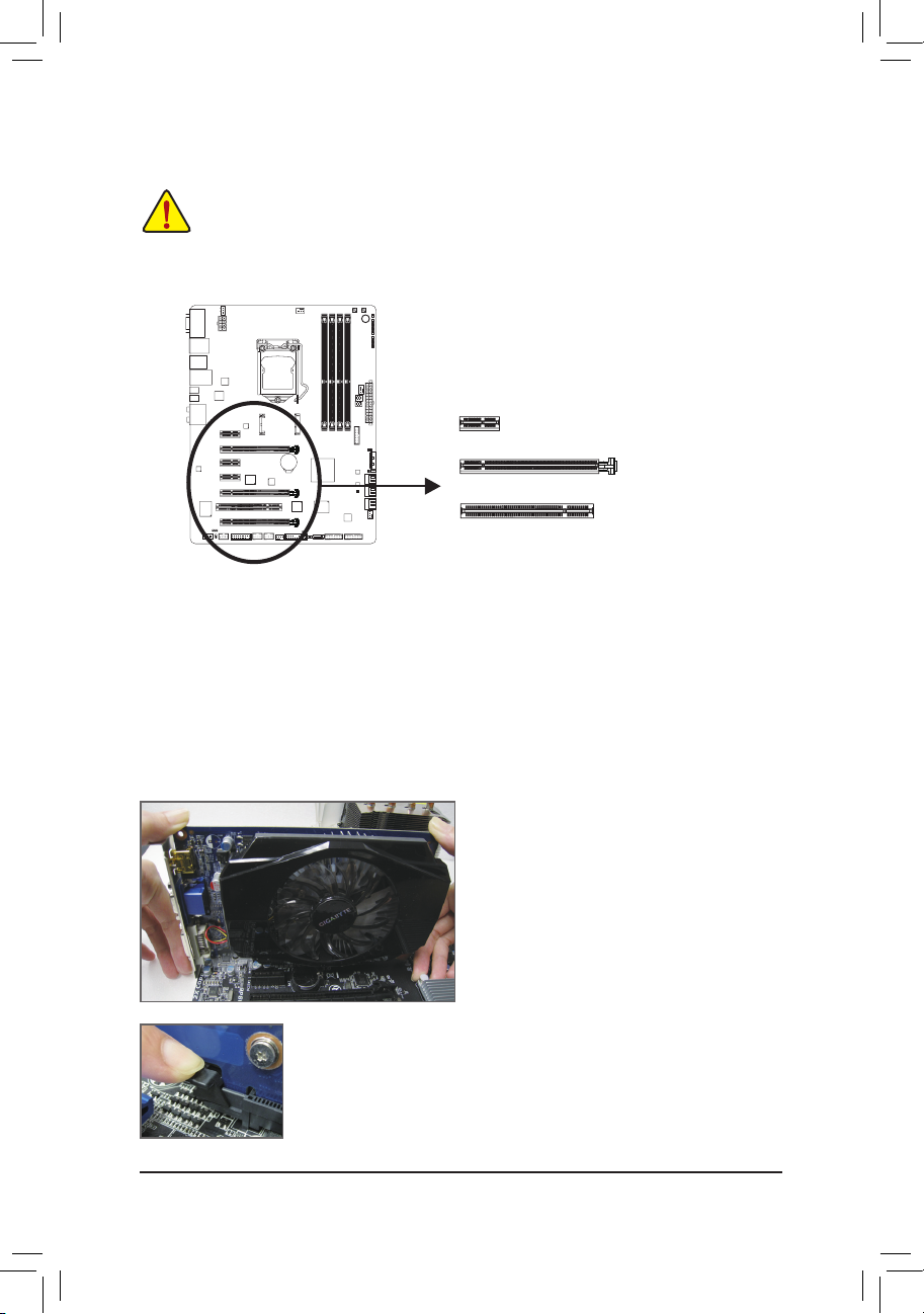
1-5 Installing an Expansion Card
Read the following guidelines before you begin to install an expansion card:
• Make sure the motherboard supports the expansion card. Carefully read the manual that came
with your expansion card.
• Always turn off the computer and unplug the power cord from the power outlet before installing an
expansion card to prevent hardware damage.
PCI Express x1 Slot
PCI Express x16 Slot
PCI Slot
Follow the steps below to correctly install your expansion card in the expansion slot.
1. Locate an expansion slot that supports your card. Remove the metal slot cover from the chassis back panel.
2. Align the card with the slot, and press down on the card until it is fully seated in the slot.
3. Make sure the metal contacts on the card are completely inserted into the slot.
4. Secure the card's metal bracket to the chassis back panel with a screw.
5. After installing all expansion cards, replace the chassis cover(s).
6. Turn on your computer. If necessary, go to BIOS Setup to make any required BIOS changes for your
expansion card(s).
7. Install the driver provided with the expansion card in your operating system.
Example: Installing and Removing a PCI Express Graphics Card:
• Installing a Graphics Card:
Gently push down on the top edge of the card until
it is fully inserted into the PCI Express slot. Make
sure the card is securely seated in the slot and
does not rock.
• Removing the Card:
Gently push back on the lever on the slot and then lift the card straight out from
the slot.
Hardware Installation
1-6 SettingupAMDCrossFireX™/NVIDIASLIConguration
A. System Requirements
- Windows 7 or Windows XP operating system
- A CrossFireX/SLI-supported motherboard with two PCI Express x16 slots and correct driver
- Two CrossFireX/SLI-ready graphics cards of identical brand and chip and correct driver
- CrossFireX
- A power supply with sufcient power is recommended (Refer to the manual of your graphics cards for the
power requirement)
B. Connecting the Graphics Cards
Step 1:
Observe the steps in "1-5 Installing an Expansion Card" and install CrossFireX/SLI graphics cards on the PCI
Express x16 slots.
(Note)
/SLI bridge connector
Step 2:
Insert the CrossFireX
Step 3:
Plug the display cable into the graphics card on the PCIEX16 slot.
(Note)
/SLI bridge connectors in the CrossFireX/SLI gold edge connectors on top of the cards.
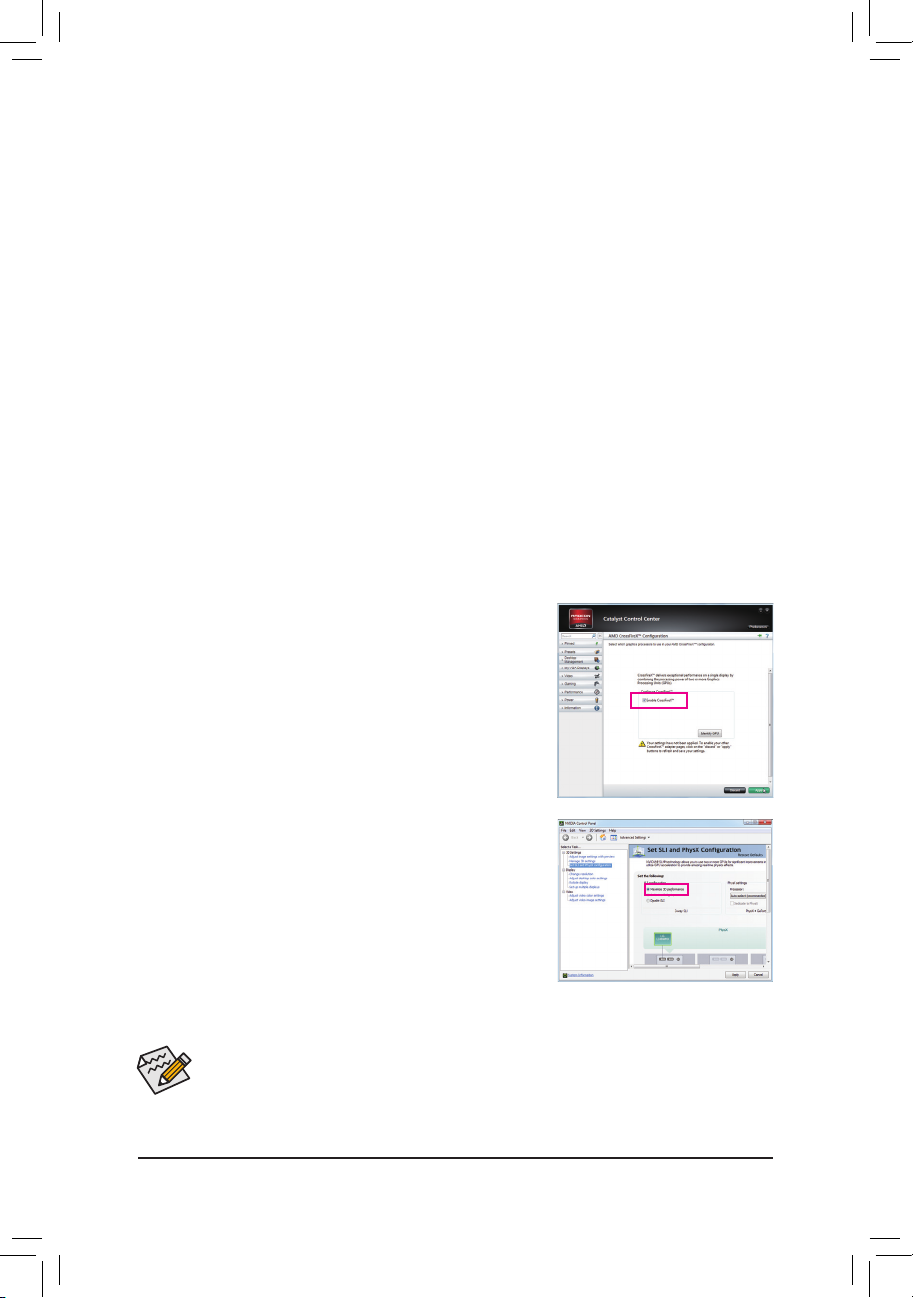
C.ConguringtheGraphicsCardDriver
C-1. To Enable CrossFireX Function
After installing the graphics card driver in the operating system, go to the
Catalyst Control Center. Browse to Performance\AMD CrossFireX™
Conguration and ensure the Enable CrossFireX™ check box is
selected. Then click Apply.
C-2. To Enable SLI Function
After installing the graphics card driver in the operating system, go
to the NVIDIA Control Panel. Browse to the Set SLI and Physx
Conguration screen and ensure Maximize 3D performance is
enabled.
(Note) The bridge connector(s) may be needed or not depending on your graphics cards.
• Procedure and driver screen for enabling CrossFireX/SLI technology may differ by graphics cards
and driver version. Refer to the manual that came with your graphics cards for more information
about enabling CrossFireX/SLI technology.
• When two or more graphics cards are installed, we recommend that you connect the SATA power
cable from the power supply to the ATX4P connector to ensure system stability.
- 20 -
- 9 - Hardware Installation
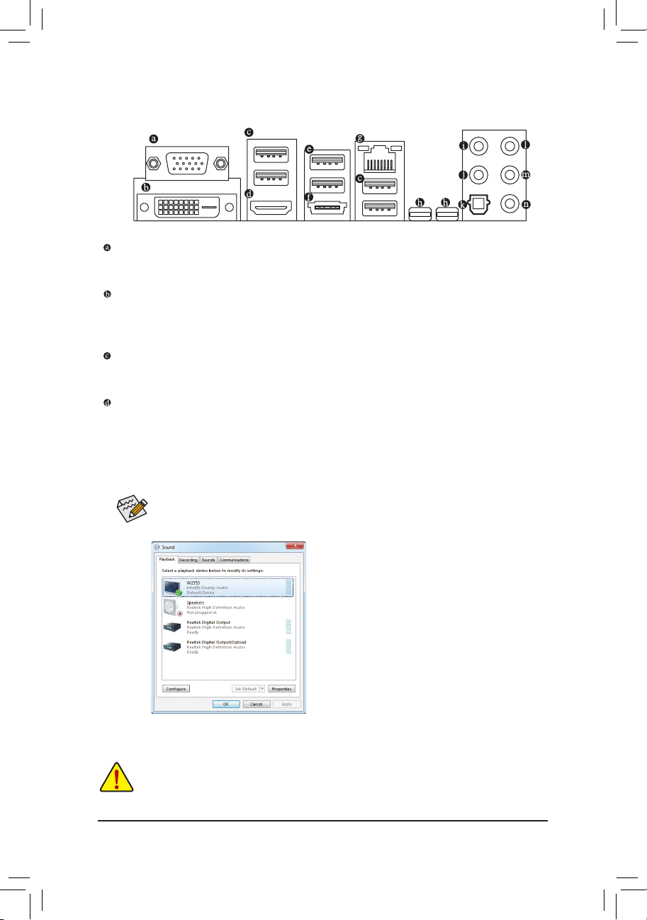
1-7 Back Panel Connectors
D-Sub Port
The D-Sub port supports a 15-pin D-Sub connector. Connect a monitor that supports D-Sub connection
to this port.
DVI-D Port
The DVI-D port conforms to the DVI-D specication and supports a maximum resolution of 1920x1200
(the actual resolutions supported depend on the monitor being used). Connect a monitor that supports
DVI-D connection to this port.
USB 3.0/2.0 Port
The USB 3.0 port supports the USB 3.0 specication and is compatible to the USB 2.0/1.1 specication.
Use this port for USB devices such as a USB keyboard/mouse, USB printer, USB ash drive and etc.
HDMI Port
HDMI (High-Denition Multimedia Interface) is an all-digital audio/video interface capable of transmitting
uncompressed audio/video signals. The HDMI port is HDCP compliant and supports Dolby TrueHD and DTS HD
Master Audio formats. It also supports up to 192KHz/24bit 8-channel LPCM audio output. You can use
this port to connect your HDMI-supported monitor. The maximum supported resolution is 1920x1200, but
the actual resolutions supported are dependent on the monitor being used.
(Note 1)
After installing the HDMI device, make sure to set the default sound playback device to HDMI.
(The item name may differ depending on your operating system. The screenshot below is from
Windows 7.)
In Windows 7, select Start>Control Panel>Hardware and
Sound>Sound>Playback, set Intel(R) Display Audio to the
default playback device.
(Note 1) The DVI-D port does not support D-Sub connection by adapter.
• When removing the cable connected to a back panel connector, rst remove the cable from your
device and then remove it from the motherboard.
• When removing the cable, pull it straight out from the connector. Do not rock it side to side to prevent
an electrical short inside the cable connector.
Hardware Installation
DualDisplayCongurationsfortheOnboardGraphics:
This motherboard provides four video output ports: D-Sub, DVI-D, HDMI, and Thunderbolt. Dual monitor
congurations are supported in operating system environment only, but not during the BIOS Setup or
POST process.
USB 2.0/1.1 Port
The USB 2.0/1.1 port supports the USB 3.0 specication and is compatible to the USB 2.0/1.1 specication.
Use this port for USB devices such as a USB keyboard/mouse, USB printer, USB ash drive and etc.
eSATA 6Gb/s Connector
This connector supports SATA 6Gb/s specication. Use the port to connect an external SATA device or a
SATA port multiplier. The Marvell 88SE9172 chip supports RAID function. Refer to Chapter 5, "Conguring
SATA Hard Drive(s)," for instructions on conguring a RAID array.
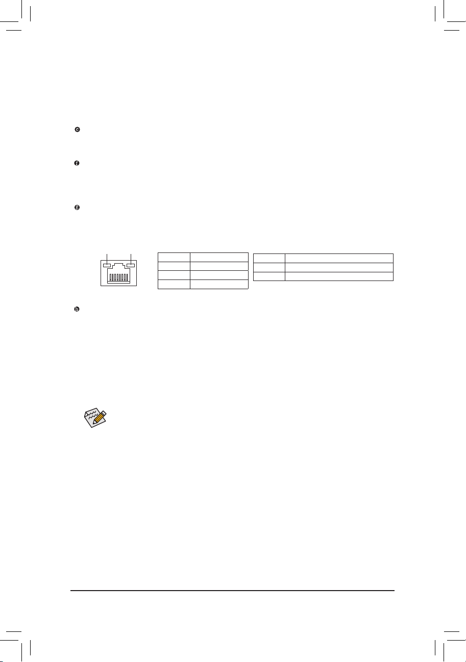
RJ-45 LAN Port
The Gigabit Ethernet LAN port provides Internet connection at up to 1 Gbps data rate. The following
describes the states of the LAN port LEDs.
Connection/
Speed LED
Activity LED
LAN Port
Thunderbolt Port
Use this port for Thunderbolt devices or Mini-DisplayPort monitors. Thunderbolt device connectivity is
dependent on PC I/O resources availability. Each Thunderbolt port can be daisy chain around 3 Thunderbolt
devices. If you need to connect more Thunderbolt devices, adjust Reserved IO for Thunderbolt under
Peripherals\Intel(R) Thunderbolt in BIOS Setup. (Refer to Chapter 2, "Peripherals\Intel(R) Thunderbolt"
for more information.)
This motherboard built-in 2 Thunderbolt ports and support up to 2 DisplayPort monitors. 2 DisplayPort
monitors daisy chain in the same port must separate by one Thunderbolt device. The maximum supported
resolution is 2560x1600, but the actual resolutions supported are dependent on the monitor being used.
After installing the DisplayPort device, make sure the default device for sound playback is the
DisplayPort device. (The item name may differ from operating system. For example, in Windows 7,
go to Start>Control Panel>Hardware and Sound>Sound>Playback and set the DisplayPort device
as the default playback device. Refer to the HDMI settings information on the previous page for
the conguration dialog box.)
Connection/Speed LED:
State Description
Orange 1 Gbps data rate
Green 100 Mbps data rate
Off 10 Mbps data rate
(Note 2)
Activity LED:
State Description
Blinking Data transmission or receiving is occurring
On No data transmission or receiving is occurring
(Note 2) Simultaneous output for DVI-D and the MDP2 Thunderbolt port is not supported. When a monitor
connected to the DVI-D port, the MDP2 Thunderbolt port can support Thunderbolt storage device(s)
only.
- 22 -
- 9 - Hardware Installation
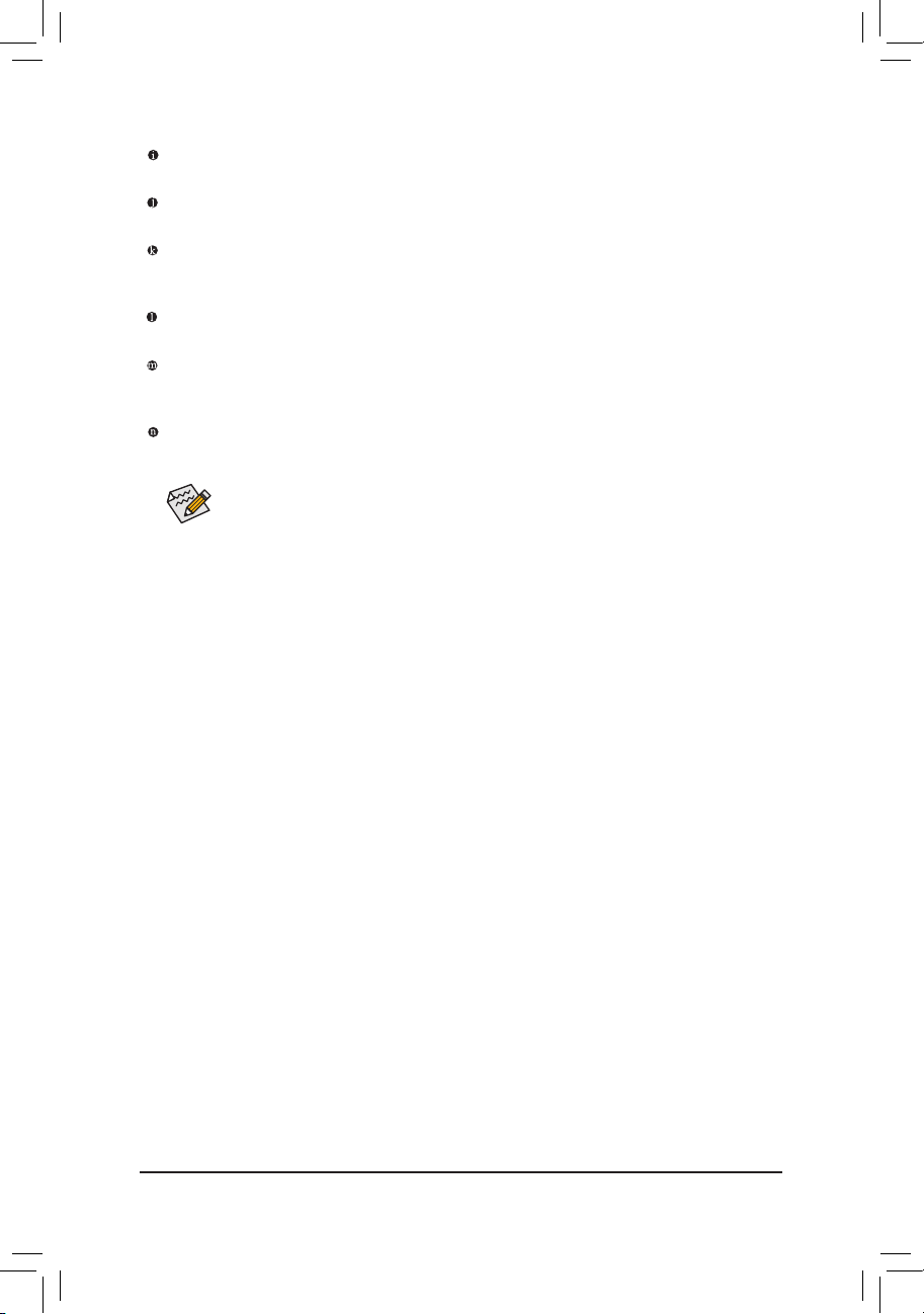
Center/Subwoofer Speaker Out Jack (Orange)
Use this audio jack to connect center/subwoofer speakers in a 5.1/7.1-channel audio conguration.
Rear Speaker Out Jack (Black)
Use this audio jack to connect rear speakers in a 7.1-channel audio conguration.
Optical S/PDIF Out Connector
This connector provides digital audio out to an external audio system that supports digital optical audio.
Before using this feature, ensure that your audio system provides an optical digital audio in connector.
Line In Jack (Blue)
The default line in jack. Use this audio jack for line in devices such as an optical drive, walkman, etc.
Line Out Jack (Green)
The default line out jack. Use this audio jack for a headphone or 2-channel speaker. This jack can be used
to connect front speakers in a 4/5.1/7.1-channel audio conguration.
Mic In Jack (Pink)
The default Mic in jack. Microphones must be connected to this jack.
The audio jacks can be recongured to perform different functions via the audio software. If
you install a Side Speaker, you need to retask other audio jack to be Side Speaker out. Only
microphones still MUST be connected to the default Mic in jack. Refer to the instructions on setting
up a 2/4/5.1/7.1-channel audio conguration in Chapter 5, "Conguring 2/4/5.1/7.1-Channel Audio."
Hardware Installation
1-8 Onboard Buttons, Switches and LEDs
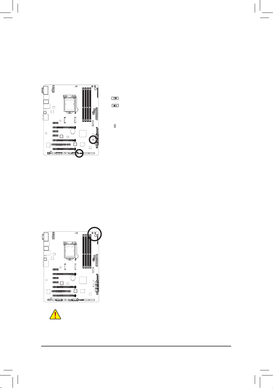
BIOS Switch and BIOS LED Indicators
The BIOS switch (SW4) allows users to easily select a different BIOS for boot up or overclocking, helping to reduce
BIOS failure during overclocking. The LED indicator (MBIOS_LED/BBIOS_LED) shows which BIOS is active.
BIOS Switch:
SW4
1: Main BIOS (Boot from the main BIOS)
3: Backup BIOS (Boot from the backup BIOS)
BIOS LED Indicators:
MBIOS_LED (The main BIOS is active)
BBIOS_LED (The backup BIOS is active)
Quick Buttons
This motherboard has 3 quick buttons: power button, reset button and clearing CMOS button. The power button
and reset button allow users to quickly turn on/off or reset the computer in an open-case environment when they
want to change hardware components or conduct hardware testing. Use this button to clear the CMOS values
(e.g. date information and BIOS conguration) and reset the CMOS values to factory defaults when needed.
PW_SW: Power button
RST_SW: Reset button
CMOS_SW: Clear CMOS Button
• Always turn off your computer and unplug the power cord from the power outlet before clearing
the CMOS values.
• After system restart, go to BIOS Setup to load factory defaults (select Load Optimized Defaults) or
manually congure the BIOS settings (refer to Chapter 2, "BIOS Setup," for BIOS congurations).
- 24 -
- 9 - Hardware Installation
Voltage Measurement Points
F_AUDIO(H)
DB_PORT
F_PANEL(NH) F_PANEL
(H61M-D2)
ACPI_CPT
(GA-IVB)
BIOS_PH
(GA-IVB)
SMB_CPT
(GA-IVB)
CLR_CMOS
CI
DIS_ME
GP15_CPT
(GA-IVB)
XDP_CPU
XDP_PCH
(GA-IVB)
Voltage measurement module(X58A-OC)
PCIe power connector (SATA)(X58A-OC)
DIP
123
DIP
123
DIP
123
DIP
123
1
1
1
1
BIOS Switcher (X58A-OC)
PWM Switch (X58A-OC)
M_SATA
PWM Switch (SW1)(X79-UD7)
DIP
1 2 3 4 5
BIOS Switcher (SW4)
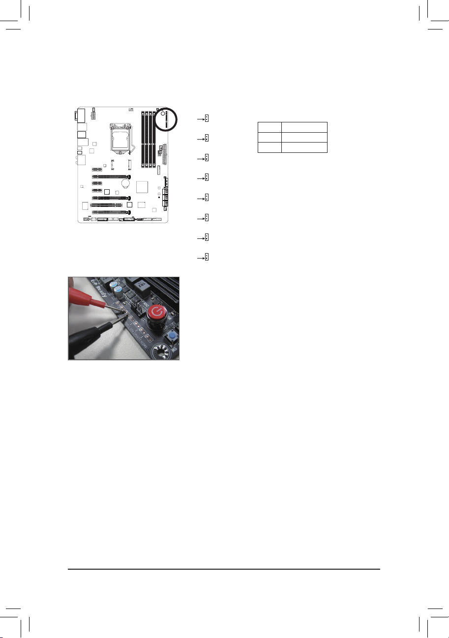
Users can use a multimeter to measure component voltages, including VCORE, CPU VTT, IMC, VAXG, CPUPLL,
DDRVTT, VDIMM, and PCHIO. You can employ following way to measure component voltages.
VCORE
Pin 1
CPUVTT
Pin 1
IMC
Pin 1
VAXG
Pin 1
CPUPLL
Pin 1
DDRVTT
Pin 1
VDIMM
Pin 1
PCHIO
Pin 1
Steps:
Connect the red lead of the multimeter to the pin 1 (Power) of a voltage
measurement point and the black lead to the pin 2 (ground).
Pin No. Denition
1 Power
2 GND
Hardware Installation
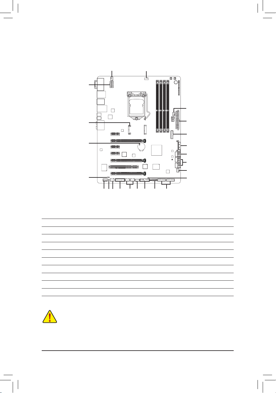
1-9 Internal Connectors
1) ATX_12V_2X4
2) ATX
3) ATX4P
4) CPU_FAN
5) SYS_FAN1/2/3/4
6) SATA3 0/1
7) SATA2 2/3/4/5
8) GSATA3 8
9) mSATA
10) F_PANEL
5
1
9
18
13
17
11
14
13
4
5
2
16
10
6
7
5
19
5
1015
8
16
11) F_AUDIO
12) SPDIF_IN
13) SPDIF_O
14) F_1394
15) F_USB1/F_USB2
16) F_USB30_1/F_USB30_2/F_USB30_3
17) TPM
18) BAT
19) CLR_CMOS
Read the following guidelines before connecting external devices:
• First make sure your devices are compliant with the connectors you wish to connect.
• Before installing the devices, be sure to turn off the devices and your computer. Unplug the power
• After installing the device and before turning on the computer, make sure the device cable has
cord from the power outlet to prevent damage to the devices.
been securely attached to the connector on the motherboard.
- 26 -
- 9 - Hardware Installation
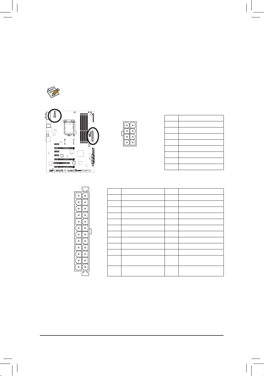
1/2) ATX_12V_2X4/ATX (2x4 12V Power Connector and 2x12 Main Power Connector)
With the use of the power connector, the power supply can supply enough stable power to all the components
on the motherboard. Before connecting the power connector, rst make sure the power supply is turned
off and all devices are properly installed. The power connector possesses a foolproof design. Connect the
power supply cable to the power connector in the correct orientation.
The 12V power connector mainly supplies power to the CPU. If the 12V power connector is not connected,
the computer will not start.
To meet expansion requirements, it is recommended that a power supply that can withstand high
power consumption be used (500W or greater). If a power supply is used that does not provide the
required power, the result can lead to an unstable or unbootable system.
ATX_12V_2X4:
Pin No. Denition
1 GND (Only for 2x4-pin 12V)
2 GND (Only for 2x4-pin 12V)
3 GND
4 GND
5 +12V (Only for 2x4-pin 12V)
6 +12V (Only for 2x4-pin 12V)
7 +12V
8 +12V
23 +5V (Only for 2x12-pin ATX)
24 GND (Only for 2x12-pin
ATX)
ATX
814
5
ATX_12V_2X4
ATX:
2412
131
Pin No. Denition Pin No. Denition
1 3.3V 13 3.3V
2 3.3V 14 -12V
3 GND 15 GND
4 +5V 16 PS_ON (soft On/Off)
5 GND 17 GND
6 +5V 18 GND
7 GND 19 GND
8 Power Good 20 -5V
9 5VSB (stand by +5V) 21 +5V
10 +12V 22 +5V
11 +12V (Only for 2x12-pin
ATX)
12 3.3V (Only for 2x12-pin
ATX)
Hardware Installation
DEBUG
PORT
CLR_CMOSCIDIS_ME
GP15_CPT
(GA-IVB)
XDP_CPU
XDP_PCH
(GA-IVB)
BIOS Switcher (SW4)
DEBUG
PORT
3) ATX4P (PCIe Power Connector)
The power connector provide auxiliary power to the onboard PCI Express x16 slots. When two or more
graphics cards are installed, we recommend that you connect the SATA power cable(s) from the power
supply to the ATX4P connector to ensure system stability.
Pin No. Denition
1 NC
2 NC
1
15
3 NC
4 GND
5 GND
GND
6
7 VCC
8 VCC
9 VCC
GND
10
11 GND
12 GND
13 +12V
14 +12V
15 +12V
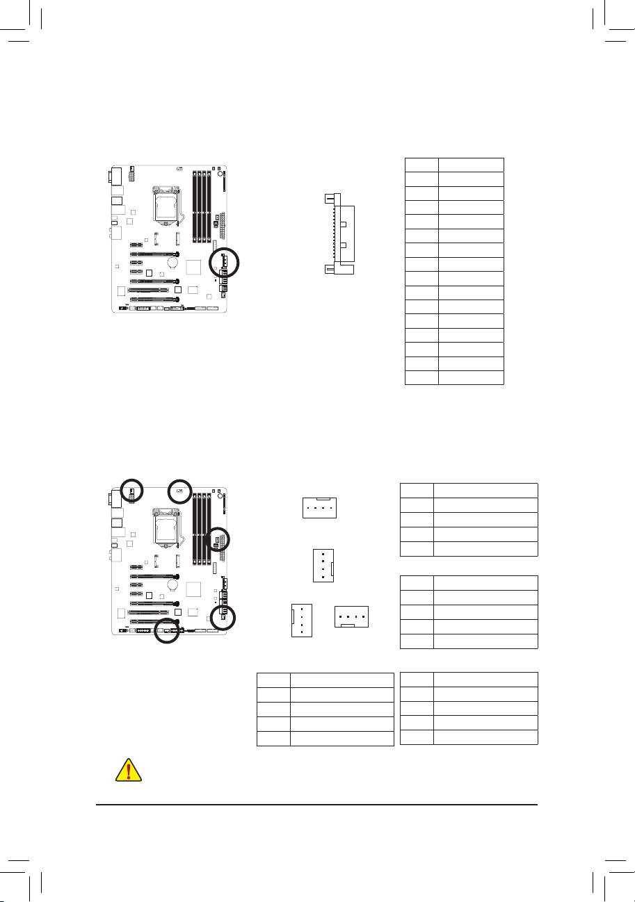
4/5) CPU_FAN/SYS_FAN1/SYS_FAN2/SYS_FAN3/SYS_FAN4 (Fan Headers)
All fan headers on this motherboard are 4-pin. Most fan headers possess a foolproof insertion design.
When connecting a fan cable, be sure to connect it in the correct orientation (the black connector wire is
the ground wire). The speed control function requires the use of a fan with fan speed control design. For
optimum heat dissipation, it is recommended that a system fan be installed inside the chassis.
CPU_FAN:
Pin No. Denition
1 GND
2 +12V /Speed Control
3 Sense
4 Speed Control
SYS_FAN1:
Pin No. Denition
1 GND
2 +12V /Speed Control
3 Sense
4 VCC
SYS_FAN4:
Pin No. Denition
1 GND
2 +12V
3 Sense
4 Reserve
1
CPU_FAN
SYS_FAN1/SYS_FAN2
1
SYS_FAN3
SYS_FAN2/3:
1
1
SYS_FAN4
Pin No. Denition
1 GND
2 +12V
3 Sense
4 Speed Control
• Be sure to connect fan cables to the fan headers to prevent your CPU and system from
overheating. Overheating may result in damage to the CPU or the system may hang.
• These fan headers are not conguration jumper blocks. Do not place a jumper cap on the headers.
- 28 -
- 9 - Hardware Installation
G.QBOFM
G.QBOFM
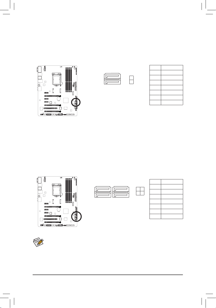
6) SATA3 0/1 (SATA 6Gb/s Connectors, Controlled by Intel Z77 Chipset)
G.QBOFM
The SATA connectors conform to SATA 6Gb/s standard and are compatible with SATA 3Gb/s and SATA
1.5Gb/s standard. Each SATA connector supports a single SATA device. The SATA3 0/1 connectors support
RAID 0 and RAID 1. RAID 5 and RAID 10 can be implemented on the two connectors with the "SATA2
2/3/4/5" and mSATA connectors
(Note)
. Refer to Chapter 5, "Conguring SATA Hard Drive(s)," for instructions
on conguring a RAID array.
SATA 3
7 1
7 1
1
0
Pin No. Denition
1 GND
2 TXP
3 TXN
4 GND
5 RXN
6 RXP
7 GND
7) SATA2 2/3/4/5 (SATA 3Gb/s Connectors, Controlled by Intel Z77 Chipset)
The SATA connectors conform to SATA 3Gb/s standard and are compatible with SATA 1.5Gb/s standard.
Each SATA connector supports a single SATA device. The Intel Z77 Chipset supports RAID 0, RAID 1,
RAID 5, and RAID 10. Refer to Chapter 5, "Conguring SATA Hard Drive(s)," for instructions on conguring
a RAID array.
SATA 2
7
7
1
1
5 3
4 2
Pin No. Denition
1 GND
2 TXP
3 TXN
4 GND
5 RXN
6 RXP
7 GND
• A RAID 0 or RAID 1 conguration requires at least two hard drives. If more than two hard drives
are to be used, the total number of hard drives must be an even number.
• A RAID 5 conguration requires at least three hard drives. (The total number of hard drives does
not have to be an even number.)
• A RAID 10 conguration requires four hard drives.
(Note) When a RAID set is built across the SATA 6Gb/s and SATA 3Gb/s channels, the system performance
of the RAID set may vary depending on the devices being connected.
Hardware Installation
SMB_CPT
(GA-IVB)
CLR_CMOSCIDIS_ME
GP15_CPT
(GA-IVB)
XDP_CPU
XDP_PCH
(GA-IVB)
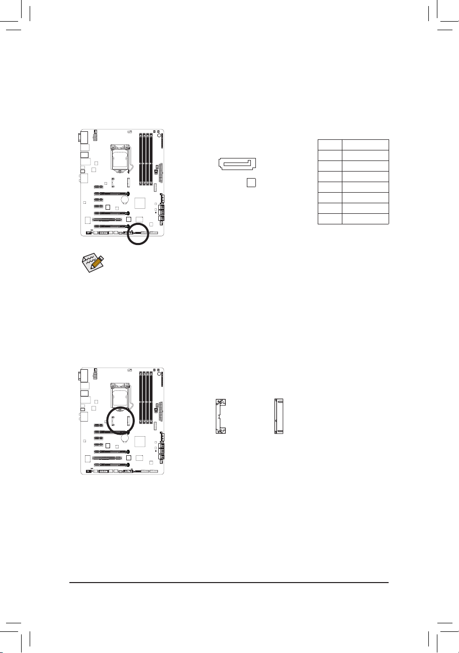
8) GSATA3 8 (SATA 6Gb/s Connector, Controlled by Marvell 88SE9172 Chip)
DEBUG
PORT
G.QBOFM
The SATA connector conforms to SATA 6Gb/s standard and are compatible with SATA 3Gb/s and SATA
1.5Gb/s standard. Each SATA connector supports a single SATA device. The Marvell 88SE9172 chip
supports RAID 0 and RAID 1. Refer to Chapter 5, "Conguring SATA Hard Drive(s)," for instructions on
conguring a RAID array.
Pin No. Denition
1 GND
1
GSATA3
7
8
2 TXP
3 TXN
4 GND
5 RXN
6 RXP
7 GND
A RAID 0 or RAID 1 conguration requires at least two hard drives.
9) mSATA (Solid-State Drive Connector, Controlled by the Intel Z77 Chipset)
The mSATA connector conforms to SATA 3Gb/s standard and can connect to a single solid-state drive. When
the mSATA connector is installed with a solid-state drive, the SATA2_5 connector will become unavailable.
mS ATA
- 30 -
 Loading...