

Page 1

GA-Z77-D3H
GA-H77-D3H-MVP
GA-H77-D3H
User's Manual
Rev. 1002
12M E-Z77D3H-1002R
Page 2
Motherboard
Feb. 8, 2012
Feb. 8, 2012
Motherboard
GA-Z77-D3H/GA-H77-D3H-MVP/GA-H77-D3H
GA-Z77-D3H/
GA-H77-D3H-MVP/
GA-H77-D3H
Page 3
Copyright
© 2012 GIGA-BYTE TECHNOLOGY CO., LTD. All rights reserved.
The trademarks mentioned in this manual are legally registered to their respective owners.
Disclaimer
Information in this manual is protected by copyright laws and is the property of GIGABYTE.
Changes to the specications and features in this manual may be made by GIGABYTE
without prior notice. No part of this manual may be reproduced, copied, translated, transmit-
ted, orpublished in any form or by any means without GIGABYTE's prior written permission.
Documentation Classications
In order to assist in the use of this product, GIGABYTE provides the following types of
documentations:
For quick set-up of the product, read the Quick Installation Guide included with the product.
For detailed product information, carefully read the User's Manual.
For product-related information, check on our website at: http://www.gigabyte.com
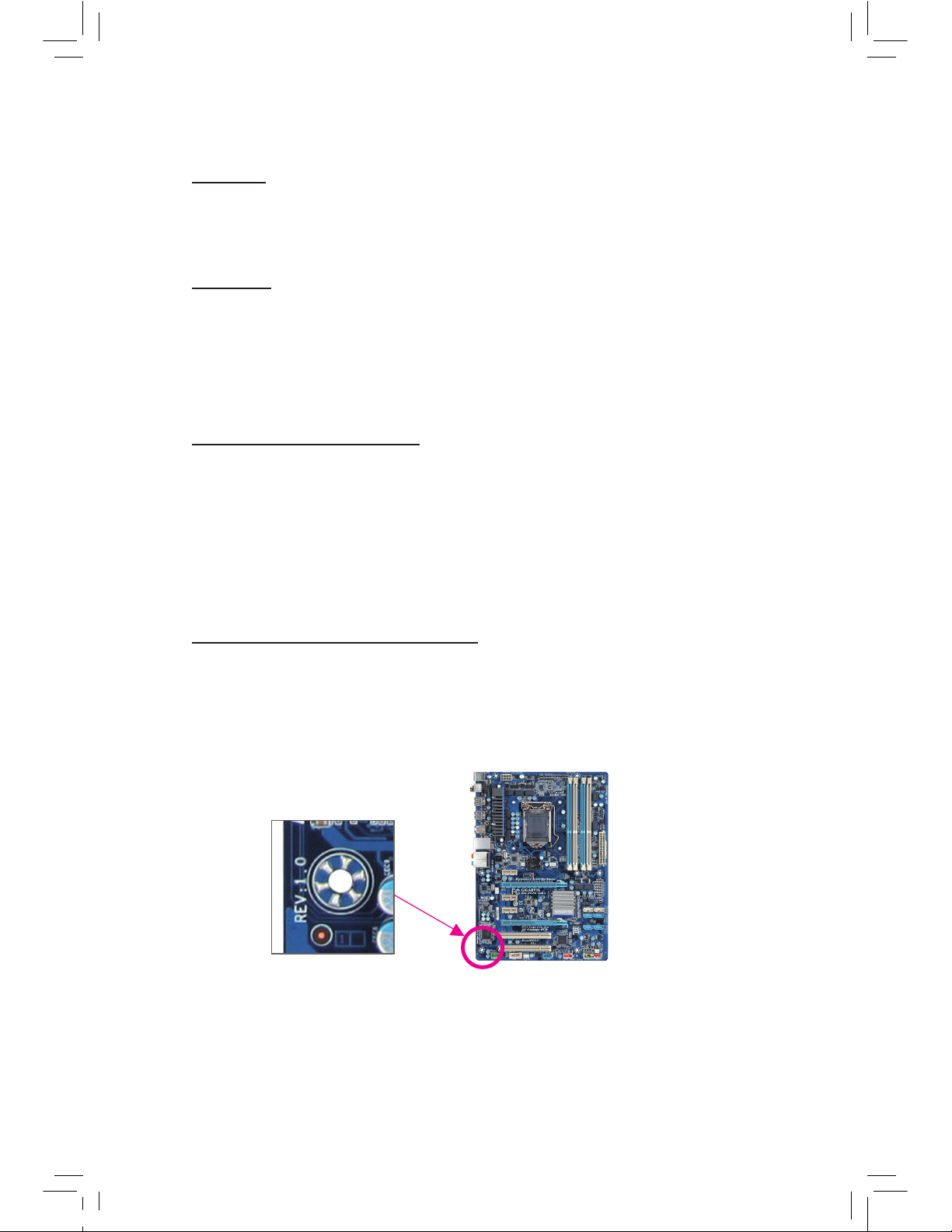
Identifying Your Motherboard Revision
The revision number on your motherboard looks like this: "REV: X.X." For example, "REV:
1.0" means the revision of the motherboard is 1.0. Check your motherboard revision before
updating motherboard BIOS, drivers, or when looking for technical information.
Example:
Page 4

- 4 -
Table of Contents
Box Contents ...................................................................................................................6
Optional Items .................................................................................................................6
GA-Z77-D3H/GA-H77-D3H-MVP/GA-H77-D3H Motherboard Layout
...........................7
GA-Z77-D3H/GA-H77-D3H-MVP/GA-H77-D3H Motherboard Block Diagram ...............8
Chapter 1 Hardware Installation .....................................................................................9
1-1 Installation Precautions ................................................................................... 9
1-2 Product Specications ................................................................................... 10
1-3 Installing the CPU and CPU Cooler............................................................... 13
1-3-1 Installing the CPU ..................................................................................................13
1-3-2 Installing the CPU Cooler ......................................................................................15
1-4 Installing the Memory .................................................................................... 16
1-4-1 Dual Channel Memory Conguration ........................................................................16
1-4-2 Installing a Memory ................................................................................................17
1-5 Installing an Expansion Card ......................................................................... 18
1-6 Back Panel Connectors ................................................................................. 19
1-7 Internal Connectors ....................................................................................... 21
Chapter 2 BIOS Setup ..................................................................................................31
2-1 Startup Screen ............................................................................................... 32
2-2 The Main Menu .............................................................................................. 33
2-3 M.I.T. ..............................................................................................................35
2-4 System ........................................................................................................... 45
2-5 BIOS Features ...............................................................................................46
2-6 Peripherals ..................................................................................................... 48
2-7 Power Management ....................................................................................... 52
2-8 Save & Exit .................................................................................................... 54
Page 5

- 5 -
Chapter 3 Drivers Installation .......................................................................................55
3-1 Installing Chipset Drivers ............................................................................... 55
3-2 Application Software ......................................................................................56
3-3 Technical Manuals ......................................................................................... 56
3-4 Contact........................................................................................................... 57
3-5 System ........................................................................................................... 57
3-6 Download Center ........................................................................................... 58
3-7 New Program ................................................................................................. 58
Chapter 4 Unique Features ...........................................................................................59
4-1 Xpress Recovery2 .......................................................................................... 59
4-2 BIOS Update Utilities ..................................................................................... 62
4-2-1 Updating the BIOS with the Q-Flash Utility ...........................................................62
4-2-2 Updating the BIOS with the @BIOS Utility ........................................................... 65
4-3 EasyTune 6 .................................................................................................... 66
4-4 Q-Share .........................................................................................................67
4-5 eXtreme Hard Drive (X.H.D) .......................................................................... 68
4-6 Auto Green .....................................................................................................69
4-7 Intel Rapid Start Technology ......................................................................... 70
4-8 Intel Smart Connect Technology ................................................................... 72
4-9 Intel Smart Response .................................................................................... 74
Chapter 5 Appendix ......................................................................................................77
5-1 Conguring SATA Hard Drive(s) .................................................................... 77
5-1-1 Conguring SATA Controllers ................................................................................77
5-1-2 Installing the SATA RAID/AHCI Driver and Operating System ............................ 85
5-2 Conguring Audio Input and Output .............................................................. 90
5-2-1 Conguring 2/4/5.1/7.1-Channel Audio ................................................................. 90
5-2-2 Conguring S/PDIF Out .........................................................................................92
5-2-3 Conguring Microphone Recording .......................................................................93
5-2-4 Using the Sound Recorder ................................................................................... 95
5-3 Troubleshooting ............................................................................................. 96
5-3-1 Frequently Asked Questions ................................................................................ 96
5-3-2 Troubleshooting Procedure ...................................................................................97
5-3-3 Regulatory Statements ......................................................................................... 99
Page 6
- 6 -
Optional Items
2-port USB 2.0 bracket (Part No. 12CR1-1UB030-5*R)
2-port SATA power cable (Part No. 12CF1-2SERPW-0*R)
COM port cable (Part No. 12CF1-1CM001-3*R)
3.5" Front Panel with 2 USB 3.0/2.0 ports (Part No. 12CR1-FPX582-0*R)
The box contents above are for reference only and the actual items shall depend on the product package you obtain.
The box contents are subject to change without notice.
Box Contents
GA-Z77-D3H, GA-H77-D3H-MVP or GA-H77-D3H motherboard
Motherboard driver disk
User's Manual
Quick Installation Guide
Two SATA 6Gb/s cables
Two SATA 3Gb/s cables
I/O Shield
Page 7
- 7 -
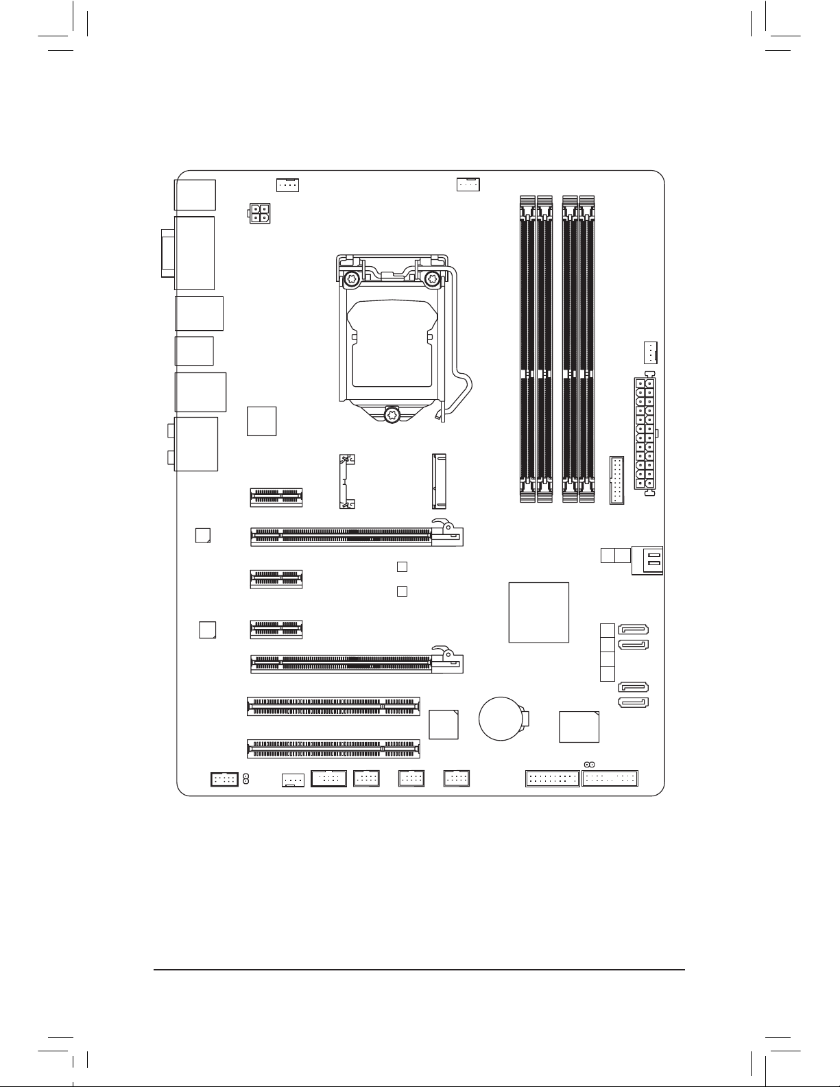
GA-Z77-D3H/GA-H77-D3H-MVP/GA-H77-D3H Motherboard Layout
KB_MS_USB
CPU_FAN
ATX_12V
ATX
F_AUDIO
AUDIO
B_BIOS
PCIEX4
DDR3_2
DDR3_1
DDR3_4
DDR3_3
BAT
F_PANEL
COMA
Intel
®
Z77
j
Intel® H77
kl
PCI2
CLR_CMOS
CODEC
SYS_FAN2
M_BIOS
PCIEX1_2
PCIEX16
SPDIF_O
F_USB1
LGA1155
DVI VGA
HDMI
R_USB30_2
R_USB30_1
USB_LAN
A t h er o s
GbE LAN
PCI1
F_USB30
PCIEX1_3
PCIe to PCI
Bridge
SYS_FAN3
SATA3
iTE
Super I/O
SYS_FAN1
F_USB2
F_USB3
Etron
EJ168
mSATA
TPM
PCIEX1_1
1
0
2345
SATA2
j
Only for GA-Z77-D3H.
k
Only for GA-H77-D3H-MVP.
l
Only for GA-H77-D3H.
GA-Z77-D3H/GA-H77-D3H-MVP/
GA-H77-D3H
Page 8
- 8 -
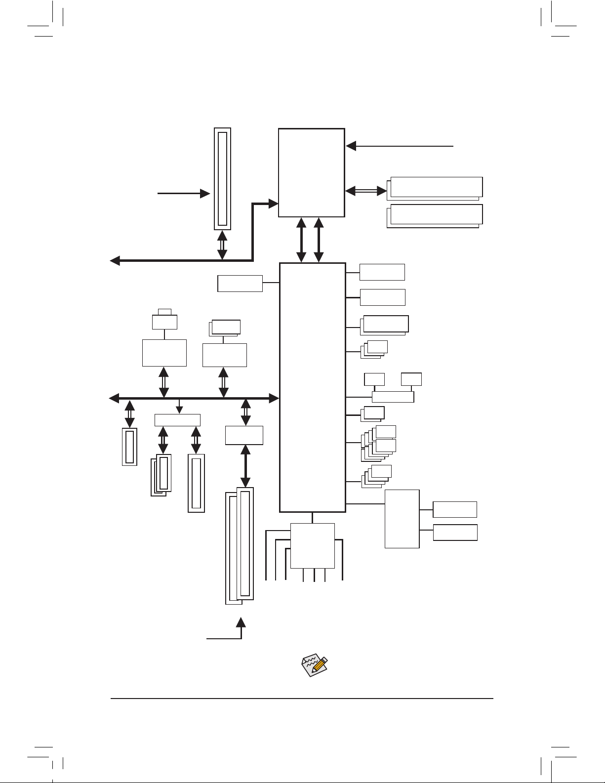
GA-Z77-D3H/GA-H77-D3H-MVP/GA-H77-D3H
Motherboard Block Diagram
Center/Subwoofer Speaker Out
Line Out
MIC
Line In
S/PDIF Out
Side Speaker Out
Surround Speaker Out
PS/2 KB/Mouse
LGA1155
CPU
DMI 2.0
FDI
CPU CLK+/- (100 MHz)
Dual BIOS
HDMI
10 USB 2.0/1.1
DDR3 1600/1333/1066 MHz
Dual Channel Memory
COM Port
LPC Bus
Intel® Z77
j
Intel
®
H77
kl
x1
2 USB 3.0/2.0
Etron
EJ168
iTE
Super
I/O
CODEC
PCIe CLK
(100 MHz)
PCI Express Bus
1 PCI Express x16
x1
LAN
RJ45
Atheros
GbE LAN
2 PCI
PCI Bus
PCI CLK
(33 MHz)
PCIe to PCI
Bridge
x1
Switch
or
x1
2 PCI Express x1
x4
1 PCI Express x4
PCI Express Bus
x16
D-Sub
DVI-D
4 USB 3.0/2.0
2 SATA 6Gb/s
1 SATA 3Gb/s
or
1 mSATA
3 SATA 3Gb/s
Switch
j
Only for GA-Z77-D3H.
k
Only for GA-H77-D3H-MVP.
l
Only for GA-H77-D3H.
x1
1 PCI Express x1
For detailed product information/limitation(s),
refer to "1-2 Product Specications."
Page 9

- 9 - Hardware Installation
1-1 Installation Precautions
The motherboard contains numerous delicate electronic circuits and components which can
become damaged as a result of electrostatic discharge (ESD). Prior to installation, carefully read
the user's manual and follow these procedures:
Prior to installation, make sure the chassis is suitable for the motherboard.
•
Prior to installation, do not remove or break motherboard S/N (Serial Number) sticker or
•
warranty sticker provided by your dealer. These stickers are required for warranty validation.
Always remove the AC power by unplugging the power cord from the power outlet before
•
installing or removing the motherboard or other hardware components.
When connecting hardware components to the internal connectors on the motherboard,
•
make sure they are connected tightly and securely.
When handling the motherboard, avoid touching any metal leads or connectors.
•
It is best to wear an electrostatic discharge (ESD) wrist strap when handling electronic com-
•
ponents such as a motherboard, CPU or memory. If you do not have an ESD wrist strap,
keep your hands dry and rst touch a metal object to eliminate static electricity.
Prior to installing the motherboard, please have it on top of an antistatic pad or within an
•
electrostatic shielding container.
Before unplugging the power supply cable from the motherboard, make sure the power sup-
•
ply has been turned off.
Before turning on the power, make sure the power supply voltage has been set according to
•
the local voltage standard.
Before using the product, please verify that all cables and power connectors of your hard-
•
ware components are connected.
To prevent damage to the motherboard, do not allow screws to come in contact with the
•
motherboard circuit or its components.
Make sure there are no leftover screws or metal components placed on the motherboard or
•
within the computer casing.
Do not place the computer system on an uneven surface.
•
Do not place the computer system in a high-temperature environment.
•
Turning on the computer power during the installation process can lead to damage to sys-
•
tem components as well as physical harm to the user.
If you are uncertain about any installation steps or have a problem related to the use of the
•
product, please consult a certied computer technician.
Chapter 1 Hardware Installation
Page 10
- 10 -Hardware Installation
1-2 Product Specications
CPU Support for Intel
®
Core™ i7 processors/Intel® Core™ i5 processors/
Intel® Core™ i3 processors/Intel® Pentium® processors/
Intel® Celeron® processors in the LGA1155 package
(Go to GIGABYTE's website for the latest CPU support list.)
L3 cache varies with CPU
Chipset Intel
®
Z77j/Intel® H77kl Express Chipset
Memory 4 x 1.5V DDR3 DIMM sockets supporting up to 32 GB of system memory
* Due to Windows 32-bit operating system limitation, when more than 4 GB of physical
memory is installed, the actual memory size displayed will be less than 4 GB.
Dual channel memory architecture
Support for DDR3 1600/1333/1066 MHz memory modules
* To support DDR3 1600 MHz, you must install an Intel 22nm (Ivy Bridge) CPU.kl
Support for non-ECC memory modules
Support for Extreme Memory Prole (XMP) memory modules
* To support XMP memory, you must install an Intel 22nm (Ivy Bridge) CPU. kl
(Go to GIGABYTE's website for the latest supported memory speeds and memory
modules.)
Onboard
Graphics
Integrated Graphics Processor:
- 1 x D-Sub port
- 1 x DVI-D port, supporting a maximum resolution of 1920x1200
* The DVI-D port does not support D-Sub connection by adapter.
- 1 x HDMI port, supporting a maximum resolution of 1920x1200
Audio VIA VT2021 codec
High Denition Audio
2/4/5.1/7.1-channel
Support for S/PDIF Out
LAN Atheros GbE LAN chip (10/100/1000 Mbit)
Expansion Slots 1 x PCI Express x16 slot, running at x16 (PCIEX16)
(The PCIEX16 slot conforms to PCI Express 3.0 standard.)
* For optimum performance, if only one PCI Express graphics card is to be installed,
be sure to install it in the PCIEX16 slot.
*
To support PCI Express 3.0, you must install an Intel 22nm (Ivy Bridge) CPU.
1 x PCI Express x16 slot, running at x4 (PCIEX4)
* The PCIEX4 slot shares bandwidth with the PCIEX1_2/3 slots. The PCIEX1_2/3 slots
will become unavailable when a PCIe x4 expansion card is installed.
3 x PCI Express x1 slots
(PCIEX4 and PCIEX1 slots conform to PCI Express 2.0 standard.)
2 x PCI slots
Multi-Graphics
Technology
Support for AMD CrossFireX™ technology
* The PCIEX16 slot operates at up to x4 mode when AMD CrossFireX™ is enabled.
j
Only for GA-Z77-D3H.
k
Only for GA-H77-D3H-MVP.
l
Only for GA-H77-D3H.
Page 11

- 11 - Hardware Installation
Storage Interface Chipset:
- 2 x SATA 6Gb/s connectors (SATA3 0/SATA3 1) supporting up to 2 SATA
6Gb/s devices
- 4 x SATA 3Gb/s connectors (SATA2 2~SATA2 5) supporting up to 4 SATA
3Gb/s devices
- 1 x mSATA connector
* The SATA2 5 connector will become unavailable when the mSATA connector is
installed with a solid state drive.
- Support for RAID 0, RAID 1, RAID 5, and RAID 10
* When a RAID set is built across the SATA 6Gb/s and SATA 3Gb/s channels, the system
performance of the RAID set may vary depending on the devices being connected.
USB Chipset:
- Up to 4 USB 3.0/2.0 ports (2 ports on the back panel, 2 ports available through
the internal USB headers)
* In Windows XP, the Intel USB 3.0 ports can support up to USB 2.0 transfer speed.
- Up to 10 USB 2.0/1.1 ports (4 ports on the back panel, 6 ports available
through the internal USB headers)
Etron EJ168 chips:
- Up to 2 USB 3.0/2.0 ports on the back panel
Internal
Connectors
1 x 24-pin ATX main power connector
1 x 4-pin ATX 12V power connector
2 x SATA 6Gb/s connectors
4 x SATA 3Gb/s connectors
1 x mSATA connector
1 x CPU fan header
3 x system fan headers
1 x front panel header
1 x front panel audio header
1 x S/PDIF Out header
1 x USB 3.0/2.0 header
3 x USB 2.0/1.1 headers
1 x serial port header
1 x Clear CMOS jumper
1 x Trusted Platform Module (TPM) header
Back Panel
Connectors
1 x PS/2 keyboard/mouse port
1 x D-Sub port
1 x DVI-D port
1 x HDMI port
4 x USB 3.0/2.0 ports
4 x USB 2.0/1.1 ports
1 x RJ-45 port
1 x optical S/PDIF Out connector
5 x audio jacks (Center/Subwoofer Speaker Out, Rear Speaker
Out, Side Speaker Out, Line In/Mic In, Line Out)
Page 12
- 12 -Hardware Installation
I/O Controller iTE I/O Controller Chip
Hardware
Monitor
System voltage detection
CPU/System temperature detection
CPU/System fan speed detection
CPU overheating warning
CPU/System fan fail warning
CPU/System fan speed control
* Whether the CPU/system fan speed control function is supported will depend on the
CPU/system cooler you install.
BIOS 2 x 64 Mbit ash
Use of licensed AMI EFI BIOS
Support for DualBIOS™
PnP 1.0a, DMI 2.0, SM BIOS 2.6, ACPI 2.0a
Unique Features Support for @BIOS
Support for Q-Flash
Support for Xpress Install
Support for Xpress Recovery2
Support for EasyTune
* Available functions in EasyTune may differ by motherboard model.
Support for eXtreme Hard Drive (X.H.D)
Support for Auto Green
Support for ON/OFF Charge
Support for Q-Share
Support for 3D Power
Support for EZ Setup
Bundled
Software
Norton Internet Security (OEM version)
Intel
®
Rapid Start Technology
Intel
®
Smart Connect Technology
Intel
®
Smart Response Technology
LucidLogix Virtu MVP jk
* Make sure the monitor cable has been connected to the integrated graphics port on
the back panel.
Operating
System
Support for Microsoft
®
Windows 7/XP
Form Factor ATX Form Factor; 30.5cm x 24.4cm
* GIGABYTE reserves the right to make any changes to the product specications and product-related information
without prior notice.
j
Only for GA-Z77-D3H.
k
Only for GA-H77-D3H-MVP.
Page 13
- 13 - Hardware Installation
1-3 Installing the CPU and CPU Cooler
Read the following guidelines before you begin to install the CPU:
Make sure that the motherboard supports the CPU.
•
(Go to GIGABYTE's website for the latest CPU support list.)
Always turn off the computer and unplug the power cord from the power outlet before installing
•
the CPU to prevent hardware damage.
Locate the pin one of the CPU. The CPU cannot be inserted if oriented incorrectly. (Or you may
•
locate the notches on both sides of the CPU and alignment keys on the CPU socket.)
Apply an even and thin layer of thermal grease on the surface of the CPU.
•
Do not turn on the computer if the CPU cooler is not installed, otherwise overheating and dam-
•
age of the CPU may occur.
Set the CPU host frequency in accordance with the CPU specications. It is not recommended
•
that the system bus frequency be set beyond hardware specications since it does not meet the
standard requirements for the peripherals. If you wish to set the frequency beyond the standard
specications, please do so according to your hardware specications including the CPU, graphics card, memory, hard drive, etc.
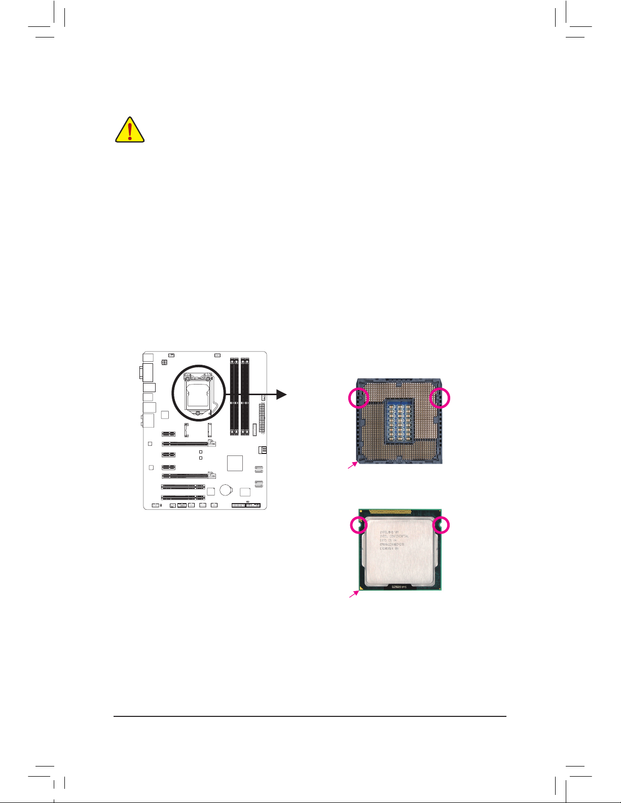
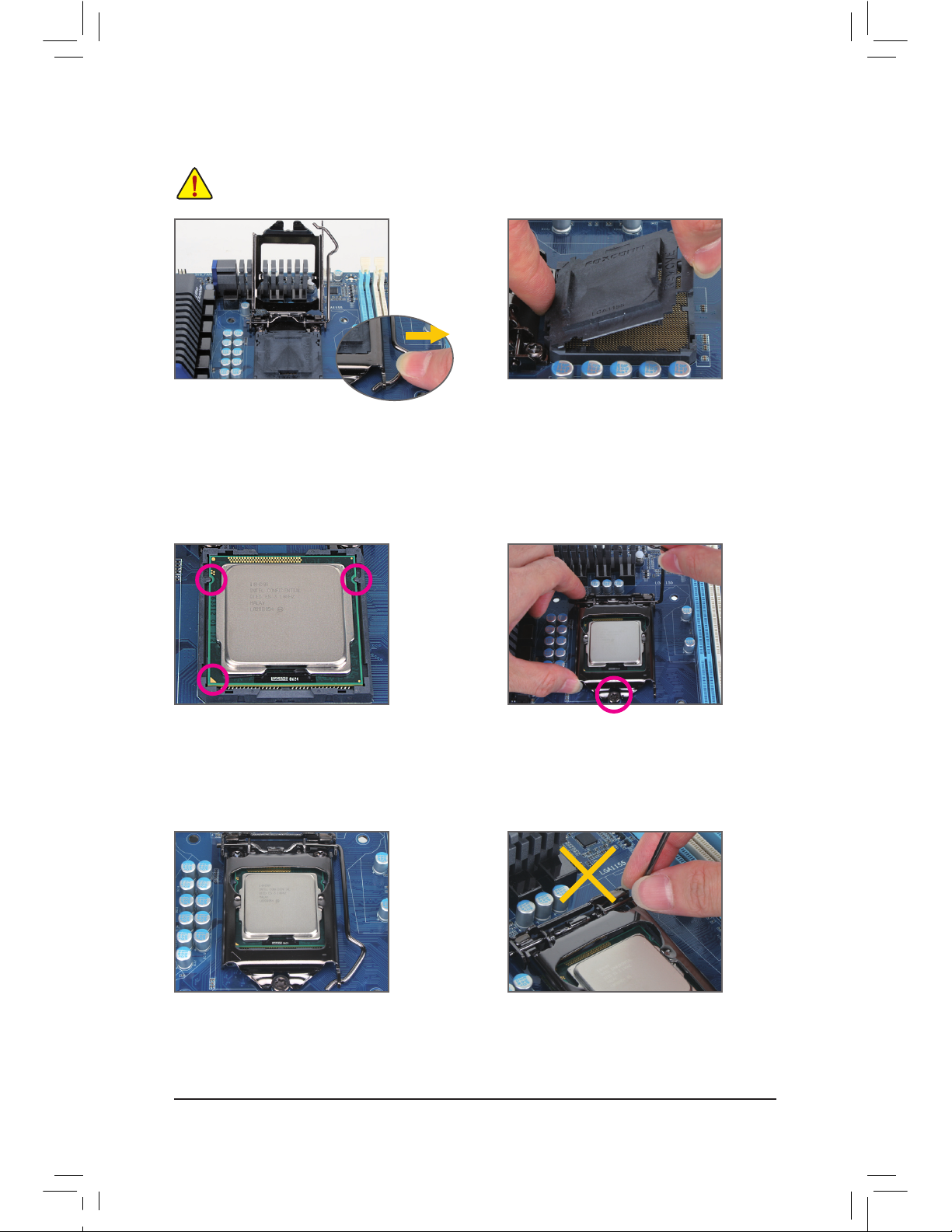
1-3-1 Installing the CPU
A. Locate the alignment keys on the motherboard CPU socket and the notches on the CPU.
Notch
Alignment KeyAlignment Key
Notch
LGA1155 CPU
LGA11
55 CPU Socket
Pin One Corner of the CPU Socket
Triangle Pin One Marking on the CPU
Page 14
- 14 -Hardware Installation
B. F
ollow the steps below to correctly install the CPU into the motherboard CPU socket.
Before installing the CPU, make sure to turn off the computer and unplug the power cord from
the power outlet to prevent damage to the CPU.
Step 1:
Gently p
ress the CPU socket lever handle down
and away from the socket with your nger. Then
completely lift the CPU socket lever and the
metal load plate will be lifted as well.
Step 3:
Ho
ld the CPU with your thumb and index ngers.
Align the CPU pin one marking (triangle) with the
pin one corner of the CPU socket (or you may
align the CPU notches with the socket alignment
keys) and gently insert the CPU into position.
Step 5:
Push t
he CPU socket lever back into its locked
position.
Step 4:
Once
the CPU is properly inserted, use one
hand to hold the socket lever and use the other
to lightly replace the load plate. When replacing
the load plate, make sure the front end of the
load plate is under the shoulder screw.
NOTE:
Ho
ld the CPU socket lever by the handle, not the
lever base portion.
Step 2:
Remove the CPU socket cover as shown. Hold
your index finger down on the rear grip of the
socket cover and use your thumb to lift up the
front edge (next to the "REMOVE" mark) and
then remove the cover. (DO NOT touch socket
contacts. To protect the CPU socket, always replace the protective socket cover when the CPU
is not installed.)
Page 15
- 15 - Hardware Installation
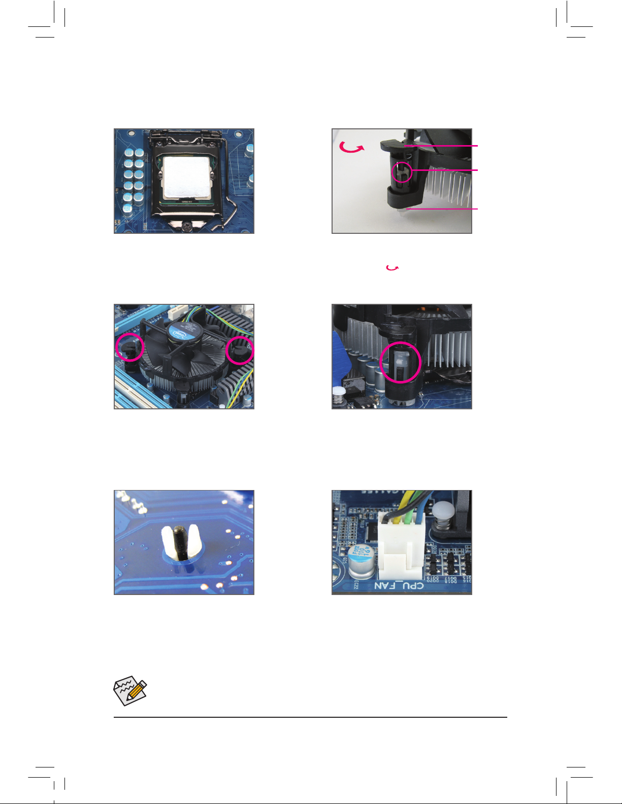
1-3-2 Installing the CPU Cooler
Follow the steps below to correctly install the CPU cooler on the motherboard. (The following procedure uses
Intel® boxed cooler as the example cooler.)
Use e
xtreme care when removing the CPU cooler because the thermal grease/tape between the
CPU cooler and CPU may adhere to the CPU. Inadequately removing the CPU cooler may damage
the CPU.
Step 1:
Apply an even and thin layer of thermal grease
on the surface of the installed CPU.
Male Push
Pin
Female
Push Pin
The Top of
Female
Push Pin
Direction of the
Arrow Sign on
the Male Push
Pin
Step 2:
Before installing the cooler, note the direction of
the arrow sign on the male push pin. (Turning the push pin along the direction of arrow is to
remove the cooler, on the contrary, is to install.)
Step 3:
Place t
he cooler atop the CPU, aligning the four
push pins through the pin holes on the motherboard. Push down on the push pins diagonally.
Step 4:
You should hear a "click" when pushing down
each push pin. Check that the Male and Female
push pins are joined closely.
(Refer to your CPU cooler installation manual for
instructions on installing the cooler.)
Step 5:
After the installation, check the back of the motherboard. If the push pin is inserted as the picture
above shows, the installation is complete.
Step 6:
Finally, attach the power connector of the CPU
cooler to the CPU fan header (CPU_FAN) on the
motherboard.
Page 16
- 16 -Hardware Installation
1-4 Installing the Memory
Read the following guidelines before you begin to install the memory:
Make sure that the motherboard supports the memory. It is recommended that memory of the
•
same capacity, brand, speed, and chips be used.
(Go to GIGABYTE's website for the latest supported memory speeds and memory modules.)
Always turn off the computer and unplug the power cord from the power outlet before installing
•
the memory to prevent hardware damage.
Memory modules have a foolproof design. A memory module can be installed in only one direc-
•
tion. If you are unable to insert the memory, switch the direction.
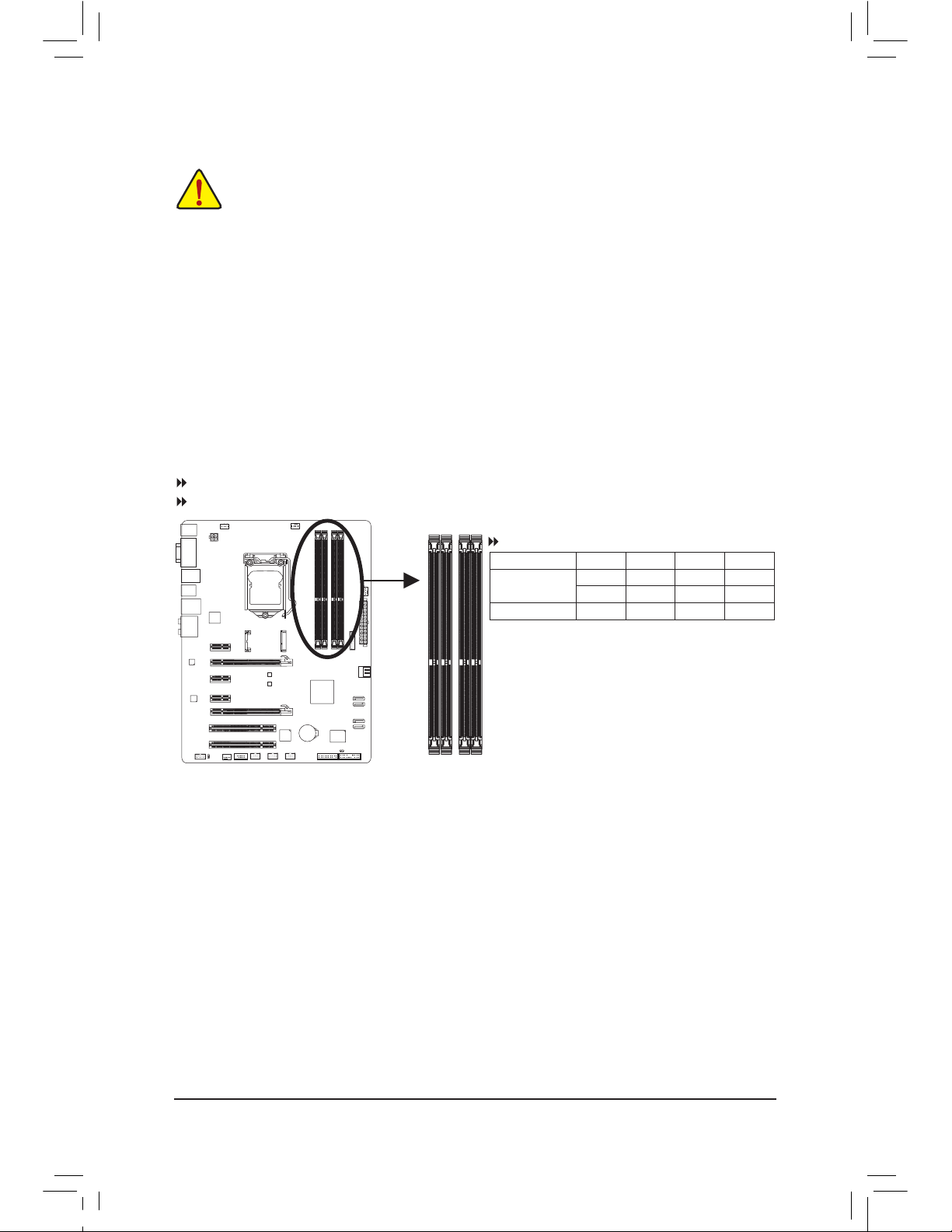
Dual Channel Memory Congurations Table
(SS=Single-Sided, DS=Double-Sided, "- -"=No Memory)
1-4-1 Dual Channel Memory Conguration
This motherboard provides four DDR3 memory sockets and supports Dual Channel Technology. After the
memory is installed, the BIOS will automatically detect the specications and capacity of the memory. Enabling Dual Channel memory mode will double the original memory bandwidth.
The four DDR3 memory sockets are divided into two channels and each channel has two memory sockets as
following:
Channel A: DDR3_4, DDR3_2
Channel B: DDR3_3, DDR3_1
DDR3_4
DDR3_2
DDR3_3
DDR3_1
Due to CPU limitations, read the following guidelines before installing the memory in Dual Channel mode.
Dual Channel mode cannot be enabled if only one DDR3 memory module is installed.1.
When enabling Dual Channel mode with two or four memory modules, it is recommended that 2.
memory of the same capacity, brand, speed, and chips be used and installed in the same colored
DDR3 sockets. For optimum performance, when enabling Dual Channel mode with two memory
modules, we recommend that you install them in the DDR3_1 and DDR3_2 sockets.
DDR3_4 DDR3_2 DDR3_3 DDR3_1
Tw
o Modules - - DS/SS - - DS/SS
DS/SS - - DS/SS - -
Four Modules DS/SS DS/SS DS/SS DS/SS
Page 17
- 17 - Hardware Installation
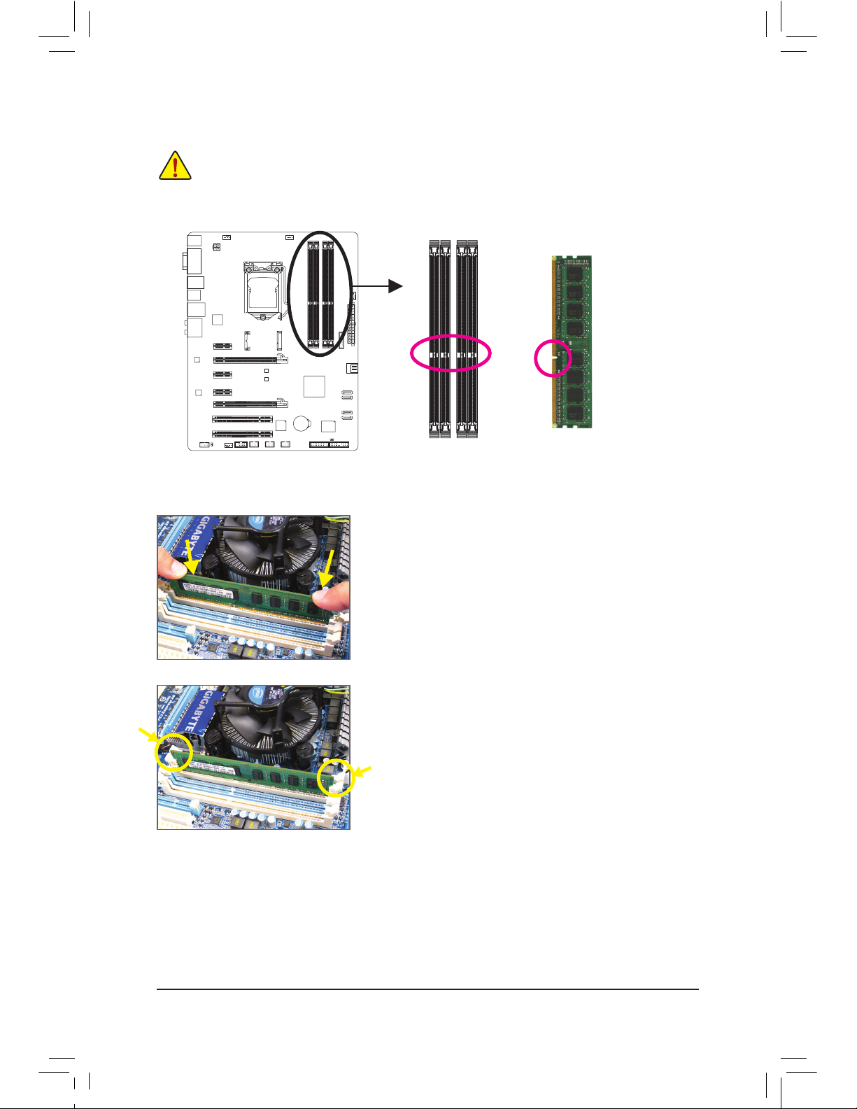
1-4-2 Installing a Memory
Before installing a memory module, make sure to turn off the computer and unplug the power
cord from the power outlet to prevent damage to the memory module. DDR3 and DDR2 DIMMs
are not compatible to each other or DDR DIMMs. Be sure to install DDR3 DIMMs on this motherboard.
Notch
DDR3 DIMM
A DDR3 memory module has a notch, so it can only t in one direction. Follow the steps below to correctly
install your memory modules in the memory sockets.
Step 1:
Note
the orientation of the memory module. Spread the retaining
clips at both ends of the memory socket. Place the memory module
on the socket. As indicated in the picture on the left, place your ngers on the top edge of the memory, push down on the memory and
insert it vertically into the memory socket.
Step 2:
The clips at both ends of the socket will snap into place when the
memory module is securely inserted.
Page 18
- 18 -Hardware Installation
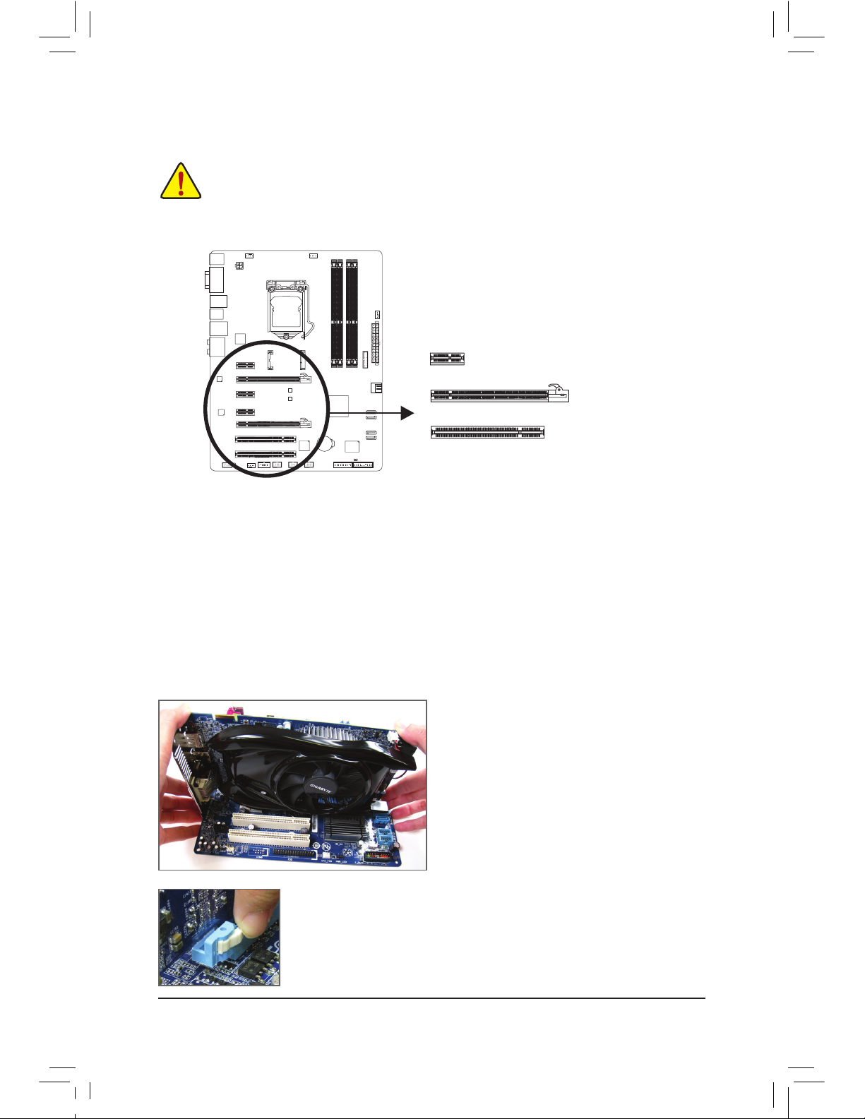
1-5 Installing an Expansion Card
Read the following guidelines before you begin to install an expansion card:
Make sure the motherboard supports the expansion card. Carefully read the manual that came
•
with your expansion card.
Always turn off the computer and unplug the power cord from the power outlet before installing
•
an expansion card to prevent hardware damage.
Follow the steps below to correctly install your expansion card in the expansion slot.
1. Locate
an expansion slot that supports your card. Remove the metal slot cover from the chassis back
panel.
2. Align the card with the slot, and press down on the card until it is fully seated in the slot.
3. Make sure the metal contacts on the card are completely inserted into the slot.
4. Secure the card’s metal bracket to the chassis back panel with a screw.
5. After installing all expansion cards, replace the chassis cover(s).
6. Turn on your computer. If necessary, go to BIOS Setup to make any required BIOS changes for your expansion card(s).
7. Install the driver provided with the expansion card in your operating system.
Example: Installing and Removing a PCI Express Graphics Card:
•InstallingaGraphicsCard:
Gently push down on the top edge of the card until
it is fully inserted into the PCI Express slot. Make
sure the card is securely seated in the slot and
does not rock.
•RemovingtheCard:
Press the latch at the end of the PCI Express slot to release the card and then
pull the card straight up from the slot.
PCI Express x1 Slot
PCI Express x16 Slot
PCI Slot
Page 19
- 19 - Hardware Installation
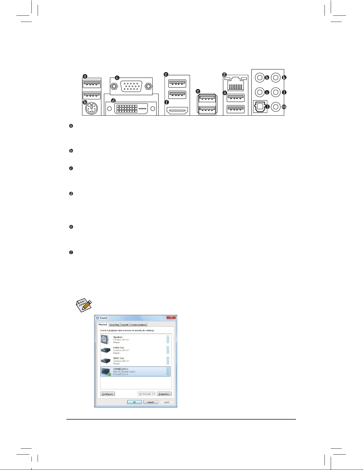
1-6 Back Panel Connectors
USB 2.0/1.1 Port
The USB port supports the USB 2.0/1.1 specication. Use this port for USB devices such as a USB keyboard/mouse, USB printer, USB ash drive and etc.
PS/2 Keyboard/Mouse Port
Use this port to connect a PS/2 mouse or keyboard.
D-Sub Port
The D-Sub port supports a 15-pin D-Sub connector. Connect a monitor that supports D-Sub connection
to this port.
DVI-D Port
(Note)
The DVI-D port conforms to the DVI-D specicationand supports a maximum resolution of 1920x1200 (the
actual resolutions supported depend on the monitor being used). Connect a monitor that supports DVI-D
connection to this port.
USB 3.0/2.0 Port
The USB 3.0 port supports the USB 3.0 specication and is compatible to the USB 2.0/1.1 specication.
Use this port for USB devices such as a USB keyboard/mouse, USB printer, USB ash drive and etc.
HDMI Port
HDMI (High-Denition Multimedia Interface) is an all-digital audio/video interface capable of transmitting uncompressed audio/video signals. The HDMI port is HDCP compliant and supports Dolby TrueHD
and DTS HD Master Audio formats. It also supports up to 192KHz/24bit 8-channel LPCM audio output.
You can use this port to connect your HDMI-supported monitor. The maximum supported resolution is
1920x1200, but the actual resolutions supported are dependent on the monitor being used.
In Windows 7, select Start>Control Panel>Hardware
and Sound>Sound>Playback, set Intel(R) Display Audio
to the default playback device.
(Note) The DVI-D port does not support D-Sub connection by adapter.
After installing the HDMI device, make sure to set the default sound playback device to HDMI.
(The item name may differ depending on your operating system. The screenshot below is from Windows 7.)
Page 20
- 20 -Hardware Installation
Center/Subwoofer Speaker Out Jack (Orange)
Use this audio jack to connect center/subwoofer speakers in a 5.1/7.1-channel audio conguration.
Rear Speaker Out Jack (Black)
This jack can be used to connect front speakers in a 4/5.1/7.1-channel audio conguration.
Optical S/PDIF Out Connector
This connector provides digital audio out to an external audio system that supports digital optical audio.
Before using this feature, ensure that your audio system provides an optical digital audio in connector.
Line In Jack (Blue)
The default line in jack. Use this audio jack for line in devices such as an optical drive, walkman, etc.
Line Out Jack (Green)
The default line out jack. Use this audio jack for a headphone or 2-channel speaker. This jack can be
used to connect front speakers in a 4/5.1/7.1-channel audio conguration.
Mic In Jack (Pink)
The default Mic in jack. Microphones must be connected to this jack.
When r
emoving the cable connected to a back panel connector, rst remove the cable from
•
your device and then remove it from the motherboard.
When removing the cable, pull it straight out from the connector. Do not rock it side to side to
•
prevent an electrical short inside the cable connector.
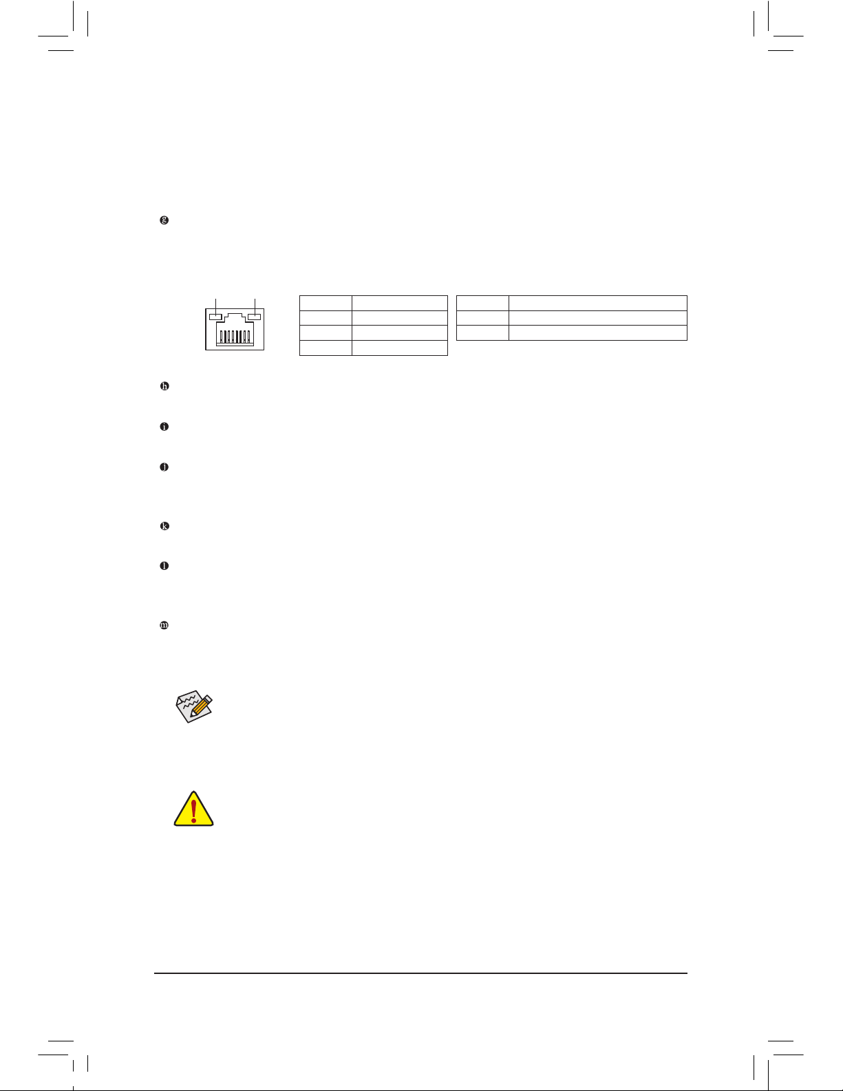
Activity LED
Connection/
Speed LED
LAN Port
Activity LED:Connection/Speed LED:
State Description
Orange 1 Gbps data rate
Green 100 Mbps data rate
Off 10 Mbps data rate
State Description
Blinking Data transmission or receiving is occurring
Off No data transmission or receiving is occurring
RJ-45 LAN Port
The Gigabit Ethernet LAN port provides Internet connection at up to 1 Gbps data rate. The following
describes the states of the LAN port LEDs.
The audio jacks can be recongured to perform different functions via the audio software.
If you
install a Side Speaker, you need to retask other audio jack to be Side Speaker out.
Only microphones still MUST be connected to the default Mic in jack. Refer to the instructions on setting up
a 2/4/5.1/7.1-channel audio conguration in Chapter 5, "Conguring 2/4/5.1/7.1-Channel Audio."
Dual Display Congurations for the Onboard Graphics:
This motherboard provides three video output ports: D-Sub, DVI-D, and HDMI. Dual monitor confgurations are supported in operating system environment only, but not during the BIOS Setup or POST process.
Page 21
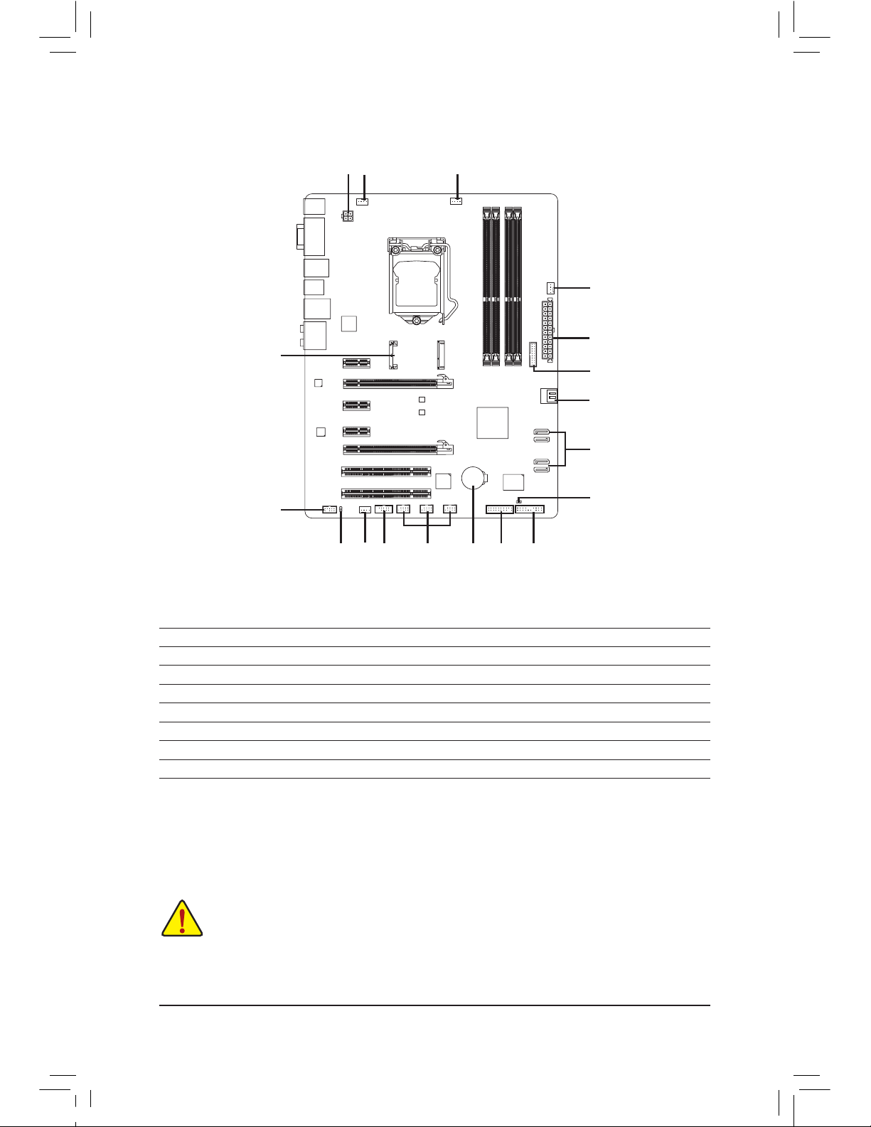
- 21 - Hardware Installation
1-7 Internal Connectors
Read the following guidelines before connecting external devices:
First make sure your devices are compliant with the connectors you wish to connect.
•
Before installing the devices, be sure to turn off the devices and your computer. Unplug the
•
power cord from the power outlet to prevent damage to the devices.
After installing the device and before turning on the computer, make sure the device cable has
•
been securely attached to the connector on the motherboard.
14
1
2
4
4
1315
8
6
12
9
16
3
5
7
4
11
1) ATX_12V
2) AT
X
3) CPU_FA
N
4) SYS_FA
N1/2/3
5) BAT
6) SATA
3 0/1
7) SATA
2 2/3/4/5
8) mSATA
9) CLR_CMOS
10) F_PA
NEL
11
) F_AUDIO
12) SPDIF_O
13) F_USB1/F_USB2/F_USB3
14) F_USB30
15) COMA
16) TPM
10
Page 22
- 22 -Hardware Installation
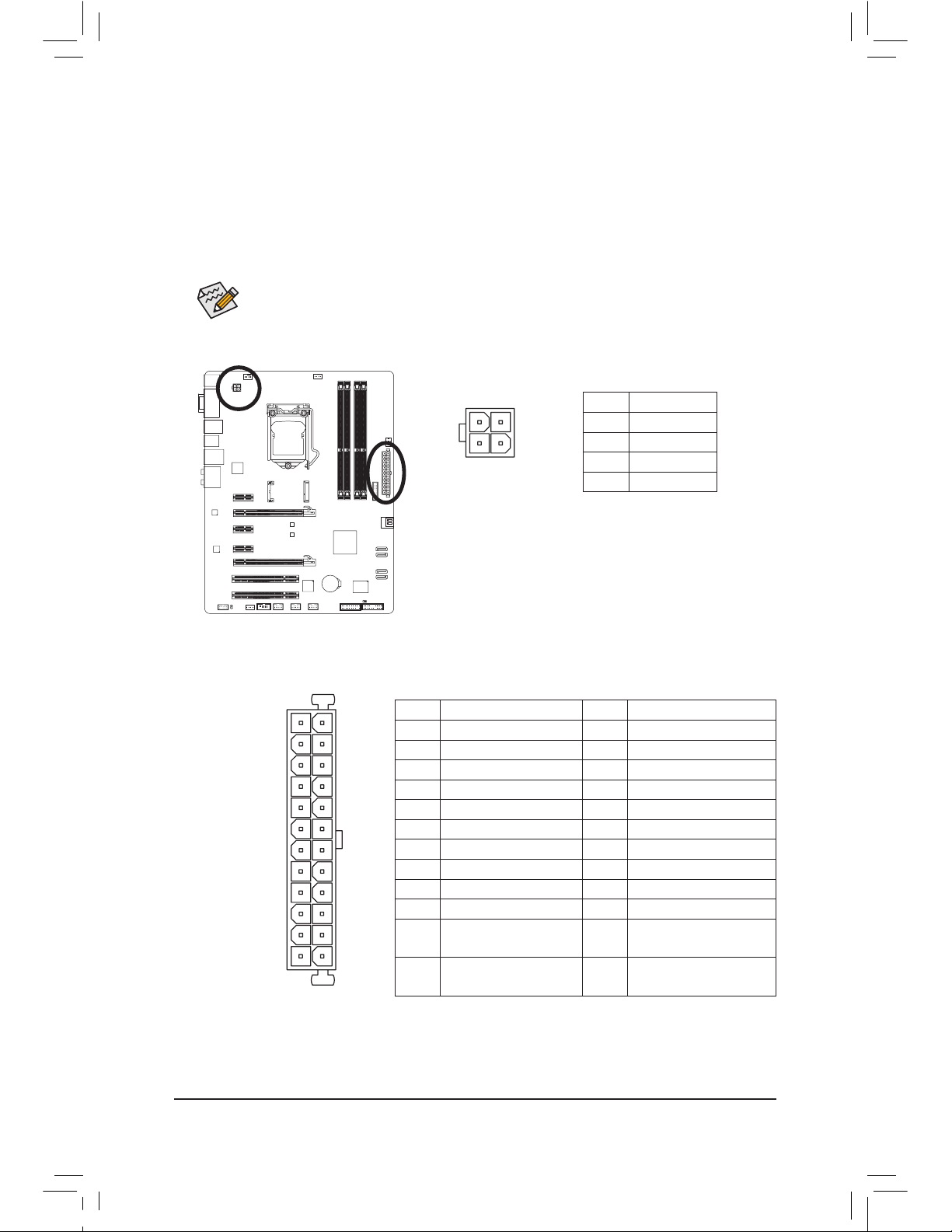
1/2) ATX_12V/ATX (2x2 12V Power Connector and 2x12 Main Power Connector)
With the use of the power connector, the power supply can supply enough stable power to all the components on the motherboard. Before connecting the power connector, rst make sure the power supply
is turned off and all devices are properly installed. The power connector possesses a foolproof design.
Connect the power supply cable to the power connector in the correct orientation.
The 12V power connector mainly supplies power to the CPU. If the 12V power connector is not connected, the computer will not start.
To
meet expansion requirements, it is recommended that a power supply that can withstand high
power consumption be used (500W or greater). If a power supply is used that does not provide
the required power, the result can lead to an unstable or unbootable system.
131
2412
AT
X
ATX:
Pin No. Denition Pin No. Denition
1 3.3V 13 3.3V
2 3.3V 14 -12V
3 GND 15 GND
4 +5V 16 PS_ON (soft On/Off
)
5 GND 17 GND
6 +5V 18 GND
7 GND 19 GND
8 Power Good 20 -5V
9 5VSB (stand by +5V) 21 +5V
10 +12V 22 +5V
11 +12V (Only for 2x12-pin
ATX)
23 +5V (Only for 2x12-pin ATX)
12 3.3V (Onl y for 2x12-pi n
ATX)
24 G ND (Onl y for 2x12-p in
ATX)
ATX_12V:
Pin No. Denition
1 GND
2 GND
3 +12V
4 +12V
ATX_12V
2
1
4
3
Page 23
- 23 - Hardware Installation
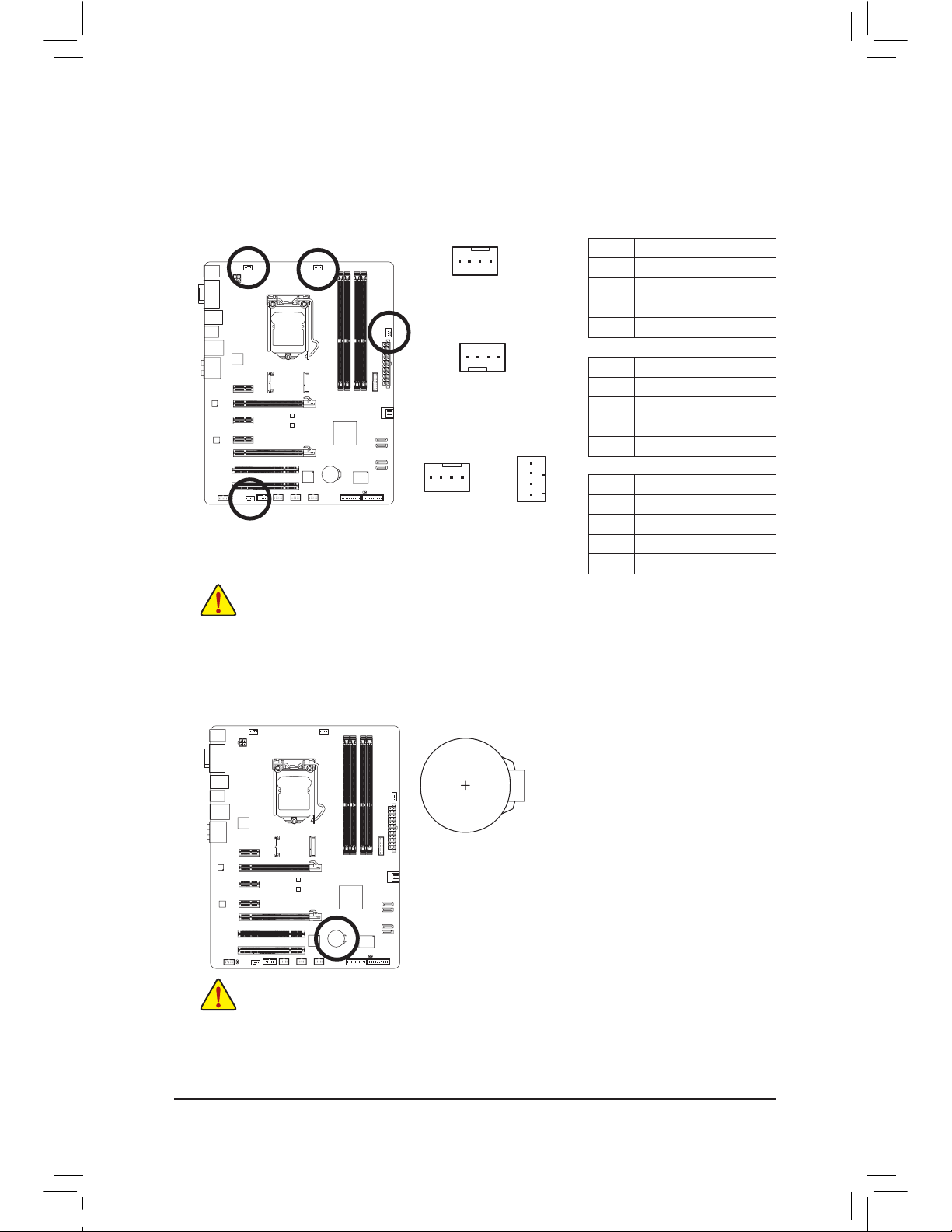
Be sure to connect fan cables to the fan headers to prevent your CPU and system from over-
•
heating. Overheating may result in damage to the CPU or the system may hang.
These fan headers are not conguration jumper blocks. Do not place a jumper cap on the
•
headers.
3/4) CPU_FAN/SYS_FAN1/SYS_FAN2/SYS_FAN3 (Fan Headers)
All fan headers on this motherboard are 4-pin. Most fan headers possess a foolproof insertion design.
When connecting a fan cable, be sure to connect it in the correct orientation (the black connector wire is
the ground wire). The speed control function requires the use of a fan with fan speed control design. For
optimum heat dissipation, it is recommended that a system fan be installed inside the chassis.
CPU_FAN:
Pin No. Denition
1 GND
2 +12V /Speed Control
3 Sense
4 Speed Control
SYS_FAN1:
Pin No. Denition
1 GND
2 +12V /Speed Control
3 Sense
4 Reserve
CPU_FAN
SYS_FAN1
DEBUG
PORT
1
1
5) BAT (Battery)
The battery provides power to keep the values (such as BIOS congurations, date, and time information)
in t
he CMOS when the computer is turned off. Replace the battery when the battery voltage drops to a
low level, or the CMOS values may not be accurate or may be lost.
You may clear the CMOS values by removing the battery:
1. Tu
rn off your computer and unplug the power cord.
2. Gently
remove the battery from the battery holder and wait for one
minute. (
Or use a metal object like a screwdriver to touch the positive
and n
egative terminals of the battery holder, making them short for 5
seconds.)
3. R
eplace the battery.
4. P
lug in the power cord and restart your computer.
Always turn off
your computer and unplug the power cord before replacing the battery.
•
Replace t
he battery with an equivalent one. Danger of explosion if the battery is replaced with an incorrect
•
model.
Contact t
he place of purchase or local dealer if you are not able to replace the battery by yourself or uncer-
•
tain about the battery model.
When i
nstalling the battery, note the orientation of the positive side (+) and the negative side (-) of the bat-
•
tery (the positive side should face up).
Used batteries must be handled in accordance with local environmental regulations.
•
SYS_FAN2
DEBUG
PORT
1
SYS_FAN3
DEBUG
PORT
1
SYS_FAN 2/3:
Pin No. Denition
1 GND
2 +12V
3 Sense
4 Speed Control
Page 24
- 24 -Hardware Installation
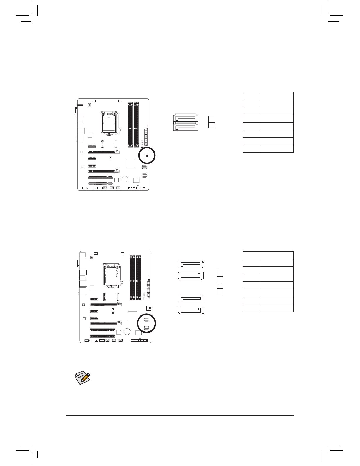
7) SATA2 2/3/4/5 (SATA 3Gb/s Connectors, Controlled by Intel Z77/H77 Chipset)
The SATA connectors conform to SATA 3Gb/s standard and are compatible with SATA 1.5Gb/s standard.
Each SATA connector supports a single SATA device.
(Please use the included SATA 3Gb/s cable)
. The
Intel Z77/H77 Chipset supports RAID 0, RAID 1, RAID 5, and RAID 10. Refer to Chapter 5, "Conguring
SATA Hard Drive(s)," for instructions on conguring a RAID array.
6) SATA3 0/1 (SATA 6Gb/s Connectors, Controlled by Intel Z77/H77 Chipset)
The SATA connectors conform to SATA 6Gb/s standard and are compatible with SATA 3Gb/s and SATA
1.5Gb/s standard. Each SATA connector supports a single SATA device. (Please use the included SATA
6Gb/s cable).
The SATA3 0/1 connectors support RAID 0 and RAID 1. RAID 5 and RAID 10 can be im-
plemented on the two connectors with the "SATA2 2/3/4/5" and mSATA connectors
(Note)
. Refer to Chapter
5, "Conguring SATA Hard Drive(s)," for instructions on conguring a RAID array.
A RAID
0 or RAID 1 conguration requires at least two hard drives. If more than two hard
•
drives are to be used, the total number of hard drives must be an even number.
A RAID 5 conguration requires at least three hard drives. (The total number of hard drives
•
does not have to be an even number.)
A RAID 10 conguration requires four hard drives.
•
(Note) When a RAID set is built across the SATA 6Gb/s and SATA 3Gb/s channels, the system perfor-
mance of the RAID set may vary depending on the devices being connected.
1
1
G.QBOFM
SATA3
7
7
Pin No. Denition
1 GND
2 TXP
3 TXN
4 GND
5 RXN
6 RXP
7 GND
Pin No. Denition
1 GND
2 TXP
3 TXN
4 GND
5 RXN
6 RXP
7 GND
1
0
SATA
2
7
7
1
1
DEBUG
PORT
G.QBOFM
DEBUG
PORT
G.QBOFM
7
1
7
1
2
3
4
5
Page 25
- 25 - Hardware Installation
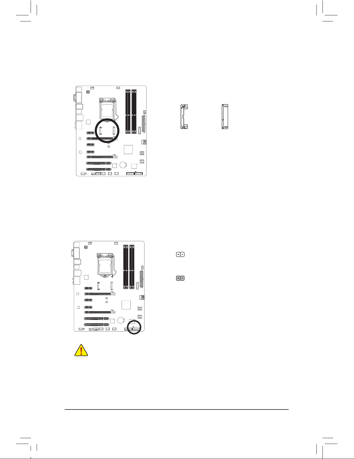
8) mSATA (Solid-State Drive Connector, Controlled by the Intel Z77/H77 Chipset)
The mSATA connector conforms to SATA 3Gb/s standard and can connect to a single solid-state drive.
When the mSATA connector is installed with a solid-state drive, the SATA2 5 connector will become unavailable.
mSATA
(H61M-D2)
9) CLR_CMOS (Clear CMOS Jumper)
Use this jumper to clear the CMOS values (e.g. date information and BIOS congurations) and reset the
CMOS values to factory defaults. To clear the CMOS values, use a metal object like a screwdriver to
touch the two pins for a few seconds.
Always turn off your computer and unplug the power cord from the power outlet before clear-
•
ing the CMOS values.
After system restart, go to BIOS Setup to load factory defaults (select Load Optimized De-
•
faults) or manually congure the BIOS settings (refer to Chapter 2, "BIOS Setup," for BIOS
congurations).
Open: Normal
Short: Clear CMOS Va
lues
Page 26
- 26 -Hardware Installation
The front panel design may differ by chassis. A front panel module mainly consists of power
switch, reset switch, power LED, hard drive activity LED, speaker and etc. When connecting your
chassis front panel module to this header, make sure the wire assignments and the pin assignments are matched correctly.
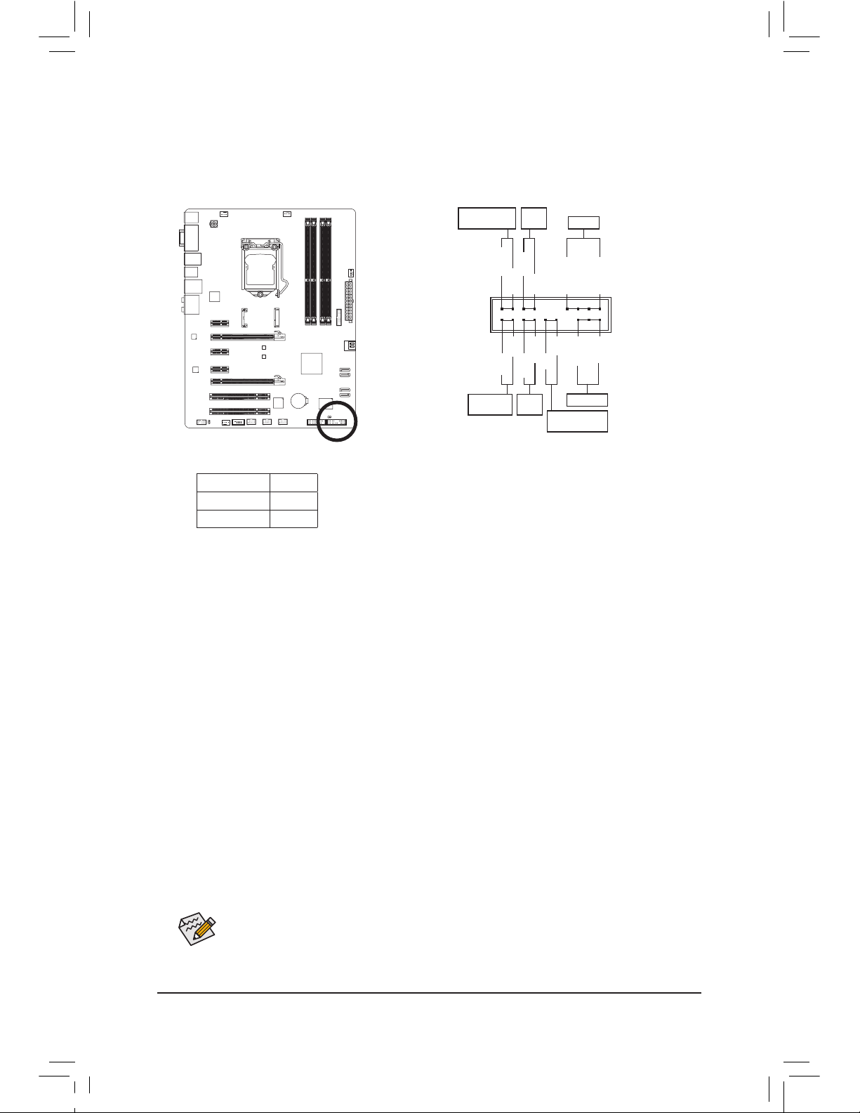
10) F_PANEL (Front Panel Header)
Connect the power switch, reset switch, speaker, chassis intrusion switch/sensor and system status
indicator on the chassis to this header according to the pin assignments below. Note the positive and
negative pins before connecting the cables.
• PW (Power Switch, Red):
C
onnects to the power switch on the chassis front panel. You may congure the way to turn off your
system using the power switch (refer to Chapter 2, "BIOS Setup," "Power Management," for more
information).
• SPEAK (Speaker, Orange):
C
onnects to the speaker on the chassis front panel. The system reports system startup status by issuing a beep code. One single short beep will be heard if no problem is detected at system startup.
• HD (Hard Drive Activity LED, Blue):
C
onnects to the hard drive activity LED on the chassis front panel. The LED is on when the hard drive
is reading or writing data.
• RES (Reset Switch, Green):
C
onnects to the reset switch on the chassis front panel. Press the reset switch to restart the computer
if the computer freezes and fails to perform a normal restart.
• CI (Chassis Intrusion Header, Gray):
C
onnects to the chassis intrusion switch/sensor on the chassis that can detect if the chassis cover
has been removed. This function requires a chassis with a chassis intrusion switch/sensor.
• MSG/PWR (Message/Power/Sleep LED, Yellow/Purple):
C
onnects to the power status indicator on the chassis front panel. The LED
is on when the system is operating. The LED is off when the system is in
S3/S4 sleep state or powered off (S5).
System Status LED
S0 On
S3/S4/S5 Off
Power LED
1
2
19
20
CI-
CI+
PWR-
PWR+
MSG-
PW-
SPEAK+
SPEAK-
MSG+
PW+
Message/Power/
Sleep LED
Speaker
Power
Switch
HD-
RES+
HD+
RES-
Hard Drive
Activity LED
Reset
Switch
Ch
assis Intrusion
Header
Page 27
- 27 - Hardware Installation
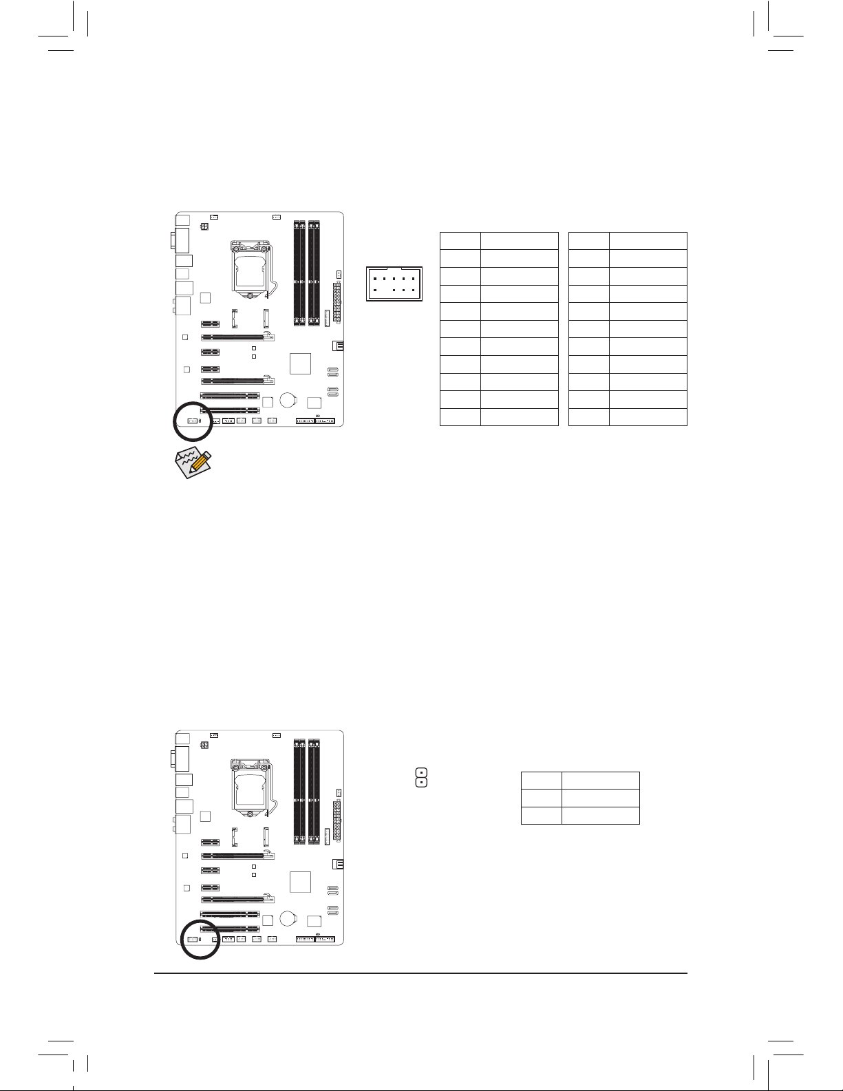
11) F_AUDIO (Front Panel Audio Header)
The front panel audio header supports Intel High Denition audio (HD) and AC'97 audio. You may connect your chassis front panel audio module to this header. Make sure the wire assignments of the module connector match the pin assignments of the motherboard header. Incorrect connection between the
module connector and the motherboard header will make the device unable to work or even damage it.
The f
ront panel audio header supports HD audio by default. If your chassis provides an AC'97
•
front panel audio module, refer to the instructions on how to activate AC'97 functionality via
the audio software in Chapter 5, "Conguring 2/4/5.1/7.1-Channel Audio."
Audio signals will be present on both of the front and back panel audio connections simultane-
•
ously. If you want to mute the back panel audio (only supported when using an HD front panel
audio module), refer to Chapter 5, "Conguring 2/4/5.1/7.1-Channel Audio."
Some chassis provide a front panel audio module that has separated connectors on each wire
•
instead of a single plug. For information about connecting the front panel audio module that
has different wire assignments, please contact the chassis manufacturer.
For HD Front Panel Audio:
For AC'97 Front Panel Audio:
Pin No. Denition
1 MIC2_L
2 GND
3 MIC2_R
4 -ACZ_DET
5 LINE2_R
6 GND
7 FA
UDIO_JD
8 No Pin
9 LINE2_L
10 GND
Pin No. Denition
1 MIC
2 GND
3 MIC Power
4 NC
5 Line Out (R)
6 NC
7 NC
8 No Pin
9 Line Out (L)
10 NC
F_PANEL(NH) F_PANEL
(H61M-D2)
9 1
10 2
1
12) SPDIF_O (S/PDIF Out Header)
This header supports digital S/PDIF Out and connects a S/PDIF digital audio cable (provided by expansion cards) for digital audio output from your motherboard to certain expansion cards like graphics cards
and sound cards. For example, some graphics cards may require you to use a S/PDIF digital audio cable
for digital audio output from your motherboard to your graphics card if you wish to connect an HDMI display to the graphics card and have digital audio output from the HDMI display at the same time.
For information about connecting the S/PDIF digital audio cable, carefully read the manual for your expansion card.
Pin No. Denition
1 SPDIFO
2 GND
Page 28
- 28 -Hardware Installation
13) F_USB1/F_USB2/F_USB3 (USB 2.0/1.1 Headers)
The headers conform to USB 2.0/1.1 specication. Each USB header can provide two USB ports via an
optional USB bracket. For purchasing the optional USB bracket, please contact the local dealer.
G.QBOFM
10
9
2
1
Pin No. Denition
1 Power (5V)
2 Power (5V)
3 USB DX-
4 USB DY-
5 USB DX+
6 USB DY+
7 GND
8 GND
9 No Pin
10 NC
Do not plug the IEEE 1394 bracket (2x5-pin) cable into the USB 2.0/1.1 header.
•
Prior to installing the USB bracket, be sure to turn off your computer and unplug the power
•
cord from the power outlet to prevent damage to the USB bracket.
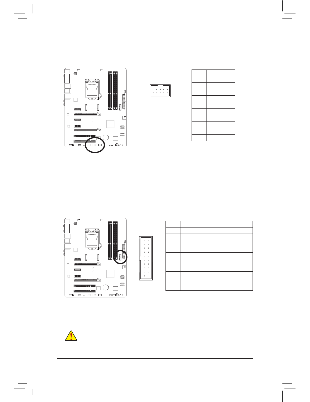
14) F_USB30 (USB 3.0/2.0 Header)
The header conforms to USB 3.0/2.0 specication and can provide two USB ports. For purchasing the
optional 3.5" front panel that provides two USB 3.0/2.0 ports, please contact the local dealer.
F_AUDIO(H)
DB_PORT
F_PANEL(NH) F_PANEL
(H61M-D2)
10
11
20
1
Pin No. Denition Pin No. Denition
1 VBUS 11 D2+
2 SSRX1- 12 D2-
3 SSRX1+ 13 GND
4 GND 14 SSTX2+
5 SSTX1- 15 SSTX2-
6 SSTX1+ 16 GND
7 GND 17 SSRX2+
8 D1- 18 SSRX2-
9 D1+ 19 VBUS
10 NC 20 No Pin
Page 29
- 29 - Hardware Installation
20
19
2
1
F_AUDIO(H)
DB_PORT
F_PANEL(NH) F_PANEL
(H61M-D2)
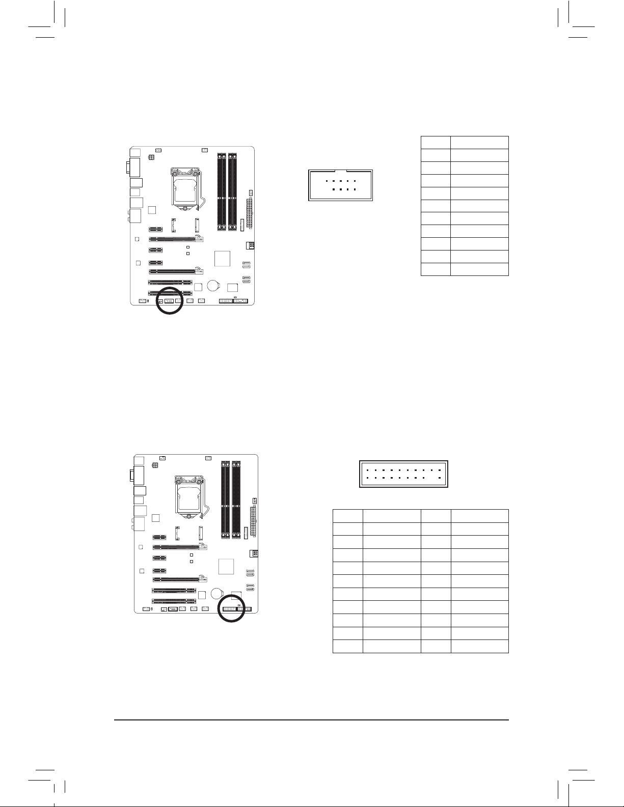
16) TPM (Trusted Platform Module Header)
You may connect a TPM (Trusted Platform Module) to this header.
Pin No. Denition Pin No. Denition
1 LCLK 11 LAD0
2 GND 12 GND
3 LFRAME 13 NC
4 No Pin 14 ID
5 LRESET 15 SB3V
6 NC 16 SERIRQ
7 LAD3 17 GND
8 LAD2 18 NC
9 VCC3 19 NC
10 LAD1 20 SUSCLK
10
9
2
1
15) COMA (Serial Port Header)
The COM header can provide one serial port via an optional COM port cable. For purchasing the optional COM port cable, please contact the local dealer.
Pin No. Denition
1 NDCD-
2 NSIN
3 NSOUT
4 NDTR-
5 GND
6 NDSR-
7 NRT
S-
8 NCTS-
9 NRI-
10 No Pin
Page 30

- 30 -Hardware Installation
Page 31

- 31 - BIOS Setup
BIOS (Basic Input and Output System) records hardware parameters of the system in the CMOS on the
motherboard. Its major functions include conducting the Power-On Self-Test (POST) during system startup,
saving system parameters and loading operating system, etc. BIOS includes a BIOS Setup program that allows
the user to modify basic system conguration settings or to activate certain system features.
When the power is turned off, the battery on the motherboard supplies the necessary power to the CMOS to
keep the conguration values in the CMOS.
To access the BIOS Setup program, press the <Delete> key during the POST when the power is turned on.
To upgrade the BIOS, use either the GIGABYTE Q-Flash or @BIOS utility.
Q-Flash allows the user to quickly and easily upgrade or back up BIOS without entering the operating •
system.
@BIOS is a Windows-based utility that searches and downloads the latest version of BIOS from the •
Internet and updates the BIOS.
For instructions on using the Q-Flash and @BIOS utilities, refer to Chapter 4, "BIOS Update Utilities."
Chapter 2 BIOS Setup
Because BIOS ashing is potentially risky, if you do not encounter problems using the current •
version of BIOS, it is recommended that you not ash the BIOS. To ash the BIOS, do it with
caution. Inadequate BIOS ashing may result in system malfunction.
It is recommended that you not alter the default settings (unless you need to) to prevent system •
instability or other unexpected results. Inadequately altering the settings may result in system's
failure to boot. If this occurs, try to clear the CMOS values and reset the board to default values.
(Refer to the "Load Optimized Defaults" section in this chapter or introductions of the battery/
clear CMOS jumper in Chapter 1 for how to clear the CMOS values.)
Page 32

BIOS Setup - 32 -
2-1 Startup Screen
The following startup Logo screen will appear when the computer boots.
Function
Keys:
<DEL>: BIOS SETUP\Q-FLASH
Press the <Delete> key to enter BIOS Setup or to access the Q-Flash utility in BIOS Setup.
<F9>: SYSTEM INFORMATION
Press
the <F9> key to display your system information.
<F12>: BOOT MENU
Boot Menu allows you to set the rst boot device without entering BIOS Setup. In Boot Menu, use the up
arrow key <h> or the down arrow key <i> to select the rst boot device, then press <Enter> to accept.
The system will boot from the device immediately.
Note: The setting in Boot Menu is effective for one time only. After system restart, the device boot order
will
still be based on BIOS Setup settings.
<END>: Q-FLASH
Press the <End> key to access the Q-Flash utility directly without having to enter BIOS Setup rst.
Function Keys
Page 33

- 33 - BIOS Setup
2-2 The Main Menu
A. The 3D BIOS Screen (Default)
On GIGABYTE's uniquely designed 3D BIOS screen, you can use your mouse to move through the motherboard
image and click to enter the function menu in each area for quick conguration. For example, pass your mouse
arrow over the CPU and memory sockets and enter the System Tuning menu to congure CPU/memory
frequency, memory timings, and voltage settings. For more detailed conguration items, you can click the
function menu icons at the bottom of the screen or press <F1> to switch to the main menu of the BIOS Setup
program. (If a mouse is not connected, the 3D BIOS screen will automatically switch to the main menu of the
BIOS Setup Program.)
B. The Main Menu of the BIOS Setup Program
On the main menu of the BIOS Setup program, press arrow keys to move among the items and press <Enter>
to
accept or enter a sub-menu. Or you can use your mouse to select the item you want.
(Sample BIOS Version: F3c)
Setup Menus
Function Keys
Help
Enter Q-Flash
Select Default
Language
Conguration Items
Current Settings
Switch to 3D
BIOS Screen
Page 34

BIOS Setup - 34 -
BIOS Setup Menus
M.I.T.
Use this menu to congure the clock, frequency, and voltages of your CPU and memory, etc. Or check
the system/CPU temperatures, voltages, and fan speeds.
System
Use this menu to congure the default language used by the BIOS and system time and date. This menu
also displays information on the devices connected to the SATA ports.
BIOS Features
Use this menu to congure the device boot order, advanced features available on the CPU, and the
primary display adapter.
Peripherals
Use this menu to congure all peripheral devices, such as SATA, USB, integrated audio, and integrated
LAN, etc.
Power Management
Use this menu to congure all the power-saving functions.
Save & Exit
Save all the changes made in the BIOS Setup program to the CMOS and exit BIOS Setup. You can
save the current BIOS settings to a prole or load optimized defaults for optimal-performance system
operations.
If
the system is not stable as usual, load optimized defaults to set your system to its defaults. •
The BIOS Setup menus described in this chapter are for reference only and may differ by BIOS •
version.
BIOS Setup Program Function Keys
<f><g>
Mov
e the selection bar to select a setup menu
<h><i>
Mov
e the selection bar to select an conguration item on a menu
<Enter> Execute
command or enter a menu
<+>/<Page
Up> Increase the numeric value or make changes
<->/<Page
Down> Decrease the numeric value or make changes
<F5> Restore
the previous BIOS settings for the current submenus
<F7> Load
the Optimized BIOS default settings for the current submenus
<F8> Access
the Q-Flash utility
<F9> Display
system information
<F10> Sav
e all the changes and exit the BIOS Setup program
<F12> Capture
the current screen as an image and save it to your USB drive
<Esc> Main
Menu: Exit the BIOS Setup programSubmenus: Exit current submenu
Page 35

- 35 - BIOS Setup
2-3 M.I.T.
Whether the system will work stably with the overclock/overvoltage settings you made is dependent
on your overall system congurations. Incorrectly doing overclock/overvoltage may result in damage
to CPU, chipset, or memory and reduce the useful life of these components. This page is for advanced
users only and we recommend you not to alter the default settings to prevent system instability or
other unexpected results. (Inadequately altering the settings may result in system's failure to boot.
If this occurs, clear the CMOS values and reset the board to default values.)
This section provides information on the BIOS version, CPU base clock, CPU frequency, memory frequency,
total memory size , CPU temperature, Vcore, and memory voltage.
Page 36

BIOS Setup - 36 -
M.I.T. Current Status `
This screen provides information on CPU/memory frequencies/parameters.
Advanced Frequency Settings `
CPU/PCIe Base Clock &
Allows you to manually set the CPU base clock and PCIe bus frequency in 0.01 MHz increments.
(Default: Auto)
Important: It is highly recommended that the CPU frequency be set in accordance with the CPU
specications.
Internal Graphics Clock &
Allows you to set the onboard graphics clock. The adjustable range is from 400 MHz to 3200 MHz.
(Default: Auto)
CPU Clock Ratio &
Allows you to alter the clock ratio for the installed CPU. The adjustable range is dependent on the CPU
being installed.
CPU Frequency &
Displays the current operating CPU frequency.
Page 37

- 37 - BIOS Setup
(Note) This item is present only when you install a CPU that supports this feature. For more information
about Intel CPUs' unique features, please visit Intel's website.
CPU Clock Ratio, CPU Frequency &
The settings under the two items above are synchronous to those under the same items on the Advanced
Frequency Settings menu.
Real-Time CPU Ratio Control in OS &
(Note)
Enabled allows you to make real-time changes to the CPU clock ratio in your operating system. (Default:
Disabled)
Intel(R) Turbo Boost Technology &
(Note)
Allows you to determine whether to enable the Intel CPU Turbo Boost technology. Auto lets the BIOS
automatically congure this setting. (Default: Auto)
Turbo Ratio (1-Core Active~4-Core Active) &
(Note)
Allows you to set the CPU Turbo ratios for different number of active cores. Auto sets the CPU Turbo
ratios according to the CPU specications. (Default: Auto)
Turbo Power Limit (Watts) &
Allows you to set a power limit for CPU Turbo mode. When the CPU power consumption exceeds the
specied power limit, the CPU will automatically reduce the core frequency in order to reduce the power.
Auto sets the current limit according to the CPU specications. (Default: Auto)
Core Current Limit (Amps) &
Allows you to set a current limit for CPU Turbo mode. When the CPU current exceeds the specied
current limit, the CPU will automatically reduce the core frequency in order to reduce the current. Auto
sets the current limit according to the CPU specications. (Default: Auto)
CPU Core Enabled &
(Note)
Allows you to determine whether to enable all CPU cores. Auto lets the BIOS automatically congure
this setting. (Default: Auto)
Advanced CPU Core Features `
Page 38

BIOS Setup - 38 -
Hyper-Threading Technology &
(Note 1)
Allows you to determine whether to enable multi-threading technology when using an Intel CPU that
supports this function. This feature only works for operating systems that support multi-processor mode.
Auto lets the BIOS automatically congure this setting. (Default: Auto)
CPU Enhanced Halt (C1E) &
(Note 1)
Enables or disables Intel CPU Enhanced Halt (C1E) function, a CPU power-saving function in system halt
state. When enabled, the CPU core frequency and voltage will be reduced during system halt state to
decrease power consumption. Auto lets the BIOS automatically congure this setting. (Default: Auto)
C3/C6 State Support &
(Note 1)
Allows you to determine whether to let the CPU enter C3/C6 mode in system halt state. When enabled, the
CPU core frequency and voltage will be reduced during system halt state to decrease power consumption.
The C3/C6 state is a more enhanced power-saving state than C1. Auto lets the BIOS automatically
congure this setting. (Default: Auto)
CPU Thermal Monitor &
(Note 1)
Enables or disables Intel CPU Thermal Monitor function, a CPU overheating protection function. When
enabled, the CPU core frequency and voltage will be reduced when the CPU is overheated. Auto lets
the BIOS automatically congure this setting. (Default: Auto)
CPU EIST Function &
(Note 1)
Enables or disables Enhanced Intel SpeedStep Technology (EIST). Depending on CPU loading, Intel
EIST technology can dynamically and effectively lower the CPU voltage and core frequency to decrease
average power consumption and heat production. Auto lets the BIOS automatically congure this setting.
(Default: Auto)
Extreme Memory Prole (X.M.P.) &
(Note 2)
Allows the BIOS to read the SPD data on XMP memory module(s) to enhance memory performance
when enabled.
Disabled Disables this function. (Default)
Prole1 Uses Prole 1 settings.
Prole2
(Note 2)
Uses Prole 2 settings.
System Memory Multiplier &
Allows you to set the system memory multiplier. Auto sets memory multiplier according to memory SPD
data. (Default: Auto)
Memory Frequency(Mhz) &
The rst memory frequency value is the normal operating frequency of the memory being used; the second
is the memory frequency that is automatically adjusted according to the System Memory Multiplier
settings.
(Note
1) This item is present only when you install a CPU that supports this feature. For more information
about Intel CPUs' unique features, please visit Intel's website.
(Note 2) This item is present only when you install a CPU and a memory module that support this feature.
Page 39

- 39 - BIOS Setup
Advanced Memory Settings `
(Note) This item is present only when you install a CPU and a memory module that support this feature.
Extreme Memory Prole (X.M.P.) &
(Note)
, System Memory Multiplier (SPD), Memory
Frequency(Mhz)
The settings under the three items above are synchronous to those under the same items on the Advanced
Frequency Settings menu.
Performance Enhance &
Allows the system to operate at three different performance levels.
Normal Lets the system operate at its basic performance level.
Turbo Lets the system operate at its good performance level. (Default)
Extreme Lets the system operate at its best performance level.
DRAM Timing Selectable (SPD) &
Quick and Expert allows the Channel Interleaving, Rank Interleaving, and memory timing settings
below to be congurable. Options are: Auto (default), Quick, Expert.
Prole DDR Voltage &
When using a non-XMP memory module or Extreme Memory Prole (X.M.P.) is set to Disabled, this
item will display as 1.50V. When Extreme Memory Prole (X.M.P.) is set to Prole1 or Prole2, this
item will display the value based on the SPD data on the XMP memory.
Prole VTT Voltage &
The value displayed here is dependent on the CPU being used.
Channel Interleaving &
Enables or disables memory channel interleaving. Enabled allows the system to simultaneously access
different channels of the memory to increase memory performance and stability. Auto lets the BIOS
automatically congure this setting. (Default: Auto)
Rank Interleaving &
Enables or disables memory rank interleaving. Enabled allows the system to simultaneously access
different ranks of the memory to increase memory performance and stability. Auto lets the BIOS
automatically congure this setting. (Default: Auto)
Page 40

BIOS Setup - 40 -
This sub-menu provides memory timing settings for each channel of memory. The respective timing setting
screens are congurable only when DRAM Timing Selectable is set to Quick or Expert. Note: Your system
may become unstable or fail to boot after you make changes on the memory timings. If this occurs, please
reset the board to default values by loading optimized defaults or clearing the CMOS values.
Channel
A/B Timing Settings `
Advanced Voltage Settings `
Page 41

- 41 - BIOS Setup
3D Power Control `
PWM Phase Control &
Allows you to automatically change the PWM phase according to the CPU load. The power-saving levels
are (from lowest to highest
): eXm Perf (Extreme Performance ), High Perf (High Performance),Perf
(Performance), Balanced, Mid PWR (Mid Power), and Lite PWR (Light Power). Auto lets the BIOS
automatically
congure this setting. (Default: Auto).
Vcore Voltage Response &
Allows you to congure the response time for Vcore changes using preset levels.
Auto
Lets the BIOS automatically congure this setting. (Default)
Standard~Fast
Selects Standard or Fastwhich represents different levels of the response time
for Vcore changes.
Vcore Loadline Calibration &
Allows you to set the Load-Line Calibration level for the Vcore. The levels are (from highest to lowest):
Extreme, Turbo, High, Medium, Low, and Standard. Selecting a higher level keeps the Vcore more
consistent with what is set in BIOS under heavy load. Auto lets the BIOS automatically congure this
setting
and sets the voltage following Intel's specications. (Default: Auto)
GFX Voltage Loadline Calibration &
Allows you to set the Load-Line Calibration level for the GFX voltage. The levels are (from highest to
lowest): High, Medium, Low, and Standard. Selecting a higher level keeps the GFX voltage more
consistent with what is set in BIOS under heavy load. Auto lets the BIOS automatically congure this
setting
and sets the voltage following Intel's specications. (Default: Auto)
Vcore Protection &
Allows you to set the voltage limit on the Vcore for over-voltage protection. The adjustable range is from
150.0mV
to 500.0mV. Auto lets the BIOS automatically congure this setting. (Default: Auto)
Page 42

BIOS Setup - 42 -
Vcore Current Protection &
Allows you to set the over-current protection level for the Vcore.
Auto
Lets the BIOS automatically congure this setting. (Default)
Standard~Extreme
Selects Standard, Low, Medium, High, Turbo, or Extreme which represents
different
level of over-current protection for the Vcore.
GFX Current Protection &
Allows you to set the over-current protection level for the GFX voltage.
Auto
Lets the BIOS automatically congure this setting. (Default)
Standard~Extreme
Selects Standard, Low, Medium, High, Turbo, or Extreme which represents
different
level of over-current protection for the GFX voltage.
Vcore PWM Thermal Protection &
Allows you to set the PWM thermal protection threshold for the Vcore area. The adjustable range is from
130.0
o
C to 135.0oC. Auto lets the BIOS automatically congure this setting. (Default: Auto)
CPU Core Voltage Control `
This section provides CPU voltage control options.
DRAM Voltage Control `
This section provides memory voltage control options.
Page 43

- 43 - BIOS Setup
PC Health Status `
Reset Case Open Status &
Disabled Keeps or clears the record of previous chassis intrusion status. (Default)
Enabled Clears the record of previous chassis intrusion status and the Case Opened eld will show
"No" at next boot.
Case Opened &
Displays the detection status of the chassis intrusion detection device attached to the motherboard CI
header. If the system chassis cover is removed, this eld will show "Yes", otherwise it will show "No". To
clear the chassis intrusion status record, set Reset Case Open Status to Enabled, save the settings
to the CMOS, and then restart your system.
Page 44

BIOS Setup - 44 -
CPU Vcore/Dram Voltage/+3.3V/+12V &
Displays the current system voltages.
CPU/System Temperature &
Displays current CPU/system temperature.
CPU/System FAN Speed &
Displays current CPU/system fan speeds.
CPU Warning Temperature &
Sets the warning threshold for CPU temperature. When CPU temperature exceeds the threshold, BIOS will
emit warning sound. Options are: Disabled (default), 60oC/140oF, 70oC/158oF, 80oC/176oF, 90oC/194oF.
CPU/System Fan Fail Warning &
Allows the system to emit warning sound if the CPU fan or system fans are not connected or fail. Check
the fan condition or fan connection when this occurs. (Default: Disabled)
CPU Fan Control Mode &
Species how to control CPU fan speed. This item is congurable only when CPU FAN Speed Control
is enabled.
Auto Lets the BIOS automatically detect the type of CPU fan installed and sets the optimal CPU
fan control mode. (Default)
Voltage Sets Voltage mode for a 3-pin CPU fan.
PWM Sets PWM mode for a 4-pin CPU fan.
Note: The Voltage mode can be set for a 3-pin CPU fan or a 4-pin CPU fan. However, for a 4-pin CPU
fan that is not designed following Intel PWM fan specications, selecting PWM mode may not effectively
reduce the fan speed.
CPU Fan Speed Control &
Allows you to determine whether to enable the CPU fan speed control function and adjust the fan
speed.
Normal Allows the CPU fan to run at different speeds according to the CPU temperature. You can
adjust the fan speed with EasyTune based on your system requirements. (Default)
Silent Allows the CPU fan to run at slow speeds.
Manual Allows you to control the CPU fan speed under the Slope PWM item.
Disabled Allows the CPU fan to run at full speeds.
Slope PWM &
Allows you to control the CPU fan speed. This item is congurable only when CPU Fan Speed Control
is set to Manual. Options are: 0.75 PWM value /oC ~ 2.50 PWM value /oC.
1st/2nd/3rd System Fan Speed Control &
Allows you to determine whether to enable the system fan speed control function and adjust the fan
speed.
Normal Allows the system fans to run at different speeds according to the system temperature. You
can adjust the fan speed with EasyTune based on your system requirements. (Default)
Silent Allows the system fans to run at slow speeds.
Manual Allows you to control the system fans speed under the Slope PWM item.
Disabled Allows the system fans to run at full speeds.
Slope PWM &
Allows you to control the system fan speed. This item is congurable only when 1st/2nd/3rd System
Fan Speed Control is set to Manual. Options are: 0.75 PWM value /oC ~ 2.50 PWM value /oC.
Page 45

- 45 - BIOS Setup
2-4 System
This section provides information on your CPU, memory, motherboard model, and BIOS version. You can
also select the default language used by the BIOS and manually set the system time.
System Language &
Selects the default language used by the BIOS.
System Date &
Sets the system date. The date format is week (read-only), month, date and year. Use <Enter> to switch
between the Month, Date, and Year elds and use the <Page Up> or <Page Down> key to set the desired
value.
System Time &
Sets the system time. The time format is hour, minute, and second. For example, 1 p.m. is 13:0:0. Use
<Enter> to switch between the Hour, Minute, and Second elds and use the <Page Up> or <Page Down>
key to set the desired value.
Access Level &
Displays the current access level depending on the type of password protection used. (If no password
is set, the default will display as Administrator.) The Administrator level allows you to make changes to
all BIOS settings; the User level only allows you to make changes to certain BIOS settings but not all.
ATA Port Information `
This section provides information on the device connected to each SATA port controlled by Intel Z77/
H77
Chipset.You can enable/disable each SATA port or enable/disable the hot plug capability.
Page 46

BIOS Setup - 46 -
2-5 BIOS Features
Boot Option Priorities &
Species the overall boot order from the available devices. For example, you can set hard drive as the
rst priority (Boot Option #1) and DVD ROM drive as the second priority (Boot Option #2). The list only
displays the device with the highest priority for a specic type. For example, only hard drive dened as
the rst priority on the Hard Drive BBS Priorities submenu will be presented here.
Removable storage devices that support GPT format will be prexed with "UEFI:" string on the boot
device list. To boot from an operating system that supports GPT partitioning, select the device prexed
with "UEFI:" string.
Or if you want to install an operating system that supports GPT partitioning such as Windows 7 64-bit,
select the optical drive that contains the Windows 7 64-bit installation disk and is prexed with "UEFI:"
string.
Hard Drive/CD/DVD ROM Drive/Floppy Drive/Network Device BBS Priorities &
Species the boot order for a specic device type, such as hard drives, optical drives, oppy disk drives,
and devices that support Boot from LAN function, etc. Press <Enter> on this item to enter the submenu
that presents the devices of the same type that are connected. This item is present only if at least one
device for this type is installed.
Bootup NumLock State &
Enables or disables Numlock feature on the numeric keypad of the keyboard after the POST. (Default:
Enabled)
Full Screen LOGO Show &
Allows you to determine whether to display the GIGABYTE Logo at system startup. Disabled skips the
GIGABYTE Logo when the system starts up. (Default: Enabled)
PCI ROM Priority &
Allows you to determine which Option ROM to launch. Options are Legacy ROM and EFI Compatible
ROM. (Default: EFI Compatible ROM)
Page 47

- 47 - BIOS Setup
Limit CPUID Maximum &
(Note)
Allows you to determine whether to limit CPUID maximum value. Set this item to Disabled for Windows
XP operating system; set this item to Enabled for legacy operating system such as Windows NT4.0.
(Default: Disabled)
Execute Disable Bit &
(Note)
Enables or disables Intel Execute Disable Bit function. This function may enhance protection for the
computer, reducing exposure to viruses and malicious buffer overow attacks when working with its
supporting software and system. (Default: Enabled)
Intel Virtualization Technology &
(Note)
Enables or disables Intel Virtualization Technology. Virtualization enhanced by Intel Virtualization
Technology will allow a platform to run multiple operating systems and applications in independent
partitions. With virtualization, one computer system can function as multiple virtual systems. (Default:
Disabled)
VT-d &
(Note)
Enables or disables Intel Virtualization Technology for Directed I/O
(Note)
This item is present only when you install a CPU that supports this feature. For more information
about Intel CPUs' unique features, please visit Intel's website.
Administrator Password &
Allows you to congure an administrator password. Press <Enter> on this item, type the password, and
then press <Enter>. You will be requested to conrm the password. Type the password again and press
<Enter>. You must enter the administrator password (or user password) at system startup and when
entering BIOS Setup. Differing from the user password, the administrator password allows you to make
changes to all BIOS settings.
User Password &
Allows you to congure a user password. Press <Enter> on this item, type the password, and then press
<Enter>. You will be requested to conrm the password. Type the password again and press <Enter>.
You must enter the administrator password (or user password) at system startup and when entering BIOS
Setup. However, the user password only allows you to make changes to certain BIOS settings but not
all.
To cancel the password, press <Enter> on the password item and when requested for the password, enter the
correct one rst. When prompted for a new password, press <Enter> without entering any password. Press
<Enter> again when prompted to conrm.
Page 48

BIOS Setup - 48 -
2-6 Peripherals
LAN PXE Boot Option ROM &
Allows you to decide whether to activate the boot ROM integrated with the onboard LAN chip. (Default:
Disabled)
SATA Controller(s) &
Enables or disables the integrated SATA controllers. (Default: Enabled)
Page 49

- 49 - BIOS Setup
SATA Mode Selection &
Enables or disables RAID for the SATA controllers integrated in the Intel Z77/H77 Chipset or congures
the SATA controllers to AHCI mode.
IDE Congures the SATA controller to IDE mode. (Default)
RAID Enables RAID for the SATA controllers.
AHCI Congures the SATA controller to AHCI mode. Advanced Host Controller Interface
(AHCI) is an interface specication that allows the storage driver to enable advanced
Serial ATA features such as Native Command Queuing and hot plug.
xHCI Pre-Boot Driver (Intel Z77/H77 Chipset) &
Enabled The USB 3.0 ports are routed to the xHCI controller before booting to OS. (Default)
Disabled The USB 3.0 ports are routed to the EHCI controller before booting to OS.
When this item is set to Enabled, the xHCI Mode below will be automatically set to Smart Auto; when
this item is set to Disabled, the xHCI Mode below will be automatically set to Auto.
xHCI Mode (Intel Z77/H77 Chipset) &
Allows you to determine the operating mode for the xHCI controller in OS.
Smart Auto This mode is available only when the BIOS supports the xHCI controller in the pre-
boot environment. This mode is similar to Auto, but it adds the capability to route the
ports to xHCI or EHCI according to setting used in previous boots (for non-G3 boot)
in the pre-boot environment. This allows the use of USB 3.0 devices prior to OS boot.
xHCI controller enabling and rerouting should follow the steps in Auto, when previous
boot routs ports to EHCI. Note: This is the recommended mode when BIOS has xHCI
pre-boot support. (Default)
Auto BIOS routes the sharable ports to EHCI controller. Then it uses ACPI protocols
to provide an option to enable the xHCI controller and reroute the sharable ports.
Note: This is the recommended mode when BIOS does NOT have xHCI pre-boot
support.
Enabled All shared ports are eventually routed to the xHCI controller during the BIOS boot
process. If BIOS does not have pre-boot support for the xHCI controller, it should
initially route the sharable ports to the EHCI controller and then prior to OS boot it
should route the ports to xHCI controller. Note: OS has to provide support for the
xHCI controller in this mode. If the OS does not provide support, all sharable ports
won't work.
Disabled The USB 3.0 ports are routed to the EHCI controller and the xHCI controller is turned
off. All USB 3.0 devices function as High Speed devices regardless of xHCI software
support/availability. If this item is set to Disabled, the HS Port #1/2/3/4 Switchable
and xHCI Streams items below will become uncongurable.
HS Port #1 Switchable~HS Port #4 Switchable (Intel Z77/H77 Chipset) &
Enabled Corresponding USB 3.0 port is routed to xHCI. The USB 3.0 device attached on this
port with Super-Speed capability is visible to xHCI controller. (Default)
Disabled Corresponding USB 3.0 port is routed to EHCI. The USB 3.0 device attached on this
port with Super-Speed capability will function as High-Speed.
xHCI Streams (Intel Z77/H77 Chipset) &
Enables or disables multi-stream data transfer. Note: For Windows 7 USB 3.0 Streams support, devices
may require UASP class driver updates from UASP driver vendors to be fully compatible with Intel USB
3.0 Streams Support. (Default: Enabled)
Page 50

BIOS Setup - 50 -
USB Controller (Intel Z77/H77 Chipset) &
Enables or disables the integrated USB 2.0 controller. (Default: Enabled)
Audio Controller &
Enables or disables the onboard audio function. (Default: Enabled)
If you wish to install a 3rd party add-in audio card instead of using the onboard audio, set this item to
Disabled.
Init Display First &
Specifes the frst initiation of the monitor display from the installed PCI graphics card, PCI Express graphics
card, or the onboard graphics.
Auto Lets BIOS automatically congure this setting. (Default)
IGFX Sets the onboard graphics as the rst display.
PEG Sets the PCI Express graphics card on the PCIEX16 slot as the rst display.
PCI Sets the graphics card on the PCI slot as the rst display.
Internal Graphics &
Enables or disables the onboard graphics function. (Default: Auto)
Internal Graphics Memory Size &
Allows you to set the onboard graphics memory size. Options are: 32M~1024M. (Default: 64M)
DVMT Total Memory Size &
Allows you to allocate the DVMT memory size of the onboard graphics. Options are: 128M, 256M,
MAX. (Default: MAX)
Intel(R) Rapid Start Technology &
Enables or disables Intel Rapid Start Technology. This item is congurable only when an SSD is installed.
(Default: Disabled)
Legacy USB Support &
Allows USB keyboard/mouse to be used in MS-DOS. (Default: Enabled)
USB3.0 Support (Intel Z77/H77 Chipset) &
Enables or disables the integrated USB 3.0 controller. (Default: Enabled)
XHCI Hand-off &
Determines whether to enable XHCI Hand-off feature for an operating system without XHCI Hand-off
support. (Default: Enabled)
EHCI Hand-off &
Determines whether to enable EHCI Hand-off feature for an operating system without EHCI Hand-off
support. (Default: Disabled)
Port 60/64 Emulation &
Enables or disables emulation of I/O ports 64h and 60h. This should be enabled for full legacy support
for USB keyboards/mice in MS-DOS or in operating system that does not natively support USB
devices. (Default: Disabled)
USB Storage Devices &
Displays a list of connected USB mass storage devices. This item appears only when a USB storage
device is installed.
Page 51

- 51 - BIOS Setup
Trusted Computing `
TPM
SUPPORT &
Enables or disables Trusted Platform Module (TPM). Set this item to Enabled when a TPM device is
installed. (Default: Disabled)
OnBoard USB3.0 Controller#1 (Etron EJ168 USB3.0 Controller, R_USB30_1 ports on &
the
back panel)
Enables or disables the Etron EJ168 USB 3.0 controller. (Default: Enabled)
OnBoard LAN Controller#1 &
Enables or disables the onboard LAN function. (Default: Enabled)
If you wish to install a 3rd party add-in network card instead of using the onboard LAN, set this item to
Disabled.
PCI Express x4 Slot &
Species the operating bandwidth for the PCIEX4 slot.
Auto Lets the BIOS automatically congure this setting depending on the expansion card being
installed. All PCIe x1 and PCI slots will become unavailable when a PCIe x4 expansion
card is installed. (Default)
x1
PCIEX4 operates at x1 mode.
x4 PCIEX4
operates at x4 mode.
Super IO Conguration `
This section provides information on the super I/O chip and allows you to congure the serial port.
Serial Port A &
Enables or disables the onboard serial port. (Default: Enabled)
Intel(R) Smart Connect Technology `
ISCT
Conguration &
Enables or disables Intel Smart Connect Technology. (Default: Disabled)
Page 52

BIOS Setup - 52 -
AC BACK &
Determines the state of the system after the return of power from an AC power loss.
Always Off The system stays off upon the return of the AC power. (Default)
Always On The system is turned on upon the return of the AC power.
Memory The system returns to its last known awake state upon the return of the AC power.
Power On By Keyboard &
Allows the system to be turned on by a PS/2 keyboard wake-up event.
Note: To use this function, you need an ATX power supply providing at least 1A on the +5VSB lead.
Disabled Disables this function. (Default)
Any Key Press any key to turn on the system.
Keyboard 98 Press POWER button on the Windows 98 keyboard to turn on the system.
Resume by Alarm &
Determines whether to power on the system at a desired time. (Default: Disabled)
If enabled, set the date and time as following:
Wake up day: Turn on the system at a specic time on each day or on a specic day in a month.
Wake up hour/minute/second: Set the time at which the system will be powered on automatically.
Note: When using this function, avoid inadequate shutdown from the operating system or removal of the
AC power, or the settings may not be effective.
ErP &
Determines whether to let the system consume less than 1W power in S5 (shutdown) state. (Default:
Disabled)
Note: When this item is set to Enabled, the following functions will become unavailable: PME event wake
up, power on by mouse, power on by keyboard, and wake on LAN.
2-7 Power Management
Page 53

- 53 - BIOS Setup
High Precision Event Timer &
(Note)
Enables or disables High Precision Event Timer (HPET) for Windows 7 operating system. (Default:
Enabled)
Soft-Off by PWR-BTTN &
Congures the way to turn off the computer in MS-DOS mode using the power button.
Instant-Off Press the power button and then the system will be turned off instantly. (Default)
Delay 4 Sec Press and hold the power button for 4 seconds to turn off the system. If the power
button is pressed for less than 4 seconds, the system will enter suspend mode.
Internal Graphics Standby Mode &
Allows you to determine whether to let the onboard graphics enter standby mode to decrease power
consumption. (Default: Enabled)
Internal Graphics Deep Standby Mode &
Allows you to determine whether to let the onboard graphics enter deeper standby mode. (Default:
Enabled)
(Note)
Supported on Windows 7 operating system only.
Page 54

BIOS Setup - 54 -
2-8 Save & Exit
Save & Exit Setup &
Press <Enter> on this item and select Yes. This saves the changes to the CMOS and exits the BIOS
Setup program. Select No or press <Esc> to return to the BIOS Setup Main Menu.
Exit Without Saving &
Press <Enter> on this item and select Yes. This exits the BIOS Setup without saving the changes made
in BIOS Setup to the CMOS. Select No or press <Esc> to return to the BIOS Setup Main Menu.
Load Optimized Defaults &
Press <Enter> on this item and select Yes to load the optimal BIOS default settings. The BIOS defaults
settings help the system to operate in optimum state. Always load the Optimized defaults after updating
the BIOS or after clearing the CMOS values.
Boot Override &
Allows you to select a device to boot immediately. Press <Enter> on the device you select and select
Yes to conrm. Your system will restart automatically and boot from that device.
Save Proles &
This function allows you to save the current BIOS settings to a prole. You can create up to 4 proles
and save as Setup Prole 1~ Setup Prole 4. Press <Enter> to complete.
Load Proles &
If your system becomes unstable and you have loaded the BIOS default settings, you can use this function
to load the BIOS settings from a prole created before, without the hassles of reconguring the BIOS
settings. First select the prole you wish to load and then press <Enter> to complete.
Page 55

- 55 - Drivers Installation
3-1 Installing Chipset Drivers
Chapter 3 Drivers Installation
• Before installing the drivers, rst install the operating system.
• After installing the operating system, insert the motherboard driver disk into your optical drive.
The driver Autorun screen is automatically displayed which looks like that shown in the screen
shot below. (If the driver Autorun screen does not appear automatically, go to My Computer,
double-click the optical drive and execute the Run.exe program.)
After inserting the driver disk, "Xpress Install" will automatically scan your system and then list all the drivers
that are recommended to install. You can click the Install All button and "Xpress Install" will install all the recommended drivers. Or click Install Single Items to manually select the drivers you wish to install.
• Please ignore the popup dialog box(es) (e.g. the Found New Hardware Wizard) displayed
when "Xpress Install" is installing the drivers. Failure to do so may affect the driver installation.
• Some device drivers will restart your system automatically during the driver installation. After the
system restart, "Xpress Install" will continue to install other drivers.
• After "Xpress Install" installs all of the drivers, a dialog box will appear asking whether to install
new GIGABYTE utilities. Click Yes to automatically install the utilities. Or click No if you want to
manually select the utilities to install on the Application Software page later.
• For USB 2.0 driver support under the Windows XP operating system, please install the Windows
XP Service Pack 1 or later. After installing the SP1 (or later), if a question mark still exists in
Universal Serial Bus Controller in Device Manager, please remove the question mark (by
right-clicking your mouse and select Uninstall) and restart the system. (The system will then
autodetect and install the USB 2.0 driver.)
Page 56

Drivers Installation - 56 -
3-2 Application Software
This page displays all the utilities and applications that GIGABYTE develops and some free software. You
can click the Install button on the right of an item to install it.
3-3 Technical Manuals
This page provides the content descriptions for this driver disk.
Page 57

- 57 - Drivers Installation
3-4 Contact
For the detailed contact information of the GIGABYTE Taiwan headquarter or worldwide branch ofces, click
the URL on this page to link to the GIGABYTE website.
3-5 System
This page provides the basic system information.
Page 58

Drivers Installation - 58 -
3-6 Download Center
To update the BIOS, drivers, or applications, click the Download Center button to link to the GIGABYTE
website. The latest version of the BIOS, drivers, or applications will be displayed.
3-7 New Program
This page provides a quick link to GIGABYTE's lately developed utilities for users to install. You can click the
Install button on the right of an item to install it.
Page 59

- 59 - Unique Features
4-1 Xpress Recovery2
Chapter 4 Unique Features
Xpress Recovery2 is a utility that allows you to quickly compress and back
up your system data and perform restoration of it. Supporting NTFS, FAT32,
and FAT16 le systems, Xpress Recovery2 can back up data on PATA and
SATA hard drives and restore it.
Before You Begin:
Xpress Recovery2 will check the rst physical hard drive •
(Note)
for the operating system. Xpress Recovery2
can only back up/restore the rst physical hard drive that has the operating system installed.
As Xpress Recovery2 will save the backup le at the end of the hard drive, make sure to leave enough •
unallocated space in advanced (10 GB or more is recommended; actual size requirements vary, depending
on the amount of data).
It is recommended to back up your system soon after the operating system and drivers are installed. •
The amount of data and hard drive access speed may affect the speed at which the data is backed up/ •
restored.
It takes longer to back up a hard drive than to restore it. •
System Requirements:
At least 512 MB of system memory •
VESA compatible graphics card •
Windows XP with SP3 or later, Windows 7 •
Installation and Conguration:
Turn on your system to boot from the Windows 7 setup disk.
A. Installing Windows 7 and Partitioning the Hard Drive
Step 1:
Click Drive options.
Step 2:
Click New.
(Note) Xpress Recovery2 checks the rst physical hard drive in the following sequence: The rst SATA connector,
the second SATA connector and so forth. For example, When hard drives are attached to the rst and
third SATA connectors, the hard drive on the rst SATA connector is the rst physical drive.
Xpress Recovery and Xpress Recovery2 are different utilities. For example, a backup le created
•
with Xpress Recovery cannot be restored using Xpress Recovery2.
USB hard drives are not supported. •
RAID drives are not supported. •
GPT partitions are not supported. •
Hard drives larger than 2.2 TB are not supported. •
Page 60

Unique Features - 60 -
Step 3:
When partitioning your hard drive, make sure to leave
unallocated space (10 GB or more is recommended;
actual size requirements vary, depending on the
amount of data) and begin the installation of the
operating system.
Step 4:
After the operating system is installed, click Start,
right-click the Computer and select Manage. Go to
Disk Management to check disk allocation.
Step 5:
Xpress Recovery2 will save the backup le to the unallocated
space (black stripe along the top). Please note that if there is no
enough unallocated space, Xpress Recovery2 cannot save the
backup le.
Step 1:
Select BACKUP to start backing up your hard drive
data.
Step 2:
When nished, go to Disk Management to check
disk allocation.
B. Accessing Xpress Recovery2
Boot from the motherboard driver disk to access Xpress Recovery2. When you see the following message: Press
any key to startup Xpress Recovery2, press any key to enter Xpress Recovery2.
C. Using the Backup Function in Xpress Recovery2
Xpress Recovery2 will automatically create a new
partition to store the backup image le.
Page 61

- 61 - Unique Features
D. Using the Restore Function in Xpress Recovery2
E. Removing the Backup
F. Exiting Xpress Recovery2
Select RESTORE to restore the backup to your hard drive in case
the system breaks down. The RESTORE option will not be present
if no backup is created before.
Select REBOOT to exit Xpress Recovery2.
Step 2:
After the backup le is removed, no backup image le
will be present in Disk Management and hard drive
space will be freed up.
Step 1:
If you wish to remove the backup file, select
REMOVE.
Page 62

Unique Features - 62 -
4-2 BIOS Update Utilities
GIGABYTE motherboards provide two unique BIOS update tools, Q-Flash™ and @BIOS™. GIGABYTE Q-Flash
and @BIOS are easy-to-use and allow you to update the BIOS without the need to enter MS-DOS mode.
Additionally, this motherboard features the DualBIOS™ design, which enhances protection for the safety and
stability of your computer by adding one more physical BIOS chip.
What is DualBIOS™?
Motherboards that support DualBIOS have two BIOS onboard, a main BIOS and
a backup BIOS. Normally, the system works on the main BIOS. However, if the
main BIOS is corrupted or damaged, the backup BIOS will take over on the next system boot and copy the
BIOS le to the main BIOS to ensure normal system operation. For the sake of system safety, users cannot
update the backup BIOS manually.
What is Q-Flash
™
?
With Q-Flash you can update the system BIOS without having to enter operating
systems like MS-DOS or Window rst. Embedded in the BIOS, the Q-Flash tool
frees you from the hassles of going through complicated BIOS ashing process.
What is @BIOS™?
@BIOS allows you to update the system BIOS while in the Windows environment.
@BIOS will download the latest BIOS le from the nearest @BIOS server site
and update the BIOS.
4-2-1 Updating the BIOS with the Q-Flash Utility
A. Before You Begin
From GIGABYTE's website, download the latest compressed BIOS update le that matches your 1.
motherboard model.
Extract the le and save the new BIOS le (e.g. Z77D3H.F1) to your USB ash drive or hard drive. Note: 2.
The USB ash drive or hard drive must use FAT32/16/12 le system.
Restart the system. During the POST, press the <End> key to enter Q-Flash. Note: You can access Q-Flash 3.
by either pressing the <End> key during the POST or pressing the <F8> key in BIOS Setup. However, if the
BIOS update le is saved to a hard drive in RAID/AHCI mode or a hard drive attached to an independent
SATA controller, use the <End> key during the POST to access Q-Flash.
Because BIOS ashing is potentially risky, please do it with caution. Inadequate BIOS ashing may
result in system malfunction.
Page 63

- 63 - Unique Features
B. Updating the BIOS
In the main menu of Q-Flash, use the keyboard or mouse to select an item to execute. When updating the
BIOS, choose the location where the BIOS le is saved. The following procedure assumes that you save the
BIOS le to a USB ash drive.
Step 1:
1. Insert the USB ash drive containing the BIOS le into the computer. In the main menu of Q-Flash, select
Update BIOS From Drive.
Step 2:
The process of the system reading the BIOS le from the USB ash drive is displayed on the screen. When
the message "Are you sure to update BIOS?" appears, select Yes to begin the BIOS update. The monitor will
display the update process.
Step 3:
When the update process is complete, select Reboot to reboot the system.
2. Select Flash Disk.
3. Select the BIOS update le.
The • Save BIOS to Drive option allows you to save the current BIOS le.
Q-Flash only supports USB ash drive or hard drives using FAT32/16/12 le system. •
If the BIOS update le is saved to a hard drive in RAID/AHCI mode or a hard drive attached to •
an independent SATA controller, use the <End> key during the POST to access Q-Flash.
Make sure the BIOS update le matches your motherboard model.
Do not turn off or restart the system when the system is reading/updating the BIOS. •
Do not remove the USB ash drive or hard drive when the system is updating the BIOS. •
Q-Flash Utility v1.02
Model Name : Z77-D3H
BIOS Version : F3c
BIOS Date : 01/31/2012
Flash Type/Size : MXIC 25L6465E/6406E 8MB
Update BIOS From Drive
Save BIOS to Drive
Return to BIOS setup
Select Device
Flash Disk
Q-Flash
BIOS update is completed.
Power off
Reboot
Page 64

Unique Features - 64 -
Select Yes to load BIOS defaults
Step 4:
During the POST, press <Delete> to enter BIOS Setup. Select Load Optimized Defaults on the Save & Exit
screen and press <Enter> to load BIOS defaults. System will re-detect all peripheral devices after a BIOS update,
so we recommend that you reload BIOS defaults.
Step 5:
Select Save & Exit Setup and press <Enter>. And then select Yes to save settings to CMOS and exit BIOS
Setup. The procedure is complete after the system restarts.
Page 65

- 65 - Unique Features
4-2-2 Updating the BIOS with the @BIOS Utility
A. Before You Begin
In Windows, close all applications and TSR (Terminate and Stay Resident) programs. This helps prevent 1.
unexpected failures when performing a BIOS update.
During the BIOS update process, ensure the Internet connection is stable and do NOT interrupt the Internet
2.
connection (for example, avoid a power loss or switching off the Internet). Failure to do so may result in a
corrupted BIOS or a system that is unable to start.
Do not use the G.O.M. (GIGABYTE Online Management) function when using @BIOS.
3.
GIGABYTE product warranty does not cover any BIOS damage or system failure resulting from an 4.
inadequate BIOS ashing.
B. Using @BIOS
Make sure that the BIOS le to be ashed matches your motherboard model. Updating the
BIOS with an incorrect BIOS le could cause your system not to boot.
1. Update the BIOS Using the Internet Update Function:
Click Update BIOS from GIGABYTE Server, select the @BIOS server site closest to your location and
then download the BIOS le that matches your motherboard model. Follow the on-screen instructions to
complete.
2. Update the BIOS without Using the Internet Update Function:
Click Update BIOS from File, then select the location where you save the BIOS update le obtained from
the Internet or through other source. Follow the on-screen instructions to complete.
3. Save the Current BIOS File:
Click Save Current BIOS to File to save the current BIOS le.
4. Load BIOS Defaults after BIOS Update:
Select the Load CMOS default after BIOS update check box and then the system will automatically load
BIOS defaults after BIOS update and after the system restarts.
C. After Updating the BIOS
Restart your system after updating the BIOS.
If the BIOS update le for your motherboard is not present on the @BIOS server site, please
manually download the BIOS update le from GIGABYTE's website and follow the instructions in
"Update the BIOS without Using the Internet Update Function" below.
Page 66

Unique Features - 66 -
4-3 EasyTune 6
GIGABYTE's EasyTune 6 is a simple and easy-to-use interface that allows users to ne-tune their system
settings or do overclock/overvoltage in Windows environment. The user-friendly EasyTune 6 interface also
includes tabbed pages for CPU and memory information, letting users read their system-related information
without the need to install additional software.
The EasyTune 6 Interface
Available functions in EasyTune 6 may differ by motherboard model. Grayed-out area(s) indicates that the item is not
congurable or the function is not supported.
Incorrectly doing overclock/overvoltage may result in damage to the hardware components such as CPU, chipset, and
memory and reduce the useful life of these components. Before you do the overclock/overvoltage, make sure that you
fully know each function of EasyTune 6, or system instability or other unexpected results may occur.
Tabs Information
Tab Function
The CPU tab provides information on the installed CPU and motherboard.
The Memory tab provides information on the installed memory module(s). You can select memory
module on a specic slot to see its information.
The Tuner tab allows you to change memory settings and voltages.
Quick Boost mode
• provides you with 3 levels of CPU frequency/base clock to choose to
achieve desired system performance.
After making changes in Quick Boost mode or clicking Default to restore to default values, be
sure to restart your system for these changes to take effect.
Easy mode
• provides information on CPU/memory.
Advanced mode
• allows you to individually change system clock settings and voltages settings
using the sliders.
Save
• allows you to save the current settings to a new prole (.txt le).
Load
• allows you to load previous settings from a prole.
After making changes in Easy mode/Advanced mode, be sure to click Set for these changes to take
effect or click Default to restore to default values.
The
button automatically provides you with the fastest and most stable frequency to
enhance system performance.
The Graphics tab allows you to change the core clock and memory clock for your AMD or NVIDIA
graphics card.
The Smart tab allows you to specify a Smart Fan mode. Smart Fan Advanced mode allows the fan
speed to be changed linearly based on the temperature thresholds you set.
The HW Monitor tab allows you to monitor hardware temperature, voltage and fan speed and set
temperature/fan speed alarm. You can choose the alert sound from the buzzer or use your own sound
le (.wav le).
Page 67

- 67 - Unique Features
4-4 Q-Share
Q-Share is an easy and convenient data sharing tool. After conguring your LAN connection settings and Q-Share,
you are able to share your data with computers on the same network, making full use of Internet resources.
Directions for using Q-Share
After installing Q-Share from the motherboard driver disk, go to Start>All Programs>GIGABYTE>Q-Share.exe
to launch the Q-Share tool. Find the Q-Share icon in the notication area and right-click on this icon to
congure the data sharing settings.
(Note) This option is available only when data sharing is NOT enabled.
Figure 1. Data Sharing Disabled Figure 2. Data Sharing Enabled
Options Descriptions
Option Description
Connect ... Displays the computers with data sharing enabled
Enable Incoming Folder ... Enables data sharing
Disable Incoming Folder ... Disables data sharing
Open Incoming Folder :
C:\Q-ShareFolder
Accesses the shared data folder
Change Incoming Folder :
C:\Q-ShareFolder
Changes the data folder to be shared
(Note)
Update Q-Share ... Updates Q-Share online
About Q-Share ... Displays the current Q-Share version
Exit... Exits Q-Share
Page 68

Unique Features - 68 -
With GIGABYTE eXtreme Hard Drive (X.H.D)
(Note 1)
, users can quickly congure a RAID-
ready system for RAID 0 when a new SATA drive is added. For a RAID 0 array that already
exists, users also can use X.H.D to easily add a hard drive into the array to expand its
capacity. All with a simple click of a button, X.H.D helps to enhance your hard drive read/
write performance without the need for complex and time-consuming congurations. The
following procedure details the steps to set up a RAID-ready system and congure it for RAID 0.
B. Using GIGABYTE eXtreme Hard Drive (X.H.D)
(Note 1) The X.H.D utility only supports the SATA controllers integrated in the Intel Chipset.
(Note 2) It is recommended that before you run the X.H.D utility, back up all of your data to avoid risk of hardware
damage or lost of data.
(Note 3) If you manually build a non-RAID 0 array, you'll not be able to automatically set up a RAID 0 array
later using the Auto function.
1. To automatically set up a RAID 0 array:
Click Auto to automatically and quickly set up a RAID 0 array.
2. To manually set up a RAID array
(Note 3)
:
Click Manual to access the Intel Rapid Storage Technology, with which you can build a RAID 0, RAID 1,
or other supported RAID array depending on your needs and hardware components.
3. Exits the X.H.D utility:
Click Cancel to exit the X.H.D utility.
Instructions
(Note 2)
:
Before launching X.H.D, make sure the newly added harddrive
has equal or greater capacity than the RAID-ready system
drive. (To add a new hard drive into a RAID 0 array that's been
created earlier, make sure the new drive is greater than or
equal to the biggest drive in the array.)
4-5 eXtreme Hard Drive (X.H.D)
A. Setting Up a RAID-Ready System
Step 1: Congure the system BIOS
Enter the system BIOS Setup program to enable RAID for the Intel SATA controllers.
Step 2: Install the RAID driver and operating system
The X.H.D utility supports Windows 7/XP. Before installing the operating system, you have to load the SATA controller
driver rst. Without the driver, the hard drive may not be recognized during the Windows setup process. (For more
details, refer to Chapter 5, "Installing the SATA RAID/AHCI Driver and Operating System." )
Step 3: Install the motherboard drivers and the X.H.D utiltiy
After installing the operating system, insert the motherboard driver disk. You can click the Xpress Install All
button to automatically install all motherboard drivers, including the X.H.D utility. Or you can go to the Application
Software screen to individually install the X.H.D utility later.
Page 69

- 69 - Unique Features
4-6 Auto Green
Auto Green is an easy-to-use tool that provides users with simple options to enable system power savings via
a Bluetooth cell phone. When the phone is out of the range of the computer's Bluetooth receiver, the system
will enter the specied power saving mode.
The Conguration dialog box:
First, you have to set your Bluetooth cell phone as a portable key. On the Auto Green main
menu, click Congure and then click Congure BT devices. Select the Bluetooth cell
phone that you want to use as the portable key
(Note 1)
. (If the screen doesn't display your
Bluetooth cell phone, click Refresh to let Auto Green re-detect the device.)
Before creating a Bluetooth cell phone key, make sure your motherboard
has a Bluetooth receiver and you have turned on the search and Bluetooth
functions on your phone.
The Bluetooth dongle included in the motherboard package
(Note 2)
allows
you to wake up the system from Suspend to RAM mode without the
need to press the power button rst.
(Note 1) If your cell phone has been congured as the Auto Green key, you'll not be able to use it to connect to other Bluetooth
device(s) when Auto Green is enabled.
(Note 2) Whether the Bluetooth dongle is included depends on the motherboard models. Before installing the Bluetooth
dongle, be sure to turn off other Bluetooth receiver on your computer.
Conguring the Bluetooth cell phone key:
After you select a cell phone, the Add device as shown on the left will appear. Enter a
passkey (8~16 digits recommended) which will be used for pairing with the cell phone.
Then enter the same passkey on your cell phone.
Conguring other Bluetooth settings:
On the Other Settings tab, you can set how much time it takes to scan your Bluetooth
cell phone key, how many times to rescan the key to make sure it is in range of your
computer, and when to turn off the hard drive if the system energy saving state lasts
over the predetermined period of time. After completing the settings, click Set for the
settings to take effect and then click Exit to quit.
Selecting a system energy saving mode:
Depending on your needs, select a system power saving mode on the Auto Green
main menu and click Save to save the settings.
Device Scan Time (sec.):
•
Set the length of time Auto Green scans your Bluetooth cell phone key, ranging from 5 to 30 seconds in 5-second increment.
Auto Green searches for the key based on the length of time you set.
Rescan Times:
•
Set how many times Auto Green will rescan your Bluetooth cell phone key if it does not detect it, ranging from 2 to 5 times. Auto
Green will keep rescanning according to the times you set. When the times limit is reached and your Bluetooth cell phone key is
still not detected, the system will enter the selected energy saving mode.
Turn off HD:
•
Set when to turn off the hard drive. If the system inactivity time exceeds the specied time limit, the hard drive will be turned off.
Button Description
Standby Enters Power on Suspend mode
Suspend Enters Suspend to RAM mode
Disable Disables this function
Page 70

Unique Features - 70 -
4-7 Intel Rapid Start Technology
A. System Requirements
Windows 7 with SP1 1.
An SSD with size larger than the total system memory2.
Intel Rapid Start Technology enabled in BIOS Setup3.
AHCI/RAID mode supported (please note if the SSD has been assigned as a member of a RAID array, it 4.
cannot be used to set up Intel Rapid Start store partition); IDE mode not supported
All motherboard drivers correctly installed5.
B. Creating a Primary Store Partition
Below it is assumed Windows 7 is already installed on the SATA hard drive.
Open Disk Management Tool
Step 1: Go to Control Panel > System and Security > Administrative Tools > Computer Management >Storage
> Disk Management.
Step 2:
Select the SSD on which you want to create the store partition (if the SSD is unallocated, create a
new partition rst), and right-click on the partition you select and select Shrink Volume. (Figure 1)
Step 3: Enter the size of the required partition (it should be at least equal to the size of the memory
currently installed on the system. (1 GB=1024 MB. For example, to set 8 GB, enter 8192 MB). The
recommendation is to create a partition equal to the maximum memory capacity supported on the
system, in order to take care of future memory upgrade scenarios.)
Step 4: When completed, click Shrink. (Figure 2)
C. Launching DiskPart Disk Partitioning Tool to Set up Intel Rapid Start Store Partition
Open the command prompt window and run diskpart.exe (enter "d iskpart" at the C:\> command prompt
and press <Enter>). At the diskpart prompt, type the following commands in sequence. Note: The commands for
MBR format and GPT format are different. Refer to the commands below. After entering all of the commands,
be sure to restart your computer.
MBR format:
DISKPART>list disk
(Lists the disks and information about them)
DISKPART>select disk X
(Selects a disk. "X" is the disk number where you
want to create the store partition. Refer to results from
"list disk" for the exact disk number)
DISKPART>create partition primary
(Create the primary store partition)
Figure 2
Figure 1
Page 71

- 71 - Unique Features
DISKPART>detail disk
(Displays the properties of the selected disk and the
volumes on that disk)
DISKPART>select volume X
(Selects the specied volume. "X" is volume of your
store partition. Refer to the results from "detail
disk" for exact volume number)
DISKPART>set id=84 override
(Change the partition type) (Figure 3)
GPT format:
Follow the commands for MBR format. When you execute the last command where you change the partition
type (set id="XXX"), enter the following command instead (Figure 4):
DISKPART>set id=D3BFE2DE-3DAF-11DF-BA40-E3A556D89593
You have created the Intel Rapid Start Technology store partition after completing the commands above.
Restart your computer.
Figure 3
Figure 4
D. Enabling the Intel Rapid Start Technology in BIOS Setup
When the system restarts, press <Delete> to enter the BIOS Setup program. Go to the 1. Peripherals menu
and set
Intel Rapid Start Technology to Enabled.
Save the settings and exit BIOS Setup. 2.
E. Installing and Conguring the Intel Rapid Start Application
While in the operating system, insert the motherboard driver disk, go to Application Software\Install Application 1.
Software, and select Intel Rapid Start Technology to install. After the installation is complete, we recommend
that you restart the system.
Launch the 2.
Intel Rapid Start Technology Manager application
from
Start\All Programs\Intel or click the
icon in the notication area.
Instructions:
The Intel Rapid Start application allows you to enable or
disable the Intel Rapid Start Technology. The Timer slider
in Advanced Settings allows you to set when to copy and
move the data from the memory to the SSD after entering
S3 mode.
Page 72

Unique Features - 72 -
4-8 Intel Smart Connect Technology
Intel Smart Connect Technology
(Note)
allows user's computer to automatically update programs designed to work
with the Internet to obtain their data while your system is suspended (sleeping). The user can obtain the latest
data when the computer is waked up.
A. System Requirements
Intel Smart Connect Technology enabled in BIOS Setup1.
Windows 7 with SP1 2.
Normal network connection3.
B. Conguring Intel Smart Connect Technology
Step 1:
After installing the operating system and motherboard drivers, install the Intel Smart Connect Technology
application. Restart your computer when completed.
Step 2:
As shown in the left screenshot below, click the Start button and type regedit in the search eld to open
the registry editor. Look for the following directory in the registry editor:
Computer\HKEY_LOCAL_MACHINE\SOFTWARE\Intel\Intel Smart Connect Technology
Right-click on Intel Smart Connect Technology and select New > Key. Type OEM.
(Note) Intel Smart Connect Technology is for S3 mode only. During the updating process, the monitor will not
light up and no sound will be output from the speaker. This feature works best with programs designed
to work automatically with the Internet to obtain their data such as Microsoft Outlook®, Microsoft
Windows Live™ Mail, and Seesmic®.
Page 73

- 73 - Unique Features
Step 4:
After completing the steps above, go to Start\All Programs\Intel and launch Intel(R) Smart Connect Technology.
On the Intel® Smart Connect Technology Conguration menu, click Enable Updating on the Basic tab.
(The Enable Updating button has now changed to Disable Updating.)
On this menu, the user can set the update frequency to 5 to 60
minutes. (Default: 15 minutes)
The Advanced tab allows you to set the time period during
which the updates will be performed only every two hours (such
as when you are asleep).
Step 3:
As shown in the left screenshot below, right-click on OEM, select New > Multi-String Value, and type
WhiteList. Double-click WhiteList and type the application name to be added in Edit Multi-String. For
example, to add Microsoft Outlook, type outlook.exe; to add Microsoft Windows Live, type wlmail.
exe. Restart your computer when completed.
Page 74

Unique Features - 74 -
4-9 Intel Smart Response
A. System Requirements
An Intel Chipset-based motherboard1.
An Intel Core series processor2.
RAID enabled for the Intel SATA controllers in BIOS Setup3.
A conventional SATA disk and an SSD4.
(Note 1)
Windows 7 with SP15.
(Note 2)
All motherboard drivers correctly installed6.
B. Conguring Intel Smart Response Technology
Step 1:
While in the operating system, use the "Xpress Install" function of the motherboard driver disk to install
all motherboard drivers, including the Intel Rapid Storage Technology driver. Restart your computer when
completed.
If you have installed the operating system before conguring the Smart Response Technology, all
original data on the hard disk will be lost once you enable RAID mode. It is recommended that you
back up the hard disk before enabling the Smart Response Technology.
Step 2:
Find the IRST icon
in the notication area and double-click it to open the Intel Rapid Storage Technology
utility.
Step 3:
On the main screen, click the Accelerate button and then click Enable acceleration.
j
k
Make sure the Intel Rapid Storage Technology driver version is 11.0 or above.
(Note 1) The SSD works as a cache of the hard disk. The maximum cache memory size is 64 GB. If you use
an SSD larger than 64 GB, the space beyond 64 GB can still be used for storing your data.
(Note 2) The operating system must be installed to the SATA disk.
Page 75

- 75 - Unique Features
Select the size allocated
for the cache memory
(maximum 64 GB).
Select the disk or volume
to accelerate (system disk
recommended).
Select the acceleration
mode:
Enhanced mode
•
(default)
Maximized mode
•
Select the SSD to be used
if more than one SSD is
installed.
Enhanced mode (default) •
In this mode, data is written to the cache memory and the disk simultaneously. In the event that the
accelerated disk or volume is disconnected, there is no risk of data loss because data on the disk is
always synchronized with the data in the cache memory.
Maximized mode •
In this mode, cached data is written to the accelerated disk or volume at intervals to increase
performance. If the cache device is reported as missing or failed and it contained data that had not yet
been written to the accelerated disk or volume, then that data will be lost.
Step 4:
After selecting the SSD you want to use, the size of the SSD allocated for the cache memory, the hard disk/
volume to accelerate, and the acceleration mode, click OK to complete the conguration of the Intel Smart
Response Technology.
The "Enable A
cceleration" Dialog Box:
Page 76

Unique Features - 76 -
Page 77

- 77 - Appendix
Chapter 5 Appendix
5-1 Conguring SATA Hard Drive(s)
To congure SATA hard drive(s), follow the steps below:
Install SATA hard drive(s) in your computer. A.
Congure SATA controller mode in BIOS Setup.B.
Congure a RAID array in RAID BIOS. C.
(Note 1)
Install the SATA RAID/AHCI driver and operating system. D.
(Note 2)
Before you begin
Please prepare:
At least two SATA hard drives (to ensure optimal performance, it is recommended that you use two hard •
drives with identical model and capacity). If you do not want to create RAID, you may prepare only one
hard drive.
Windows 7/XP setup disk. •
Motherboard driver disk. •
A USB oppy disk drive (needed during Windows XP installation) •
An empty formatted oppy disk (needed during Windows XP installation) •
RAID Levels
(Note 1) Skip this step if you do not want to create RAID array on the SATA controller.
(Note 2) Required when the SATA controller is set to AHCI or RAID mode.
(Note 3) When a RAID set is built across the SATA 6Gb/s and SATA 3Gb/s channels, the system performance
of the RAID set may vary depending on the devices being connected.
5-1-1 Conguring SATA Controllers
A. Installing SATA hard drive(s) in your computer
Attach one end of the SATA signal cable to the rear of the SATA hard drive and the other end to available SATA
port
(Note 3)
on the motherboard. Then connect the power connector from your power supply to the hard drive.
RAID 0 RAID 1 RAID 5 RAID 10
Minimum
Number of Hard
Drives
≥2 2 ≥3 ≥4
Array Capacity Number of hard
drives * Size of the
smallest drive
Size of the smallest
drive
(Number of hard
drives -1) * Size of
the smallest drive
(Number of hard
drives/2) * Size of the
smallest drive
Fault Tolerance No Yes Yes Yes
Page 78

Appendix - 78 -
The BIOS Setup menus described in this section may differ from the exact settings for your motherboard.
The actual BIOS Setup menu options you will see shall depend on the motherboard you have and
the BIOS version.
B. Conguring SATA controller mode in BIOS Setup
Make sure to congure the SATA controller mode correctly in system BIOS Setup.
Step 1:
Turn on your computer and press <Delete> to enter BIOS Setup during the POST (Power-On Self-Test). To
create RAID, set SATA Mode Selection under the Peripherals menu to RAID (Figure 1) (IDE by default). If
you do not want to create RAID, set this item to IDE or AHCI.
Step 2:
Save changes and exit BIOS Setup.
Figure 1
Page 79

- 79 - Appendix
C. Conguring a RAID array in RAID BIOS
Enter the RAID BIOS setup utility to congure a RAID array. Skip this step and proceed with the installation of
Windows operating system for a non-RAID conguration.
Step 1:
After the POST memory test begins and before the operating system boot begins, look for a message which
says "Press <Ctrl-I> to enter Conguration Utility" (Figure 2). Press <Ctrl> + <I> to enter the RAID Conguration
Utility.
Figure 2
Step 2:
After you press <Ctrl> + <I>, the MAIN MENU screen will appear (Figure 3).
Create RAID Volume
If you want to create a RAID array, select Create RAID Volume in MAIN MENU and press <Enter>.
Figure 3
Intel(R) Rapid Storage Technology - Option ROM - 11.0.0.1339
Copyright(C) 2003-11 Intel Corporation. All Rights Reserved.
RAID Volumes :
None dened.
Physical Devices :
ID Device Model Serial # Size Type/Status(Vol ID)
0 ST3120026AS 3JT354CP 111.7GB Non-RAID Disk
1 ST3120026AS 3JT329JX 111.7GB Non-RAID Disk
Press <CTRL - I> to enter Conguration Utility..
Intel(R) Rapid Storage Technology - Option ROM - 11.0.0.1339
Copyright(C) 2003-11 Intel Corporation. All Rights Reserved.
4. Recovery Volume Options
5. Acceleration Options
6. Exit
RAID Volumes :
None dened.
Physical Deivces :
ID Device Model Serial # Size Type/Status(Vol ID)
0 ST3120026AS 3JT354CP 111.7GB Non-RAID Disk
1 ST3120026AS 3JT329JX 111.7GB Non-RAID Disk
[hi]-Select [ESC]-Exit [ENTER]-Select Menu
[ DISK/VOLUME INFORMATION ]
[ MAIN MENU ]
1. Create RAID Volume
2. Delete RAID Volume
3. Reset Disks to Non-RAID
Page 80

Appendix - 80 -
Step 3:
After entering the CREATE VOLUME MENU screen, enter a volume name with 1~16 letters (letters cannot be
special characters) under the Name item and press <Enter>. Then, select a RAID level (Figure 4). RAID levels
supported include RAID 0, RAID 1, RAID 10, and RAID 5 (the selections available depend on the number of
the hard drives being installed). Press <Enter> to proceed.
Step 4:
Under Disks item, select the hard drives to be included in the RAID array. If only two hard drives are installed,
they will be automatically assigned to the array. Set the stripe block size (Figure 5) if necessary. The stripe block
size can be set from 4 KB to 128 KB. Once you have selected the stripe block size, press <Enter>.
Figure 4
Figure 5
Intel(R) Rapid Storage Technology - Option ROM - 11.0.0.1339
Copyright(C) 2003-11 Intel Corporation. All Rights Reserved.
RAID0: Stripes data (performance).
[hi]-Change [TAB]-Next [ESC]-Previous Menu [ENTER]-Select
[ HELP ]
Name : Volume0
RAID Level : RAID0(Stripe)
Disks : Select Disks
Strip Size : 128KB
Capacity : 111.7 GB
Sync : N/A
Create Volume
[ CREATE VOLUME MENU ]
Intel(R) Rapid Storage Technology - Option ROM - 11.0.0.1339
Copyright(C) 2003-11 Intel Corporation. All Rights Reserved.
The following are typical values:
RAID0 - 128KB
RAID10 - 64KB
RAID5 - 64KB
[hi]-Change [TAB]-Next [ESC]-Previous Menu [ENTER]-Select
[ HELP ]
[ CREATE VOLUME MENU ]
Name : Volume0
RAID Level : RAID0(Stripe)
Disks : Select Disks
Strip Size : 128KB
Capacity : 111.7 GB
Sync : N/A
Create Volume
Page 81

- 81 - Appendix
Step 5:
Enter the array capacity and press <Enter>. Finally press <Enter> on the Create Volume item to begin creating
the RAID array. When prompted to conrm whether to create this volume, press <Y> to conrm or <N> to
cancel (Figure 6).
When completed, you can see detailed information about the RAID array in the DISK/VOLUME INFORMATION
section, including the RAID level, stripe block size, array name, and array capacity, etc. (Figure 7)
To exit the RAID BIOS utility, press <Esc> or select 6. Exit in MAIN MENU.
Now, you can proceed to install the SATA RAID/AHCI driver and operating system.
Figure 6
Figure 7
Intel(R) Rapid Storage Technology - Option ROM - 11.0.0.1339
Copyright(C) 2003-11 Intel Corporation. All Rights Reserved.
Press ENTER to create the specied volume.
[hi]-Change [TAB]-Next [ESC]-Previous Menu [ENTER]-Select
[ HELP ]
Name : Volume0
RAID Level : RAID0(Stripe)
Disks : Select Disks
Strip Size : 128 MB
Capacity : 111.7 GB
Sync : N/A
Create Volume
[ CREATE VOLUME MENU ]
WARNING : ALL DATA ON SELECTED DISKS WILL BE LOST.
Are you sure you want to create this volume? (Y/N) :
Intel(R) Rapid Storage Technology - Option ROM - 11.0.0.1339
Copyright(C) 2003-11 Intel Corporation. All Rights Reserved.
RAID Volumes :
ID Name Level Strip Size Status Bootable
0 Volume0 RAID0(Stripe) 128KB 223.6GB Normal Yes
Physical Devices :
ID Device Model Serial # Size Type/Status(Vol ID)
0 ST3120026AS 3JT354CP 111.7GB Member Disk(0)
1 ST3120026AS 3JT329JX 111.7GB Member Disk(0)
[hi]-Select [ESC]-Exit [ENTER]-Select Menu
[ DISK/VOLUME INFORMATION ]
[ MAIN MENU ]
4. Recovery Volume Options
5. Acceleration Options
6. Exit
1. Create RAID Volume
2. Delete RAID Volume
3. Reset Disks to Non-RAID
Page 82

Appendix - 82 -
Recovery Volume Options
Intel Rapid Recover Technology provides data protection by allowing users to easily restore data and system
operation using a designated recovery drive. With the Rapid Recovery Technology, which employs RAID 1
functionality, users can copy the data from the master drive to the recovery drive; if needed, the data on the
recovery drive can be restored back to the master drive.
Before you begin:
The recovery drive must have equal or greater capacity than the master drive.
•
A recovery volume can be created with two hard drives only. A recovery volume and a RAID array cannot •
co-exist in the system at the same time, that is, if you have already created a recovery volume, you are
unable to create a RAID array.
By default, only the master drive can be viewed in the operating system; the recovery drive is hidden. •
Step 1:
Select Create RAID Volume in MAIN MENU and press <Enter> (Figure 8).
Figure 8
Figure 9
Step 2:
After entering the volume name, select Recovery under the RAID Level item and press <Enter> (Figure 9).
Intel(R) Rapid Storage Technology - Option ROM - 11.0.0.1339
Copyright(C) 2003-11 Intel Corporation. All Rights Reserved.
Recovery: Copies data between a master and a recovery disk.
[hi]-Change [TAB]-Next [ESC]-Previous Menu [ENTER]-Select
[ HELP ]
Name : Volume0
RAID Level : Recovery
Disks : Select Disks
Strip Size : N/A
Capacity : 0.0 GB
Sync : Continuous
Create Volume
[ CREATE VOLUME MENU ]
Intel(R) Rapid Storage Technology - Option ROM - 11.0.0.1339
Copyright(C) 2003-11 Intel Corporation. All Rights Reserved.
RAID Volumes :
None dened.
Physical Disks :
ID Drive Model Serial # Size Type/Status(Vol ID)
0 ST3120026AS 3JT354CP 111.7GB Non-RAID Disk
1 ST3120026AS 3JT329JX 111.7GB Non-RAID Disk
[hi]-Select [ESC]-Exit [ENTER]-Select Menu
[ DISK/VOLUME INFORMATION ]
[ MAIN MENU ]
4. Recovery Volume Options
5. Acceleration Options
6. Exit
1. Create RAID Volume
2. Delete RAID Volume
3. Reset Disks to Non-RAID
Page 83

- 83 - Appendix
Figure 10
Step 3:
Press <Enter> under the Select Disks item. In the SELECT DISKS box, press <Tab> on the hard drive you
want to use for the master drive and press <Space> on the hard drive you want to use for the recovery drive.
(Make sure the recovery drive has equal or larger capacity than the master drive.) Then press <Enter> to
conrm (Figure 10).
Step 4:
Under Sync, select Continuous or On Request (Figure 11). When set to Continuous, changes made to the
data on the master drive will be automatically and continuously copied to the recovery drive when both hard
drives are installed in the system. On Request allows users to update data from the master drive to the recovery
drive manually using the Intel Rapid Storage Technology utility in the operating system. On Request also allows
users to restore the master drive to a previous state.
Figure 11
Step 5:
Finally press <Enter> on the Create Volume item to begin creating the Recovery Volume and follow the on-
screen instructions to complete.
Intel(R) Rapid Storage Technology - Option ROM - 11.0.0.1339
Copyright(C) 2003-11 Intel Corporation. All Rights Reserved.
Choose the RAID level:
RAID0: Stripes data (performance).
RAID1: Mirrors data (redundancy).
Recovery: Copies data between a master and a recovery disk.
RAID10: Mirrors data and stripes the mirror.
RAID5: Stripes data and parity.
[hi]-Change [TAB]-Next [ESC]-Previous Menu [ENTER]-Select
[ HELP ]
[ CREATE VOLUME MENU ]
Name : Volume0
RAID Level : Recovery
Disks : Select Disks
Strip Size : 128KB
Capacity : 223.6 GB
Create Volume
[ SELECT DISKS ]
[hi]-Prev/Next [TAB]-(M)aster [SPACE]-(R)ecovery [ENTER]-Done
ID Drive Model Serial # Size Status
M0 ST3120026AS 3JT354CP 111.7GB Non-RAID Disk
R
1 ST3120026AS 3JT329JX 111.7GB Non-RAID Disk
Select 1 Master and 1 Recovery disk to create volume.
Intel(R) Rapid Storage Technology - Option ROM - 11.0.0.1339
Copyright(C) 2003-11 Intel Corporation. All Rights Reserved.
Select a sync option:
On Request: volume is updated manually
Continuous: volume is updated automatically
[hi]-Change [TAB]-Next [ESC]-Previous Menu [ENTER]-Select
[ HELP ]
Name : Volume0
RAID Level : Recovery
Disks : Select Disks
Strip Size : N/A
Capacity : 0.0 GB
Sync : Continuous
Create Volume
[ CREATE VOLUME MENU ]
Page 84

Appendix - 84 -
Delete RAID Volume
To delete a RAID array, select Delete RAID Volume in MAIN MENU and press <Enter>. In the DELETE
VOLUME MENU section, use the up or down arrow key to select the array to be deleted and press <Delete>.
When prompted to conrm your selection (Figure 12), press <Y> to conrm or <N> to abort.
Figure 12
Intel(R) Rapid Storage Technology - Option ROM - 11.0.0.1339
Copyright(C) 2003-11 Intel Corporation. All Rights Reserved.
Deleting a volume will reset the disks to non-RAID.
WARNING: ALL DISK DATA WILL BE DELETED.
(This does not apply to Recovery volumes)
[hi]-Select [ESC]-Exit [DEL]-Delete Volume
[ HELP ]
[ DELETE VOLUME MENU ]
Name Level Drives Capacity Status Bootable
Volume0 RAID0(Stripe) 2 223.6GB Normal Yes
ALL DATA IN THE VOLUME WILL BE LOST!
(This does not apply to Recovery volumes)
Are you sure you want to delete "Volume0"? (Y/N) :
[ DELETE VOLUME VERIFICATION ]
Page 85

- 85 - Appendix
5-1-2 Installing the SATA RAID/AHCI Driver and Operating System
With the correct BIOS settings, you are ready to install Windows 7/XP.
A. Installing Windows 7
As Windows 7 already include Intel SATA RAID/AHCI driver, you do not need to install separate RAID/AHCI
driver during the Windows installation process. After the operating system is installed, we recommend that you
install all required drivers from the motherboard driver disk using "Xpress Install" to ensure system performance
and compatibility.
Figure 1
B. Installing Windows XP
Before installing Windows XP, connect a USB oppy disk drive to your computer rst because you need to install
the SATA RAID/AHCI driver from a oppy disk that contains the driver during the OS installation. Without the
driver, the hard drive(s) may not be recognized during the Windows setup process. First, copy the driver from
the motherboard driver disk to a oppy disk. Refer to the methods below.
Method A:
For the Intel Z77/H77, copy all les in the \BootDrv\iRST\32Bit folder to your oppy disk. To install Windows
64-Bit, copy the les in the 64Bit folder.
Method B:
Steps:
Use an alternative system and insert the motherboard driver disk.
1:
From your optical drive folder, double click the 2: Menu.exe le in the BootDrv folder. A Command Prompt
window will open similar to that in Figure 1.
nsert the blank formatted disk (if you're using a USB oppy disk drive, make sure it is designated as drive 3:
A). Select the controller driver by pressing the corresponding letter from the menu and press <Enter>. For
example, from the menu in Figure 1,
For the Intel Z77/H77, select
• 8) Intel Rapid Storage driver for 32bit system for Windows XP 32-bit
operating system.
Your system will then automatically copy the driver les to the oppy disk. Press any key to exit when nished.
Page 86

Appendix - 86 -
Windows Setup
You have chosen to congure a SCSI Adapter for use with Windows,
using a device support disk provided by an adapter manufacturer.
Select the SCSI Adapter you want from the following list, or press ESC
to return to the previous screen.
ENTER=Select F3=Exit
Intel(R) ICH7R/DH SATA RAID Controller
Intel(R) ICH7MDH SATA RAID Controller
Intel(R) Desktop/Workstation/Server Express Chipset SATA RAID Controller
Intel(R) Mobile Express Chipset SATA RAID Controller
Figure 2
Refer to the following for installing the driver during the Windows setup process.
Step 1:
Restart your system to boot from the Windows XP setup disk and press <F6> as soon as you see the message
"Press F6 if you need to install a 3rd party SCSI or RAID driver." A screen will then appear asking you to specify
an additional SCSI adapter. Press <S>.
Step 2:
Insert the oppy disk containing the SATA RAID/AHCI driver and press <Enter>. Then a controller menu similar
to that in Figure 3 will appear. Select Intel(R) Desktop/Workstation/Server Express Chipset SATA RAID
Controller and press <Enter>. For AHCI mode, use the up arrow key on the keyboard to scroll to the Intel(R)
Desktop/Workstation/Server Express Chipset SATA AHCI Controller item and press <Enter>.
Step 3:
On the next screen, press <Enter> to continue the driver installation. After the driver installation, you can proceed
with the Windows XP installation.
Page 87

- 87 - Appendix
C. Rebuilding an Array
Rebuilding is the process of restoring data to a hard drive from other drives in the array. Rebuilding applies only
to fault-tolerant arrays such as RAID 1, RAID 5 or RAID 10 arrays. The procedures below assume a new drive
is added to replace a failed drive to rebuild a RAID 1 array. (Note: The new drive must have equal or greater
capacity than the old one.)
Turn off your computer and replace the failed hard drive with a new one. Restart your computer.
Enabling Automatic Rebuild •
Step 1:
When the message "Press <Ctrl-I> to enter Conguration Utility" appears, press <Ctrl> + <I> to enter the RAID
Conguration Utility. The following screen appears after you enter the RAID Conguration Utility.
Step 2:
Select the new hard drive to add into the array to be rebuilt and press <Enter>. The following screen appears,
indicating that an automatic rebuild will be performed after you enter the operating system (look for the Intel
Rapid Storage Technology icon
in the notication area, which will show that a RAID volume is being rebuilt).
If you do not enable automatic rebuild on this stage, you have to manually rebuild the array in the operating
system (see the next page for more details).
Intel(R) Rapid Storage Technology - Option ROM - 11.0.0.1339
Copyright(C) 2003-11 Intel Corporation. All Rights Reserved.
3. Reset Disks to Non-RAID
4. Exit
RAID Volumes :
None dened.
Physical Disks :
ID Drive Model Serial # Size Type/Status(Vol ID)
0 ST3120026AS 3JT354CP 111.7GB Member Disk (0)
1 WDC WD800JD-22LS WD-WMAM9W736333 111.7GB Non-RAID Disk
[hi]-Select [ESC]-Exit [ENTER]-Select Menu
[ DISK/VOLUME INFORMATION ]
[ MAIN MENU ]
1. Create RAID Volume
2. Delete RAID Volume
[ DEGRADED VOLUME DETECTED ]
[hi]-Previous/Next [ENTER]-Select [ESC]-Exit
"Degraded volume and disk available for rebuilding detected. Selecting
a disk initiates a rebuild. Rebuild completes in the operating system.
Select the port of the destination disk for rebuilding (ESC to exit):
ID Drive Model Serial # Size
1 WDC WD800JD-22LS WD-WMAM9W736333 111.7GB
Intel(R) Rapid Storage Technology - Option ROM - 11.0.0.1339
Copyright(C) 2003-11 Intel Corporation. All Rights Reserved.
RAID Volumes :
ID Name Level Strip Size Status Bootable
0 Volume0 RAID1(Mirror) N/A 111.7GB Rebuild Yes
Physical Devices :
ID Devices Model Serial # Size Type/Status(Vol ID)
0 ST3120026AS 3JT354CP 111.7GB Member Disk (0)
1 WDC WD800JD-22LS WD-WMAM9W736333 111.7GB Member Disk (0)
[hi]-Select [ESC]-Exit [ENTER]-Select Menu
[ DISK/VOLUME INFORMATION ]
Volumes with "Rebuild" status will be rebuilt within the operating system.
[ MAIN MENU ]
4. Recovery Volume Options
5. Acceleration Options
6. Exit
1. Create RAID Volume
2. Delete RAID Volume
3. Reset Disks to Non-RAID
Page 88

Appendix - 88 -
Performing the Rebuild in the Operating System •
While in the operating system, make sure the chipset driver has been installed from the motherboard driver disk.
Then launch the Intel Rapid Storage Technology utility from All Programs in the Start menu.
Step 1:
Go to the Manage menu and click Rebuild to
another disk in Manage Volume.
The Status item on the left of the screen displays
the rebuild progress.
Step 2:
Select a new drive to rebuild the RAID and click
Rebuild.
Step 3:
After the RAID 1 volume rebuilding, the Status will
display as Normal.
Page 89

- 89 - Appendix
Step 2:
Go to the Manage menu of the Intel Rapid Storage
Technology utility and click Recover data in
Manage Volume.
The Status item on the left of the screen displays
the rebuild progress.
Step 3:
Click Yes to begin the data recovery.
Step 4:
After the recovery volume is completed, the Status
will display as Normal.
Restoring the Master Drive to a Previous State (for Recovery Volume only) •
When two hard drives are set to Recovery Volume in Update on Request mode, you can restore the master
drive data to the last backup state when needed. For example, in case the master drive detects a virus, you
can restore the recovery drive data to the master drive.
Step 1:
Select 4. Recovery Volume Options in the MAIN MENU of the Intel RAID Conguration Utility. On the
RECOVERY VOLUMES OPTIONS menu, select Enable Only Recovery Disk to show the recovery drive in the
operating system. Follow the on-screen instructions to complete and exit the RAID Conguration Utility.
Intel(R) Rapid Storage Technology - Option ROM - 11.0.0.1339
Copyright(C) 2003-11 Intel Corporation. All Rights Reserved.
Choose the RAID level:
RAID0: Stripes data (performance).
RAID1: Mirrors data (redundancy).
Recovery: Copies data between a master and a recovery disk.
RAID10: Mirrors data and stripes the mirror.
RAID5: Stripes data and parity.
[hi]-select [ESC]-Previous Menu [ENTER]-Select
[ HELP ]
[ RECOVERY VOLUME OPTIONS ]
1. Enable Only Recovery Disk
2. Enable Only Master Disk
[ SELECT RECOVERY VOLUME ]
[hi]-Up/Down [SPACE]-Selects [ENTER]-Done
Name Level Capacity Status Bootable
`
Volume0 Recovery(OnReq) 111.7GB NeedsUpdate Yes
Select a Recovery volume to do the operation.
Page 90

Appendix - 90 -
5-2-1 Conguring 2/4/5.1/7.1-Channel Audio
The motherboard provides ve audio jacks on the back
panel which support 2/4/5.1/7.1-channel
(Note)
audio.
The picture to the right shows the default audio jack
assignments.
The integrated HD (High Denition) audio provides jack
retasking capability that allows the user to change the
function for each jack through the audio driver.
For example, in a 4-channel audio conguration, if
a Rear speaker is plugged into the default Center/Subwoofer speaker out jack, you can retask the Center/
Subwoofer speaker out jack to be Rear speaker out.
5-2 Conguring Audio Input and Output
High Denition Audio (HD Audio)
HD Audio includes multiple high quality digital-to-analog converters (DACs). HD Audio features multistreaming
capabilities that allow multiple audio streams (in and out) to be simultaneously processed. For example, users
can listen to MP3 music, have an Internet chat, make a telephone call over the Internet, and etc. all at the
same time.
A. Conguring Speakers
(The following instructions use Windows 7 as the example operating system.)
To install a microphone, connect your microphone to the Mic in jack and manually congure the •
jack for microphone functionality.
To congure 7.1-channel audio, you must plug Side speaker into the Line In jack. •
Audio signals will be present on both of the front and back panel audio connections simultaneously. •
If you want to mute the back panel audio (only supported when using an HD front panel audio
module), refer to instructions on the next page.
Center/Subwoofer
Speaker Out
Line In
Rear Speaker Out
Front Speaker Out
Mic In
Step 1:
After installing the audio driver, the VIA HD Audio Deck
icon will appear in the notication area. Click the icon
to access the VIA HD Audio Deck .
(Note) 2/4/5.1/7.1-Channel Audio Congurations:
Refer to the following for multi-channel speaker congurations.
2-channel audio: Headphone or Line out. •
4-channel audio: Front speaker out and Rear speaker out. •
5.1-channel audio: Front speaker out, Rear speaker out, and Center/Subwoofer speaker out. •
7.1-channel audio: Front speaker out, Rear speaker out, Center/Subwoofer speaker out, and Side speaker out. •
Page 91

- 91 - Appendix
Step 2:
Connect an audio device to an audio jack. The Please select
a function dialog box appears. Select the device according
to the type of device you connect. Then click OK.
Step 3:
Go to the Speaker screen. On the Speaker Setting and
Test tab, select 2, 4, 6, or 8-channel speaker according to
the type of speaker conguration you wish to set up. Then
the speaker setup is completed.
If your chassis provides an AC'97 front panel audio module, to
activate the AC'97 functionality, click the Advanced Options
icon on the bottom right corner to open the Advanced
Options dialog box. Do not select the Enable front panel
jack detection check box. Click OK to complete.
Click the Advanced Options icon on the bottom right
corner to open the Advanced Options dialog box. Select
the When plug in Headphone, mute Speaker check box.
Click OK to complete.
B. Conguring Sound Effect
You can congure an audio environment on the Environmental Modeling tab.
C. Activating an AC'97 Front Panel Audio Module
D. Muting the Back Panel Audio (For HD Audio Only)
Page 92

Appendix - 92 -
(Note) Enter the SPDIF OUT screen to congure further settings if you use the S/PDIF Out connector(s) on
the back panel for digital audio output or enter the SPDIF HDMI screen if you use the internal S/PDIF
Out connector (SPDIF_O) for digital audio output.
5-2-2 Conguring S/PDIF Out
The S/PDIF Out jack can transmit audio signals to an external decoder for decoding to get the best audio
quality.
1. Connecting a S/PDIF Out Cable:
Connect a S/PDIF optical cable to the corresponding S/PDIF out connector as shown below and an external
decoder for transmitting the S/PDIF digital audio signals.
2. Conguring S/PDIF Out:
On the SPDIF OUT screen
(Note)
, click the Default Format tab and then select the sample rate and bit depth.
Click OK to complete.
Connects to a S/PDIF optical cable
Page 93

- 93 - Appendix
5-2-3 Conguring Microphone Recording
Step 2:
Connect your microphone to the Mic in jack (pink) on the
back panel or the Mic in jack (pink) on the front panel.
Then congure the jack for microphone functionality.
Note: The microphone functions on the front panel and
back panel cannot be used at the same time.
Step 3:
Go to the Microphone screen. Do not mute the recording
volume (REC Vol), or you'll not be able to record the
sound. To hear the sound being recorded during the
recording process, do not mute the microphone volume
(Microphone). It is recommended that you set the
volumes at a middle level.
Step 1:
After installing the audio driver, the VIA HD Audio Deck
icon
will appear in the notication area. Click the icon
to access the VIA HD Audio Deck.
Step 4:
To raise the recording and playback volume for the
microphone, use the slider on the right to set the
microphone boost level.
Page 94

Appendix - 94 -
Step 5:
After completing the settings above, click Start, point
to All Programs, point to Accessories, and then click
Sound Recorder to begin the sound recording.
Step 1:
Locate the
icon in the notication area and right-click
on this icon. Select Recording Devices.
Step 2:
On the Recording tab, right-click on an empty space and
select Show Disabled Devices.
* Enabling Stereo Mix
If the VIA HD Audio Deck does not display the recording device you wish to use, refer to the steps below. The
following steps explain how to enable Stereo Mix (which may be needed when you want to record sound from
your computer).
Step 3:
When the Stereo Mix item appears, right-click on this item
and select Enable. Then set it as the default device.
Page 95

- 95 - Appendix
Step 4:
Now you can access the VIA HD Audio Deck to
configure Stereo Mix and use Sound Recorder to
record the sound.
5-2-4 Using the Sound Recorder
A. Recording Sound
Make sure you have connected the sound input device (e.g. microphone) to the computer.1.
To record the audio, click the 2. Start Recording button .
To stop recording audio, click the 3. Stop Recording button .
Be sure to save the recorded audio le upon completion.
B. Playing the Recorded Sound
You can play your recording in a digital media player program that supports your audio le format.
Page 96

Appendix - 96 -
5-3 Troubleshooting
5-3-1 Frequently Asked Questions
To read more FAQs for your motherboard, please go to the Support & Downloads\FAQ page on GIGABYTE's
website.
Q: Why is the light of my keyboard/optical mouse still on after the computer shuts down?
A: Some motherboards provide a small amount of standby power after the computer shuts down and that's why the light is
still on.
Q: How do I clear the CMOS values?
A: For motherboards that have a Clear CMOS button, press this button to clear the CMOS values (before doing this, please
turn off the computer and unplug the power cord). For motherboards that have a Clear CMOS jumper, refer to the instruc-
tions in Chapter 1 to short the jumper to clear the CMOS values. If your board doesn't have this jumper/button, refer to the
instructions on the motherboard battery in Chapter 1. You can temporarily remove the battery from the battery holder to
stop supplying power to the CMOS, which will clear the CMOS values after about one minute.
Q: Why do I still get a weak sound even though I have turned my speaker to the maximum volume?
A: Make sure your speaker is equipped with an internal amplier. If not, try a speaker with power/amplier.
Q: Why cannot I install the onboard HD audio driver successfully? (For Windows XP only)
A: Step 1: First, make sure Service Pack 1 or Service Pack 2 has been installed (check in My Computer > Properties > Gen-
eral > System). If not, please update it from Microsoft's website. Then make sure the Microsoft UAA Bus Driver for
High Denition Audio has been installed successfully (check in My Computer > Properties > Hardware > Device
Manager > System Devices).
Step 2: Check if Audio Device on High Denition Audio Bus or Unknown device is present in Device Manager or
Sound, video, and game controllers. If yes, please disable this device. (If not, skip this step.)
Step 3: Then go back to My Computer > Properties > Hardware > Device Manager > System devices and right-click on
Microsoft UAA Bus Driver for High Denition Audio and select Disable and Uninstall.
Step 4: In Device Manager, right-click on the computer name and select Scan for hardware changes. When the Add
New Hardware Wizard appears, click Cancel. Then install the onboard HD audio driver from the motherboard
driver disk or download the audio driver from GIGABYTE's website to install.
For more details, go to the Support & Downloads\FAQ page on our website and search for "onboard HD audio driver."
Page 97

- 97 - Appendix
5-3-2 Troubleshooting Procedure
If you encounter any troubles during system startup, follow the troubleshooting procedure below to solve the
problem.
START
A
Turn off the power. Remove all peripherals, connecting cables, and
power cord etc.
Isolate the short circuit.
Secure the CPU cooler
on the CPU. Connect the
CPU cooler power cable
to the motherboard.
Correctly insert the
memory into the memory
socket.
(Continued...)
Yes
The problem is veried and solved.
The problem is veried and solved.
The problem is veried and solved.
No
No
No
Yes
Yes
Insert the graphics card. Connect the ATX main power cable and the
12V power cable. Turn on the power to start the computer.
Make sure the motherboard does not short-circuit with the chassis or
other metal objects.
Check if the CPU cooler is attached to the CPU securely. Is the power connector of the CPU cooler connected to the CPU_FAN header
properly?
Check if the memory is installed properly on the memory slot.
Make sure the graphics card is securely seated in the
expansion slot and power connectors are rmly attached.
Page 98

Appendix - 98 -
If the procedure above is unable to solve your problem, contact the place of purchase or local dealer
for help. Or go to the Support & Downloads\Technical Support page to submit your question. Our
customer service staff will reply you as soon as possible.
The power supply, CPU or
CPU socket might fail.
The keyboard or keyboard
connector might fail.
END
A
Turn off the computer. Plug in the keyboard and mouse and restart
the computer.
The graphics card,
expansion slot, or monitor
might fail.
The hard drive, connector,
or cable might fail.
No
The problem is veried and solved.
The problem is veried and solved.
The problem is veried and solved.
No
No
Yes
Yes
Yes
Reinstall the operating system. Reinstall other devices one by one
(install one device at one time and then boot the system to see if the
device works successfully).
Press <Delete> to enter BIOS Setup. Select "Load Optimized Defaults." Select "Save & Exit Setup" to save changes and exit BIOS
Setup.
Check if there is display on your monitor.
When the computer is turned on, is the CPU cooler running?
Check if the keyboard is working properly.
No
The problem is veried and solved.
Yes
Turn off the computer and connect the hard drive(s). Check if the
system can boot successfully.
Page 99

- 99 - Appendix
5-3-3 Regulatory Statements
Regulatory Notices
This document must not be copied without our written permission, and the contents there of must not be imparted
to a third party nor be used for any unauthorized purpose. Contravention will be prosecuted. We believe that the
information contained herein was accurate in all respects at the time of printing. GIGABYTE cannot, however,
assume any responsibility for errors or omissions in this text. Also note that the information in this document is
subject to change without notice and should not be construed as a commitment by GIGABYTE.
Our Commitment to Preserving the Environment
In addition to high-efciency performance, all GIGABYTE motherboards fulll European Union regulations
for RoHS (Restriction of Certain Hazardous Substances in Electrical and Electronic Equipment) and WEEE
(Waste Electrical and Electronic Equipment) environmental directives, as well as most major worldwide safety
requirements. To prevent releases of harmful substances into the environment and to maximize the use of our
natural resources, GIGABYTE provides the following information on how you can responsibly recycle or reuse
most of the materials in your "end of life" product.
Restriction of Hazardous Substances (RoHS) Directive Statement
GIGABYTE products have not intended to add and safe from hazardous substances (Cd, Pb, Hg, Cr+6, PBDE
and PBB). The parts and components have been carefully selected to meet RoHS requirement. Moreover,
we at GIGABYTE are continuing our efforts to develop products that do not use internationally banned toxic
chemicals.
Waste Electrical & Electronic Equipment (WEEE) Directive Statement
GIGABYTE will fulll the national laws as interpreted from the 2002/96/EC WEEE (Waste Electrical and Electronic
Equipment) directive. The WEEE Directive species the treatment, collection, recycling and disposal of electric
and electronic devices and their components. Under the Directive, used equipment must be marked, collected
separately, and disposed of properly.
WEEE Symbol Statement
The symbol shown below is on the product or on its packaging, which indicates that this product
must not be disposed of with other waste. Instead, the device should be taken to the waste collection
centers for activation of the treatment, collection, recycling and disposal procedure. The separate
collection and recycling of your waste equipment at the time of disposal will help to conserve natural
resources and ensure that it is recycled in a manner that protects human health and the environment.
For more information about where you can drop off your waste equipment for recycling, please contact
your local government ofce, your household waste disposal service or where you purchased the product for
details of environmentally safe recycling.
When your electrical or electronic equipment is no longer useful to you, "take it back" to your local or regional
waste collection administration for recycling.
If you need further assistance in recycling, reusing in your "end of life" product, you may contact us at the
Customer Care number listed in your product's user's manual and we will be glad to help you with your
effort.
Finally, we suggest that you practice other environmentally friendly actions by understanding and using the
energy-saving features of this product (where applicable), recycling the inner and outer packaging (including
shipping containers) this product was delivered in, and by disposing of or recycling used batteries properly.
With your help, we can reduce the amount of natural resources needed to produce electrical and electronic
equipment, minimize the use of landlls for the disposal of "end of life" products, and generally improve our
quality of life by ensuring that potentially hazardous substances are not released into the environment and are
disposed of properly.
Page 100

Appendix - 100 -
 Loading...