How it Works
Log In / Sign Up
Buy Points
How it Works
FAQ
Contact Us
Questions and Suggestions
Users
Gigabyte
Loading...
G
GA-Q67M-D2H-B3
3
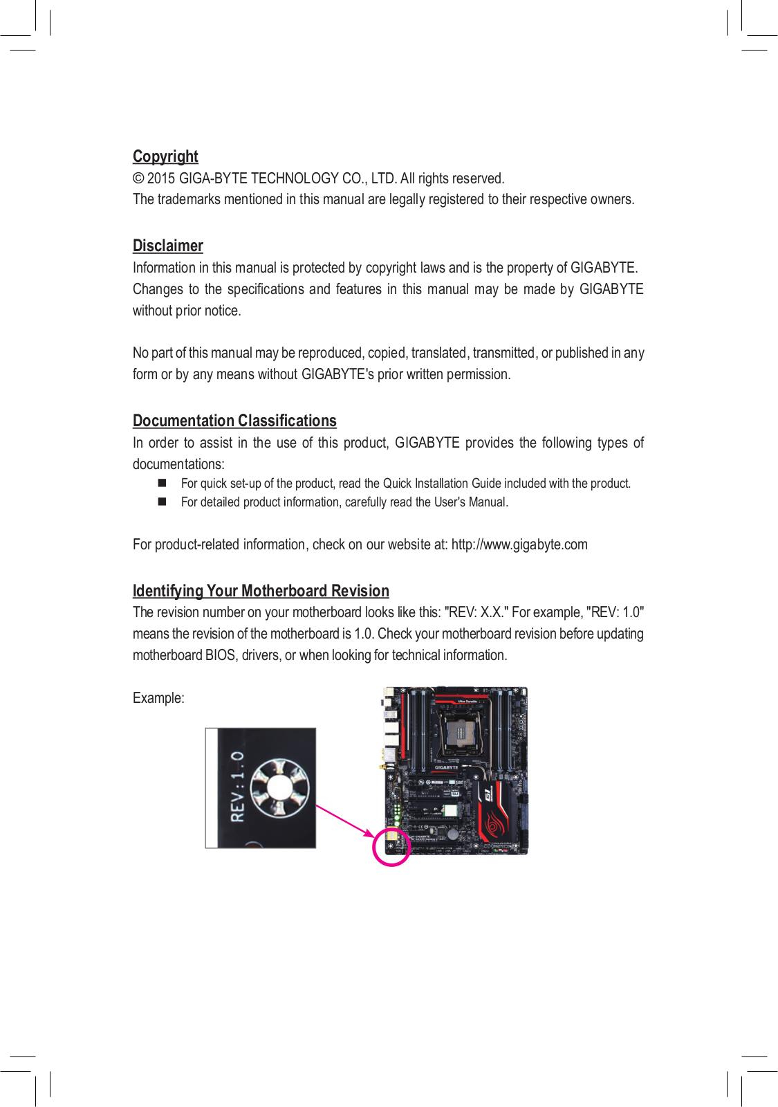
GA-Q67M-D2H-B3 (rev. 1.0)
GA-Q77M-D2H
3
GA-Q87M-D2H
2
GA-Q87M-MK
2
GA-Q87N
3
GA-Q87TN
2
GA-SBC7100
GA-SBC7300
GA-SBCAP3350
GA-SBCAP3450
GA-SBCAP3455
2
GA-SBCAP4200
GA-SINXP1394
8
GA-SINXP1394 (GA-8SQ800 ULTRA2)
GA-TG965MP-RH-GW
GA-VM800PMC
3
GA-VM900M
4
GA-VM900MC
2
GA-VT890P
5
GA-X150M-PRO ECC
GA-X150-PRO ECC
GA-X38-DQ6
4
GA-X38-DS4
3
GA-X38-DS5
2
GA-X38T-DQ6
4
GA-X48-DQ6
4
GA-X48-DS4
4
GA-X48-DS5
4
GA-X48T-DQ6
4
GA-X58A-OC
3
GA-X58A-UD3R
9
GA-X58A-UD3R (rev. 1.0)
GA-X58A-UD3R (rev. 2.0)
GA-X58A-UD5
13
GA-X58A-UD5 (rev. 1.0)
GA-X58A-UD5 (rev. 2.0)
GA-X58A-UD7
13
GA-X58A-UD7 (rev. 1.0)
GA-X58A-UD7 (rev. 2.0)
GA-X58A-UD9
15
GA-X58A-UD9 (rev. 1.0)
GA-X58-USB3
14
GA-X58-USB3 (rev. 1.0)
GA-X79S-UP5-WIFI
3
GA-X79-UD3
4
GA-X79-UD5
4
GA-X79-UD7
3
GA-X79-UP4
2
GA-X99-GAMING 5
4
GA-X99-GAMING 5P
4
GA-X99-GAMING 7 WIFI
2
GA-X99-GAMING G1 WIFI
4
GA-X99M-GAMING 5
3
GA-X99-SLI
GA-X99-SOC CHAMPION
GA-X99-SOC FORCE
3
GA-X99-UD3P
3
GA-X99-UD4
5
GA-X99-UD4P
5
GA-X99-UD5 WIFI
4
GA-X99-UD7 WIFI
3
GA-Z170-D3H
2
GA-Z170-GAMING K3
GA-Z170-HD3 DDR3
3
GA-Z170-HD3P
2
GA-Z170M-D3H
5
GA-Z170MX-GAMING 5
3
GA-Z170N-GAMING 5
3
GA-Z170X-GAMING 3
4
GA-Z170X-GAMING 5
4
GA-Z170X-GAMING 6
GA-Z170X-GAMING 7
2
GA-Z170X-GAMING G1
3
GA-Z170X-GAMING GT
2
GA-Z170XP-SLI
GA-Z170X-UD3
3
GA-Z170X-UD5
GA-Z270N-WIFI
GA-Z270P-D3
GA-Z270X-DESIGNARE
GA-Z270X-GAMINGK5
GA-Z270XP-SLI
GA-Z270X-ULTRAGAMING
GA-Z68A-D3-B3
6
GA-Z68A-D3H-B3
7
GA-Z68AP-D3
10
GA-Z68MA-D2H-B3
7
GA-Z68M-D2H
5
GA-Z68MX-UD2H-B3
7
GA-Z68P-DS3
7
GA-Z68XP-D3
4
GA-Z68XP-UD3
8
GA-Z68X-UD3-B3
6
GA-Z68X-UD3H-B3
7
GA-Z68X-UD3P-B3
6
GA-Z68X-UD3R-B3
5
GA-Z68X-UD4-B3
7
GA-Z68X-UD5-B3
6
GA-Z68X-UD7-B3
6
Loading...
Loading...
Nothing found
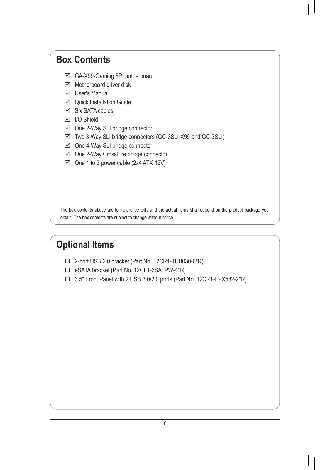
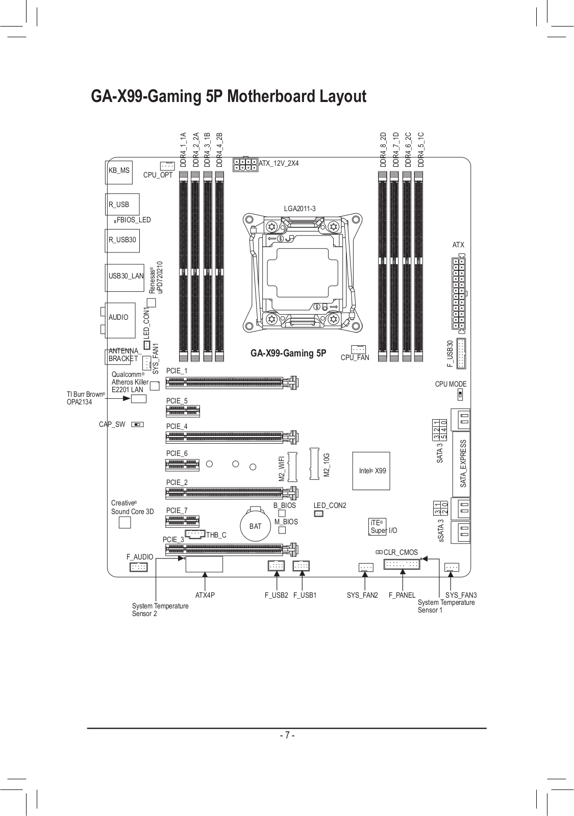
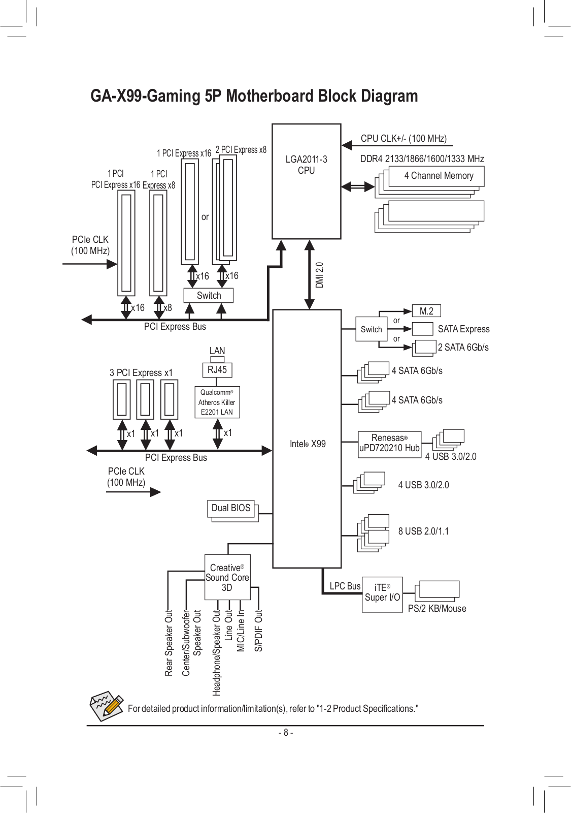
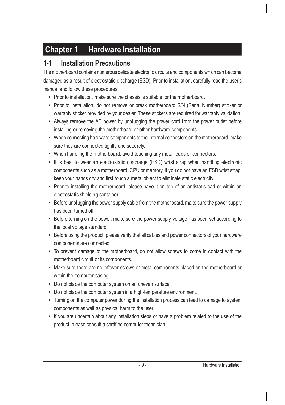
GA-X99-GAMING 5P
User Manual
128 pgs
59.09 Mb
0
User Manual [ja]
128 pgs
59.63 Mb
0
User Manual [zh]
132 pgs
54.65 Mb
0
User Manual [ko]
128 pgs
59.33 Mb
0
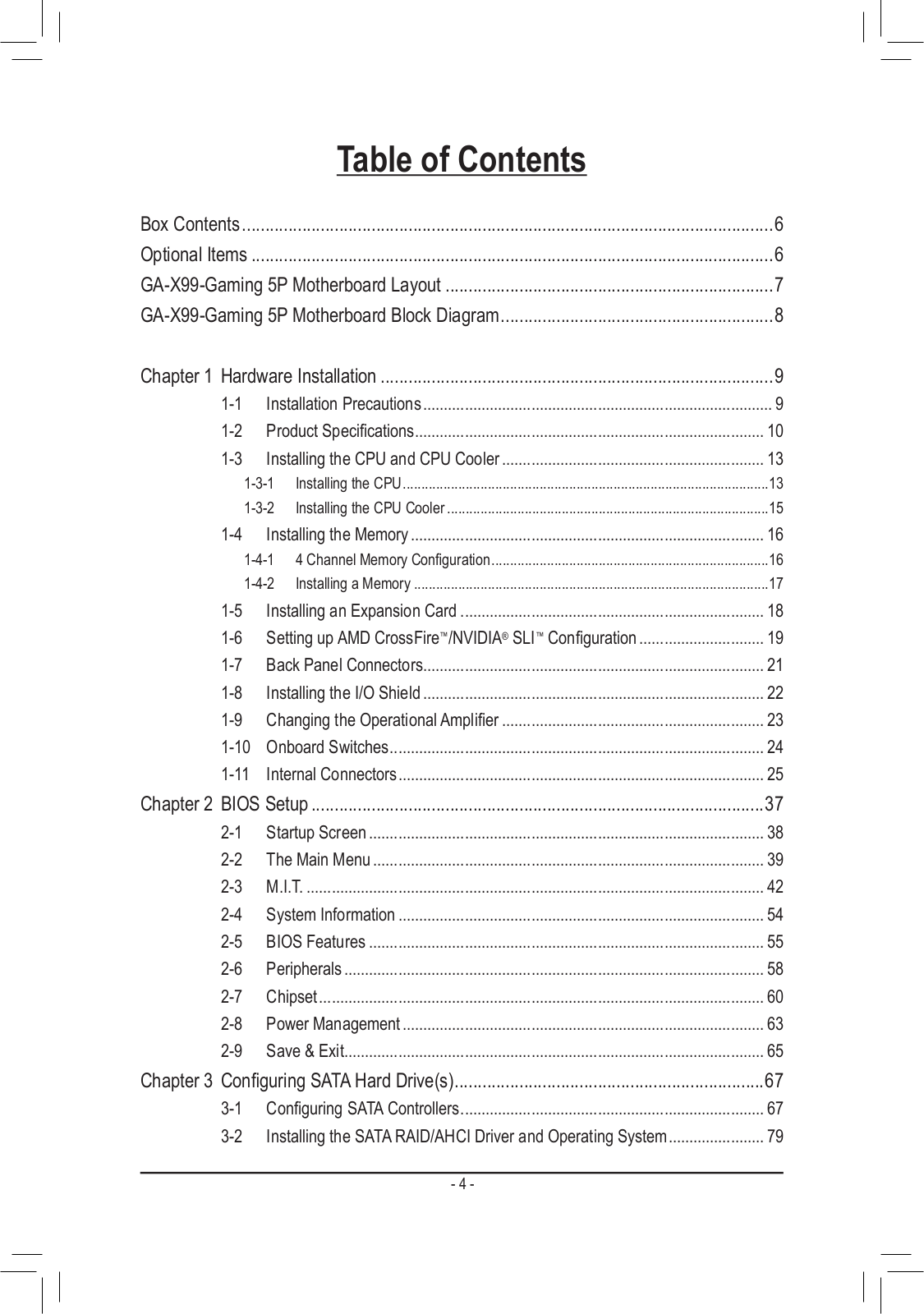
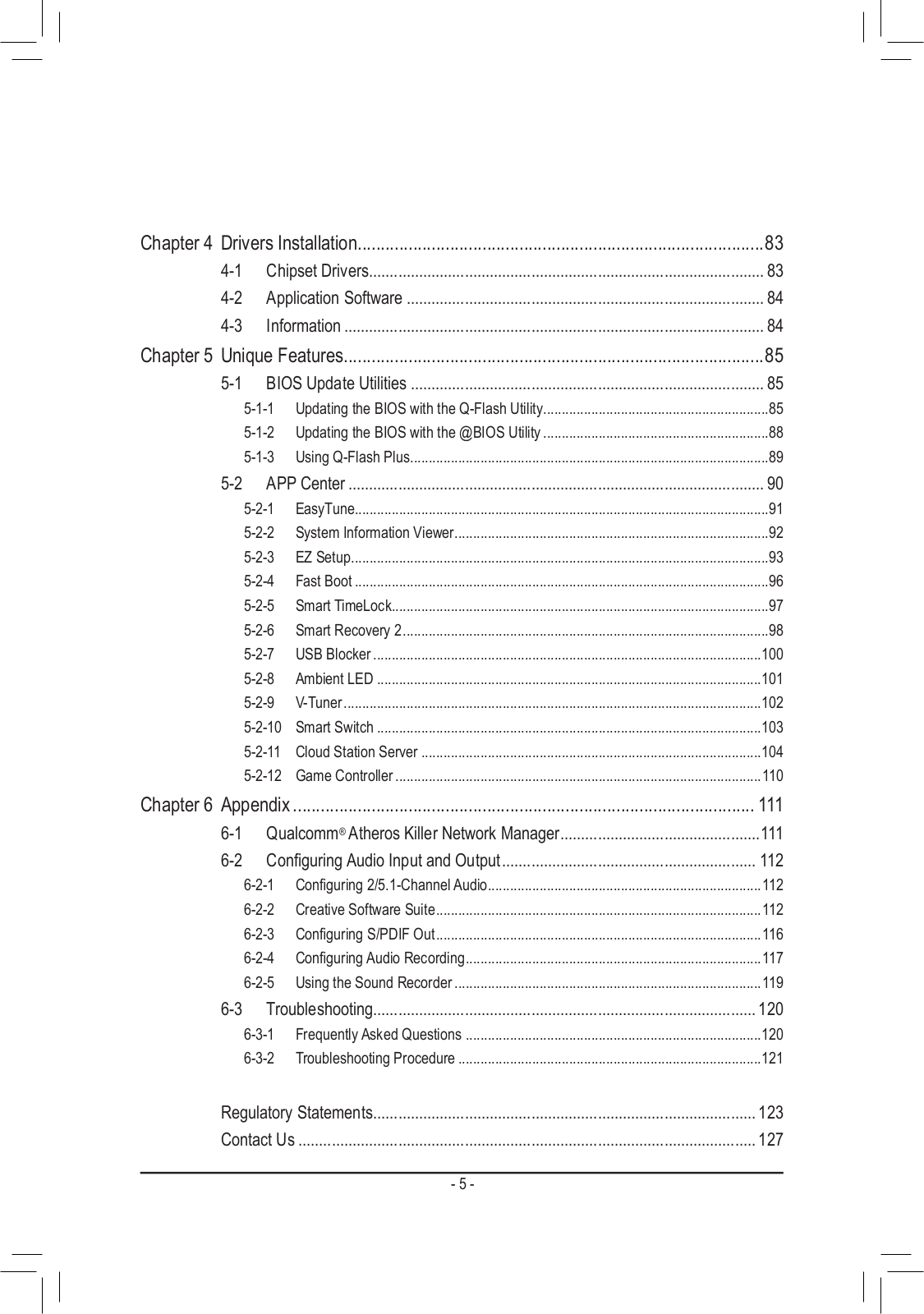
Table of contents
Loading...
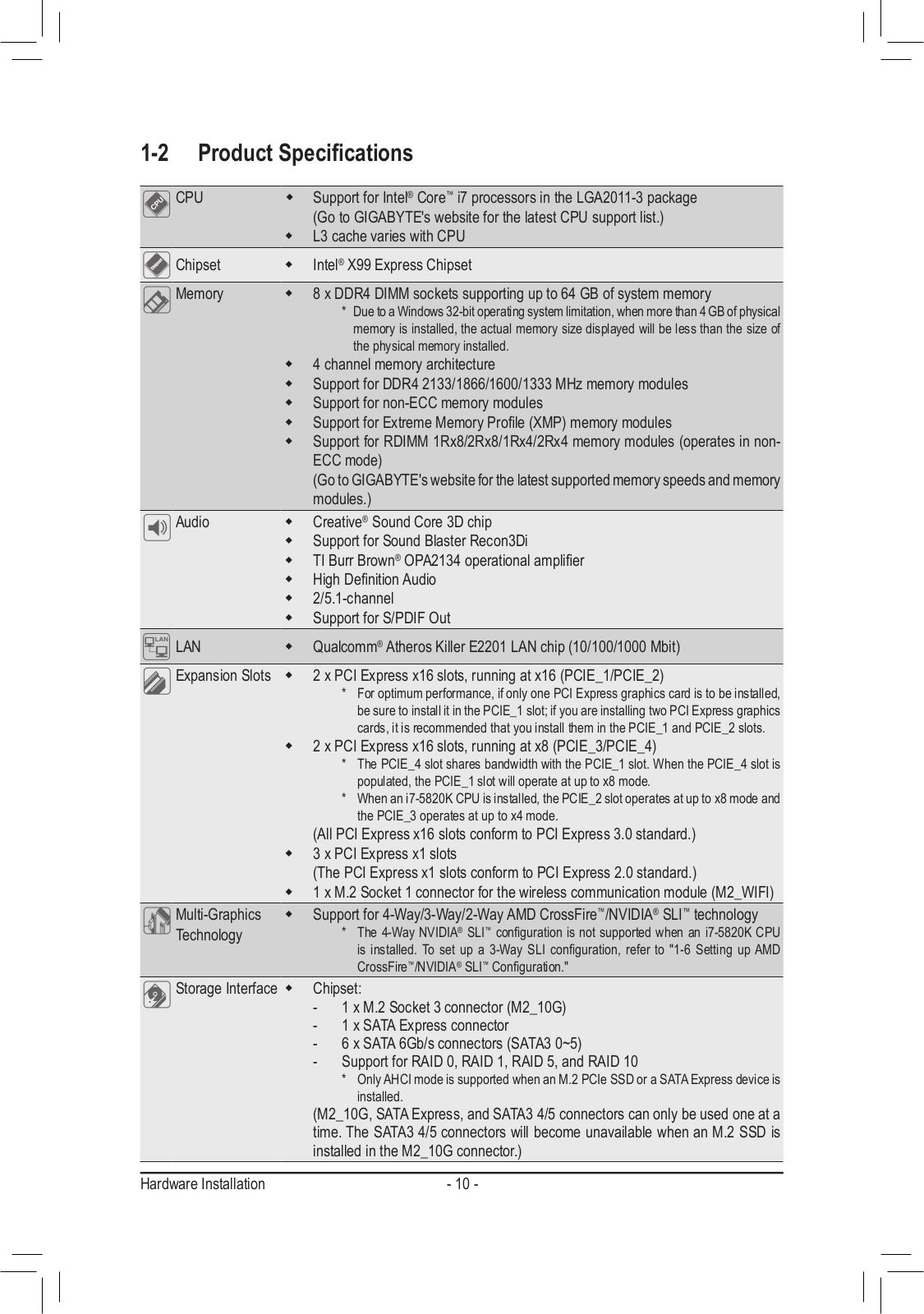
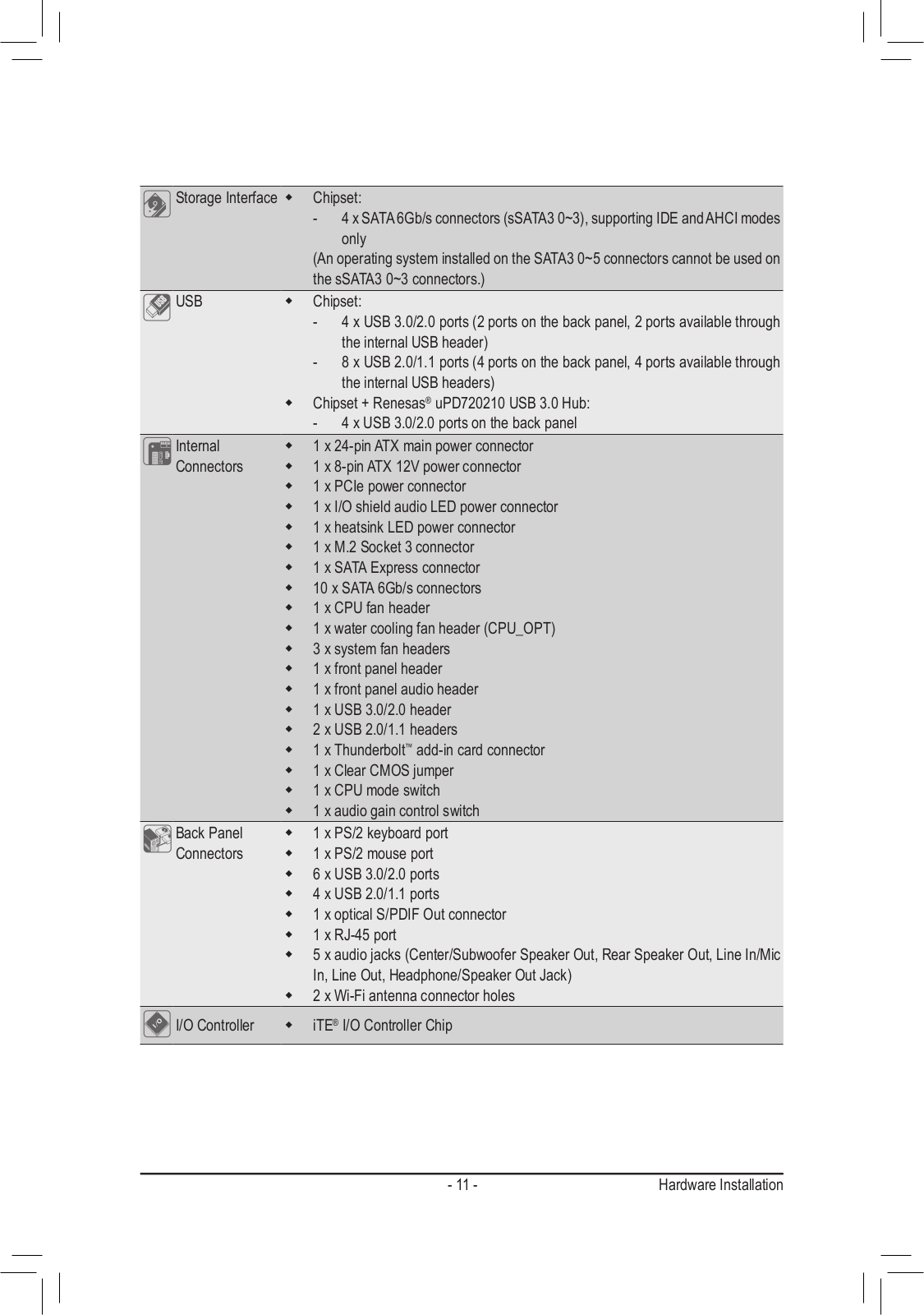
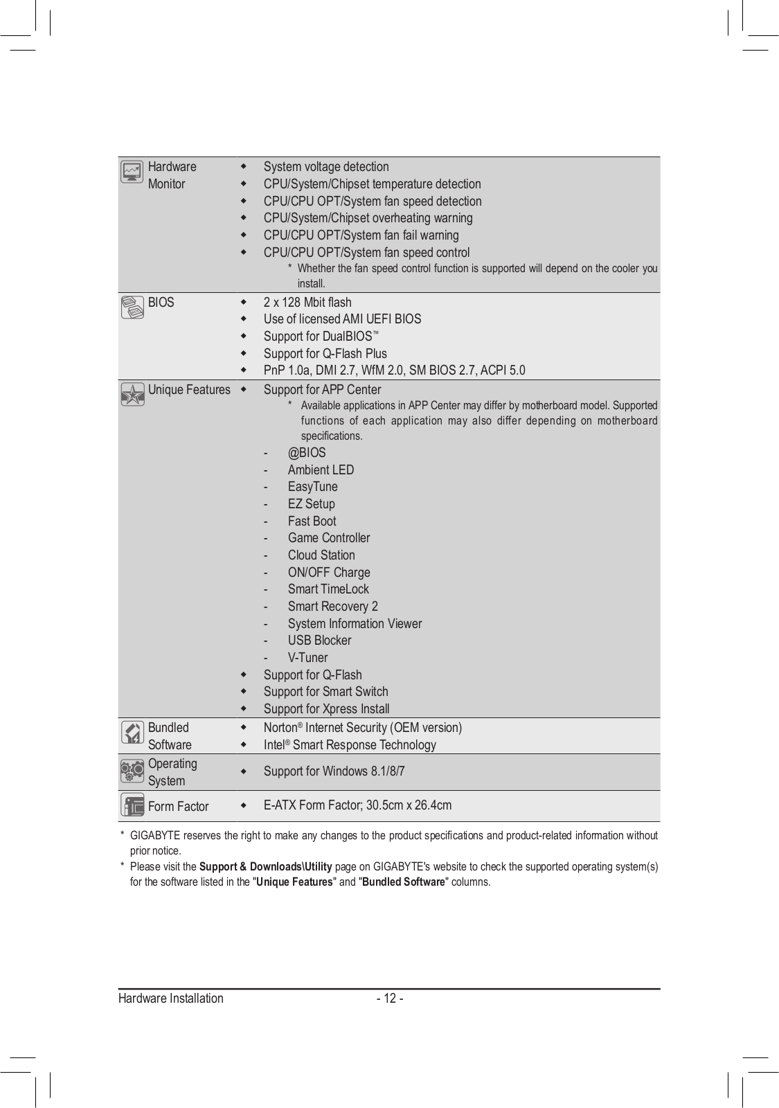
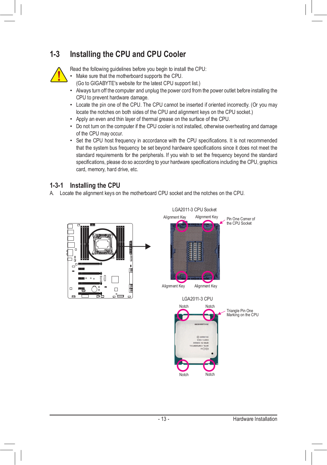
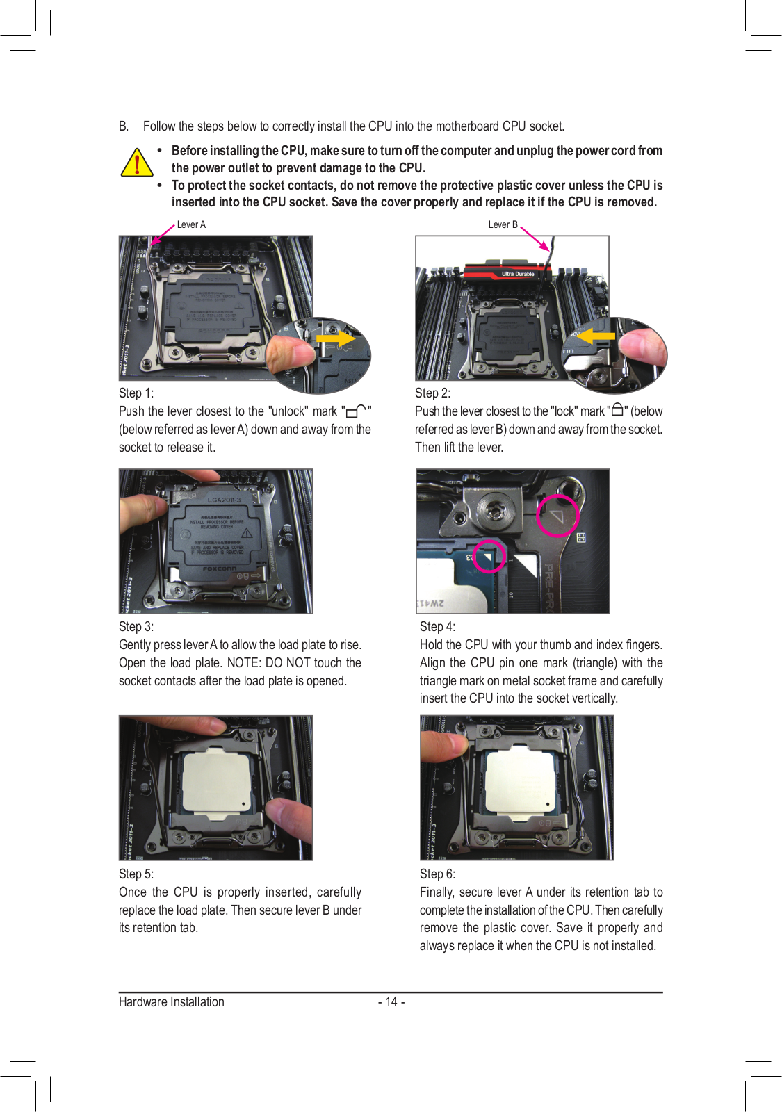
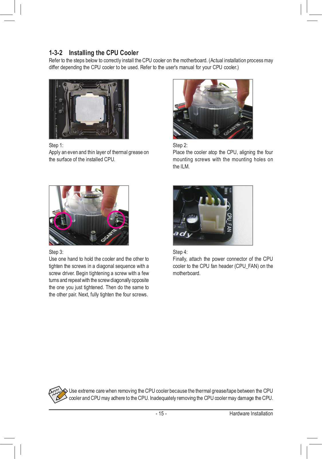
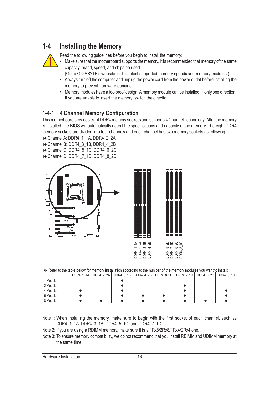
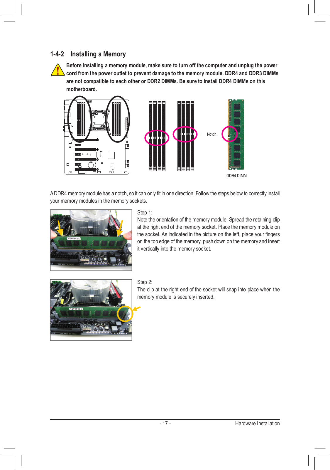
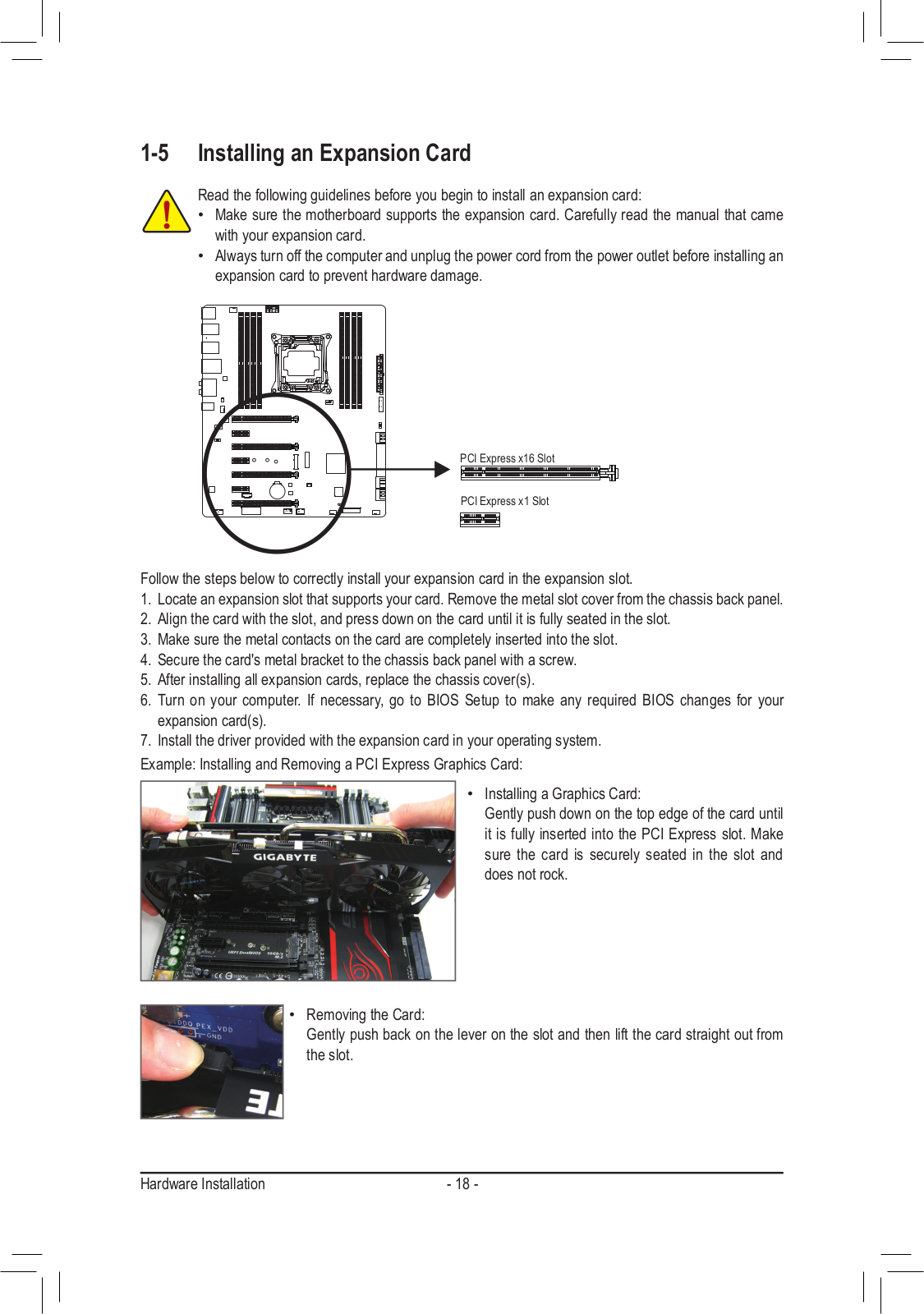
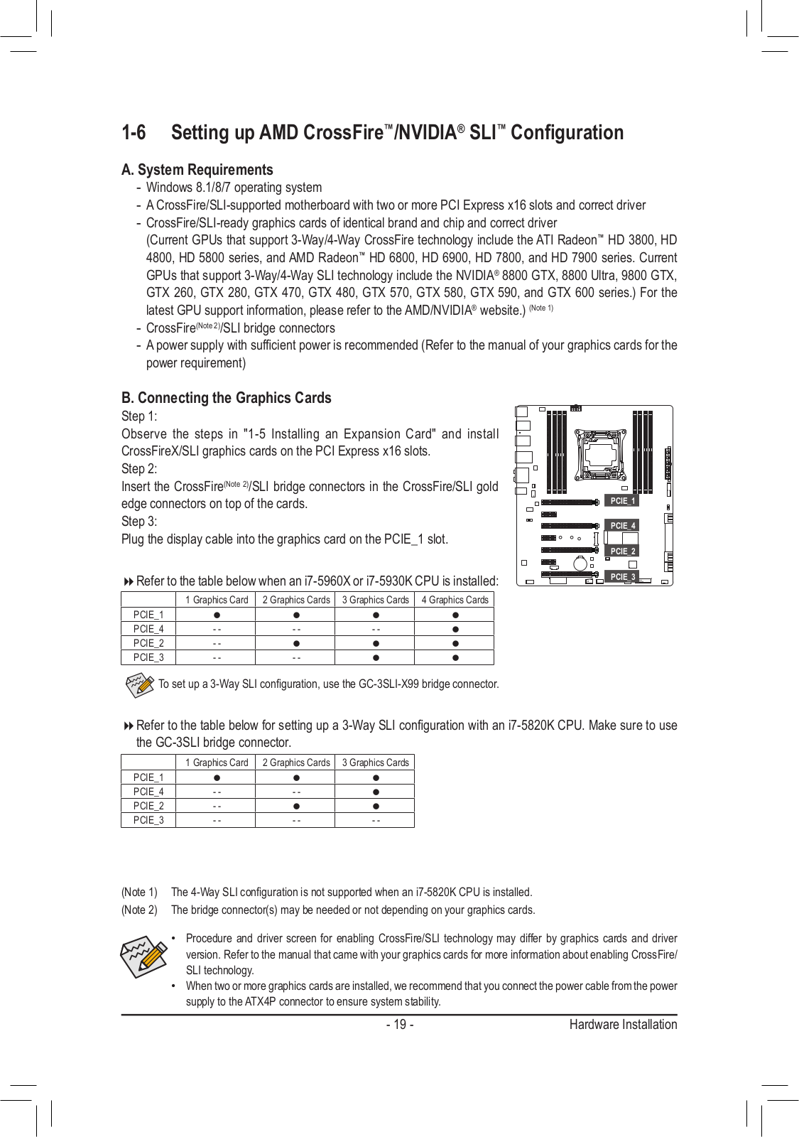
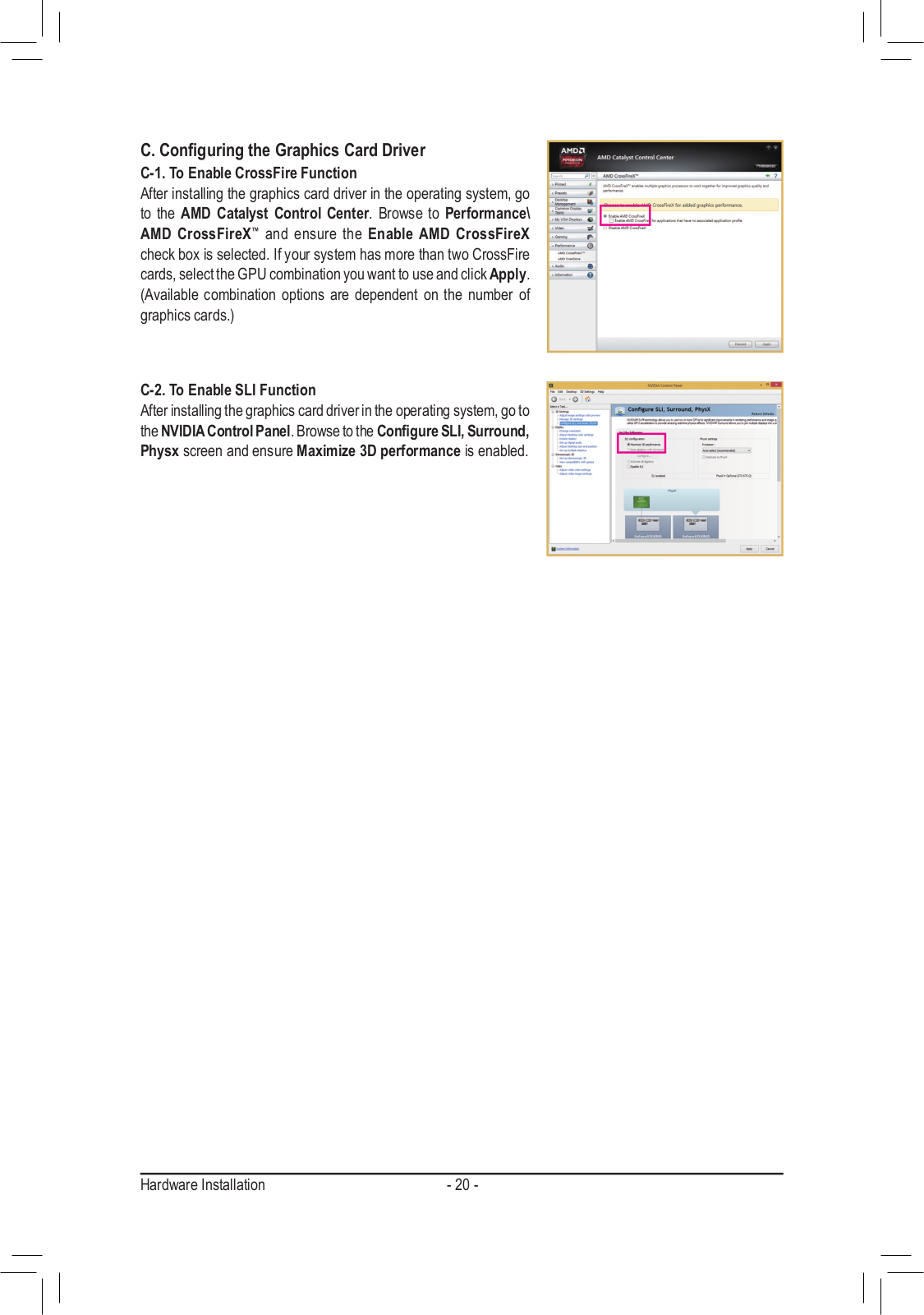
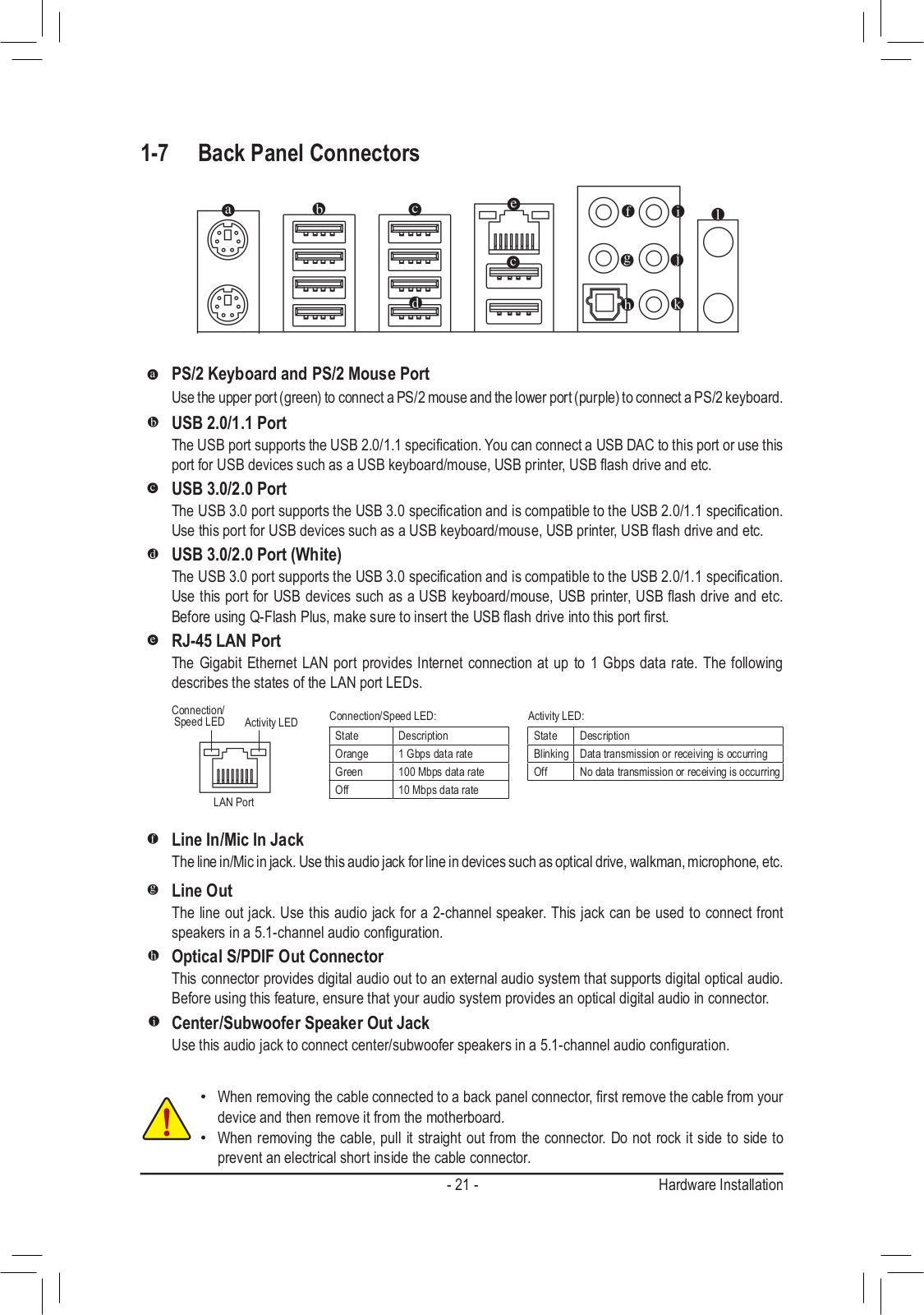
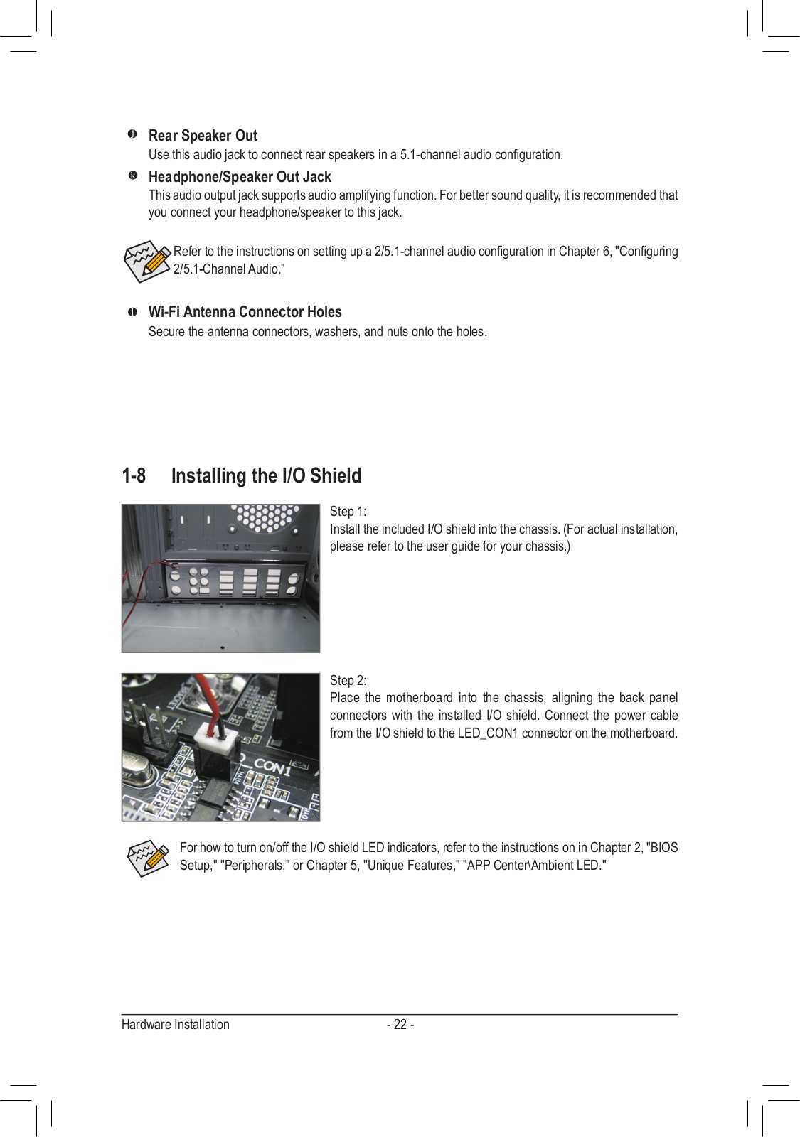
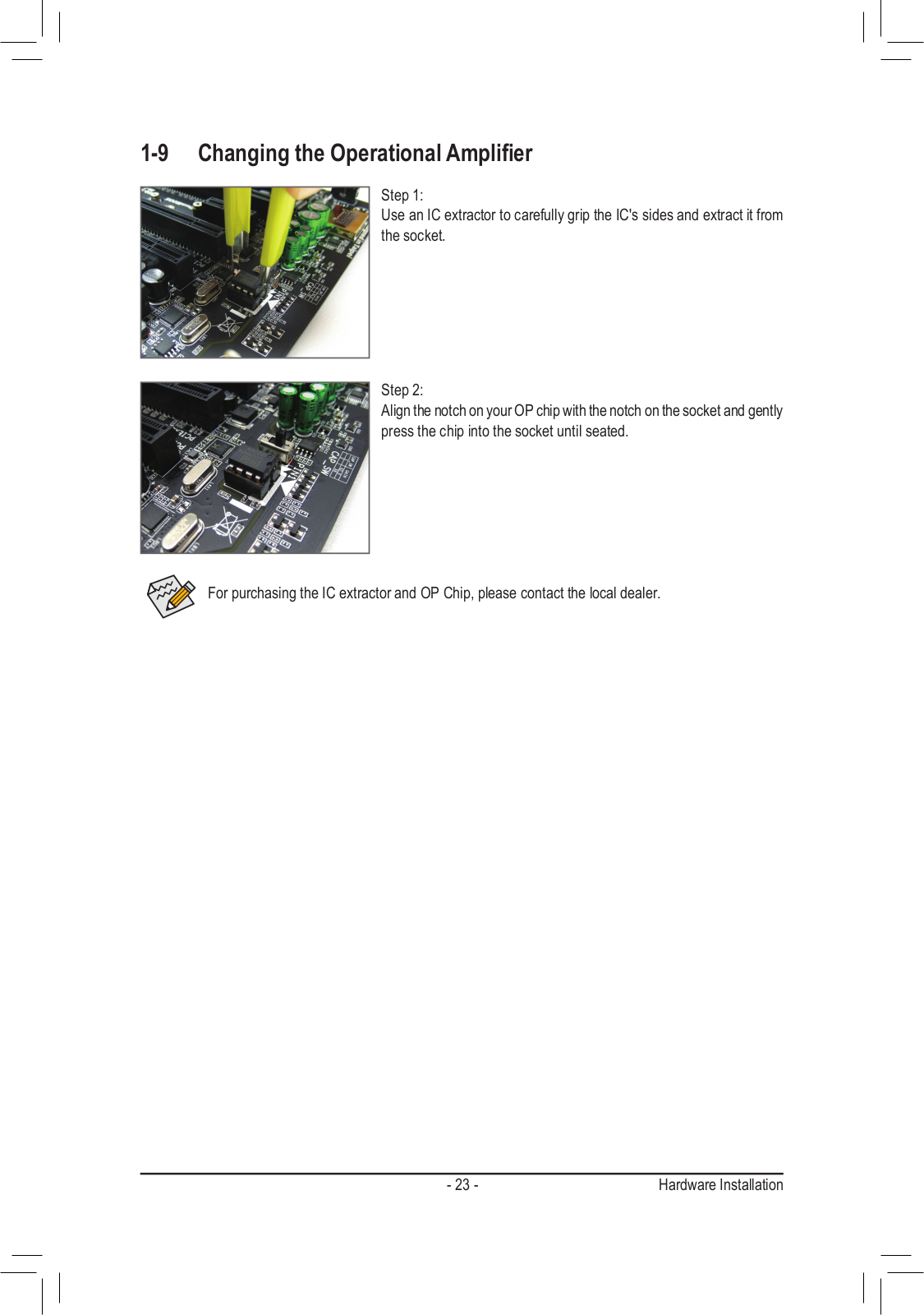
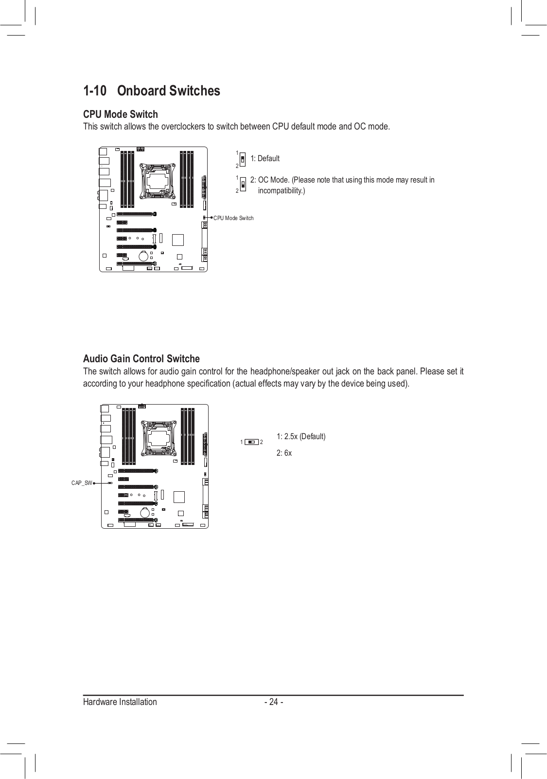
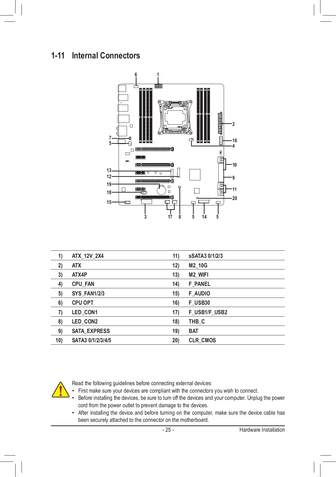
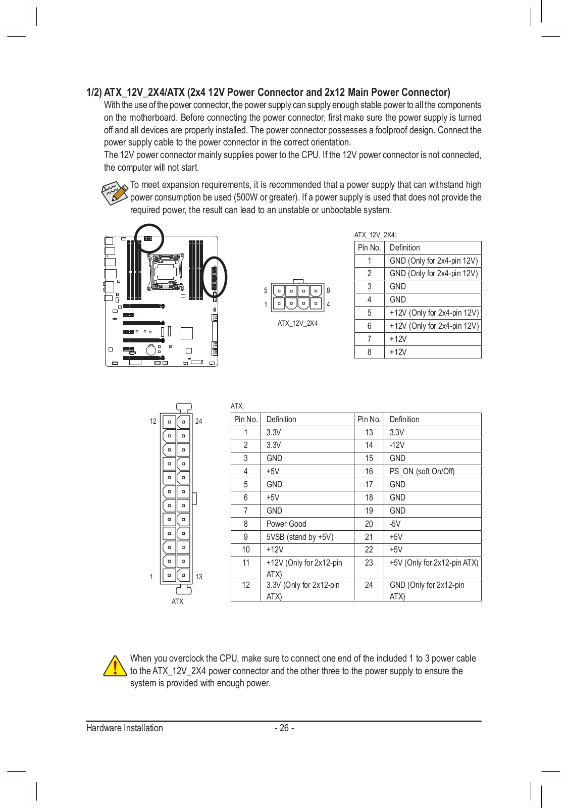
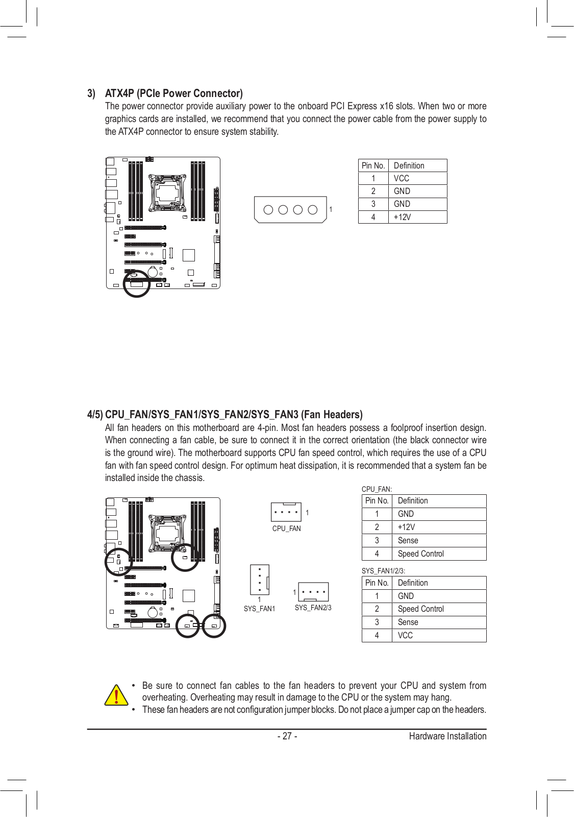
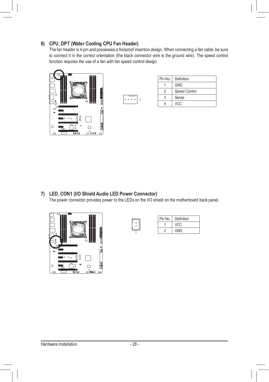
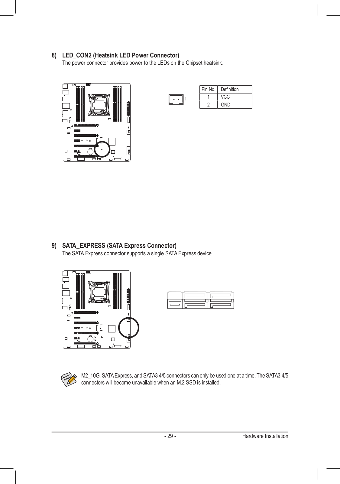
Gigabyte GA-X99-GAMING 5P User Manual
...
Gigabyte User Manual
Download
Specifications and Main Features
Frequently Asked Questions
User Manual
Download
Loading...
+
98
hidden pages
Unhide
You need points to download manuals.
1 point = 1 manual.
You can buy points or you can get point for every manual you upload.
Buy points
Upload your manuals
 Loading...