

Page 1
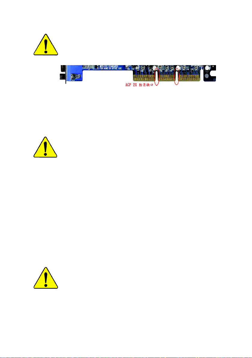
當您安裝AGP卡時,請注意下述注意事項。
您的顯示卡若有AGP 4X/8X 防呆缺口(如下圖),請再次確認此
卡的規格為AGP 4X/8X(1.5V)。
AGP 4X/8X 防呆缺口
不要使用AGP 2X 卡,因為SiS® 655晶片組不支援AGP 2X,若
您使用AGP 2X 卡時,可能造成系統無法正常開機的情況,
所以請使用AGP 4X/8X卡。
範例一:Diamond Vipper V770 這塊顯示卡的金手指部份設計成
2X/4X 插槽皆可使用,透過Jumper 可切換於2X 或4X ,出廠預
設值為2X(3.3V),若您使用此卡在GA-SINXP1394 主機板上,而
且沒有將Jumper切換至4X (1.5V)的模式時,可能造成系統無法
正常開機的情況。
範例二:某些SiS 305 及Power Color 所生產的某些ATi Rage 128
Pro 等顯示卡的金手指部份設計成2X/4X插槽皆可使用,但只支
援2X(3.3V),若您使用此卡在GA-SINXP1394 主機板上,可能造
成系統無法正常開機的情況。
注意:技嘉科技所生產的AG32S(G)顯示卡,雖然採用ATi Rage
128 Pro晶片,但此卡設計符合AGP4X的規格,因此不會發生如
範例二中可能造成系統無法正常開機的情況,請您安心使用。
當您在安裝PCI 設備前,若有發現PCI 擴充槽上有Dual BIOS貼
紙,請先移除此貼紙。
Page 2
本手冊所有提及之商標與名稱皆屬該公司所有。
在科技迅速的發展下,此發行手冊中的一些規格可能會
有過時不適用的敘述,敬請見諒。
在此不擔保本手冊無任何疏忽或錯誤亦不排除會再更新
發行。手冊若有任何內容修改,恕不另行通知。
主機板上的任何貼紙請勿自行撕毀,否則會影響到產品
保固期限的認定標準。
Page 3

Ausschla ger Weg 41, 1F, 20537 Hamburg, Germany
( description of the apparatus, system, installation to which it refers)
(reference to the specification under which con formity is declared)
in accordance with 89/336 EEC-EMC Directive
o EN 55011 Limits and methods of measurement
o EN 55013
o EN 55014 Limits and methods of measurement
o EN 55015 Limits and methods of measurement
o EN 55020
T EN 55022 Limits and methods of measurement
o DIN VDE 0855
o part 10
o part 12
T CE marking
o EN 60065
o EN 60335
of radio disturbance characteristics of
industrial,scientific and medical (ISM
high frequency equipment
Limits and methods of measurement
of radio disturbance characteristics of
broadcast receivers and associated
equipment
of radio disturbance characteristics of
household electrical appliances,
portable tools and similar electrical
apparatus
of radio disturbance characteristics of
fluorescent lamps and luminaries
Immunity from radio interference of
broadcast receivers and associated
equipment
of radio disturbance characteristics of
information technology equipment
Cabled distribution systems; Equipment
for receiving and/or distribution from
sound and television signals
The manufacturer also declares the conformity of above mentioned product
with the actual required safety standards in accordance with LVD 73/23 EEC
Safety requirements for mains operated
electronic and related apparatus for
household and similar general use
Safety of household and similar
electrical appliances
(Stamp)
Declaration of Conformity
We, Manufacturer/Importer
(full address)
G.B.T. Technology Träding GMbH
declare that the product
Mother Board
GA-SINXP1394
is in conformity with
o EN 61000-3-2*
T EN 60555-2
o EN 61000-3-3* Disturbances in supply systems cause
T EN 60555-3
T EN 50081-1
T EN 50082-1
o EN 55081-2
o EN 55082-2
o ENV 55104
o EN50091-2
(EC conformity marking)
o EN 60950
o EN 50091-1
Manufacturer/Importer
Date : January 6, 2002
Disturbances in supply systems cause
by household appliances and similar
electrical equipment “Harmonics”
by household appliances and similar
electrical equipment “Voltage fluctuations”
Generic emission standard Part 1:
Residual commercial and light industry
Generic immunity standard Part 1:
Residual commercial and light industry
Generic emission standard Part 2:
Industrial environment
Generic emission standard Part 2:
Industrial environment
lmmunity requirements for household
appliances tools and similar apparatus
EMC requirements for uninterruptible
power systems (UPS)
Safety for information technology equipment
including electrical bussiness equipment
General and Safety requirements for
uninterruptible power systems (UPS)
Signature:
Name:
Timmy Huang
Timmy Huang
Page 4

DECLARATION OF CONFORMITY
Per FCC Part 2 Section 2.1077(a)
Responsible Party Name:
Add ress:
Phone/Fax No:
hereby declares that the product
Produ ct Name:
Model Nu mber:
Conforms to the following specifications:
FCC Part 15, Subpart B, Section 15.107(a) and Section 15.109
(a),Class B Digital D evice
Supplementary Information:
This device complies with part 15 of the FCC Rules. Operation is
subject to the following two conditions: (1) This device may not
cause harmful and (2) this device must accept any inference received,
including that may cause undes ired operation.
Representative Person’s Name:
Signature:
G.B.T. INC. (U .S.A.)
17358 Railroad Street
City of Indu stry, CA 91748
(818) 854-9338/ (818) 854-9339
Motherboard
GA-SINXP1394
ERIC LU
Eric Lu
Date:
January 6, 2002
Page 5

GA-SINXP1394
P4 泰坦DDR 主機板
中文安裝使用手冊
®
Pentium
4處理器主機板
Rev. 1001
12MC-SINXP-1001
Page 6

繁
體
中
文
目錄
清點附件 ......................................................................... 4
警告標語 ......................................................................... 4
第一章 序言.................................................................... 5
特色彙總 ........................................................................................................ 5
GA-SINXP1394 主機板 Layout 圖 ................................................................ 8
第二章 硬體安裝步驟 .................................................. 9
步驟 1 :安裝中央處理器(CP U) ........................................................... 10
步驟1-1:中央處理器之安裝........................................................................................10
步驟1-2:中央處理器之散熱裝置安裝 ..................................................................... 11
步驟 2 :安裝記憶體模組..................................................................... 12
步驟 3 :安裝介面卡............................................................................... 14
步驟3-1:AGP卡之安裝 .................................................................................................14
步驟3-2:DPVRM(Dual Power Voltage Regulator Module) 之安裝 ............................... 15
步驟 4 :連接所有訊號線、排線、電源供應線及面板控制線16
步驟4-1:後方I/O裝置鐵片介紹 .................................................................................16
步驟4-2:插座及跳線介紹 ............................................................................................18
第三章BIOS 組態設定 ................................................ 29
主畫面功能(BIOS 範例版本:F1) ....................................................... 3 0
標準 CMOS 設定......................................................................................... 32
進階 BIOS 功能設定 ................................................................................. 35
整合週邊設定 ............................................................................................ 38
省電功能設定 ............................................................................................ 42
- 2 -GA-S INXP1394 主機板
Page 7

隨插即用與PCI 組態設定 ..................................................................... 4 4
電腦健康狀態 ............................................................................................ 45
頻率 / 電壓控制 .......................................................................................... 47
最高效能 ...................................................................................................... 49
載入 Fail-Safe 預設值 ................................................................................ 50
載入 Optimized 預設值 .............................................................................. 51
設定管理者 (Supervisor)/ 使用者(User)密碼 ...................................... 52
離開 SETUP 並儲存設定結果 .............................................................. 5 3
離開 SETUP 但不儲存設定結果 ......................................................... 5 4
第四章 技術文件參考資料 ....................................... 57
晶片組功能方塊圖 .................................................................................. 57
Easy Tune
@ BIOS
DPS (Dual Power System)雙迴路電源系統介紹................................. 60
Dual BIOS/Q-Flash 功能介紹 .................................................................... 61
二聲 / 四聲 / 六聲道音效功能介紹 .................................................... 82
TM
4 介紹 ...................................................................................... 5 8
TM
介紹 .............................................................................................. 5 9
繁
體
中
文
第五章 附錄.................................................................. 89
目錄- 3 -
Page 8
繁
清點附件
體
中
文
GA-SINXP1 394 主機板一片 2 埠通用串列埠插座排線 x 1
主機板驅動程式光碟片 4 埠通用串列埠插座排線 x 1
GA-S INXP1394 中文安裝手冊 SAT A 插座排線 x2
電腦組裝秘笈 SPDIF Kit x1(SPD-KIT)
ITE RAID 使用手冊 後方I/O 裝置鐵片
SATA RAID 使用手冊 Motherboard Settings 貼紙
IDE 插座排線 x 3 / 軟碟插座排線 x 1 GC-S139 4 卡(選購配備)
GC-S ATA 卡 (選購配備) (使用手冊)
(使用手冊;SATA 排線 x1;電源連接線 x 1)
警告標語
主機板由許多精密的積體電路及其他元件所構成,這些積體電路很容易因為遭到靜
電影響而損失。所以請在正式安裝前,做好下列準備。
1. 請將電腦的電源關閉,最好拔除電源插頭。
2. 拿取主機板時請儘量避免觸碰金屬接線部份。
3. 拿取積體電路元件(CPU、RAM)時,最好能夠戴上有防靜電手環。
4. 在積體電路未安裝前,需將元件置放在靜電墊或防靜電袋內。
5. 當您將主機板中的ATX電源供應器插座上的插頭拔除時,請確認電源供應器
的開關是關閉狀況。
安裝主機板至機殼中…
大多數電腦機殼的底部會有多個固定孔孔位,可使主機板確實固定並且不會短
路。請小心不要讓螺絲接觸到任何PCB板上的線路或零件,當印刷電路主機板表面
線路接近固定孔時,您可使用塑膠墊片來讓螺絲與主機板表面隔離過,避免造成主
機板損壞或故障。
- 4 -GA-S INXP1394 主機板
Page 9

第一章 序言
繁
特色彙總
規格 l 主機板採四層設計ATX規格30.5公分x 24.4公分
中央處理器 l Socket478支援最新Intel Micro FC-PGA2 Pentium®4處理器
l 支援Intel
l 支援Intel
l Intel Pentium®4 400/533MHz FSB
l 2nd快取記憶體取決於CPU
晶片組 l SiS 655 Host/Memory controller
l SiS 963 MuTIOL Media I/O
記憶體 l 4 184-pin DDR DIMM 插槽
l 支援雙向DDR400
l 支援128MB/256MB/512MB/1GB unbuffered 記憶體
l 最大支援到4GB
l 僅支援2.5V DDR DIMM
I/O控制器 l IT8705F
擴充槽 l 1 組通用的AGP 3.0擴充槽,支援AGP 8X/4X模式
l 5 PCI擴充槽支援33MHz及PCI2.2 compliant
內建IDE l 2 IDE (IDE1,IDE2) bus master (UDMA 33/ATA 66/ATA 100/ATA133)
IDE埠可連接4 ATAPI裝置
l IDE3 及IDE4 適用於RAID ,Ultra ATA-133 ,Ultra ATA-100**
Serial ATA l 2 Serial ATA connectors in 150 MB/s operation mode
l Controlled by Silicon Image SiI3112A
®
Pentium
®
®
4 (Northwood, 0.13 m) 處理器
Pentium ® 4 Processor with HT Technology
<註1>
/DDR333/DDR266 DIMM
體
中
文
續下頁.......
<註1> 經我們認證過DDR400記憶體模組的詳細資料,請至技嘉網站查詢。
- 5 -
序言
Page 10

繁
體
中
文
內建周邊設備 l 1個軟碟插座支援兩台磁碟機(360K,720K,1.2M,1.44M
及2.88M bytes)
l 1組並列埠插座可支援Normal/EPP/ECP模式
l 2組串列埠插座(COM A & COM B)
l 支援USB 2.0/1.1 (6組USB埠插座,後端通用串列埠 x 2,
前端通用串列埠 x 4)
l 1組第二組音源插座
l 1個紅外線連接端
硬體監控 l CPU/系統風扇運轉偵測
l CPU/系統風扇故障警告功能
l 偵測 CPU過溫警告
l 系統電壓自動偵測
內建音效晶片 l CODEC音效晶片 (RealTek ALC650)
l Line Out : 2 組前置喇叭
l Line In : 2 組後置喇叭(由軟體切換)
l Mic In : 中置/重低音(由軟體切換)
l SPDIF out / SPDIF IN
l CD In/AUX_In/Game Port
內建 RAID功能 l ITE IT8212F
l 支援資料striping (RAID 0) 或mirroring (RAID 1)或
striping+mirroring (RAID 0+RAID 1)
l 支援JBOD功能
l 支援雙ATA133 IDE通道並行作業
l 支援 ATAPI 模式的硬碟
l 符合IDE bus master標準
l 支援 ATA133/RAID 模式 (由BIOS切換)
l 開機時顯示狀態及錯誤檢查訊息
l Mirroring 功能支援自動背景重建
l 內建的BIOS具備LBA與延伸中斷13h磁碟機容量轉換
內建網路晶片 l 內建Intel® RC82540EM(KENAI 32)晶片
l 1 RJ45 port
續下頁.......
- 6 -GA-S INXP1394 主機板
Page 11
PS/2插座 l PS/2鍵盤插座及PS/2滑鼠插座
BIOS l 使用經授權 AWARD BIOS,2M bit快閃記憶體
l 支援更新BIOS功能
l 支援雙BIOS(DualBIOS)
附加特色 l PS/2 鍵盤開機
l PS/2滑鼠開機
l 支援STR功能(Suspend-To-RAM)
l AC Recovery
l 鍵盤過電流保護
l 經由USB鍵盤 /滑鼠將系統從 S3喚醒
l 支援@BIOS
l 支援Easy Tune 4
無跳線帽超頻功能 l Over 電壓 (CPU/DRAM/AGP) by BIOS
支援HT功能條件如下:
您的電腦系統必須支援以下元件才能確定啟動Hyper-Threading Technology
- CPU: An Intel® Pe ntium 4 Processor with HT Technolo gy
- Chipset: An SiS® Chipset that suppo rts HT Technol ogy
- BIOS : A BIOS that s upports HT Technology and has it enabled
- OS: An operation s ystem that has optimizations for HT Techno logy
繁
體
中
文
請依據您CPU的規格來設定CPU 的頻率,我們不建議您將系統速度設定超
過硬體之標準範圍,因為這些規格對於周邊設備而言並不算是符合標準規
格。如果您要將系統速度設定超出標準規格,請評估您的硬體規格,例
如:CPU、顯示卡、記憶體、硬碟來設定。
- 7 -
序言
Page 12
繁
體
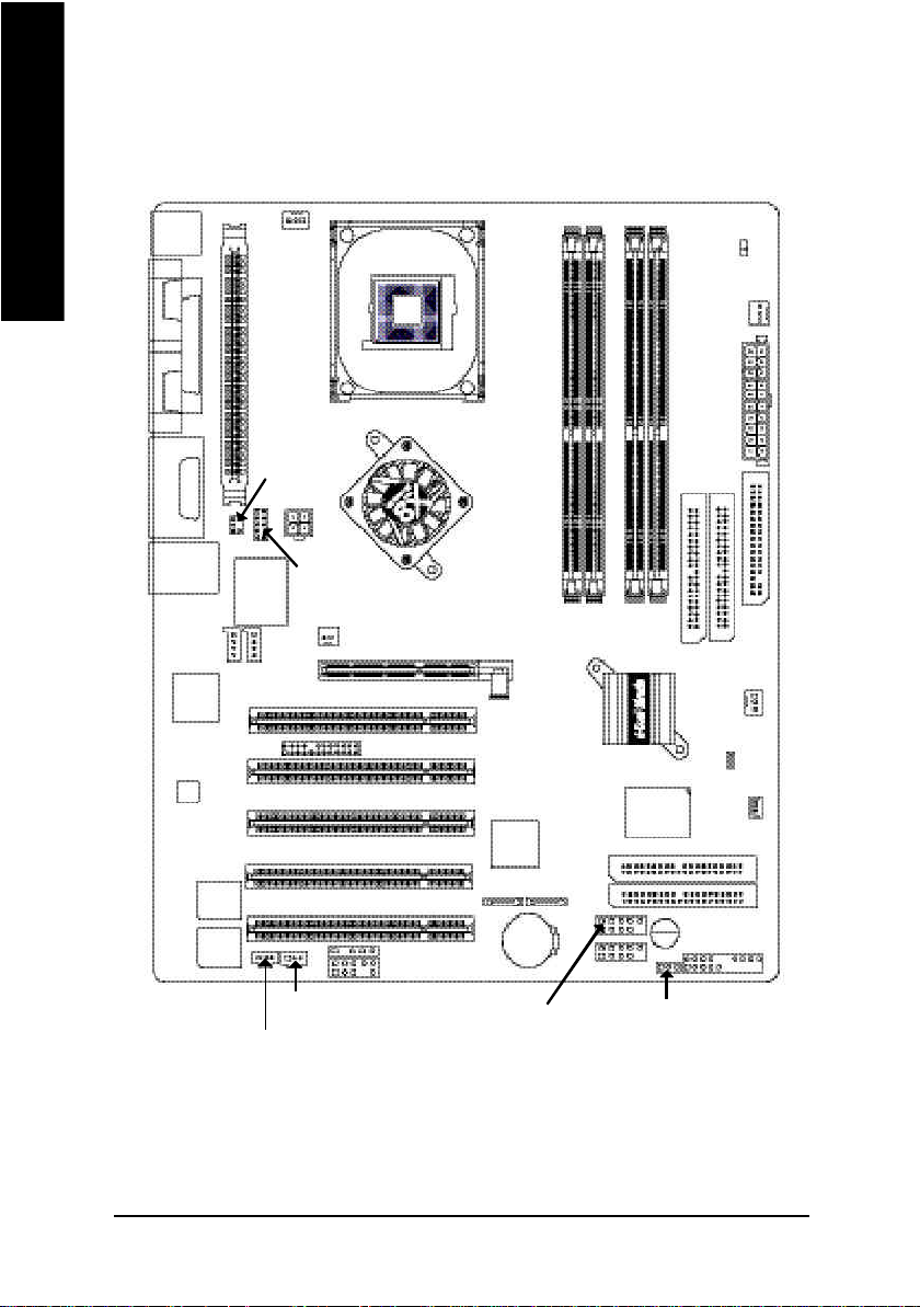
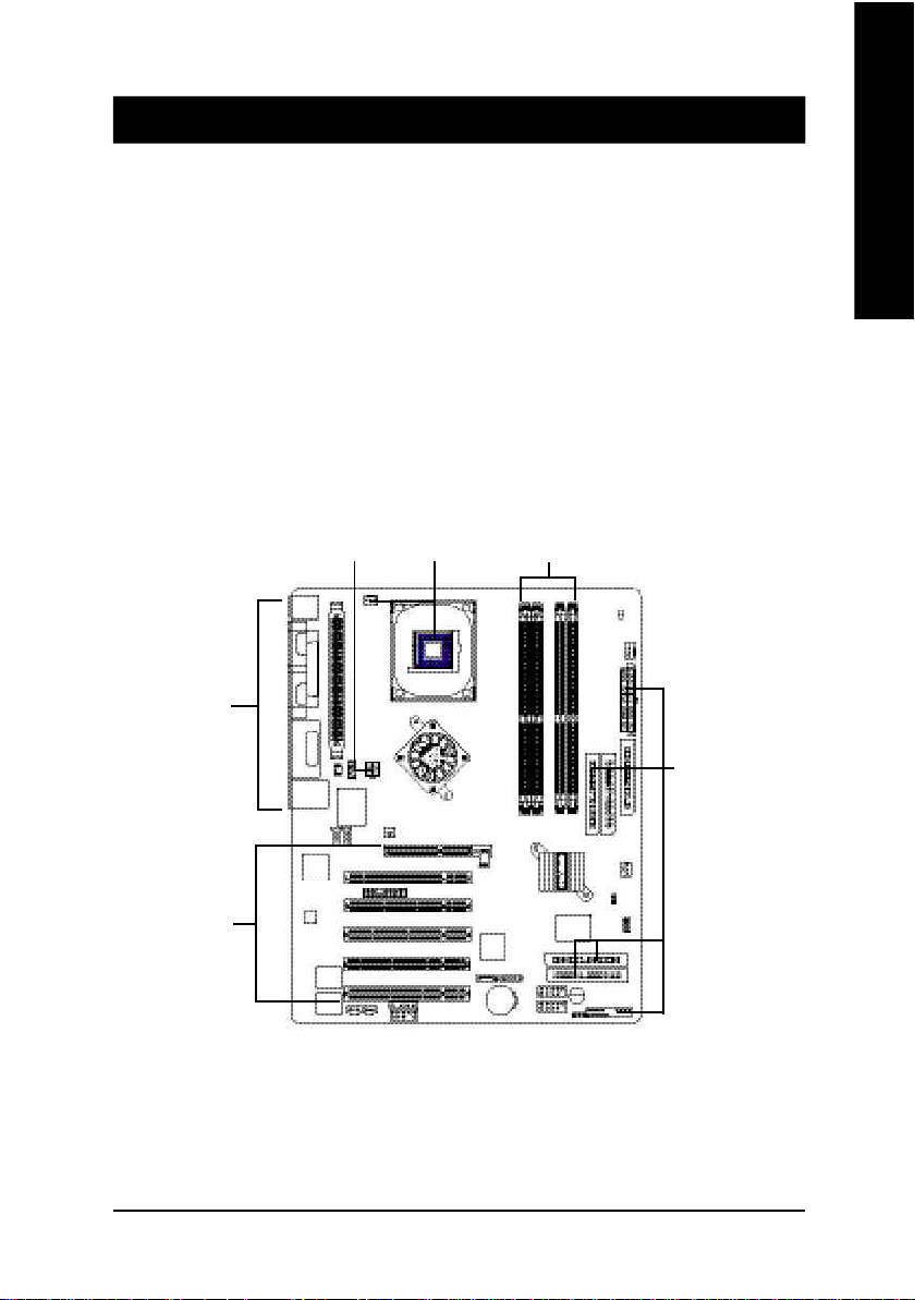
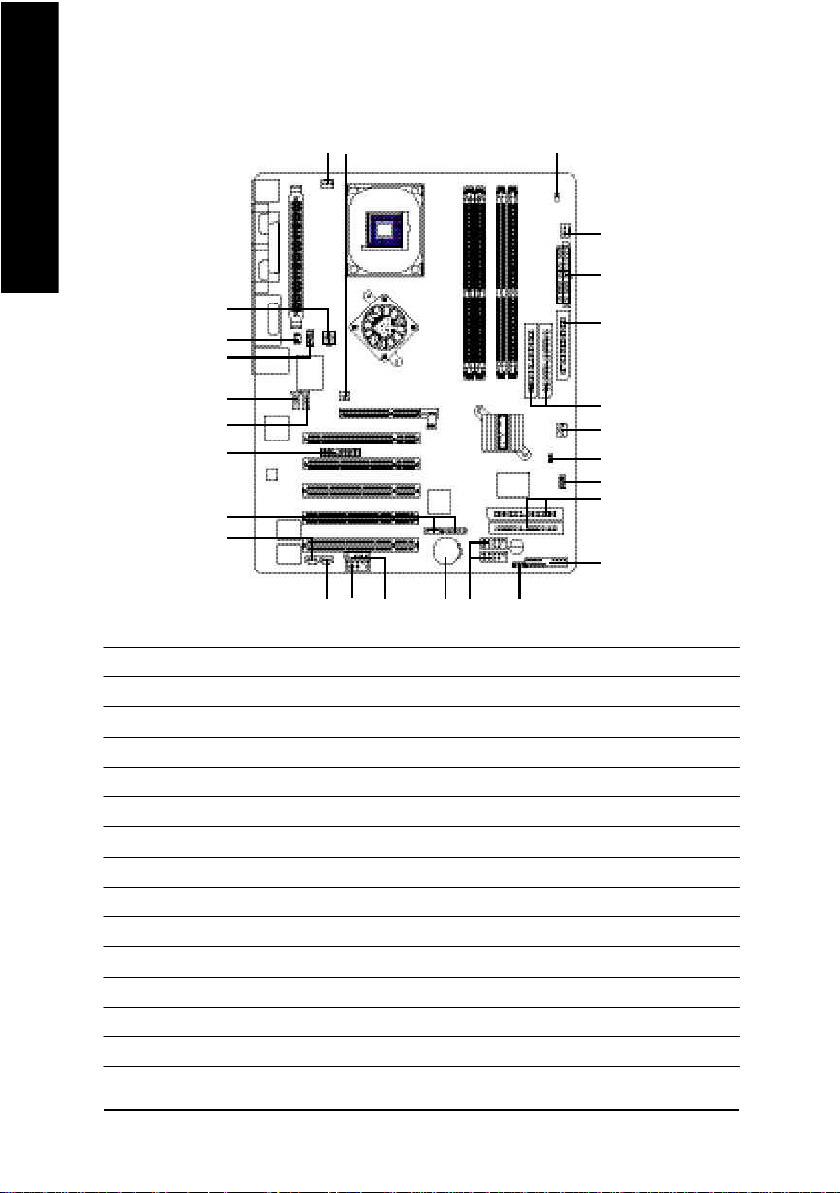
GA-SINXP1394 主機板 Layout 圖
中
文
KB_M S
COMA
COMB
LINE_OUT
LINE_IN
MIC_IN
USB_LAN
Inte l
KENAI 32
CODEC
LPT
GAME
CD _IN
Back up
BIOS
Ma in
BIOS
CPU_FAN
VRM_CON N
SUR_C EN
ATX_12 V
F_AU DIO
IT8705F
AUX_IN
NB_FAN
1 39 4
AGP 8X DDR 400
P4 Titan
SPDIF_O
SPDIF_IN
SOC KET4 78
IR
SMB_CONN
SiS 6 55
PCI3
PCI5
GA-SINXP1394
AGP
PCI1
PCI2
Silicon Ima ge
SiI3 112A
PCI4
S_ ATA2 S_ ATA1
BAT
F_U SB2
DDR4
IDE4
IDE3
DDR3
SiS 9 63
F_U SB1
DDR1
DDR2
GigaRAID
IT8212F
PWR_ LED
PWR_FAN
IDE2
SYS _FAN
BUZZER
LED
ATX
IDE1
FD D
CI
WOL
F_PANEL
- 8 -GA-S INXP1394 主機板
Page 13
第二章 硬體安裝步驟
繁
請依據下列方式,完成電腦的安裝:
步驟 1 - 安裝中央處理器 (CPU)
步驟 2 - 安裝記憶體模組
步驟 3 - 安裝所有介面卡
步驟 4 - 連接所有訊號線、排線、電源供應線及面板控制線
步驟 5 - 完成 BIOS 組態設定
步驟 6 - 安裝軟體驅動程式
步驟 4
步驟 4
步驟 1
步驟 2
體
中
文
步驟 4
步驟 3
- 9 - 硬體安裝步驟
Page 14
繁
步驟1:安裝中央處理器(CPU)
體
中
文
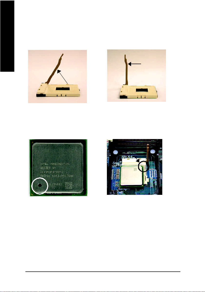
步驟1-1:中央處理器之安裝
連桿拉至
約 65 度角
1. 將處理器插座連桿向上拉起至
約65度,連桿有時會有卡住的
感覺,此時稍加用力繼續將連
桿拉至90度,並會有"喀"的聲
音。
第 1 腳
連桿
2. 將處理器插座連桿向上拉起至
90度角的位置。
第 1 腳
3. 中央處理器正面
M 請確認您使用的中央處理器為本主機板的支援範圍。
M 請注意CPU 的第一腳位置,若您插入的方向錯誤,處理器就無
法插入,請立刻更改插入方向。
4. 將處理器的第一腳(金色三腳記號
處)對準插座上的缺腳記號再將處
理器插入插座。處理器插入定位
後再將連桿向下按至原位。
- 10 -GA-S INXP1394 主機板
Page 15

步驟1-2:中央處理器之散熱裝置安裝
繁
體
中
文
1. 先將CPU散熱風扇一邊的
卡榫以平均施力的方式往
下壓,直至扣緊為止;以同
樣地方式再將另一邊卡榫扣
緊。
M 請使用經Intel 認證過的散熱風扇。
M CPU 與風扇之間建議黏上散熱膠帶以增強散熱效果。
(當塗抹在 CPU 上的散熱膏呈現硬化的現象時,可能會產生
散熱風扇黏住 CPU 的情況,在此情況下如果您想移除散熱風
扇將會有損毀 CPU 的可能。為避免此情況發生,我們建議您
可使用散熱膠帶來取代散熱膏,或是小心地移除散熱風
扇。)
M 依您實際所使用的散熱風扇,以正確方向將風扇確實扣緊。
M 確認CPU 散熱風扇電源線接至 CPU_FAN 接頭,完成安裝。
(詳細安裝步驟請參考散熱風扇的使用手冊。)
2. 將CPU散熱風扇的電源線
插入主機板上的”CPU散
熱風扇電源插座”。
- 11 - 硬體安裝步驟
Page 16

繁
步驟2 :安裝記憶體模組
體
中
文
此主機板有4個(DIMM)擴充槽,BIOS會自動偵測記憶體的規格及其大小。安裝
記憶體只需將DIMM插入其插槽內即可,由於記憶體模組有一個凹痕,所以只能以
一個方向插入。在不同的插槽,記憶體大小可以不同。確認您所購買的記憶體模組
適用本主機板所支援的規格。
DDR
1. 記憶體模組有一個凹痕,所以只能以一個方
向插入。
2. 扳開記憶體模組插槽卡榫,以平均施力
的方式,將記憶體模組下壓推入插座。
記憶體模組插入定位後,將卡榫向內按
至卡住。
3. 將卡榫向內推,確實卡住記憶體模組
DIMM。一旦固定位置,兩旁的卡榫便
自動卡住記憶體模組予以固定。試著輕
輕搖動記憶體模組,若不搖晃則裝置成
功。
M 當LED記憶體指示燈在亮的狀態時,請勿插拔記憶體模組。
M 記憶體模組設計有防呆標示,若您插入的方向錯誤,記憶體模
組就無法插入,請立刻更改插入方向。
DDR 功能介紹
DDR(Double Data Rate)是PC產業在SDRAM架構上的一項重要演進,利用雙倍的記
憶體頻寬可解決系統資料的瓶頸問題。建立在SDRAM的基礎架構設計之上,DDR
是一項高效能及低成本兼具的創新技術,能使記憶體廠商、OEM系統廠商在熟悉
的標準上建構新一代的電腦系統產品。
因為具有優良可行性、價格以及整體市場的支援性,DDR SDRAM將提供優良的
解決方式以及將現有的SDRAM轉換到DDR SDRAM的最佳路徑。
DDR可雙倍讀與寫的資料傳輸速率,利用最高可達2.664GB/s的傳輸速度,DDR能
使系統廠商建立一個高效能及低滯留時間的DRAM架構,適合在伺服器、工作站、
高階PC以及進階整合性電腦系統使用。相對於目前SDRAM的3.3 volts 高核心電壓,
DDR的2.5 volts超低核心電壓將使得DDR為小型規格的桌上電腦以及筆記型
電腦的最佳技術解決方案。
- 12 -GA-S INXP1394 主機板
Page 17
GA-SINXP1394 支援 Dual Channel Technology ,當啟動 Dual Channel Technology
時, Mem ory Bus 的頻寬會增加為原來的兩倍,最高可達 5.4GB/s 。
GA-SINXP1394 包含 4 個 DIMM 擴充槽,而每個 Channel 包含2 個DIMM 擴充槽,
分別為:
Channel A:DIMM 1,DIMM 2
Channel B:DIMM 3,DIMM 4
由於 SiS®晶片組的限制,若要啟動Dual Channel Technology ,在安裝記憶體模
組時需注意以下安裝說明:
1. 如果您只安裝一支 DDR 記憶體模組,將無法啟動 Dual Channel Technology 。
2. 如果是安裝二支 DDR 記憶體模組(一樣的 Mem ory size 及顆粒大小),要分
別安裝在Channel A與Channel B,才可以啟動Dual Channel Technology;二支DDR
記憶體模組如果安裝在同一個 Channel ,將無法啟動 Dua l Channel Technolo gy 。
而 DDR 記憶體模組其中一支一定要安裝在Channel A 或B 才可以開機,要安裝
在DIMM 1、DIM M 2、DIM M 3或DIMM 4即可。
3. 如果是安裝三支 DDR 記憶體模組,要使用相同的Mem ory size 及顆粒大小的
記憶體模組才可以啟動 Dual Channel Technology 。
4. 如果是安裝四支 DDR 記憶體模組,要使用相同的Mem ory size 及顆粒大小的
記憶體模組才可以啟動 Dual Channel Technology 。
在此建議如果您要安裝二支DDR記憶體,請分別安裝在相同顏色的記憶體插槽上,
即可啟動Dual Channel Technology。
所有的記憶體設定組態如以下二表:(注意:不在表中的組態即代表不開機)
l 表一:可啟動Dual Channel Technology(SS:單面,DS:雙面)
DIMM 1 DIMM 2 DIMM 3 DIMM 4
2 memory modules
3 memory modules
4 memory modules
DS/SS X DS/SS X
DS/SS X X DS/SS
X DS/SS DS/SS X
X DS/SS X DS/SS
DS/SS DS/SS DS/SS X
DS/SS DS/SS X DS/SS
DS/SS X DS/SS DS/SS
X DS/SS DS/SS DS/SS
DS/SS DS/SS DS/SS DS/SS
繁
體
中
文
- 13 - 硬體安裝步驟
Page 18
繁
體
中
文
l 表二:不啟動Dual Channel Technology(SS:單面,DS:雙面)
DIMM 1 DIMM 2 DIMM 3 DIMM 4
1 me mory module
2 me mory modules
DS/SS X X X
X DS/SS X X
X X DS/SS X
X X X DS/SS
DS/SS DS/SS X X
X X DS/SS DS/SS
步驟3 :安裝介面卡
步驟3-1:AGP卡之安裝
1. 在安裝介面卡之前請先詳細閱讀介面卡之使用手冊並將您電腦的電源關掉。
2. 將您電腦外殼拆除,並且讓自己保持接地。(為了使人體不帶電,以防止靜電傷
害電腦設備)。
3. 鬆開螺絲,移開介面卡安裝擴充槽旁的金屬擋片。
4. 將介面卡小心且確實的插入在擴充槽中。
5. 請確定所有介面卡皆確實固定插在該擴充槽,並將螺絲鎖回。
6. 重新將電腦機殼蓋上。
7. 接上電源線,若有必要請至BIOS程式中設定介面卡之相關設定。
8. 安裝相關驅動程式。
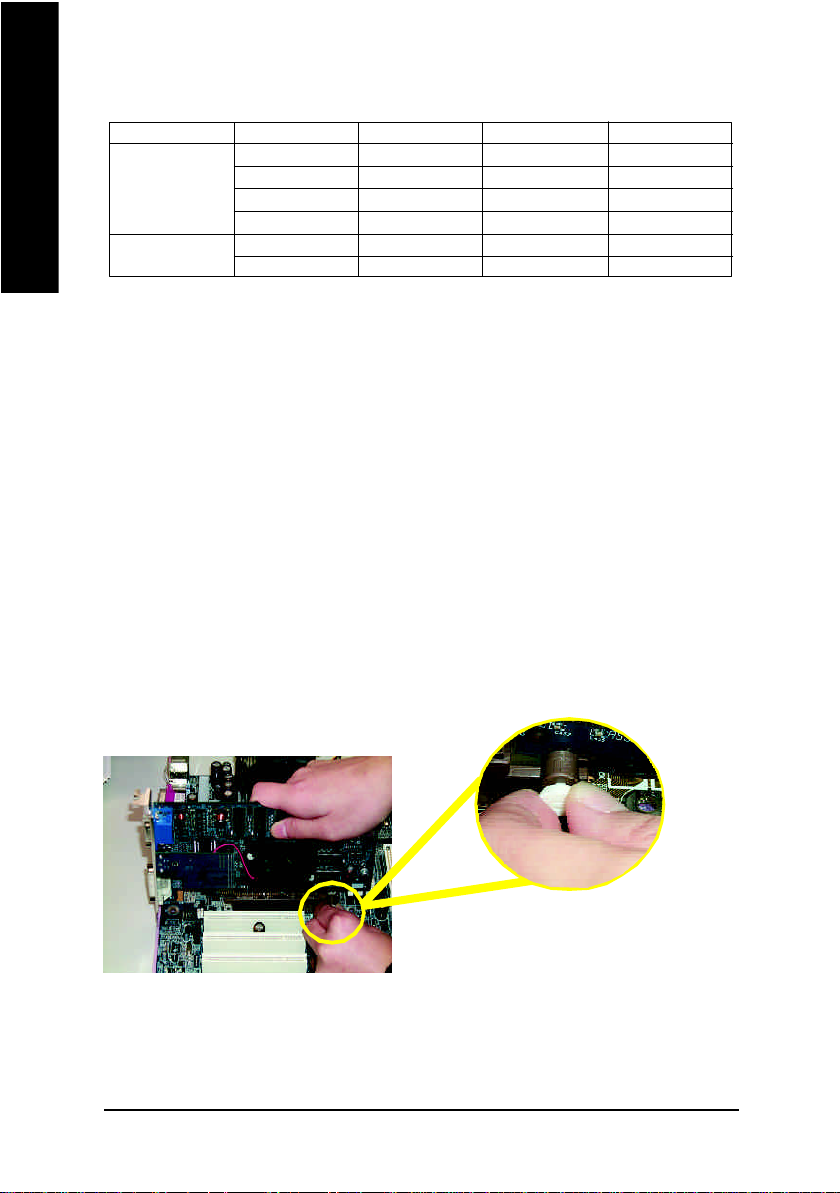
AGP 卡
當您要安裝/移除AGP卡時,請將白
色拉桿向外拉,再將AGP卡緩緩插入
AGP擴充槽中,放開拉桿 確實卡住
AGP 卡。
- 14 -GA-S INXP1394 主機板
Page 19
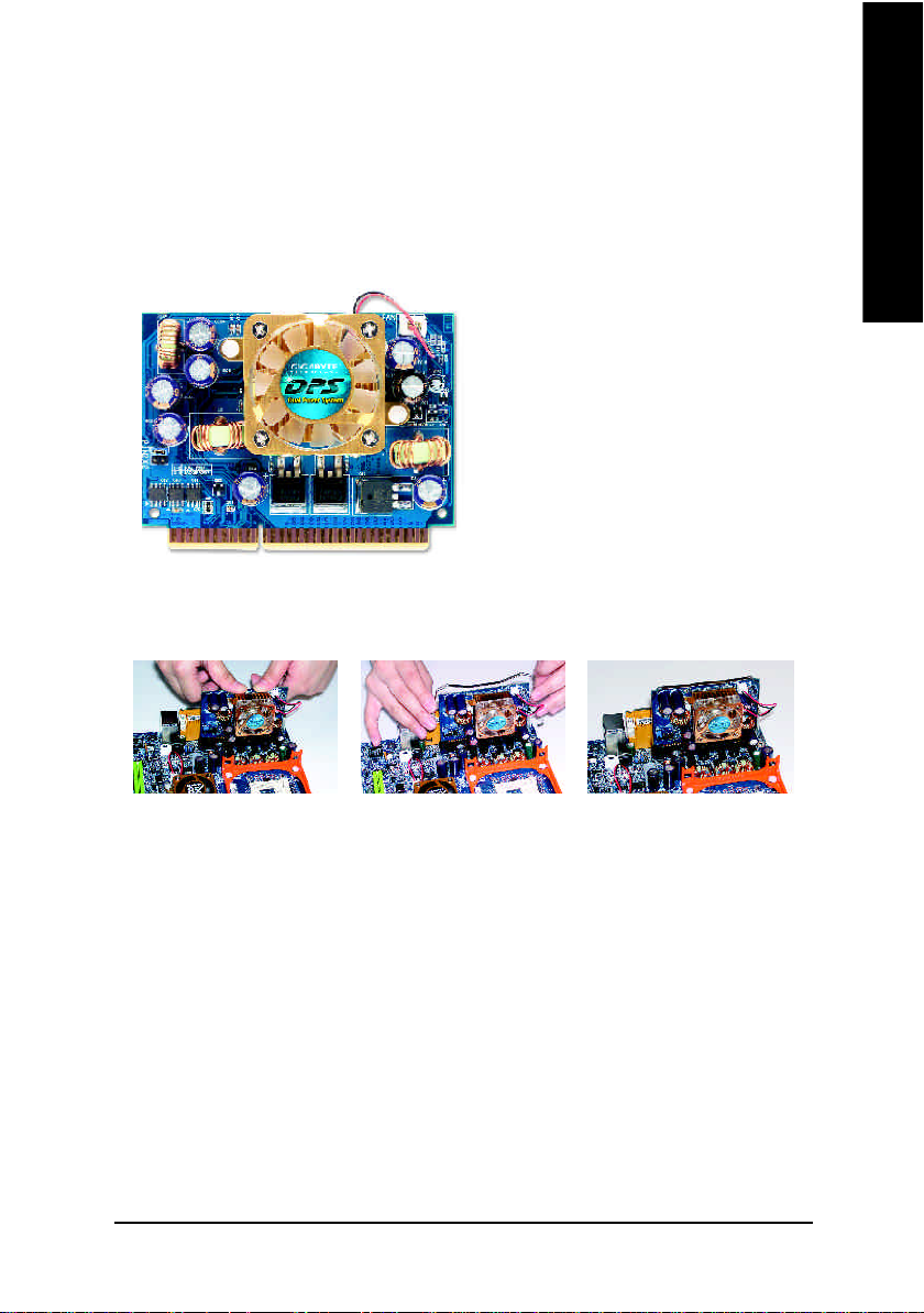
步驟3-2:DPVRM(Dual Power Voltage Regulator Module) 之安裝
繁
什麼是 DPVRM?
DPVRM (Dual Power Voltage Regulator Module)轉接卡是為了新一代的電腦而設計,DPVRM
能提供DPS(Dual Power System)雙迴路電源系統功能,意即DPVRM與主機板上的電
源能同時提供主機板一共六相電源,讓您的系統運作更為穩定。
Dual Power System(DPS)運作模式:
• Parallel Mode:
DPVRM與主機板的電源能同時運作而
產生六相電源,讓系統運作更為穩
定;若有何任一組電源損壞時,另一
組電源仍然可以提供電源給主機板,
讓系統繼續正常運作。
如何安裝DPVRM?
步驟 1 步驟 2 步驟 3
體
中
文
1. 主機板上的DPVRM插座有一個凹痕,所以只能以一個方向插入。
2. 將DPVRM垂直的下壓插入插座。
3. 再以附件中的扣具固定住DPVRM卡。
4. 若要拆下DPVRM,請以反向操作上述步驟。
- 15 - 硬體安裝步驟
Page 20
繁
步驟4:連接所有訊號線、排線、電源供應線及面
體
中
文
板控制線
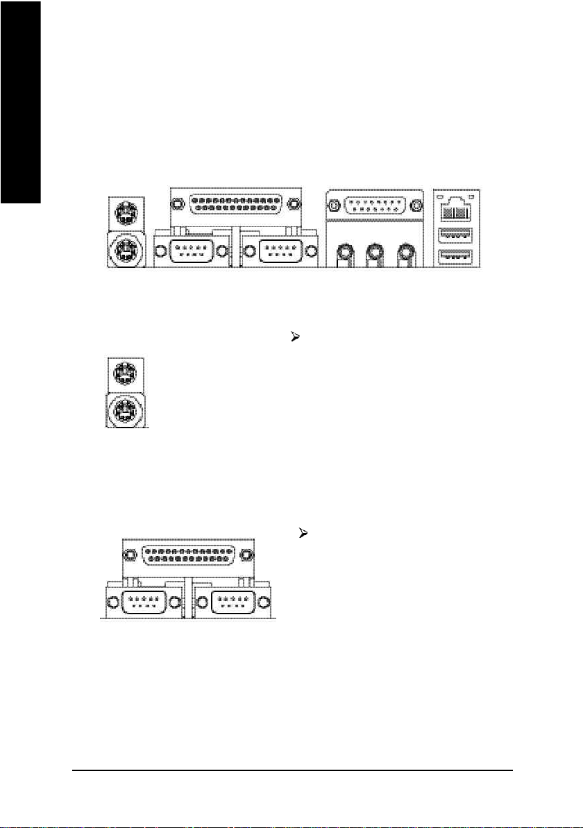
步驟4-1:後方I/O裝置鐵片介紹
u
u PS/2 鍵盤及 PS/2 滑鼠插座
v 串列埠 A/ 串列埠 B/ 印表機並列埠插座
串列埠A
v
PS/2 滑鼠插座
(6 pin Female)
PS/2 鍵盤插座
(6 pin Female)
並列埠插座
(25 pin Female)
串列埠B
串列埠 (9 pin Male)
本主機板提供標準PS/2鍵盤介面及
PS/2滑鼠介面插座。
本主機板支援兩組標準的串列埠傳輸
協定之週邊裝置,及一組標準的並列
傳輸協定之週邊裝置,您可以依據您
的需求連接您需要的裝置,如並列埠
有印表機,串列埠有滑鼠、數據機
等。
w
x
y
- 16 -GA-S INXP1394 主機板
Page 21
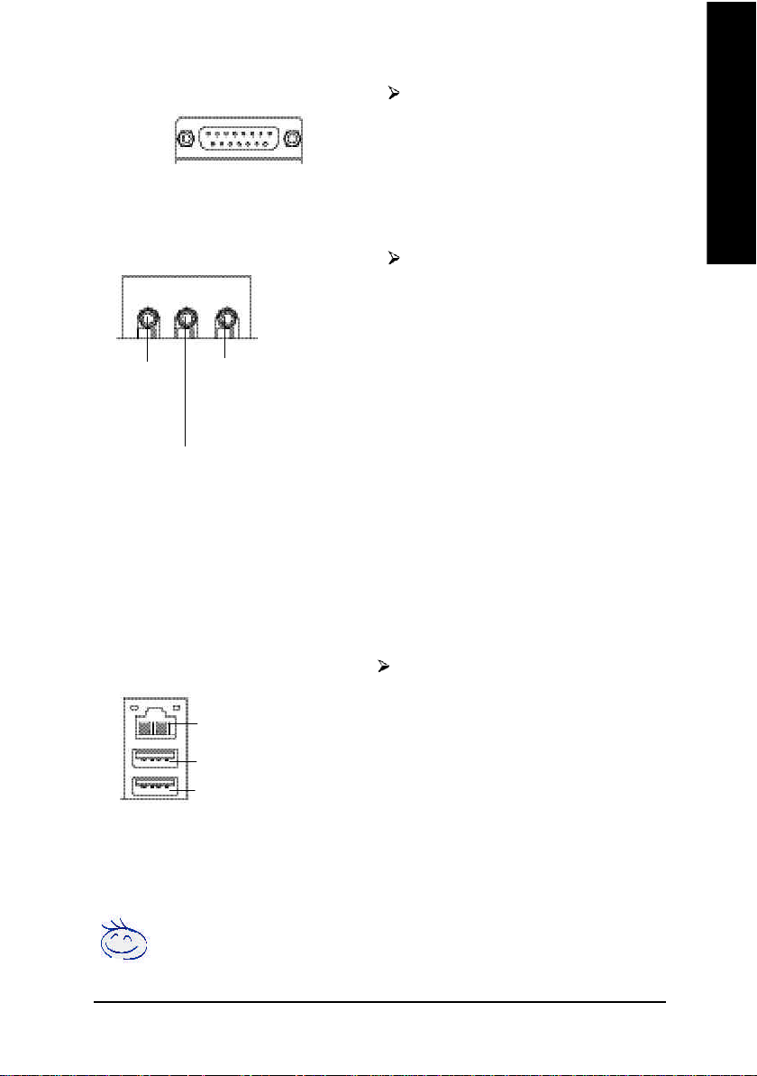
w 遊戲搖桿控制埠
遊戲搖桿控制埠
(15 pin Female)
本主機板支援標準的音效輸入接腳及
遊戲搖桿控制埠,您在設定完成內建
音效的驅動程式後,即可將喇叭輸出
接腳接在音源輸出端。
繁
體
中
文
x 音源插座
Line Out
(Front
Speaker)
(Rear Speaker)
MIC In
(Center and Subwoofer)
Line In
y 通用序列埠, 網路插座
LAN (網路插座)
USB 0 (通用序列埠 0)
USB 1 (通用序列埠 1)
麥克風接腳可接在麥克風輸入端,至
於音源輸入端可以接上如:光碟機,
隨身聽及其他音源輸入接腳。您可以
藉由音效軟體去選擇使用2-/4-/6-聲道
音效功能,假如你要啟動6-channel功
能,請先將音效軟體設妥,以下有2
種硬體接法提供你選擇。
方法一:
直接將前端喇叭接至”Line Out”音源
插座,再將後端喇叭接至”Line In”音
源插座,最後將中央重低音喇叭接至”
Mic In”音源插座。
方法二:
你可以參考第23頁,並聯絡相關代理
商購買SUR_CEN連接排線套件。
當你要使用通用串列埠連接埠時,必須
先確認您要使用的週邊裝置為標準的
USB介面,如:USB鍵盤,滑鼠,USB
掃瞄器,USB ZIP,USB 喇叭等….而且
您也必須確認您的作業系統是否有支援
此功能,或是需要另外再掛其他的驅動
程式,如此才能正常工作,詳情請參考
USB週邊裝置的使用手冊。
若您需要更細部的2-/4-/6- 聲道設定手冊,請參考第 82 頁。
- 17 - 硬體安裝步驟
Page 22
繁
步驟4-2:插座及跳線介紹
體
中
文
1
4
5
16
15
17
18
23
10
20
22
24
19
2114
11
12
1) CPU_FAN 15) F_AUDIO
2) PWR_FAN 16) SUR_CEN
3) SYS_FAN 17) CD_IN
4) NB_FAN 18) AUX_IN
5) ATX_12V 19) SPDIF_O
6) ATX 20) SPDIF_IN
7) FDD 21) F_USB1/F_USB2
8) IDE1/IDE2 22) SMB_CONN
9) IDE3/IDE4 23) 1394
10) S_ATA1/S_ATA2 24) IR
11) LED 25) CI
12) PWR_LED 26) WOL
13) F_PANEL
14) BAT
2
6
7
8
3
25
26
9
13
- 18 -GA-S INXP1394 主機板
Page 23
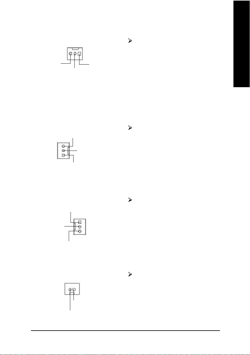
1) CPU_FAN (CPU 散熱風扇電源插座)
1
訊號腳
+12V
接地腳
2) PWR_FAN (電源散熱風扇電源插座)
訊號腳
1
+12V
接地腳
3) SYS_FAN (系統散熱風扇電源插座)
接地腳
+12V
1
請特別注意,當我們安裝處理器時要
特別注意將散熱風扇安裝妥當,不然
您的處理器將處於不正常的工作環
境,甚至會因為溫度過高,而燒毀處
理器。此CPU散熱風扇電源插座,提
供最大電流為600毫安培。
請特別注意,一般我們建議ATX的主
機板,至少安裝一台電源散熱風扇,
因為可以增加機殼內部散熱的速度進
而減低機殼內的工作溫度。
請特別注意,當有些AGP或PCI卡有
散熱風扇接腳,我們即可以利用系統
散熱風扇接腳,來協助相關裝置散
熱。
繁
體
中
文
訊號腳
4)NB_FAN (北橋晶片風扇接腳)
1
+12V
接地腳
請特別注意,如果安裝方法錯誤將使
北橋晶片風扇無法運作,也有可能造
成系統不穩,或者其它不可預期之結
果。
- 19 - 硬體安裝步驟
Page 24
繁
體
中
文
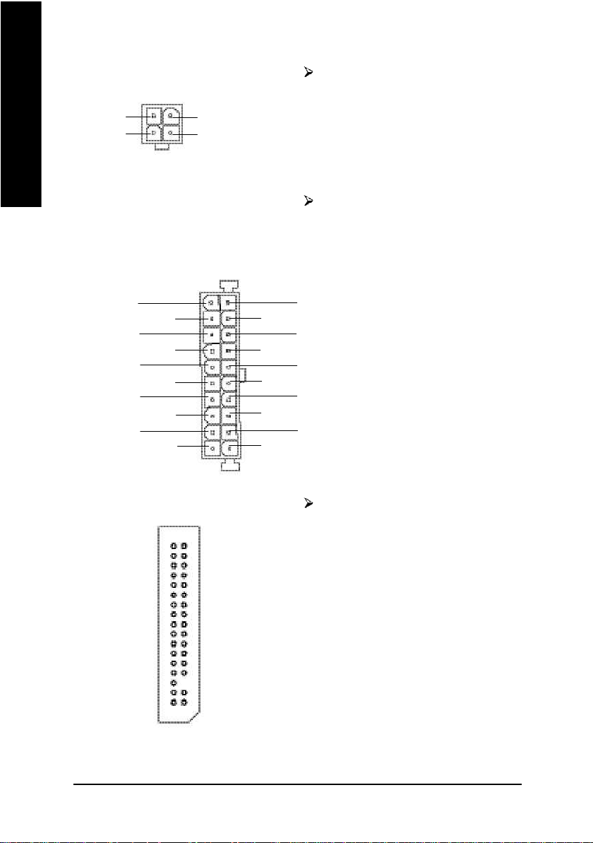
5) ATX_12V (+12V電源插座)
2
1
接地腳
4
接地腳
+12V+12V
3
請特別注意,此ATX_12V 電源插座為
提供CPU電源使用。若沒有插上
ATX_12V電源插座,系統將不會啟
動。
6) ATX_POWER (ATX電源插座)
20
+12V
5V SB (Stand by +5V)
電源良好
接地腳
VC C
接地腳
VC C
接地腳
3.3V
3.3V
1
7) FDD (軟碟機插座)
請特別注意,先將AC 交流電(110/220V)
拔除,再將ATX電源插頭緊密的插入
主機板的ATX電源插座,並接好其相
關配備才可以將AC交流電(110/220V)插
入交流電源插座。
VC C
VC C
-5V
接地腳
接地腳
接地腳
PS-ON(Soft On/Off)
接地腳
-12V
3.3V
請特別注意,這個插座用來連接軟式
磁碟機的排線,而排線的另一端可以
連接一部軟式磁碟機。通常排線的第
1Pin會以紅色表示,請連接至插座的
Pin1位置。
1
- 20 -GA-S INXP1394 主機板
Page 25
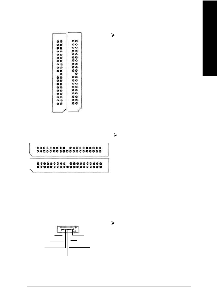
8) IDE1/ IDE2 (第一組及第二組 IDE 插座)
請特別注意:
請將您的第一顆硬碟連接第一組 IDE
插座,光碟機接至第二組 IDE插座。
繁
體
中
文
第二組 IDE插座
1
第一組 IDE插座
1
9)IDE3 / IDE4 Connector (RAID 及 ATA-133 插座,綠色插座)
第四組 IDE插座
1
1
第三組 IDE插座
請特別注意:
1. 請將您的第一顆硬碟連接第一組 IDE
插座,光碟機接至第二組 IDE插
座。
2. 如果您要使用 IDE3及IDE4時,請配
合BIOS做RAID或ATA133功能選擇,
並且請安裝適當的驅動程式,方可
正常動作。詳細請參考ITE RAID 使用
手冊。
10) S_ATA1/S_ATA2 (Serial ATA插座)
Serial ATA插座提供每秒150MB的傳輸
接地腳
RXN
RXP
17
接地腳
TXP
TXN
接地腳
速度,請配合BIOS 做 Serial ATA RAID
設定。並且請安裝適當的驅動程式,
方可正常動作。詳細請參考Serial ATA
RAID使用手冊。
- 21 - 硬體安裝步驟
Page 26

繁
體
中
文
11) LED
請特別注意,當記憶體電源指示燈
-
+
亮起時,千萬不可以插拔記憶體裝
置,因為記憶體插槽內還有2.5V待
機電源,可能會導致短路或者其他
不可預知的問題,請將系統關機後再
做記憶體插拔的動作。
12) PWR_LED
1
MPD+
MPD-
MPD-
請特別注意,此PWR_LED是連接系統
電源指示燈。指示系統處於ON或
OFF,當Power LED在Suspend模式下,
會以閃爍的方式呈現。如果您使用的
是雙顏色的power LED,LED會變顏
色。
13) F_PANEL (前端控制面板)
MSG+
1
2
1
1 19
HD+
HD (IDE Hard Disk Active LED) Pin 1: LED anode(+)硬碟指示燈正極
硬碟動作指示燈 Pin 2: LED cathode(-)硬碟指示燈負極
(藍色) M請注意正負極性
SPK (Speaker Connector)喇叭接腳 Pin 1: VCC(+) +5v 電源接腳
(橘色) Pin 2- Pin 3: NC 空腳
RES (Reset Switch)系統重置開關 Open: Normal Operation 一般運作
(綠色) Close: Reset Hardware System
PW (Soft Power Connector) Open: Normal Operation 開路:一般運作
按鍵開關機 Close: Power On/Off 短路:開機/關機
(紅色) M無正負極性正反皆可使用
MSG (Message LED/Power/ Pin 1: LED anode(+)省電指示燈正極
Sleep LED) Pin 2: LED cathode(-)省電指示燈負極
(黃色) M請注意正負極性
NC(紫色) 無作用
PW+
MSG-
HD-
1
RES-
PW-
1
RES+
SPK+
1
NC
Pin 4: Data(-) 訊號接腳
強迫系統重置開機
M無正負極性正反皆可使用
SPK-
20
請特別注意,當您購買電腦機殼時,電腦機殼的控制面板有電源指示燈,喇
叭,系統重置開關,電源開關等,你可以依據上列表格的定義加上連接。
- 22 -GA-S INXP1394 主機板
Page 27
14) BAT (電池)
警告
如果電池有任何不正確的移除動
作,將會產生危險。
如果需要更換電池時請更換相同廠
+
牌、型號的電池。
有關電池規格及注意事項請參考電
池廠商之介紹。
若您要清除CMOS內的資料...
1. 請先將電腦關機並拔除電源插座。
2. 將電池從主機板拆下並等待30秒。
3. 再將電池重新裝好。
4. 接上電源,即可開機。
繁
體
中
文
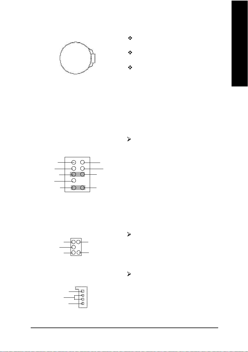
15) F_AUDIO (第二組音源插座)
2101
MIC
REF
Front Audio (R)
Reserved
Front Audio (L)
9
接地腳
電源
Rear Audio (R)
Rear Audio (L)
請特別注意,當您購買電腦機殼時,
可以選購音效接腳是設計在電腦機殼
的前面面板上,此時就可以使用第二
組音源接腳,如果有任何問題可就近
向經銷商詢問相關問題。注意:若您要
使用第二組音源接腳,請移除
Pin5-6,Pin9-10的Jumper。
請注意,前方音源插座與後方音源插
座只能擇一使用。
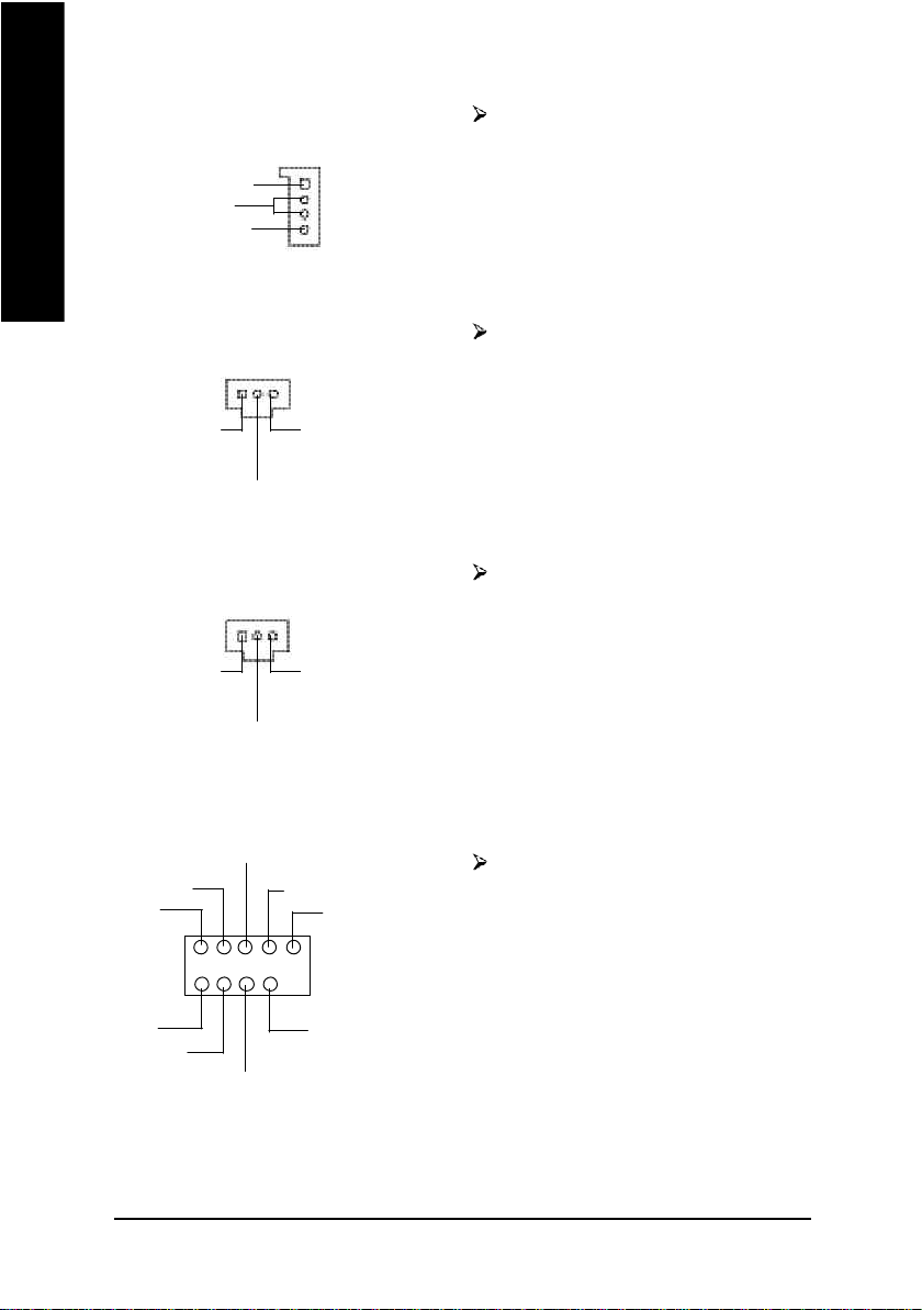
16) SUR_CEN(中置聲道模組擴充插座)
請特別注意,你可以參考左側接腳定
義,並聯絡相關代理商購買SUR_CEN
連接排線套件。
SUR OUTL
GND
CENTER_OUT
1
SUR OUTR
BASS_OUT
17) CD_IN (光碟機音源插座) 光碟機音源插座:將CD-ROM或
DVD-ROM的CD音源連接至此主機板
左聲道音源輸入
接地腳
右聲道音源輸入
1
內建音效卡中。
- 23 - 硬體安裝步驟
Page 28
繁
體
中
文
18) AUX_IN (外接音源輔助插座)
左聲道音源輸入
接地腳
右聲道音源輸入
1
外接音源輔助插座:將電視協調器或
MPEG解壓縮卡的音源連接至主機板
內建音效卡中。
19) SPDIF_O (SPDIF)
1
VC C
數位音效輸出腳
20) SPDIF_IN
1
VC C
數位音效輸入腳
接地腳
接地腳
Sony/Philip Digital Interface Format為新力/
飛利浦所制定的數位介面格式,
SPDIF輸出能夠提供數位音效給外接
的喇叭或者第三代音效編碼格式(AC-3)
解壓縮成杜比數位格式。請特別注
意,使用此功能時,須確認您的音響
系統具有數位輸入(SPDIF In)功能。
Sony/Philip Digital Interface Format為新力/
飛利浦所制定的數位介面格式,
SPDIF IN能將數位訊號透過應用程式
輸入至電腦中處理。請特別注意,使
用此功能時,須確認您的周邊裝置具
有數位輸出(SPDIF Out)功能。
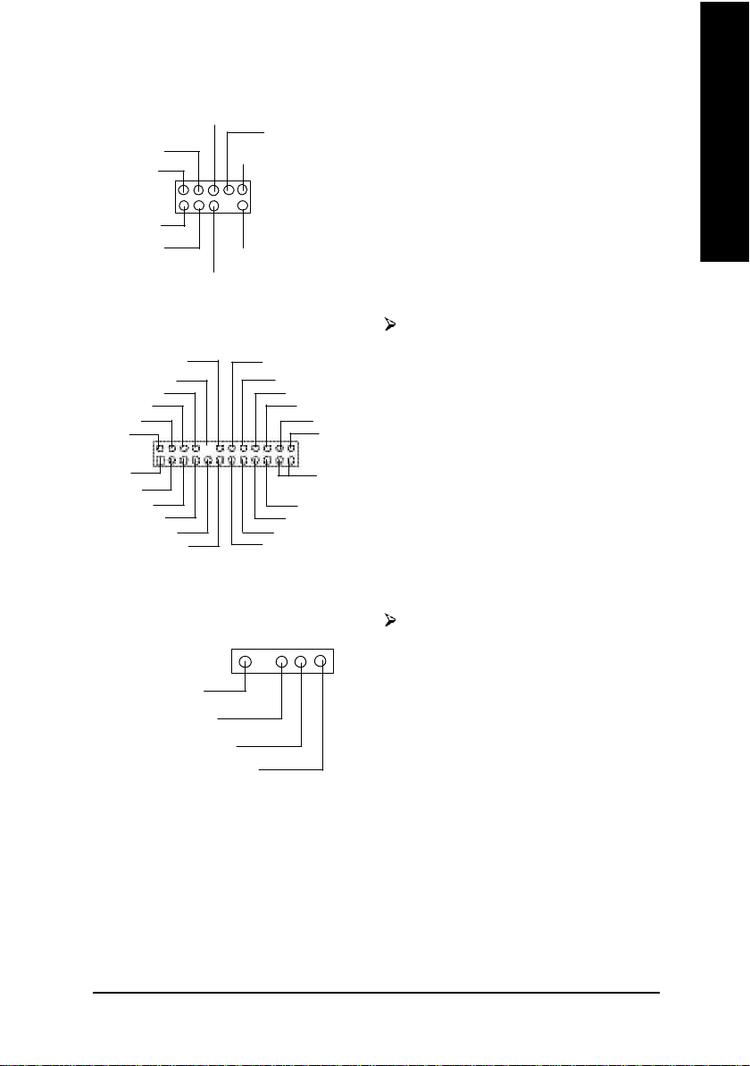
21) F_USB1/F_USB2 (前端通用串列埠插座)
USB Dy-
電源
USB Dy+
接地腳
無作用
1
請特別注意,前端USB接腳是有方向
性的,所以安裝USB裝置時,要特別
注意極性,而且前端USB連接排線為
選擇性的功能套件,可以聯絡相關代
理商購買。
電源
USB Dx-
接地腳
USB Dx+
- 24 -GA-S INXP1394 主機板
Page 29
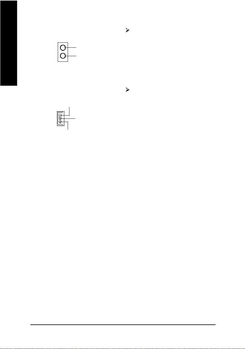
22) SMB_CONN
GP IO
VC C
接地腳
+12V
無作用
繁
體
中
1
SMBCLK
SMBDATA
+12V
接地腳
23) 1394 (IEEE1394 Connector)
LINKON
接地腳
+12V
+12V
接地腳
LREQ
CTL1
N C
D0
1
LPS
D4
CTL0
D2
D5
D1
SYSC LK
D6
接地腳
D3
D7
24) IR (紅外線插座)
1
VCC(+5V)
紅外線接收腳
接地腳
紅外線傳輸腳
接地腳
3VDUAL
3VDUAL
文
電子電機工程師協會
1394標準協定連接埠
IEEE1394:
為(Insitute of Electrical Eletronics Engineers)電
子電機工程師協會所制定的串列匯流排
介面標準具有高速、高頻寬及熱熱插拔
功能。
請特別注意,紅外線接腳是有方向性
的,所以在安裝紅外線裝置時,要特
別注意極性,而且紅外線裝置為選擇
性的功能套件,可以聯絡相關代理商
購買。
- 25 - 硬體安裝步驟
Page 30
繁
體
中
文
25) CI (電腦機殼被開啟偵測)
1
訊號腳
接地腳
本主機板提供電腦機殼被開啟偵測功
能,當您要使用此功能需搭配外接式
偵測裝置。
26) WOL(網路卡喚醒功能插座)
+5V SB
1
接地腳
訊號腳
主要是透過區域網路傳輸。若要使用
LAN喚醒功能,您的網卡上的晶片組
必須支援此功能,並使用排線連接
LAN卡和主機板上的WOL接腳。
- 26 -GA-S INXP1394 主機板
Page 31

繁
體
中
文
- 27 - 硬體安裝步驟
Page 32

繁
體
中
文
- 28 -GA-S INXP1394 主機板
Page 33

第三章 BIOS 組態設定
繁
基本上主機板所附Award BIOS 便包含了CMOS S ETUP 程式,以供使用者自行依照
需求,設定不同的數據,使電腦正常工作,或執行特定的功能。
CMOS SETUP會將各項數據儲存於主機板上內建的 CMOS SRAM中,當電源關閉時,
則由主機板上的鋰電池繼續供應CM OS SRAM 所需電力。
當電源開啟之後,BIOS 開始進行POST(Power On Self Test開機自我測試)時,按
下<Del >鍵便可進入Award BIOS 的CM OS S ETU P主畫面中。如果您需要進階的
BIOS 設定,當您在BIOS 設定畫面時按下“Ctrl+F1”即可進入。
操作按鍵說明
h 移到上一個項目
i 移到下一個項目
f 移到左邊的項目
g 移到右邊的項目
Enter 確定選項
Esc 回到主畫面,或從主畫面中結束SETUP 程式
Page Up 改變設定狀態,或增加欄位中之數值內容
Page Down 改變設定狀態,或減少欄位中之數值內容
F1 顯示所有功能鍵的相關說明
F2 可顯示目前設定項目的相關說明
F3 功能保留
F4 功能保留
F5 可載入該畫面原先所有項目設定(但不適用主畫面)
F6 可載入該畫面之Fail-Safe 預設設定(但不適用主畫面)
F7 可載入該畫面之Optimized 預設設定(但不適用主畫面)
F8 Dual BIOS/Q-Flash 功能
F9 系統資訊
F10 儲存設定並離開CM OS SETUP 程式
體
中
文
BIOS 組態設定- 29 -
Page 34

繁
體
中
文
如何使用輔助說明
主畫面的輔助說明
當您在SETUP 主畫面時,隨著選項的移動,底下便跟著顯示︰目前被選到的
SETUP 項目的主要設定內容。
設定畫面的輔助說明
當您在設定各個欄位的內容時,只要按下<F1 >,便可得到該欄位的設定預設值
及所有可以的設定值,如BIOS預設值或C M OS SETUP 預設值,若欲跳離輔助說明
視窗,只須按<Esc>鍵即可。
主畫面功能(BIOS 範例版本:F1)
當您進入CM OS SETUP 設定畫面時,便可看到如下之主畫面,從主畫面中可以讓你
選擇各種不同之設定選單,你可以用上下左右鍵來選擇你要設定之選項並按 Enter進
入子選單。
CMOS Setup Utility-Copy right (C) 1984-2002 Award Software
}Standard CMOS Features Top Performance
}Advanced BIOS Features Load Fail-Safe Defaults
}Integrated Peripherals Load Optimized Defaults
}Power Management Setup Set Supervisor Password
}PnP/PCI Configurations Set User Password
}PC Health Status Save & Exit Setup
}Frequency/Voltage Control Exit Without Saving
ESC:Quit higf:Select Item
F8: F8: Dual BIOS/Q-Flash F10:Save & Exit Setup
Time, Date, Hard Disk Ty pe...
圖 1: 主畫面功能
若在主畫面功能選項中,沒有找到您所需要的選項設定,請按
“Ctrl+F1”進入進階BIOS 畫面設定,作進一步搜尋。
l Stand ard CMOS Features (標準 CMOS 設定)
設定日期、時間、軟硬碟規格、及顯示器種類。
- 30 -GA-SINX P1394 主機板
Page 35

l Ad vanced BIOS Features (進階 BIOS 功能設定)
設定BIOS提供的特殊功能,例如病毒警告、開機磁碟優先順序、磁碟代號交
換....等。
l Integrated Peripher als (整合週邊設定)
在此設定畫面包括所有週邊設備的的設定。如COM Port 使用的IRQ 位址,LPT
Port 使用的模式SPP、EPP 或ECP 以及IDE 介面使用何種DMA Mode...等。
l Pow er Management Setup (省電功能設定)
設定CPU 、硬碟、 GREEN 螢幕等裝置的省電功能運作方式。
l PnP/PCI Confi guration (隨插即用與 PCI組態設定)
設定ISA 之PnP 即插即用介面以及PCI 介面的相關參數。
l PC H ealth Status (電腦健康狀態)
系統自動偵測電壓,溫度及風扇轉速等。
l Frequency/Voltage Control (頻率 / 電壓控制)
設定控制CPU 時脈及倍頻調整。
l Top Performance (最高效能)
如果您想使您的系統獲得最高效能,請將"Top Performance" 設定為 "Enabled" 。
l Load Fail-Safe Defaults (載入 Fai l-Safe預設值)
執行此功能可載入BIOS的CMOS設定預設值,此設定是比較保守,但較能進
入開機狀態的設定值。
l Load Optimized Defaults (載入 Optimized預設值)
執行此功能可載入Optimized的CMOS設定預設值,此設定是較能發揮主機板速
度的設定。
l Set Supervi sor Password (管理者的密碼)
設定一個密碼,並適用於進入系統或進入SETUP 修改CMOS 設定。
l Set U ser Pass w ord (使用者密碼)
設定一個密碼,並適用於開機使用PC 及進入BIOS 修改設定 。
l Save & Exit Setup (儲存並結束)
儲存所有設定結果並離開SETUP程式,此時BIOS會重新開機,以便使用新的
設定值,按<F10 >亦可執行本選項。
l Exit Without Saving (結束 SETU P程式)
不儲存修改結果,保持舊有設定重新開機,按<ESC>亦可直接執行本選項。
繁
體
中
文
BIOS 組態設定- 31 -
Page 36

繁
標準 CMOS 設定
體
中
文
CMOS Setup Utility-Copy right (C) 1984-2002 Award Software
Standard CMOS Features
Date (mm:dd:y y) Fri, May 3 2002 Item Help
Time (hh:mm:ss) 17:56:23 Menu Level u
Change the day, month,
}IDE Primary Master None year
}IDE Primary Slave None
}IDE Secondary Master None <Week>
}IDE Secondary Slave None Sun. to Sat.
Drive A 1.44M, 3.5 in. <Month>
Drive B None Jan. to Dec.
Floppy 3 Mode Support Disabled
<Day>
Halt On All, But Keyboard 1 to 31 (or maximum
allowed in the month)
Base Memory 640K
Extended Memory 130048K <Year>
Total Memory 131072K 1999 to 2098
higf: Move Enter:Select +/-/PU/PD:Value F10:Save ESC:Ex it F1:General Help
F5:Previous Values F6:Fail-Safe Defaults F7:Optimized Defaults
圖 2: 標準 CMOS 設定
Date(mm:dd:yy) (日期設定)
即設定電腦中的日期,格式為「星期,月/ 日/ 年」,各欄位設定範圍如下
表示:
8 星期 由目前設定的「月/ 日/ 年」自萬年曆公式推算出今天為星期幾,
此欄位無法自行修改。
8 月(mm) 1 到12 月。
8 日(dd) 1 到28/29/30/31 日,視月份而定。
8 年(yy ) 1999 到2098 年。
- 32 -GA-SINX P1394 主機板
Page 37

Time(hh:mm:ss) (時間設定)
即設定電腦中的時間是以24 小時為計算單位,格式為「時:分:秒」舉例而
言,下午一點表示方式為13 : 00 : 00 。當電腦關機後,RTC功能會繼續執行,並由
主機板的電池供應所需電力。
繁
體
中
IDE Primary Master (Slave) / IDE Secondary Master (Slave)
(第一組硬碟 / 第二組硬碟參數設定)
設定第一、二組IDE硬碟參數規格,設定方式有兩種,建議的是設定方式是採方式
1 ,但經常更換I D E 硬碟的使用者則可採方式2 ,省去每次換硬碟都要重新設定
CMOS 的麻煩。
方式1:設成User TYPE,自行輸入下列相關參數,即CYLS、HEADS、SECTORS、
MODE ,以便順利使用硬碟。
方式2:設定AU TO ,將 TYPE 及M ODE 皆設定AUTO,讓BIOS 在POST過程中,自
動測試IDE 裝置的各項參數直接採用。
8CYLS. Number of cylinders(磁柱的數量).
8HEADS Number of heads(磁頭的數量).
8PRECOMP Write precomp.
8LANDZONE Landing zone.
8SECTORS N umber of sectors(磁區的數量).
如果沒有裝設硬碟,請選擇"N ON E" 後按<Enter>
Drive A / Drive B (軟式磁碟機 A:/ B:種類設定)
可設定的項目如下表示:
8None 沒有安裝磁碟機。
8360K, 5.25 in. 5.25 吋磁碟機,360KB 容量。
81.2M, 5.25 in. 5.25 吋磁碟機,1.2MB 容量。
8720K, 3.5 in. 3 吋半磁碟機,720KB 容量。
81.44M, 3.5 in. 3 吋半磁碟機,1.44MB 容量。
82.88M, 3.5 in. 3 吋半磁碟機,2.88MB 容量。
文
Floppy 3 Mode Support (支援日本常用之 3 Mode 規格軟碟)
8Disabled 沒有安裝任何3 Mode 軟碟。
8Drive A A:安裝的是3 Mode 軟碟。
8Drive B B:安裝的是3 Mode 軟碟。
8Both A:與B:安裝的都是3 M ode 軟碟。
BIOS 組態設定- 33 -
Page 38

繁
體
中
文
H alt on(暫停選項設定)
當開機時,若POST偵測到異常,是否要提示,並等候處理?可選擇的項目
有:
8NO Errors 不管任何錯誤,均開機
8All Errors 有何錯誤均暫停等候處理
8All, But Keyboard 有何錯誤均暫停,等候處理,除了鍵盤以外
8All, But Diskette 有何錯誤均暫停,等候處理,除了軟碟以外
8All, But Disk/Key 有何錯誤均提示,等候處理,除了軟碟、鍵盤以外
M emory(記憶體容量顯示)
目前主機板所安裝的記憶體皆由BIOS 之POST(Pow er On Self Test)自動偵測,並顯示
於STANDARD CM OS SETUP 右下方。
Base Memory:傳統記憶體容量
PC 一般會保留640KB 容量做為 MS-DOS 作業系統的記憶體使用空間。
Extended Memory:延伸記憶體容量
可做為延伸記憶體的容量有多少,一般是總安裝容量扣除掉Base 及Other
Memory 之後的容量,如果數值不對,可能是有Module 沒安裝好,請仔細檢
查。
- 34 -GA-SINX P1394 主機板
Page 39

進階 BIOS 功能設定
CMOS Setup Utility-Copy right (C) 1984-2002 Award Software
Advanced BIOS Features
SATA/RAID/SCSI Boot Order [SCSI] Item Help
First Boot Device [Floppy ] Menu Lev el u
Second Boot Dev ice [HDD-0] Select onboard RAID or
Third Boot Dev ice [CDROM] PCI SCSI boot rom
Boot Up Floppy Seek [Disabled] order
Password Check [Setup]
# CPU Hyper-Threading [Disabled]
Flexible AGP 8X [Auto]
Init Display First [AGP]
higf: Move Enter:Select +/-/PU/PD:Value F10:Save ESC:Ex it F1:General Help
F5:Previous Values F6:Fail-Safe Defaults F7:Optimized Defaults
圖 3: 進階 BIOS 功能設定
繁
體
中
文
®
" # " 若您使用支援Hy per-Threading Technology 的 Intel
動偵測並顯示此選項。如果您將此選項設為Enabled ,那 "Power Management Setup" 以
及 "Integrated Peripherals" 內的 "USB Legacy Support" 將無法做任何設定。
Pentium
®
4 Processor ,系統將會自
SATA/RAID/SCSI Boot Order (選擇 RAID/SCSI 開機順序)
M 此功能允許您去選擇SATA/RAID/SC SI 的開機的順序
8SATA 由Serial ATA為第一優先的開機裝置。
8RAID 由 RAID 為第一優先的開機裝置。
8SCSI 由SC SI為第一優先的開機裝置。
BIOS 組態設定- 35 -
Page 40

繁
體
中
文
First / S econd / Third Boot Device (第一 /二 /三開機裝置)
M 這些功能允許您去設定開機設備的優先順序
8Floppy 由軟碟機為第一優先的開機裝置。
8LS120 由LS120 為第一優先的開機裝置。
8HDD-0~3 由硬碟機為第一優先的開機裝置。
8SCSI 由SCSI 裝置為第一優先的開機裝置。
8CDROM 由光碟機為第一優先的開機裝置。
8ZIP 由ZIP 為第一優先的開機裝置。
8USB-FDD 由U SB-FDD為第一優先的開機裝置。
8USB-ZIP 由U SB-ZIP 為第一優先的開機裝置。
8USB-CDROM 由USB-C DROM 為第一優先的開機裝置。
8USB-HDD 由USB-H DD 為第一優先的開機裝置。
8LAN 由LAN 為第一優先的開機裝置。
8Disabled 關閉此功能。
Boot Up Flopp y Seek(開機時測試軟碟)
設定在PC 開機時,POST 程式需不需要對FLOPPY 做一次SEEK 測試。
可設定的項目為:
8Enabled 要對 Floppy 做Seek 測試。
8Disabled 不必對Floppy 做Seek 測試。(預設值)
Passw ord Check(檢查密碼方式)
8System 無論是開機或進入CM OS SETUP 均要輸入密碼。
8Setup 只有在進入CMOS SETUP 時才要求輸入密碼。(預設值)
欲取消密碼之設定時,只要於SETUP 內重新設定密碼時,不要按任何鍵,直接
按<Enter >使密碼成為空白,即可取消密碼的設定。
C CPU Hyper-Thread ing
8Enabled 啟動 CPU Hy per Threading 功能,此功能只適用於支援多工處
理器模式的作業系統。
8Disabled 關閉此功能。(預設值)
- 36 -GA-SINX P1394 主機板
Page 41

Flexible AGP 8X
8Auto 自動根據AGP卡的穩定性及相容性來決定AGP的傳輸模式。
(預設值)
84X 不管AGP 卡是支援何種模式皆以4X模式啟動。
繁
體
中
Init Display First
8AGP 系統會從內建 AGP 顯示卡開機。(預設值)
8PCI 系統會從 PC I 顯示卡開機。
文
BIOS 組態設定- 37 -
Page 42

繁
整合週邊設定
體
中
文
CMOS Setup Utility-Copy right (C) 1984-2002 Award Software
Integrated Peripherals
IDE1 Conductor Cable [Auto] Item Help
IDE2 Conductor Cable [Auto] Menu Level u
On-Chip Primary PCI IDE [Enabled] [Auto]
On-Chip Secondary PCI IDE [Enabled] Auto-detect IDE
AC97 Audio [Enabled] cable type
USB Controller [Enabled]
USB Legacy Support [Disabled] [ATA66/100/133]
Onboard RAID dev ice [Enabled] Set Conductor cable
Onboard LAN device [Enabled] to ATA66/100/133(80-pins)
Onboard Serial ATA [Enabled]
Serial ATA Function [RAID] [ATA33]
Onboard Serial Port 1 [3F8/IRQ4] Set Conductor cable
Onboard Serial Port 2 [2F8/IRQ3] to ATA33(40-pins)
Onboard Parallel Port [378/IRQ7]
Parallel Port Mode [SPP]
x ECP Mode Use DMA 3
Game Port Address [201]
Midi Port Address [330]
Midi Port IRQ [10]
higf: Move Enter:Select +/-/PU/PD:Value F10:Save ESC:Ex it F1:General Help
F5:Previous Values F6:Fail-Safe Defaults F7:Optimized Defaults
圖 4: 整合週邊設定
IDE1 Conductor Cable
8Auto 設定為自動偵測。(預設值)
8ATA66/100/133 設定IDE1 排線為ATA66/100/133 (請確定您所使用的IDE裝置
及排線是否符合ATA66/100/133規格)。
8ATA33 設定IDE1 排線為ATA33 (請確定您所使用的IDE裝置及排線
是否符合ATA33規格)。
- 38 -GA-SINX P1394 主機板
Page 43

IDE2 Conductor Cable
8Auto 設定為自動偵測。(預設值)
8ATA66/100/133 設定IDE2 排線為ATA66/100/133 (請確定您所使用的IDE裝置
及排線是否符合ATA66/100/133規格)。
8ATA33 設定IDE2 排線為ATA33 (請確定您所使用的IDE裝置及排線
是否符合ATA33規格)。
On-Chip Primary IDE
(晶片組內建第一個 channel的 PCI IDE介面)
8Enabled 使用晶片組內建第一個channel 的IDE 介面。(預設值)
8Disabled 不使用。
On-Chi p Secondary IDE (晶片組內建第二個 channel的 IDE 介面)
主機板上晶片組所內建的Secondary IDE 介面是否使用。
8Enabled 使用晶片組內建第二個channel 的PCI IDE 介面。(預設值)
8Disabled 不使用。
AC97 Aud io
8Enabled 開啟 AC 97 Audio 。(預設值)
8Disabled 關閉 AC97 Audio。
繁
體
中
文
U SB Controller
8Enabled 開啟 USB C ontroller 。(預設值)
8Disabled 關閉 USB Controller 。
U SB Legacy Support (支援 USB 規格配備)
8Enabled 若您的作業系統沒有支援 USB 介面的週邊裝置,開啟此
功能可使其正常運作。
8Disabled 關閉此功能。(預設值)
Onb oard RAI D device
M 當您沒有接任何HD D 設備於IDE3/ 4 插座而此選項有啟動時,系統會出現以下
訊息”'MBUltra133 BIOS is not installed becasu e there are no drives attached'
will come out.' 您可以忽略此訊息或關閉此選項。
8Enabled 開啟內建 IDE 3/4 的 RAID 晶片功能 。(預設值)
8Disabled 關閉此功能。
BIOS 組態設定- 39 -
Page 44

繁
體
Onb oard LAN d evice (內建硬體 LAN)
8Enabled 開啟內建硬體 LAN 功能。(預設值)
8Disabled 關閉內建硬體LAN 功能。
中
文
Onb oard Serial ATA
如果您不想使用Serial ATA Controller的功能,您可以關閉此選項。
8Enabled 開啟內建Serial ATA Controller晶片功能。(預設值)
8Disabled 關閉此功能。
Serial ATA Function
8RAID 選擇內建Serial ATA 晶片的RAIID功能。(預設值)
8BASE 選擇內建Serial ATA 晶片的BASE 功能。
Onb oard Ser ial Port 1(內建串列插座介面 1)
8Auto 由BIOS 自動設定。
83F8/IRQ4 指定內建串列插座1 為COM 1且使用為3F8 位址。(預設值)
82F8/IRQ3 指定內建串列插座1 為COM 2且使用為2F8 位址。
83E8/IRQ4 指定內建串列插座1 為COM 3 且使用為3E8 位址。
82E8/IRQ3 指定內建串列插座1 為COM 4 且使用為2E8 位址。
8Disabled 關閉內建串列插座1 。
Onb oard Ser ial Port 2(內建串列插座介面 2)
8Auto 由BIOS 自動設定。
83F8/IRQ4 指定內建串列插座2 為COM 1且使用為3F8 位址。
82F8/IRQ3 指定內建串列插座2 為COM 2且使用為2F8 位址。(預設值)
83E8/IRQ4 指定內建串列插座2 為COM 3 且使用為3E8 位址。
82E8/IRQ3 指定內建串列插座2 為COM 4 且使用為2E8 位址。
8Disabled 關閉內建串列插座2 。
Onb oard Parallel p ort (內建並列插座)
8378/IRQ7 使用並指定內建並列插座位址為 378/IRQ7 。(預設值)
8278/IRQ5 使用並指定內建並列插座位址為 278/IRQ5 。
83BC/IRQ7 使用並指定內建並列插座位址為3BC/IRQ7 。
8Disabled 關閉內建的並列插座。
- 40 -GA-SINX P1394 主機板
Page 45

Parallel Port Mode (並列插座模式)
8SPP 使用一般的並列插座傳輸模式。(預設值)
8EPP 使用EPP(Enhanced Parallel Port)傳輸模式。
8ECP 使用ECP(Ex tended Capabilities Port)傳輸模式。
8ECP+EPP 同時支援EPP 及ECP 模式。
ECP M ode Use DMA
83 設定 EC P Mode use DMA 為3 。(預設值)
81 設定 ECP Mode use DMA 為1。
G ame Port Ad dress
8201 設定 Game Port Address 為 201。(預設值)
8209 設定Game Port Address 為 209。
8Disabled 關閉此功能。
M idi Port Address
8300 設定 Midi Port Address 為300 。
8330 設定M idi Port Address 為330。(預設值)
8Disabled 關閉此功能。
繁
體
中
文
M idi Port IRQ
85 設定 M idi Port IRQ 為5 。
810 設定Midi Port IRQ為10 。(預設值)
BIOS 組態設定- 41 -
Page 46

繁
體
中
文
省電功能設定
CMOS Setup Utility-Copy right (C) 1984-2002 Award Software
Power Management Setup
ACPI Suspend Type [S1(POS)] Item Help
Soft-Off by PWR_BTTN [Off] Menu Level u
System After AC Back [Off] [S1]
IRQ [3-7, 9-15], NMI [Enabled] Set suspend ty pe to
ModemRingOn [Enabled] Pow er On Suspend under
PME Event Wake Up [Enabled] ACPI OS
Power On by Keyboard [Disabled]
Power On by Mouse [Disabled] [S3]
Resume by Alarm [Disabled] Set suspend ty pe to
x Month Alarm NA Suspend to RAM under
x Day (of Month) 0 ACPI OS
x Time (hh:mm:ss) 0 0 0
Power LED in S1 state [Blinking]
higf: Move Enter:Select +/-/PU/PD:Value F10:Save ESC:Ex it F1:General Help
F5:Previous Values F6:Fail-Safe Defaults F7:Optimized Defaults
圖 5: 省電功能設定
ACPI Suspend Type
8S1(POS) 設定 ACPI Suspend type 為 S1 。(預設值)
8S3(STR) 設定 ACPI Suspend type 為 S3。
Soft-off b y PWR_BTTN (關機方式)
8Off 按一下 Soft-Off開關便直接關機。(預設值)
8Suspend 按一下Soft-Off開關便直接進入暫停模式。
System after AC Back (電源回復時的系統狀態)
8Last State 電源回復時,恢復系統斷電前狀態。
8Off 電源回復時,需按 PWR button 才能重新啟動系統。
(預設值)
8On 電源回復時,立刻啟動系統。
- 42 -GA-SINX P1394 主機板
Page 47

IRQ [3-7, 9-15], NM I
8Disabled 不使用此功能。
8Enabled 開啟此功能。(預設值)
繁
體
M odemRi ngOn (數據機開機)
8Disabled 不啟動數據機開機。
8Enabled 啟動數據機開機。(預設值)
PM E Event Wake Up (電源管理事件喚醒功能)
8Disabled 關閉電源管理事件喚醒功能。
8Enabled 啟動電源管理事件喚醒功能。(預設值)
Pow er On by Keyboard (設定鍵盤開機密碼)
8Disabled 關閉此功能。(預設值)
8Password 設定1-8 個字元為鍵盤密碼來開機。
8Any KEY 設定由鍵盤上的任何鍵來開機。
Pow er On by Mouse
8Disabled 關閉此功能。(預設值)
8Enabled 啟動 Power On by Mouse 功能。
Resume b y Alarm (定時開機)
你可以將此選項設定為Enabled 並輸入開機的時間。
8Disabled 不啟動此功能。(預設值)
8Enabled 啟動此功能。
若啟動定時開機,則可設定以下時間:
8Month Alarm : NA, 1~12
8Day (of Month) : 1~31
8Time ( hh: mm: ss) : (0~23) : (0~59) : (0~59)
中
文
Pow er LED i n S1 state
8Blinking Power LED 在S1 模式下,會以閃爍的方式呈現。(預設值)
8Dual/OFF 設定此選項有兩種情形,如果您使用的是單一顏色的pow er
LED ,LED會關掉,那如果您使用的是雙顏色的power LED ,
LED 會變顏色。
BIOS 組態設定- 43 -
Page 48

繁
體
中
文
隨插即用與 PC I 組態設定
CMOS Setup Utility-Copy right (C) 1984-2002 Award Software
PnP/PCI Configurations
PCI 4 IRQ Assignment [Auto] Item Help
PCI 1/5 IRQ Assignment [Auto] Menu Lev el u
PCI 2 IRQ Assignment [Auto]
PCI 3 IRQ Assignment [Auto]
higf: Move Enter:Select +/-/PU/PD:Value F10:Save ESC:Ex it F1:General Help
F5:Previous Values F6:Fail-Safe Defaults F7:Optimized Defaults
圖 6: 隨插即用與 PCI組態設定
PCI 4 IRQ Assignment
8Auto 由BIOS 自動偵測。(預設值)
83,4,5,7,9,10,11,12,14,15 PCI 插槽 4 的IRQ 設定為3,4,5,7,9,10,11,12,14,15 。
PCI 1/5 IRQ Assignment
8Auto 由BIOS 自動偵測。(預設值)
83,4,5,7,9,10,11,12,14,15 PCI 插槽 1/5 的IRQ 設定為3,4,5,7,9,10,11,12,14,15 。
PCI 2 IRQ Assignment
8Auto 由BIOS 自動偵測。(預設值)
83,4,5,7,9,10,11,12,14,15 PCI 插槽 2 的IRQ 設定為3,4,5,7,9,10,11,12,14,15 。
PCI 3 IRQ Assignment
8Auto 由BIOS 自動偵測。(預設值)
83,4,5,7,9,10,11,12,14,15 PCI 插槽 3 的IRQ 設定為3,4,5,7,9,10,11,12,14,15 。
- 44 -GA-SINX P1394 主機板
Page 49

電腦健康狀態
CMOS Setup Utility-Copy right (C) 1984-2002 Award Software
PC Health Status
Reset Case Open Status [Disabled] Item Help
Case Opened No Menu Level u
VCORE 1.778V [Disabled]
VCC18 1.856V Don’t reset case
+3.3V 3.2V open status
+5V 4.945V
+12V 12.288V [Enabled]
Current CPU Temperature 49°C Clear case open
Current CPU FAN Speed 5113 RPM status at next boot
Current System FAN Speed 0 RPM
CPU Warning Temperature [Disabled]
CPU FAN Fail Warning [Disabled]
System FAN Fail Warning [Disabled]
higf: Move Enter:Select +/-/PU/PD:Value F10:Save ESC:Ex it F1:General Help
F5:Previous Values F6:Fail-Safe Defaults F7:Optimized Defaults
圖 7: 電腦健康狀態
繁
體
中
文
Reset Case Op en Status
重置Case Opened 狀況。
Case Op ened
如果您的電腦外殼是關閉的,"C ase Opened" 這項值將會是"No" 。
如果您的電腦外殼是曾經被打開的," C ase Opened" 這項值將會是"YES" 。
如果您希望重置"C ase Opened" 的值,將"Reset Case Open Status" 的值設為" Enable"
並重新開機即可。
Current Voltage(V) VCORE / VCC18 / +3.3V / +5V / +12V(電壓偵測)
8 自動偵測電壓。
BIOS 組態設定- 45 -
Page 50

繁
體
Current CPU Temperature(CPU溫度偵測)
8 自動偵測C P U 溫度。
中
文
Current CPU /System FAN Speed (RPM) (CPU/系統風扇速度偵測)
8 自動偵測C PU /System 風扇的轉速。
CPU Warning temperature (CPU 溫度過熱警告功能)
8Disabled 關閉 CPU 溫度過熱警告。(預設值)
860°/140°F 當CPU 溫度超過 60°/140°F時發出警告。
870°/158°F 當CPU 溫度超過 70°/158°F時發出警告。
880°/176°F 當CPU 溫度超過 80°/176°F時發出警告。
890°/194°F 當CPU 溫度超過 90°/194°F時發出警告。
CPU FAN Fail Warning (CPU 風扇故障警告功能)
8Enabled 啟動CPU 風扇故障警告。
8Disabled 關閉 CPU 風扇故障警告。(預設值)
System FAN Fail Warning (SYSTEM 風扇故障警告功能)
8Enabled 啟動System 風扇故障警告。
8Disabled 關閉 System 風扇故障警告。(預設值)
- 46 -GA-SINX P1394 主機板
Page 51

頻率 / 電壓控制
CMOS Setup Utility-Copy right (C) 1984-2002 Award Software
Frequency/Voltage Control
CPU Clock Ratio [10X] Item Help
Linear Frequency Control [Disabled] Menu Level u
x CPU Clock (MHz) 100
x DRAM Clock (MHz) AUTO
AGP/PCI Clock Control [AUTO]
x AGP Clock (MHz) 66
x PCI Clock (MHz) 33
AGP Voltage Control [Normal]
DRAM Voltage Control [Normal]
CPU Voltage Control [Normal]
higf: Move Enter:Select +/-/PU/PD:Value F10:Save ESC:Ex it F1:General Help
F5:Previous Values F6:Fail-Safe Defaults F7:Optimized Defaults
圖 8: 頻率 / 電壓控制
CPU Clock Ratio
若您所使用的CPU 有鎖頻,這個選項將不會顯示或是無作用。
(此選項會依CPU 種類自動偵測)
For Willamette CPU:
8X~23X 預設值: 14X
For C-Stepping P4:
8X,10X~24X 預設值: 15X
For Northwood CPU:
12X~24X 預設值: 16X
繁
體
中
文
Linear Frequency Control
8Disabled 關閉此功能。(預設值)
8Enabled 開啟此功能。
CPU Clock (MHz)
8100~355 選擇CPU 外頻為100MHz 至355MHz 。
我們不建議您隨意使用此功能,因為可能造成系統不穩,或者其它不可預期
之結果。僅供電腦玩家使用。
BIOS 組態設定- 47 -
Page 52

繁
體
中
文
DRAM Clock (MHz)
8 請依據您的需要而設定。
如果您要使用DDR266 記憶體,請將"DRAM Clock(MHz)" 設為 Auto 或266 ,
如果您要使用DDR333 記憶體,請將"DRAM Clock(MHz)" 設為 Auto或333 。
我們不建議您隨意使用此功能,因為可能造成系統不穩,或者其它不可預期
之結果。僅供電腦玩家使用。
AG P/PCI Clock Control
8AUTO 設定AGP/PCI Clock Control 為AUTO 。(預設值)
8Manual 設定AGP/PCI C lock C ontrol 為 Manual 。
AG P Cloc k (MHz)
8 請依據您的需要而設定。
我們不建議您隨意使用此功能,因為可能造成系統不穩,或者其它不可預期
之結果。僅供電腦玩家使用。
PCI Clock (MHz)
8 請依據您的需要而設定。
我們不建議您隨意使用此功能,因為可能造成系統不穩,或者其它不可預期
之結果。僅供電腦玩家使用。
AG P Voltag e Control
8Normal 一般設定。(預設值)
8+0.1V 設定 AGP Voltage Control為+0.1V。
DRAM Voltage Control
8Normal 一般設定。(預設值)
8+0.1V 設定 DRAM Voltage Control為+0.1V。
CPU Voltage Control
8 可經由此選項針對中央處理器電壓進行一次0.025V 的細部微調。
(預設值:Normal)
- 48 -GA-SINX P1394 主機板
Page 53

最高效能
CMOS Setup Utility-Copy right (C) 1984-2002 Award Software
}Standard CMOS Features Top Performance
}Advanced BIOS Features Load Fail-Safe Defaults
}Integrated Peripherals Load Optimized Defaults
}Power Management Setup Set Supervisor Password
}PnP/PCI Configurations Set User Password
}PC Health Status Save & Exit Setup
}Frequency/Voltage Control Exit Without Saving
ESC:Quit higf:Select Item
F8: Dual BIOS/Q-Flash F10:Save & Exit Setup
Top Performance (最高效能)
如果您想使您的系統獲得最高效能,請將"Top Performance" 設定為 "Enabled"
8Disabled 關閉此功能。(預設值)
8Enabled 啟動最高效能功能。
Top Performance
Disabled...................[ n]
Enabled................... [ ]
hi: Move ENTER: Accept
ESC: Abort
圖 9: 最高效能
繁
體
中
文
"Top Performance"能增加系統的執行速度。但不同的系統配置(包含硬體設備
與OS)則會產生不同的效果。例如,有些硬體設備在執行Windows XP時,會
使系統變的不穩定,但在執行Window s NT 時卻能很穩定。因此,為避免發
生上述的情形,當您的系統硬體效能不足時,我們建議您將 "Top Performance"
設定在"Disabled" 。
BIOS 組態設定- 49 -
Page 54

繁
體
中
文
載入 Fail-Safe 預設值
CMOS Setup Utility-Copy right (C) 1984-2002 Award Software
}Standard CMOS Features Top Performance
}Advanced BIOS Features Load Fail-Safe Defaults
}Integrated Peripherals Load Optimized Defaults
}Power Management Setup Set Supervisor Password
}PnP/PCI Configurations Set User Password
}PC Health Status Save & Exit Setup
}Frequency/Voltage Control Exit Without Saving
ESC:Quit higf:Select Item
F8: Dual BIOS/Q-Flash F10:Save & Exit Setup
請按<Y >、<Enter >,即可載入BIOS 預設值。
如果系統出現不穩定的情況,您不妨試試載入Fail-Safe Defaults ,看看能否正常。當
然了,整個系統的各項效能都會變慢,因為Fail-Safe Defaults 本來就是為了只求能開
機所做的預設值。
Load Fail-Safe Defaults? (Y/N)?Y
Load Fail-Safe Defaults
圖 10: 載入 Fail-Safe 預設值
- 50 -GA-SINX P1394 主機板
Page 55

載入 Optimized 預設值
繁
CMOS Setup Utility-Copy right (C) 1984-2002 Award Software
}Standard CMOS Features Top Performance
}Advanced BIOS Features Load Fail-Safe Defaults
}Integrated Peripherals Load Optimized Defaults
}Power Management Setup Set Supervisor Password
}PnP/PCI Configurations Set User Password
}PC Health Status Save & Exit Setup
}Frequency/Voltage Control Exit Without Saving
ESC:Quit higf:Select Item
F8: Dual BIOS/Q-Flash F10:Save & Exit Setup
請按<Y >、<Enter >,即可載入出廠時的設定。
Load Optimized Defaults的使用時機為何呢?好比您修改了許多CMOS設定,最後覺得
不太妥當,便可執行此功能,以求系統的穩定度。
Load Optimized Defaults? (Y/N)?Y
Load Optimized Defaults
圖 11: 載入 Optimized 預設值
體
中
文
BIOS 組態設定- 51 -
Page 56

繁
設定管理者 (Supervisor)/ 使用者(User)密碼
體
中
文
CMOS Setup Utility-Copy right (C) 1984-2002 Award Software
}Standard CMOS Features Top Performance
}Advanced BIOS Features Load Fail-Safe Defaults
}Integrated Peripherals Load Optimized Defaults
}Power Management Setup Set Supervisor Password
}PnP/PCI Configurations Set User Password
}PC Health Status Save & Exit Setup
}Frequency/Voltage Control Exit Without Saving
ESC:Quit higf:Select Item
F8: Dual BIOS/Q-Flash F10:Save & Exit Setup
最多可以輸入8個字元,輸入完畢後按下Enter,BIOS會要求再輸入一次,以確
定剛剛沒有打錯,若兩次密碼吻合,便將之記錄下來。
如果您想取消密碼,只需在輸入新密碼時,直接按Enter ,這時BIOS會顯示「
PASSWORD DISABLED」,也就是關閉密碼功能,那麼下次開機時,就不會再被
要求輸入密碼了。
Enter Password:
Change/Set/Disable Passw ord
圖 12: 設定管理者 (Superv isor)/ 使用者(User)密碼
SU PERVISOR 密碼的用途
當您設定了Supervisor 密碼時,當如果「Advanced BIOS Features」中的Password
Check 項目設成SETUP ,那麼開機後想進入C M OS SETUP 就得輸入Superv isor 密
碼才能進入。
U SER 密碼的用途
當您設定了User 密碼時,當如果「Advanced BIOS Features」中的Password C heck
項目設成SYSTEM ,那麼一開機時,必需輸入U ser或Supervisor密碼才能進入開
機程序。當您想進入CMOS SETUP時,如果輸入的是 USER Password,很抱歉,
BIOS 是不會允許的,因為只有Superv isor 可以進入CM OS SETUP 中。
- 52 -GA-SINX P1394 主機板
Page 57

離開 SETUP 並儲存設定結果
CMOS Setup Utility-Copy right (C) 1984-2002 Award Software
}Standard CMOS Features Top Performance
}Advanced BIOS Features Load Fail-Safe Defaults
}Integrated Peripherals Load Optimized Defaults
}Power Management Setup Set Supervisor Password
}PnP/PCI Configurations Set User Password
}PC Health Status Save & Exit Setup
}Frequency/Voltage Control Exit Without Saving
ESC:Quit higf:Select Item
F8: Dual BIOS/Q-Flash F10:Save & Exit Setup
若按Y並按下Enter ,即可儲存所有設定結果到RTC中的CM OS並離開Setup U tility 。
若不想儲存,則按N 或Esc 皆可回到主畫面中。
Save to CMOS and EXIT (Y/N)? Y
Save Data to CMOS
圖 13: 離開 SETUP 並儲存設定結果
繁
體
中
文
BIOS 組態設定- 53 -
Page 58

繁
離開 SET UP 但不儲存設定結果
體
中
文
CMOS Setup Utility-Copy right (C) 1984-2002 Award Software
}Standard CMOS Features Top Performance
}Advanced BIOS Features Load Fail-Safe Defaults
}Integrated Peripherals Load Optimized Defaults
}Power Management Setup Set Supervisor Password
}PnP/PCI Configurations Set User Password
}PC Health Status Save & Exit Setup
}Frequency/Voltage Control Exit Without Saving
ESC:Quit higf:Select Item
F8: Dual BIOS/Q-Flash F10:Save & Exit Setup
若按Y 並按下Enter ,則離開Setup U tility 。若按 N 或 Esc 則可回到主畫面中。
Quit Wi thout Saving (Y/N)? N
Abandon all Data
圖 14:離開 SETUP 但不儲存設定結果
- 54 -GA-SINX P1394 主機板
Page 59

繁
體
中
文
BIOS 組態設定- 55 -
Page 60

繁
體
中
文
- 56 -GA-SINX P1394 主機板
Page 61

Revision History
第四章 技術文件參考資料
繁
晶片組功能方塊圖
AGP 4X/ 8X
AGPC LK
(66MHz)
5 P CI
RJ45
Intel
KENAI 32
GigaRAID
IT8212F
PCICL K
(33MHz)
Serial ATA
ATA133/RAID
IDE Channels
Serial ATA
Channels
PCICLK (33M Hz)
USBCLK (48 MHz)
14.318 MHz
33 MHz
Socket 478
AC97
CODE C
MIC
LINE-IN
CLK GEN
Pentium 4
CP U
SiS 655
SiS 963
AC97 Link
(2.0/1.1)
LINE-OUT
System Bus
400/533MHz
266/333MHz
48 MHz
LPC BUS
6 U SB
Ports
ATA33/66/100
IDE Channels
CPUCLK+/- ( 100/133MHz)
DDR
ZCLK (66/133M Hz)
HCLK+/- (100/133MHz)
66/133 MHz
33 MHz
14.318 MHz
BIOS
IT8705F
24 MHz
33 MHz
ZCLK (66/133M Hz)
CPUCLK+/- ( 100/133MHz)
AGPCLK (66M Hz)
HCLK+/- (100/133MHz)
體
中
文
Game Port
Flop py
LPT Port
PS/2
KB/M ouse
COM
Por ts
- 57 -
技術文件參考資料
Page 62

繁
Easy Tune
TM
4 介紹
體
中
文
技嘉視窗超頻軟體EasyTune 4 正式推出!
體驗電腦的極限一直是電腦玩家的最愛,
於是乎「超頻」這個動作就變得相當的熱
門,但是由於以往想玩超頻,必須對於主
機板的 BIOS 、CPU 頻率 Jumper 、電壓等等
非得一清二處不可,這樣方能體驗極限
PC 速度的快感!不過,現在不需要這麼
麻煩啦!技嘉科技推出的視窗超頻軟體 EasyTune 4 讓您不需要 Jumper 、不用改
BIOS ,就能在 Windo ws 作業系統下,輕輕鬆鬆的玩超頻喔!
EasyTune 4 根據您不同的需求有兩種的設計,一是簡易設定的「Easy M ode」,另
外則是更詳盡的進階設定「Advanced Mode」;如果您選擇的是「Easy Mode」,您
只需按下「Auto Optim ize」選項,EasyTune 4 便會自動逐步的測出CPU 最高的限度
喔!而如果您選擇「Advanced Mode」,那就會有更多設定會出現,像是 AGP 的頻
率啦、記憶體的工作時脈等等,您可以分項的逐步微調,讓各個項目都可以處於
工作的顛峰,想要讓電腦慢吞吞都難哩!
萬一超頻過頭怎麼辦呢?以往一不小心,就會把一些硬體配備給燒毀,但是聰明
的 EasyTune 4 則有自動保護的機制,如果您一下子「超過頭」, EasyTune 4 會立即
的將電腦重新啟動,並且讀取正常的預設值,藉此保護您的硬體不受到傷害!當
然啦,當您測試出極限頻率之後,您可以將此設定值儲存,這樣一來,每次進入
Windows 時就會載入,讓您的作業系統永遠跑的順暢無比!如果你覺得 EasyTune 4
只能用來超頻那就大錯特錯囉!EasyTune 4 還具備有硬體監控的系統,隨時隨地
的幫您注意您系統的安全性,向是電壓、溫度等等,一發現硬體超出安全值,便
會立即的回報喔!這樣棒的軟體哪裡找呢? EasyTune 4 都已經附贈在您主機板的
驅動程式光碟中了,趕快體驗一下吧!
備註:
1. 相關主機板支援型號與資訊請至技嘉網站查詢。
2. 超頻乃非正常工作狀態之舉動,其極限值與各項周邊有關,技嘉科技無法
保證其超頻之下系統的穩定與硬體安全性。
- 58 -GA-S INXP1394 主機板
Page 63

@ BIOS
TM
介紹
繁
體
技嘉科技 @BIOSTM 視窗版BIOS
更新軟體
技嘉科技繼視窗超頻軟體EasyTune IIITM之後再度推出另一石破天驚,為擺脫傳
統須在DOS模式下更新 BIOS之Windows版軟體!
技嘉科技@BIOSTM為一提供使用者在視窗模式下更新BIOS的軟體,使用者可
透過@BIOSTM友善的使用者界面,簡易的操作模式,從此更新、儲存BIOS不再
是電腦高手的專利,輕輕鬆鬆完成不可能的任務,更炫的是使用者可透過
TM
@BIOS
所有過程皆在Windows模式下完成,從此不再害怕更新BIOS !
與Internet 連結,選取距離最近的BIOS伺服器並下載最新的BIOS更新,
相信如此重量級的工具程式應是大家引領期盼很久了吧!試試技嘉
科技@BIOSTM從此更新BIOS 不再驚聲尖叫!
中
文
- 59 -
技術文件參考資料
Page 64

繁
DPS (Dual Power System)雙迴路電源系統介紹
體
中
文
DPS (Dual Power System)是技嘉科技特別開
發出首創的「雙迴路電源系統」,這套稱之
為「DPS」的雙迴路電源系統,是將主機板
上原先標準的3相電源,利用增加另一組迴
路的方式,研發出了高達6相電源的卓越設
計,6相電源的設計,除了可以提供更為穩
定的電流,使主機板可以穩定運作之外,同時高達150安培的電源供給,更使得有
DPS設計的主機板可以面對未來使用更高時脈的CPU時,依然
保有最為穩定的運作。
DPS 的運作模式:
Parallel Mode:
DPVRM轉接卡與主機板的電源能同時運作而產生六相電源,若有任何一組電源
損壞時,另一組電源仍然可以提供電源給主機板,讓系統繼續正常運作。
- 60 -GA-S INXP1394 主機板
Page 65

Dual BIOS/Q-Flash 功能介紹
繁
方法一:Dual BIOS**/Q-Flash
A. 何謂雙BIOS (Dual BIOS)?
主機板上有兩顆BIOS ,分別為" 主要BIOS(Main BIOS)"及 " 備份BIOS (Backup
BIOS)"。在一般的正常狀態下,系統是由主要BIOS在運作,若您的系統主要
BIOS損壞時,則備份BIOS將會接管開機的動作並自動修復主要BIOS,此時您的
系統就可以像以往一樣正常的工作。
B. 雙 BIOS 功能及 Q-Flash 使用方法
a. 當電源開啟之後, BIOS開始進行 POST(Power On Self Test開機自我測試)時,
按下<Del>鍵便可進入 Award BIOS的CMOS SETUP主畫面中,按<F8>進入
Flash Utility功能。
CMO S Setup Utility-Copyr ight (C) 1984 -2002 Award S oftware
}Standard CMOS Fe atures Top Performance
}Advanced BIOS Features Load Fail-Sa fe Defaults
}Integrated Peripherals Load Optimized Defaults
}Power Manag ement Setup Se t Superviso r Pas sword
}PnP/PCI Configurations Set User Password
}PC Health Status Save & Exit Setup
}Frequency/ Voltage Control Exit Without Saving
ESC:Qu it higf:Select Item
F8: Dual BIOS/Q-F lash F10:Sa ve & Exit Setup
Enter Dual BIOS/Q-Flash Utility (Y/N)? Y
Tim e, Date, Hard Disk T ype...
體
中
文
- 61 -
技術文件參考資料
Page 66

繁
體
中
文
b. Dual BIOS 及Flash ROM程式畫面
Dual BIOS Utility V1.20
Boot From................................................. Main Bios
Main ROM Type/Size................................ SST 49LF003A 384K
Backup ROM Type/Size............................ SST 49LF003A 384K
Wide Range Protection :Disable
Boot From :Main BIOS
Auto Recovery :Enable
Halt On Error :Disable
Keep DMI Data :Enable
Copy Main ROM Data to Backup
Load Default Settings
Save Settings to CMOS
Q-Flash Utility
Load Main BIOS from Floppy
Load Backup BIOS from Floppy
Save Main BIOS to Floppy
Save Backup BIOS to Floppy
PgDn/PgUp: Modify hi: Move ESC: Reset F10: Power Off
c. Dual BIOS 程式選項說明
Wide Range Protection: Disable(預設值), Enable
狀況1
當主要BIOS在電源開啟之後,作業系統載入前,若有Failure狀況(例如:Update
ESCD Failure, Checksum Error或Reset), 此時Wide Range Protection若設為Enabled,會自動
切換到備份BIOS來完成開機動作。
狀況2:
周邊卡(例如:SCSI卡,網路卡上若有ROM BIOS,並進其BIOS內做任何的設定, 設
定完畢後,此時若由周邊卡的ROM BIOS發出訊號要求系統重開機,則不會由備份
BIOS來開機。
但若是使用者自行按電腦機殼面版重開機按鈕,則會由備份BIOS來開機。
Boot From : Main BIOS(預設值), Backup BIOS
狀況1:
使用者可自行設定開機要由主要BIOS或是備份BIOS來開機。
狀況2:
主要BIOS或備份BIOS其中一顆BIOS損壞,此項設定會變灰,使用者也無法更改設
定。
- 62 -GA-S INXP1394 主機板
Page 67

Auto Recovery : Enable(預設值), Disable
主要 BIOS或備份 BIOS其中一顆 Checksum Failure時, 正常的BIOS會自動修復
Checksum Failure的BIOS。
{在BIOS 設定中的Power Management Setup內, ACPI Suspend Type選項若選Suspend
to RAM,此時Auto Recovery會自動設定為Enable。}
Halt On Error : Disable(預設值), Enable
當 Halt On Error 設為 Enable 時,若 CHECKSUM ERROR 或 MAIN BIOS IS WIDE
RANGE PROTECTION ERROR, 則開機時會出現以下訊息;並使系統暫停,等待使用者
按鍵做進一步處理:
若 Auto Recovery :Disabled會顯示<or the other key to continue.>
若 Auto Recovery :Enabled會顯示<or the other key to Auto Recover.>
Keep DMI Data : Enable(預設值), Disable
Enable: 當您更新BIOS時 DMI 資料不會被更新。(建議設為Enable)
Disable: 當您更新BIOS時 DMI 資料將會被更新。
Copy Main ROM Data to Backup
(如果您是設為備份BIOS開機, 那此選項會變更為”Copy Backup ROM Data to Main”
自動修復動作提示:
BIOS Recovery :Main to Backup
表示Main BIOS能正常開機並會自動修復Backup BIOS
BIOS Recovery :Backup to Main
表示Backup BIOS能正常開機並會自動修復Main BIOS
此修復程式為系統自動設定,使用者無法變更。
Load Default Settings
載入Dual BIOS的原始預設值。
Save Settings to CMOS
將修改過後的設定值存入CMOS中。
繁
體
中
文
- 63 -
技術文件參考資料
Page 68

繁
體
C. 何謂 Q-Flash Utility?
Q-Flash程式是一個含於BIOS內且不需任何作業系統模式下,即可更新BIOS
的一個程式。
中
文
D. Q-Flash Utility 使用方法
Load Main BIOS from Floppy / Load Backup BIOS from Floppy
!將存有BIOS檔案的磁碟片放入A:磁碟機,然後按<Enter>鍵。
1 File(s) found
XXXX.XX 256K
Total Size: 1.39M Free Size: 1.14M
F5: Refresh DEL: Delete ESC: Return Main
XXXX.XX表示 BIOS的檔名
!按<Enter>鍵
Are you sure to update BIOS?
[Enter] to contiune Or [ESC] ot abort...
若您確定要開始燒錄BIOS程式,請按下<Enter>鍵,
否則按<Esc>離開此程式
!! COPY BIOS Completed -Pass !!
Please press any key to continue
恭喜您!!您已經順利的燒錄BIOS。
- 64 -GA-S INXP1394 主機板
Page 69

Save Main BIOS to Floppy / Save Backup BIOS to Floppy
!將打算存BIOS的磁碟片放入A:磁碟機,然後按<Enter>鍵。
TYPE FILE NAME
File name: XXXX.XX
繁
體
中
Total Size: 1.39M Free Size: 1.39M
F5: Refresh DEL: Delete TAB: Switch
請自行命名檔案名稱
恭喜您!!您已經順利將BIOS存至磁碟片中。
操作按鍵說明
<PgDn/PgUp> 更改選項設定值
<á> 在各設定項目中切換移動
<â> 在各設定項目中切換移動
<Esc> 取消執行、或不儲存設定值並直接重新開機
<F10> 直接關機
文
- 65 -
技術文件參考資料
Page 70

繁
體
中
文
DualBIOS
主板的新革命
首創雙BIOS主板新紀元
您的主板BIOS是否曾經因昇級失敗或中毒,而導致整台電腦故障,送修後又得
忍受沒有電腦可用的煎熬?
技嘉科技獨創全球第一片DualBIOSTM (主板內建雙BIOS)的新技術,讓您免除上述
的煩惱。這項新技術在第一顆BIOS的資料遺失或損毀時,會自動啟用第二顆
BIOS繼續完成開機的動作,並可以修復第一顆BIOS。
手機用雙頻、車子開雙B不稀奇,使用技嘉科技DualBIOSTM (雙BIOS)主板才是最
高檔的選擇!
在此技嘉科技為您隆重介紹DualBIOSTM (雙BIOS)技術,它是一個在系統內隨時可被
使用的BIOS。技嘉科技特別為您提供了這項物超所值的功能,並在未來將會在技
嘉科技的所有主機板上提供此功能。
問答集
TM
技術問答集
問 I.什麼是 DualBIOSTM 科技?
答:
DualBIOS
為 " 主要 BIOS(Main BIOS)" 及 " 備份BIOS (Backup BIOS)"。
若您的主要BIOS損毀,備份BIOS將會自動取代主要的BIOS並在下次啟動電腦時
將會接管開機的動作並自動修復主要BIOS。這個動作可說是全自動的並不會有
任何遲緩,不管問題是由於燒錄 BIOS時失敗或中毒或其他原因導致您的主要BIOS
故障,備份BIOS將會全自動為您處理。
TM
是由技嘉科技已申請專利的一項技術, 主機板上有兩顆BIOS, 分別
- 66 -GA-S INXP1394 主機板
Page 71

問II. 為什麼主機板上需要DualBIOS
TM
?
答:
在今天電腦系統愈來愈多的問題是由於BIOS故障而引起電腦不開機,一般最常
見是中毒,或BIOS升級時失敗,及BIOS本身晶片損毀..等問題。
繁
體
中
1. 現已發現愈來愈多的病毒會攻擊並損壞您的系統BIOS,它們會導致您的系統
不穩或甚至不開機的情況發生。
2 BIOS內的資料可能損毀的情況有:系統突然斷電或使用者將系統不正常的重
新開機,或是使用者在升級當中突然斷電。
3. 若使用者升級到錯誤的BIOS版本,也可能導致系統無法正常開機或開機後系
統當機。
4. 一個BIOS的生命週期根據電子特性原理是有限的。
現在一般的電腦幾乎都是隨插即用的BIOS, 若使用者經常更換周邊裝置配
備,可能也會損毀BIOS,不過這機率較小。
當您使用技嘉科技申請的專利技術,可減少由於上述原因而導致BIOS資料損毀及
系統開機時的當機情形。另外, 此項專利技術也可為您省下一筆因BIOS而導致的
維修經費及時間。
問 III. DualBIOSTM 科技如何運作?
答:
1. DualBIOS
TM
科技提供開機期間完整的保護,範圍從POST (Power On Self Test),
ESCD Update,到自動偵測PnP周邊。
2. DualBIOS
TM
科技提供BIOS自動回復的功能,當開機時主要BIOS沒有完成開
機動作或BIOS Checksum錯誤發生時,仍可以正常進入系統。在Dual BIOS程
式中,"Auto Recovery"的選項將確保主要BIOS或備份BIOS其中一個損壞時,
Dual BIOS
3. Dual BIOS
TM
科技將會自動使用正常的BIOS開機並修復有問題的BIOS。
TM
提供手動修復的功能,並有一個內建BIOS更新程式,可將系統內
正常BIOS內的資料燒錄到有問題的BIOS內,而不需要執行其他的BIOS燒錄
程式。
4. Dual BIOS
TM
提供單向修復的功能,這項功能將確保有問題的BIOS不會被誤
認為正常的BIOS,而導致正常的BIOS被誤燒錄。
文
- 67 -
技術文件參考資料
Page 72

繁
體
中
文
問 IV. 誰需要 DualBIOSTM 科技?
答:
1. 因為現今病毒氾濫,所以每個人的主機板上都應有Dual BIOSTM。目前每天都
有新的,具攻擊性的BIOS病毒產生,而現今一般市面所售出的產品都無法針
對對BIOS有攻擊性病毒有所保護, DualBIOSTM 科技將提供您的電腦一個最先
進的解決方法:
案例> 兇惡的病毒可能導致您的BIOS損毀,在傳統單顆BIOS主機板上 ,這部電
腦直到維修回來之前都無法使用。
解決方案1> 若"Auto Recovery"有開啟的話,當電腦中毒時,備份的BIOS將會自
動接管開機的動作並自動修復有問題的BIOS。
解決方案2> 若主要BIOS損毀,使用者也可以進入Dual BIOS程式中,自行選擇
由備份BIOS來開機。
2. 當BIOS完成更新後,若DualBIOSTM偵測到主要 BIOS有問題,備份 BIOS將自
動接管開機動作,同時也進行主要BIOS及備份BIOS的 Checksum之確認來確
保BIOS能正常運作。
3. 電腦玩家們可在同一塊主機板上,同時擁有2個不同版本的BIOS,方便玩家們
來調整系統的效能或穩定性。
4. 針對於高階的桌上型電腦及工作站伺服器, Dual BIOSTM也提供了更具彈性的
進階功能。在Dual BIOSTM程式內,若開啟"Halt On When BIOS Defects"的選項,則
當主要BIOS資料損毀時,系統會暫停並出現警告訊息。但大部份工作站伺服
器都需要不斷工作,在這種情況下, 可關閉 "Halt On When BIOS Defects" 選項,以
免造成電腦無法進入作業系統。另一個Dual BIOSTM的優點為:若將來有需要
更大的 BIOS儲存空間,您可以從2 個2Mbit BIOS升級到2 個4Mbit的BIOS 。
- 68 -GA-S INXP1394 主機板
Page 73

方法二:BIOS 更新程式
我們使用GA-7VTX主機板和版本為Flash841的BIOS更新工具作為範例。
假如您是在DOS模式下,請照下列的方法更新BIOS。
Flash BIOS 步驟:
步驟(一):
(1) 確認您的電腦已安裝如Winzip等解壓縮程式。
您的電腦需安裝pkunzip或winzip等應用程式,以利待會兒要執行解壓縮。
此應用程式可在很多的網站免費下載,如: http://www.cnet.tw
步驟(二):製作DOS開機磁片(範例:Windows 98作業系統)
注意:Windows ME/2000 無法製作DOS開機磁片
(1) 將空白磁片放入磁碟機中(將防寫鎖撥至"可寫入")。再用滑鼠雙擊桌面"我的電
腦"圖示後,將滑鼠點選"3.5磁片(A)"並按滑鼠右鍵,選擇"製作格式"。
繁
體
中
文
- 69 -
技術文件參考資料
Page 74

繁
體
中
文
(2) 在格式類型中,選擇"快速(消除)",並勾選"完成時顯示摘要"及"複製系統檔",
再按 " 開始"。
注意:執行此步驟後,磁片中原有的檔案將全部消失!
(3) 當複製系統檔的動作完成後,請按"關閉"即可。
- 70 -GA-S INXP1394 主機板
Page 75

步驟(三):下載 BIOS及BIOS燒錄工具程式
(1) 請進入本公司中文網站 (http://www.gigabyte.com.tw/chinese-web/index.html)後,選擇
"技術支援 "。
(2) 請選擇"主機板 BIOS & Driver"。
繁
體
中
文
- 71 -
技術文件參考資料
Page 76

繁
體
中
文
(3) 以GA-7VTX為範例,可從左邊的BIOS選單畫面依型號或晶片組的分類方式,來
尋找您的主機板型號。
(4) 請點選您想要下載的版本(例如:F4)後,出現一個對話框,選擇"從檔案目前所
在位置開啟這個檔案"並按"確定"。
- 72 -GA-S INXP1394 主機板
Page 77

(5) 此時會出現以下畫面,並選擇"Extract"按鈕來執行解壓縮程式。
(6) 請選擇將檔案存放至步驟(二)的磁片A中,再按下"Extract"。
繁
體
中
文
- 73 -
技術文件參考資料
Page 78

繁
體
步驟(四):確認系統會先從磁碟機來開機
(1) 將剛做好的磁片(含開機程式及解壓縮的檔案)放入磁碟機A之後重新開機,剛
開機時馬上按下"DEL" 鍵進入BIOS Setup主畫面
中
文
Amer ican Re lease :09/1 6/9 9
Mega tren ds AMIB IOS (C) 199 9 Ame rica n Me gat ren d
7V TX F 1
Chec k Syste m Healt h OK
AMD-Ath lon(tm)Pr ocess or-90 0MHz
Chec king NVR AM...
262144KB
Wai t.. .
Pres s F 1 to en ter D ual B IOS Util ity. Press ES C to qu it
Press any key to contiu ne
( C ) America n Megatrend s Inc.,
63-0001-001199-00101111- 071595-VIA_K7-GA7VTX1-F
(2) 進入主畫面將光棒移至BIOS FEATUERS SETUP之選項。
AMIBIOS SIM PLE SETUP UTILITY - VERSION 1.24b
(C) 1999 American M egatrends, Inc. All Rights Reserved
STANDARD C MOS SETUP INTEGR ATED PERIPHERA LS
BIOS FE ATURES S ETUP HA RDWARE M ONITOR & M ISC SET UP
CHIPSET FEATURES SETUP SUPERV ISOR PASSWORD
POWER MANAG EMENT SETUP USER PASSWORD
PNP / PCI CO NFIGURATION IDE HDD AUTO DETECTION
LOAD BIOS DEFAULTS SAVE & EXIT SET UP
LOAD S ETUP DE FAULTS EXIT WITHOUT SAVING
ESC: Quit hifg : Select Item (Shift)F2 : Change Color F5: Old Values
F6: Load BIOS Defaults F7: Load Setup Defaults F 10:Save & Exit
Tim e, Date , Hard D isk Type…
- 74 -GA-S INXP1394 主機板
Page 79

(3) 按"Enter" 後,進入"BIOS FEATUERS SETUP"選項,將光棒移至 "1st Boot
Device",透過"Page Up" 或"Page Down"來選擇"Floppy"。
AMIBIOS SETUP - BIOS FEATURES SETUP
( C ) 2001 Ameri can Me gatrends, Inc. All Rights Rese rved
1st Boot Device : Floppy
2nd Boot De vice : ID E-0
3rd Boot De vice : CDROM
S.M .A.R.T. for Hard Disks : Disabled
BootUp Num -Lock : On ESC: Quit hifg : Selec t Item
Flopp y Drive Seek : Dis abled F1 : Help PU/PD/ +/- : Modify
Pas sword Check : Setup F5 : Old Values (Shift) F2: Color
F6 : Load BIOS Defaults
F7 : Load Setup Defaults
(4) 按"ESC"跳回上一頁,將光棒移至"SAVE & EXIT SETUP"後按"Enter",會詢問您
是否將修改的資料儲存並離開?此時則鍵入"Y"後按"Enter",此時系統會重新開
機。
AMIBIOS SIM PLE SETUP UTILITY - VERSION 1.24b
(C) 2001 American M egatrends, Inc. All Rights Reserved
STANDARD C MOS SETUP INTEGRATED PERIPHERALS
BIOS FE ATURES S ETUP HARDWARE MONITOR & M ISC SET UP
CHIPSET FEATURES SETUP SUPERVISOR PASSWO RD
POWER MANAG EMENT SETUP USER PASSWORD
PNP / PCI CO NFIGURATION IDE HDD AUTO DETECTION
LOAD BIOS DEFAULTS SAVE & EXIT SET UP
LOAD S ETUP DE FAULTS EXIT WITHOUT SAVING
ESC: Quit hifg : Select Item (Shift)F2 : Change Color F5: Old Values
F6: Load BIOS Defaults F7: Load Setup Defaults F 10:Save & Exit
Save to CMOS and EXIT (Y/N)? Y
繁
體
中
文
Save Data to CM OS & E xit SETUP
- 75 -
技術文件參考資料
Page 80

繁
體
中
文
步驟(五):開始執行BIOS燒錄動作
(1) 用磁片開完機後,在A:\>輸入dir/w 及按"Enter"查看磁片中有那些檔案,然後在
A:\>輸入 "BIOS燒錄工具程式"及"BIOS檔案",在此例中就為
"Flash841 7VTX.F4"再按下"Enter"。
Starting Windows 98…
Microsoft(R) Windows98
© Copyright Microsoft Corp 1981-1999
A:\> dir/w
Volume in drive A has no label
Volume Serial Number is 16EB-353D
Directory of A:\
COMMAND.COM 7VTX.F4 FLASH841.EXE
3 file(s) 838,954 bytes
0 dir(s) 324,608 bytes free
A:\> Flash841 7VTX.F4
(2) 會出現更新程式畫面,如下圖:直接按下[Enter]之後,光棒會落在右邊
Load [Drive:\Path\Filename]處呈反白顏色,按下[Enter]即會開始執行。
- 76 -GA-S INXP1394 主機板
Page 81

(3) 此時會出現一對話方塊詢問是否確定更新BIOS?選擇[Enter]為繼續執行,或按
[Esc]為取消。
注意:當系統在更新BIOS過程中,不要關掉電源,不然會損壞BIOS導致系統無
法開機。
Are you sure to flash the BIOS?
[Enter] to continue Or [Esc] to cancel?
(4) BIOS更新完成。必需按[ESC]離開更新程式畫面。
繁
體
中
文
EXIT?
[Enter] to continue Or [Esc] to cancel?
- 77 -
技術文件參考資料
Page 82

繁
體
中
文
步驟(六):將燒錄完成的BIOS設成預設值
因為BIOS升級後,系統需再次偵測所有的裝置,所以強烈建議當升級BIOS後,
需再次設成預設值。
(1) 將磁碟機中的磁片取出,重新開機。開機畫面會出現主機板型號及更新完成之
BIOS版本。
Amer ican Re lease :09/1 6/9 9
Mega tren ds AMIB IOS (C) 199 9 Ame rica n Me gat ren d
7V TX F 4
Chec k Syste m Healt h OK
AMD-Ath lon(tm)Pr ocess or-90 0MHz
Chec king NVR AM...
262144KB
Wai t.. .
Pres s F 1 to en ter D ual B IOS Util ity. Press ES C to qu it
Press any key to contiu ne
( C ) America n Megatrend s Inc.,
63-0001-001199-00101111- 071595-VIA_K7-GA7VTX1-F
(2) 此時別忘記再按下<DEL> 再次進入BIOS 設定畫面,將光棒移至
"LOAD SETUP DEFAULTS"後按 "Enter",系統會問您確定嗎?按 "Y"及"Enter"。
AMIBIOS SIM PLE SETUP UTILITY - VERSION 1.24b
(C) 2001 American M egatrends, Inc. All Rights Reserved
STANDARD C MOS SETUP INTEGR ATED PERIPHERA LS
BIOS FE ATURES S ETUP HA RDWARE M ONITOR & M ISC SET UP
CHIPSET FEATURES SETUP SUPERV ISOR PASSWORD
POWER MANAG EMENT SETUP USER PASSWORD
PNP / PCI CO NFIGURATION IDE HDD AUTO DETECTION
LOAD BIOS DEFAULTS SAVE & EXIT SET UP
LOAD S ETUP DE FAULTS EXIT WITHOUT SAVING
ESC: Quit hifg : Select Item (Shift)F2 : Change Color F5: Old Values
F6: Load BIOS Defaults F7: Load Setup Defaults F 10:Save & Exit
Load Setup Defaults? (Y/N)?N
Load Setup Defaults
- 78 -GA-S INXP1394 主機板
Page 83

(3) 將光棒移至"SAVE & EXIT SETUP"後按"Enter",會詢問您是否將修改的資料儲存
並離開?此時則鍵入"Y"後按"Enter",此時系統會重新開機。
AMIBIOS SIM PLE SETUP UTILITY - VERSION 1.24b
(C) 2001 American M egatrends, Inc. All Rights Reserved
STANDARD C MOS SETUP INTEGRATED PERIPHERALS
BIOS FE ATURES S ETUP HARDWARE MONITOR & M ISC SET UP
CHIPSET FEATURES SETUP SUPERVISOR PASSWO RD
POWER MANAG EMENT SETUP USER PASSWORD
PNP / PCI CO NFIGURATION IDE HDD AUTO DETECTION
LOAD BIOS DEFAULTS SAVE & EXIT SET UP
LOAD S ETUP DE FAULTS EXIT WITHOUT SAVING
ESC: Quit hifg : Select Item (Shift)F2 : Change Color F5: Old Values
F6: Load BIOS Defaults F7: Load Setup Defaults F 10:Save & Exit
(4) 如果順利的進行至此,那得要跟您說一聲恭禧!因為您完成了BIOS燒錄的動
作。
Save to CMOS and EXIT (Y/N)? Y
Save Data to CM OS & E xit SETUP
繁
體
中
文
- 79 -
技術文件參考資料
Page 84

繁
體
方法三:@ BIOS
假如您沒有DOS開機片,我們建議您使用技嘉 @BIOS 更新程式。
中
文
按這裡。
1.按 "@BIOS"
(1)
3.請打勾"P"。 4.按這裡。
(3)
1. 操作選項及步驟:
I. 透過 Internet 更新 BIOS:
a. 點選 "Internet Update"選項。
b. 點選 "Update New BIOS" 。
c. 選擇 @BIOS 伺服器。
d. 選擇您使用本公司主機板正確的型號。
e. 系統將下載 BIOS 檔案,接著作更新的動作。
2.按"開始 "-" 程式集"-
"Gigabyte"-"@BIOS"
(2)
5.選擇@BIOS伺服器之後,請按
"OK" 。
(4)
- 80 -GA-S INXP1394 主機板
Page 85

II. 不透過 Internet 更新 BIOS:
a. 不要點選 "Internet Update"選項。
b. 點選 "Update New BIOS" 。
c. 在 "開啟舊檔的對話框中,將檔案類型改為 "All Files (*.*)"。
d. 找尋透過網站下載或其它管道得到之已解壓縮的 BIOS 檔案
(如 :SINXP1394.F1)。
e. 接著按照指示完成更新的動作。
III. 儲存BIOS 檔案:
在一開始的對話框中,"Save Current BIOS" 這個選項是讓您儲存目前使用版本的
BIOS 。
IV. 查看支援那些晶片組主機板及 Flash ROM 廠牌:
在一開始的對話框中,"About this program" 這個選項是讓您查閱 @BIOS 支援那些
晶片組系列的主機板,及支援那些Flash ROM的廠牌。
2. 注意事項:
a. 在上述操作選項 I 中,如果出現二個(含)以上的型號供您選擇時,請再次確
認您的主機板型號,因為選錯型號來更新 BIOS 時,會導致您的系統無法開
機。
b. 在上述操作選項 II 中,已解壓縮的 BIOS 檔案所屬的主機板型號,一定要和
您的主機板型號相符,不然會導致您的系統無法開機。
c. 在上述操作選項 I 中,如果 @BIOS 伺服器找不到您主機板的 BIOS 檔案時,
請到本公司網站下載該主機板型號最新版的 BIOS 壓縮檔,然後經由解壓縮
後,利用步驟 II 的方法來更新 BIOS。
d. 在更新 BIOS 的過程中,絕對不能中斷。如果在更新的過程中斷的話,會導
致系統無法開機。
繁
體
中
文
- 81 -
技術文件參考資料
Page 86

繁
體
中
文
二聲/ 四聲/ 六聲道音效功能介紹
(以下安裝設定適用於Windows98SE/2000/ME/XP)
二聲道喇叭連接與設定
立體聲道輸出為最基本的聲音輸出模式,可以連接立體聲道耳機或喇叭。採用立體
聲道喇叭輸出時,建議採用內建擴大器的產品,以提供最佳輸出效果。
步驟:
1. 將立體聲道喇叭或耳機音源插頭連接
至主機板後方音源輸出插孔。
2. 當你安裝完音效驅動程式,您可以在常
駐程式列找到 圖示,雙擊此圖示
「Sound Effect」進入音效選單。
音源輸出
3. 選擇「Speaker Configuration」,點選左
方「2 channels mode for stereo speaker
output」,就完成立體聲道喇叭或耳機
設定。
- 82 -GA-S INXP1394 主機板
Page 87

四聲道喇叭連接與設定
繁
步驟:
1. 將四聲道喇叭的音源插頭連接至主機
板後方插孔,前置左右聲道插頭連接
至音源輸出、後置左右環繞聲道插頭
連接至音源輸入。
2. 當你安裝完音效驅動程式,您可以在常
駐程式列找到 圖示,雙擊此圖示
「Sound Effect」進入音效選單。
3. 選擇「Speaker Configuration」,點選左
方「4 channels mode for 4 speaker output」,
並且取消「Only SURROUND-KIT」,按
下”OK”鍵,就完成四聲道喇叭設
定。
音源輸出
音源輸入
體
中
文
附註:
當 Environment 環境設定在None 的情況
下,喇叭會以立體聲(二聲道)輸出,如要
以四聲道輸出時,請選擇其他的環境設
定。
- 83 -
技術文件參考資料
Page 88

繁
基本六聲道喇叭連接與設定
體
中
文
一般六聲道喇叭系統提供了三組音源插頭,分別是前置左右聲道、後置左右環繞聲
道以及中央/重低音聲道。而技嘉主機板
者可依照不同的需求做選擇。
(註1)
依主機板規格不同,所支援多聲道的方式也有所差異,詳細規格請參閱使用者
手冊。
基本六聲道喇叭設定能讓主機板不須另外加裝任何模組,就能夠連接六聲道喇叭。
透過軟體設定就能將主機板後方的音源輸出、音源輸入與麥克風輸入的信號轉換成
前置左右聲道、後置左右環繞聲道以及中央/重低音聲道。
步驟:
1. 將六聲道喇叭的音源插頭連接至主機
板後方插孔,前置左右聲道插頭連接
至音源輸出、後置左右環繞聲道插頭
連接至音源輸入、中央/重低音聲道
插頭連接至麥克風輸入。
2. 當你安裝完音效驅動程式,您可以在常
駐程式列找到 圖示,雙擊此圖示
「Sound Effect」進入音效選單。
(註1)
可以提供兩種連接六聲道的方式,使用
音源輸出
音源輸入
麥克風輸入
3. 選擇「Speaker Configuration」,點選左
方「6 channels mode for 5.1 speaker
output」,並且取消
「Only SURROUND-KIT」,按”OK”按
鈕就完成基本六聲道喇叭設定。
- 84 -GA-S INXP1394 主機板
Page 89

進階六聲道喇叭設定: (使用Audio Combo Kit,另購配件)
(Audio Combo Kit,提供SPDIF output : 光纖及同軸輸出模組及SOURROUND-Kit:環繞及中
置/重低音輸出模組)
繁
體
若您是將六聲道喇叭音源插頭直接連接
主機後方插孔(使用基本6聲道喇叭設定)
音源輸入端及麥克風輸入端便無法使
用,因此當您想同時使用六聲道輸出及
音源輸入以及麥克風輸入時(例如使用已
內建的卡拉OK功能喇叭設定),建議選
購Audio Combo Kit 並使用進階6聲道喇叭
設定
步驟:
1. 將「Audio Combo Kit」模組固定至機
殼後方。
2. 將「SURROUND-KIT」插頭連接至主機板SUR_CEN連接埠。
中
文
3. 將前置左右聲道插頭連接至音源輸
出、後置左右環繞聲道插頭連接至
SURROUND-KIT的 REAR R/L 輸出,
中央/重低音聲道插頭連接至
SURROUND-KIT 的SUB CENTER 輸
出。
- 85 -
技術文件參考資料
Page 90

繁
體
中
文
4. 在常駐程式列中選擇「Sound Effect」進
入音效選單。
5. 選擇「Speaker Configuration」,點選左
方「6 channels mode for 5.1 speaker
output」,並且選取
「Only SURROUND-KIT」,確定選單中
央視窗的「Phonejack Switch」顯示正確
輸出入後按”OK”按鈕就完成進階六
聲道喇叭設定。
基本與進階六聲道喇叭設定附註:
當Environment環境設定在None的情況下,
喇叭會以立體聲(二聲道)輸出,如要以六
聲道輸出時,請選擇其他的環境設定。
- 86 -GA-S INXP1394 主機板
Page 91

SPDIF 輸出模組安裝(另購配件)
繁
如果需要輸出 S PDIF 數位音效訊號至
SPDIF杜比解碼器,請先安裝SPDIF輸出
模組。
1. 將SPDIF輸出模組安裝至電腦後方,
並且確實以螺絲固定。
2. 將SPDIF輸出模組連接至主機板
SPDIF的位置。
體
中
文
3. 將SPDIF與外部SPDIF解碼器連接。
即可輸出SPDIF數位訊號。
- 87 -
技術文件參考資料
Page 92

繁
體
中
文
- 88 -GA-S INXP1394 主機板
Page 93

Revision History
第五章 附錄
繁
體
安裝驅動程式
以下安裝畫面為作業系統 Windows XP 下所示(光碟片版本為:2.2)
將驅動程式光碟片置入光碟機中,光碟機將自動執行,請參考以下步驟
進行安裝(若沒有自動執行該程式,請在 " 我的電腦" 中雙擊光碟機圖
示,並執行其中的 setup.exe檔)。
安裝晶片組驅動程式
此頁顯示您的主機板所需要安裝之驅動程式。請點選所需安裝的項目來安裝驅動
程式。或者,您可切換至 "Xpress Install" 安裝頁面,系統將自動為您安裝
所需之驅動程式。
訊息:安裝部份的驅動程式時,您的系
統會自動的重新開機,在重新開機後
"Xpress Install"將會繼續安裝其他的驅動
程式。
"Xpress Install" 全自動安裝所採用的是 "一觸即發 " 的安裝介面,先點選所要安裝的
驅動程式,並按下 "執行" 按鈕,系統會完全自動的為您安裝所點選的驅動程
式。
中
文
我們建議您安裝此清單內的所有選項。
按 " 執行" 。
- 89 -
附錄
Page 94

繁
體
中
文
驅動程式安裝完成!請你重新開啟電
腦。
Revision History
選項描述
n SIS AGP Driver
安裝SIS AGP 驅動程式。
n USB Patch for WinXP
使USB 介面在Windows XP 的S3 模式下能正常運作的修正程式。
n Intel 82562/82562EX/82540EM LAN Driver
Intel PRO/10/100/1000 網路功能的驅動程式。
n RealTek AC97 Driver
RealTek AC97 CODEC 的驅動程式。
n Silicon Image SATA RAID Driver
安裝Serial-ATA RAID 驅動程式。
n ITE IT8212 RAID Driver
ITE IT8212 RAID 的驅動程式。
n USB Driver Pathch
幫助你解決在Windows XP 中USB 裝置的問題。
n SIS USB 2.0 Driver
SiS USB 2.0 專用驅動程式。
如果您在隨貨附贈的光碟片中沒有找到SiS® USB 2.0 的驅動程式。請至
Microsoft
請注意,Microsoft® USB2.0驅動程式目前僅支援Windows XP及Windows 2000。
如果有最新版本SiS® USB 2.0 的驅動程式(Windows 98/ME),會儘快公佈在技
嘉科技網站(http://www.gigabyte.com.tw)。
®
網站(www.microsoft.com)下載USB2.0 驅動程式。
- 90 -GA-SINXP 13 94 主機板
Page 95

軟體工具程式
此頁面顯示技嘉科技所開發之工具軟體及全球知名軟體worldwide partners。
n Gigabyte Windows Utilities Manager(GWUM)
技嘉專屬工具軟體管理程式。
n Gigabyte Management Tool(GMT)
監控位於網路上同一橋段的電腦系統。
n EasyTune4
視窗版的超頻及硬體監控軟體。
n DMI Viewer
DMI/SMBIOS 資訊的視窗版瀏覽程式。
n Face-Wizard
可更換開機畫面的工具程式。
n @BIOS
技嘉科技視窗版BIOS 更新軟體。
n Acrobat e-Book
Adobe e-Book的閱讀軟體 。
n Acrobat Reader
Adobe 文件閱讀軟體,支援PDF的文件格式。
n Norton Internet Security(NIS)
Norton網路保全防毒軟體包括Anti-virus, ad control..等功能。
n Silicon Image SATA RAID utility
Silicon Image SATA RAID的工具軟體。
n Giga RAID utility
ITE IT8212的工具軟體。
繁
體
中
文
當在 WIN 98 或 WI N ME 系統下,如果您還沒有接上 Ser ia l ATA HDD 設備,請不要
安裝 "Silicon Image SIL3112 SATARaid Driver Utility" 。
為了提高效能及相容性,建議您使用 Si l con Im age 晶片的 S ATA 子卡。
- 91 -
附錄
Page 96

繁
體
中
文
軟體資訊
此頁面顯示本安裝光碟所存放之工具軟體以及驅動程式的相關位置。
硬體資訊
此頁面顯示此主機板上各個裝置的相關資料。
- 92 -GA-SINXP 13 94 主機板
Page 97

專有名詞縮寫介紹
專有名詞 含意
ACP I Advanced Configuration and Power Interface
APM Advanced Power Management
AG P Accelerated Graphics Port
AM R Audio Modem Riser
AC R Advanced Communications Riser
BBS BIOS Boot Specification
BIOS Basic Input / Output System
CP U Central Processing Unit
CMOS Complementary Metal Oxide Semiconductor
CRI M M Continuity RIMM
CNR Communication and Networking Riser
DM A Direct Memory Access
DMI Desktop Management Interface
DIM M Dual Inline Memory Module
DRM Dual Retention Mechanism
DRAM Dynamic Random Access Memory
DDR Double Data Rate
ECP Extended Capabilities Port
ES CD Extended System Configuration Data
EC C Error Checking and Correcting
EM C Electromagnetic Compatibility
EPP Enhanced Parallel Port
ESD Electrostatic Discharge
FDD Floppy Disk Device
FSB Front Side Bus
HDD Hard Disk Device
IDE Integrated Dual Channel Enhanced
IRQ Interrupt Request
I/O Input / Output
IOAPIC Input Output Advanced Programmable Input Controller
IS A Industry Standard Architecture
繁
體
中
文
- 93 -
續下頁…
附錄
Page 98

繁
體
中
文
專有名詞 含意
LBA Logical Block Addressing
LED Light Emitting Diode
MHz Megahertz
MIDI Musical Instrument Digital Interface
MTH Memory Translator Hub
MPT Memory Protocol Translator
NIC Network Interface Card
OS Operating System
OEM Original Equipment Manufacturer
PAC PCI A.G.P. Controller
POST Power-On Self Test
PCI Peripheral Component Interconnect
RIM M Rambus in-line Memory Module
SCI Special Circumstance Instructions
SECC Single Edge Contact Cartridge
SR AM Static Random Access Memory
SMP Symmetric Multi-Processing
SMI System Management Interrupt
USB Universal Serial Bus
VID Voltage ID
- 94 -GA-SINXP 13 94 主機板
Page 99

&
技術支援/ 送修單
國家別 公司名稱: 電話:
聯絡人: E-mail 信箱:
繁
體
中
產品型號: 主機板版本: Lot批號:
BIOS 版本: 作業系統/ 應用軟體名稱:
硬體設備 廠牌 品名 規格 驅動程式
名稱
中央處理
器(CPU)
記憶體(RAM)
顯示卡(Video)
音效卡(Audio)
硬式磁碟
機(HDD)
CD-ROM /
DVD-ROM
數據機(Modem)
網路卡
(Network)
AMR / CNR
鍵盤
滑鼠
電源供應器
其他硬體
設備
文
問題描述 :
&
- 95 -
附錄
Page 100

繁
體
中
文
故障排除
假如在您啟動系統時發生了問題,請參照下列的步驟將問題排除。
關閉電源並移除所有連接至主機板的週
邊設備、連接線及電源線。
檢查所有跳線(如 CPU 外頻、倍頻或
電壓等)跳線設定是否正確?
開始
確認主機板是否和機殼短路?
否
是
是
請將短路地方予以隔離。
已排除故障原因
否
將跳線調整至正確設定。
已排除故障原因
檢查CPU 散熱風扇是否與 CPU 完整貼合?
散熱風扇電源接頭是否鬆脫?
是
主記憶體是否正確安裝於插槽?
是
插上顯示卡,接上ATX 電源插座並開啟電
源。
A
- 96 -GA-SINXP 13 94 主機板
否
將散熱風扇正確固定於 C P U
上,並確實接上電源接頭。
已排除故障原因
否
將主記憶體正確安裝於插槽。
已排除故障原因
 Loading...