

GIGABYTE GA-N680SLI-DQ6 Owner's Manual

GA-N680SLI-DQ6
TM
Intel® Core
Intel® Core
2 Extreme quad-core / Core
TM
2 Extreme dual-core / Core
Intel® Pentium® Processor Extreme Edition /
Intel® Pentium® D / Pentium® 4 LGA775 Processor Motherboard
User's Manual
Rev. 1002
12ME-N680DQ6-1002R
TM
2 Quad /
TM
2 Duo /
* The WEEE marking on the product indicates this product must not be disposed of with user's other household waste
and must be handed over to a designated collection point for the recycling of waste electrical and electronic equipment!!
* The WEEE marking applies only in European Union's member states.
Jan. 30, 2007
GA-N680SLI-DQ6
Motherboard
Jan. 30, 2007
Motherboard
GA-N680SLI-DQ6

Copyright
© 2007 GIGA-BYTE TECHNOLOGY CO., LTD. All rights reserved.
The trademarks mentioned in the manual are legally registered to their respective companies.
Notice
The written content provided with this product is the property of Gigabyte.
No part of this manual may be reproduced, copied, translated, or transmitted in any form or by any
means without Gigabyte's prior written permission. Specifications and features are subject to
change without prior notice.
Product Manual Classification
In order to assist in the use of this product, Gigabyte has categorized the user manual in the
following:
For quick installation, please refer to the "Hardware Installation Guide" included with the
product.
For detailed product information and specifications, please carefully read the
"Product User Manual".
For detailed information related to Gigabyte's unique features, please go to "Technology
Guide" section on Gigabyte's website to read or download the information you need.
For more product details, please click onto Gigabyte's website at www.gigabyte.com.tw

Table of Contents
Item Checklist ................................................................................................................. 6
Optional Accessories ...................................................................................................... 6
GA-N680SLI-DQ6 Motherboard Layout ......................................................................... 7
Block Diagram ................................................................................................................ 8
Chapter 1 Hardware Installation ..................................................................................... 9
1-1 Considerations Prior to Installation .................................................................... 9
1-2 Feature Summary .......................................................................................... 10
1-3 Installation of the CPU and CPU Cooler ....................................................... 13
1-3-1 Installation of the CPU ......................................................................................... 13
1-3-2 Installation of the CPU Cooler ............................................................................ 14
1-4 Installation of Memory .................................................................................... 15
1-5 Installation of Expansion Cards ...................................................................... 17
1-6 Connecting the e-SATA Cable Kit ................................................................... 18
1-7 Setup of SLI (Scalable Link Interface) Configuration ....................................... 19
1-8 I/O Back Panel Introduction ........................................................................... 22
1-9 Connectors Introduction .................................................................................. 23
Chapter 2 BIOS Setup ................................................................................................ 35
The Main Menu (For example: BIOS Ver. : F3a) ...................................................... 37
2-1 Standard CMOS Features ............................................................................. 39
2-2 Advanced BIOS Features.............................................................................. 41
2-3 Integrated Peripherals ..................................................................................... 43
2-4 Power Management Setup ............................................................................. 49
2-5 PnP/PCI Configurations................................................................................. 51
2-6 PC Health Status ........................................................................................... 52
2-7 MB Intelligent Tweaker(M.I.T.) ....................................................................... 54
2-8 Load Fail-Safe Defaults ................................................................................... 57
2-9 Load Optimized Defaults ................................................................................. 57
2-10 Set Supervisor/User Password ..................................................................... 58
2-11 Save & Exit Setup......................................................................................... 59
2-12 Exit Without Saving ....................................................................................... 59
- 4 -

Chapter 3 Drivers Installation ...................................................................................... 61
3-1 Install Chipset Drivers .................................................................................... 61
3-2 Software Applications ..................................................................................... 62
3-3 Driver CD Information .................................................................................... 62
3-4 Hardware Information ..................................................................................... 63
3-5 Contact Us ..................................................................................................... 63
Chapter 4 Appendix ................................................................................................... 65
4-1 Unique Software Utilities ................................................................................ 65
4-1-1 EasyTune 5 Introduction ..................................................................................... 65
4-1-2 Xpress Recovery2 Introduction ......................................................................... 66
4-1-3 Flash BIOS Method Introduction ........................................................................ 68
4-1-4 Configuring SATA Hard Drive(s) ........................................................................ 75
A. nVIDIA® nForce 680i SLI Southbridge .......................................................... 75
B. GIGABYTE SATA2 Controller ........................................................................ 85
4-1-5 2- / 4- / 6- / 8- Channel Audio Function Introduction ...................................... 97
4-2 Troubleshooting ............................................................................................. 104
- 5 -

Item Checklist
IDE Cable x 1, FDD Cable x 1
SATA 3Gb/s Cable x 4
I/O Shield
e-SATA Cable x 2
SLI Bridge (GC-SLICON6) x 1
Retention Bracket x 1
* The items listed above are for reference only, and are subject to change without notice.
Optional Accessories
2 Ports USB 2.0 Cable (Part Number: 12CR1-1UB030-51/R)
4 Ports USB 2.0 Cable (Part Number: 12CR1-1UB030-21/R)
2 Ports IEEE 1394 Cable (Part Number: 12CF1-1IE008-01R)
2 Ports SATA Power Cable (Part Number: 12CF1-2SERPW-01R)
S/PDIF-IN Cable (Part Number: 12CR1-1SPDIN-01R)
- 6 -
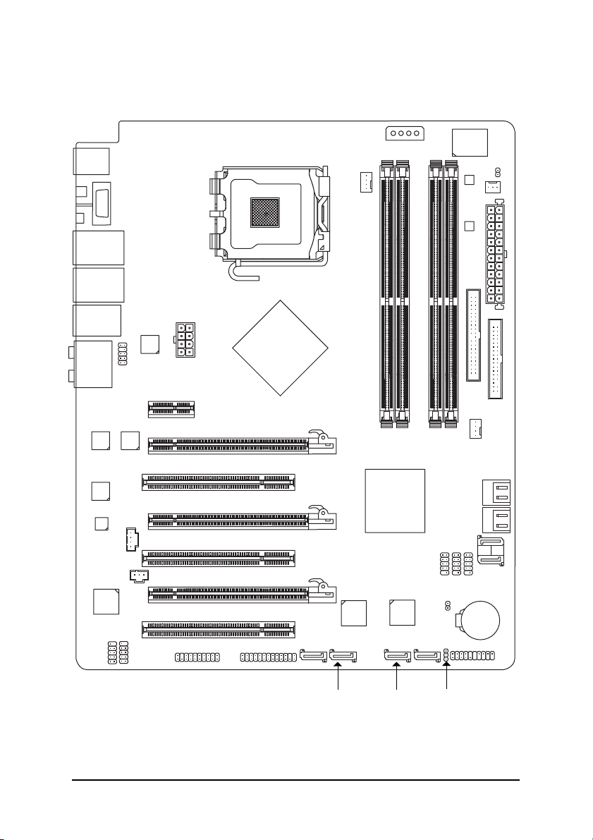
GA-N680SLI-DQ6 Motherboard Layout
OPTICAL
R_1394
KB_MS
COMA
USB_LAN1
USB_LAN2
DUAL_LAN
AUDIO
Marvell
88E8052
Marvell
88E8056
CODEC
CD_IN
F_AUDIO
Marvell
88E1116
Marvell
88E1116
PCIE_16_1
PCI1
PCIE_8
PCI2
ATX_12V_2X
PCIE_1
LGA775
®
nVIDIA
nForce 680i SLI
Northbridge
PCIE_12V
CPU_FAN
GA-N680SLI-DQ6
DDRII1
®
nVIDIA
nForce 680i SLI
Southbridge
DDRII2
DDRII3
SATAII0
IT8718
BACKUP
BIOS
MAIN
BIOS
IDE
DDRII4
SATAII2
PWR_FAN
ATX
SYS_FAN
SATAII3
FDD
SATAII4
CI
SATAII5
SPDIF_IN
TSB43AB23
F1_1394
PCI3
F2_1394
PCIE_16_2
TPM
LPT
GSATAII1-0
- 7 -
GIGABYTE
SATA2
GSATAII1-1
GIGABYTE
SATA2
GSATAII2-0
GSATAII2-1
PWR_LED
F_USB3
CLR_CMOS
F_USB1
F_USB2
BATTERY
F_PANEL
SATAII1
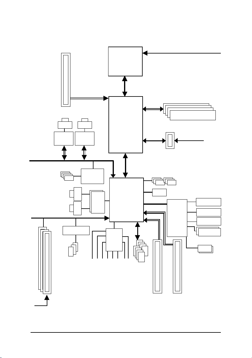
Block Diagram
PCIe CLK
(100 MHz)
PCI Express x16
CPU CLK+/-(333/266/200/133 MHz)
LGA775
Processor
Host Interface
DDRII 800/667/533 MHz DIMM
Marvell
88E8052
PCI Express Bus
4 SATA 3Gb/s
PCI Bus
3 PCI
PCI CLK
(33 MHz)
LAN
RJ45
x1
LAN2
LAN1
TSB43AB23
LAN
RJ45
Marvell
88E8056
x1
GIGABYTE
SATA2 x 2
RJ45
RJ45
3 IEEE1394a
Surround Speaker Out
®
nVIDIA
nForce 680i SLI
Northbridge
®
nVIDIA
nForce 680i SLI
Marvell
88E1116 x 2
Southbridge
LPC BUS
CODEC
Line-In
SPDIF In
10 USB
Ports
SPDIF Out
PCI Express x8
MIC
Line-Out
Side Speaker Out
Center/Subwoofer Speaker Out
Dual Channel Memory
1 PCI Express x1
PCIe CLK
(100 MHz)
6 SATA 3Gb/s
ATA33/66/100/133
IDE Channel
IT8718
PCI Express x16
Floppy
LPT Port
COM Port
PS/2 KB/Mouse
Dual BIOS
- 8 -

Chapter 1 Hardware Installation
1-1 Considerations Prior to Installation
Preparing Your Computer
The motherboard contains numerous delicate electronic circuits and components which can
become damaged as a result of electrostatic discharge (ESD). Thus, prior to installation, please
follow the instructions below:
1. Please turn off the computer and unplug its power cord.
2. When handling the motherboard, avoid touching any metal leads or connectors.
3. It is best to wear an electrostatic discharge (ESD) cuff when handling electronic components
(CPU, RAM).
4. Prior to installing the electronic components, please have these items on top of an antistatic pad or
within a electrostatic shielding container.
5. Please verify that the power supply is switched off before unplugging the power supply connector
from the motherboard.
Installation Notices
1. Prior to installation, please do not remove the stickers on the motherboard. These stickers are required
for warranty validation.
2. Prior to the installation of the motherboard or any hardware, please first carefully read the information
in the provided manual.
3. Before using the product, please verify that all cables and power connectors are connected.
4. To prevent damage to the motherboard, please do not allow screws to come in contact with the
motherboard circuit or its components.
5. Please make sure there are no leftover screws or metal components placed on the motherboard or
within the computer casing.
6. Please do not place the computer system on an uneven surface.
7. Turning on the computer power during the installation process can lead to damage to system
components as well as physical harm to the user.
8. If you are uncertain about any installation steps or have a problem related to the use of the product,
please consult a certified computer technician.
English
Instances of Non-Warranty
1. Damage due to natural disaster, accident or human cause.
2. Damage as a result of violating the conditions recommended in the user manual.
3. Damage due to improper installation.
4. Damage due to use of uncertified components.
5. Damage due to use exceeding the permitted parameters.
6. Product determined to be an unofficial Gigabyte product.
Hardware Installation- 9 -

English
1-2 Feature Summary
TM
CPU LGA775 for Intel® Core
2 Extreme quad-core / Core
CoreTM 2 Quad / CoreTM 2 Duo / Pentium® processor Extreme Edition /
Pentium® D / Pentium® 4 / Celeron® D
L2 cache varies with CPU
Front Side Bus Supports 1333/1066/800/533 MHz FSB
Chipset nVIDIA® nForce 680i SLI
(Northbridge: C55XE, Southbridge: MCP55PXE)
LAN Onboard Marvell 88E8052/88E8056 chip (10/100/1000 Mbit)
2 Onboard Marvell 88E1116 phy (10/100/1000 Mbit)
Audio Onboard Realtek ALC888 DD chip
Supports High Definition Audio
Supports 2 / 4 / 6 / 8 channel audio
Supports DTS (dts NEO : PC) function
Supports Dolby Digital Live
Supports S/PDIF In/Out connection
Supports CD In connection
IEEE 1394 Onboard T.I. TSB43AB23 chip
3 IEEE 1394a ports
Storage nVIDIA® nForce 680i SLI Southbridge
- 1 FDD connector supported by I/O controller, allowing connection of
1 FDD device
- 1 IDE connector with Ultra DMA-33, ATA-66/100/133 support,
allowing connection of 2 IDE devices
- 6 SATA 3Gb/s connectors (SATAII0, SATAII1, SATAII2, SATAII3, SATAII4,
SATAII5), allowing connection of 6 SATA 3Gb/s devices
- Supports data RAID 0, RAID 1, RAID 0+1, RAID 5 and JBOD for
Serial ATA
GIGABYTE SATA2 x 2 Controller
- 4 SATA 3Gb/s connectors (GSATAII1-0, GSATAII1-1, GSATAII2-0,
GSATAII2-1),
allowing connection of 4 SATA 3Gb/s devices
- Supports data RAID 0, RAID 1 and JBOD for Serial ATA
O.S Support Microsoft Windows 2000/XP
Memory 4 DDRII DIMM memory slots (supports up to 8 GB memory)
Supports dual channel DDRII 800/667/533 unbuffered DIMMs
Supports 1.8V DDRII DIMMs
Supports ECC type DRAM
Expanstion Slots 2 PCI Express x16 slots
1 PCI Express x8 slot
1 PCI Express x1 slot
3 PCI slots
TM
2 Extreme dual-core /
(Note 1)
GA-N680SLI-DQ6 Motherboard - 10 -

Internal Connectors 1 24-pin ATX power connector
1 8-pin ATX 12V power connector
1 4-pin PCIe 12V power connector
1 floppy connector
1 IDE connector
10 SATA 3Gb/s connectors
1 CPU fan connector
1 system fan connector
1 power fan connector
1 front panel connector
1 front audio connector
1 CD In connector
1 S/PDIF In connector
3 USB 2.0/1.1 connectors for additional 6 ports by cables
2 IEEE 1394a connectors for additional 2 ports by cables
1 TPM connector
1 LPT connector
1 power LED connector
1 Chassis Intrusion connector
Rear Panel I/O 1 PS/2 keyboard port
1 PS/2 mouse port
1 serial port
1 IEEE 1394a port
1 S/PDIF out port (optical)
4 RJ-45 port
4 USB 2.0/1.1 ports
6 audio jacks (Line In / Line Out / MIC In / Surround Speaker Out (Rear
Speaker Out) / Center/Subwoofer Speaker Out / Side Speaker Out)
I/O Control IT8718 chip
Hardware Monitor System voltage detection
CPU / System temperature detection
CPU / System / Power fan speed detection
CPU warning temperature
CPU / System / Power fan failure warning
CPU / System smart fan control
BIOS 2 4 Mbit flash ROM
Use of licensed AWARD BIOS
Supports Dual BIOS
English
Hardware Installation- 11 -

English
Additional Features Supports @BIOS
Supports Download Center
Supports Q-Flash
Supports EasyTune
(Note 2)
Supports Xpress Install
Supports Xpress Recovery2
Supports Xpress BIOS Rescue
Bundle Software Norton Internet Security (OEM revision)
Overclocking Over Voltage via BIOS (CPU, DDRII, NB/PCIE, SB/PCIE, FSB,
HT-Link, SB Standby)
- CPU Voltage :
Adjustable CPU voltage at 0.025V
(Note 3)
- DDRII Voltage :
Adjustable DDRII voltage at 0.025V
(Adjustable range from 0.025V to 0.775V)
- NB/PCIE Voltage :
Adjustable PCIe voltage at 0.05V
(Adjustable range from 0.05V to 0.20V)
- SB/PCIE Voltage :
Adjustable PCIe voltage at 0.05V
(Adjustable range from 0.05V to 0.75V)
- FSB Voltage :
Adjustable FSB voltage at 0.05V
(Adjustable range from 0.05V to 0.35V)
- HT-Link Voltage :
Adjustable HT-Link voltage at 0.05V
(Adjustable range from 0.05V to 0.35V)
- SB Standby Voltage :
Adjustable SB Standby voltage at 0.05V
(Adjustable range from 0.05V to 0.15V)
Over Clock via BIOS (CPU, DDRII, PCIE)
- PCI Express x16 Clock:
Allows 1 MHz increment from 100 MHz to 150 MHz
- PCI Express x8 Clock:
Allows 1 MHz increment from 100 MHz to 150 MHz
- Adjustable CPU, DDRII frequencies
Form Factor ATX form factor; 30.5cm x 24.4cm
(Note 1) To use a DDR II 800/667 memory module on the motherboard, you must install a 1333/1066/
800 MHz FSB processor.
(Note 2) EasyTune functions may vary depending on different motherboards.
(Note 3) The adjustable range is dependent on CPUs.
GA-N680SLI-DQ6 Motherboard - 12 -
1-3 Installation of the CPU and CPU Cooler
Before installing the CPU, please comply with the following conditions:
1. Please make sure that the motherboard supports the CPU.
2. Please take note of the one indented corner of the CPU. If you install the CPU in the
wrong direction, the CPU will not insert properly. If this occurs, please change the
insert direction of the CPU.
3. Please add an even layer of heat sink paste between the CPU and CPU cooler.
4. Please make sure the CPU cooler is installed on the CPU prior to system use,
otherwise overheating and permanent damage of the CPU may occur.
5. Please set the CPU host frequency in accordance with the processor specifications. It
is not recommended that the system bus frequency be set beyond hardware specifications since it does not meet the required standards for the peripherals. If you wish to set
the frequency beyond the proper specifications, please do so according to your hardware specifications including the CPU, graphics card, memory, hard drive, etc.
HT functionality requirement content :
Enabling the functionality of Hyper-Threading Technology for your computer system requires
all of the following platform components:
- CPU: An Intel® Pentium 4 Processor with HT Technology
- Chipset: An Intel® Chipset that supports HT Technology
- BIOS: A BIOS that supports HT Technology and has it enabled
- OS: An operation system that has optimizations for HT Technology
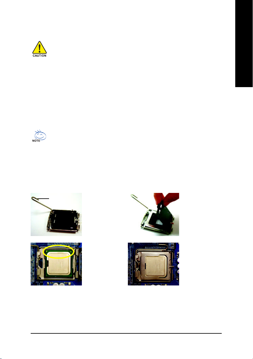
1-3-1 Installation of the CPU
Metal Lever
Fig. 1
Gently lift the metal
lever located on the
CPU socket to the
upright position.
English
Fig. 2
Remove the plastic
covering on the CPU
socket.
Fig. 3
Notice the small gold
colored triangle located
on the edge of the CPU
socket. Align the
indented corner of the
CPU with the triangle and gently insert the CPU into
position. (Grasping the CPU firmly between your
thumb and forefinger, carefully place it into the socket
in a straight and downwards motion. Avoid twisting or
bending motions that might cause damage to the CPU
during installation.)
Fig. 4
Once the CPU is
properly inserted,
please replace the
load plate and push the
metal lever back into
its original position.
Hardware Installation- 13 -
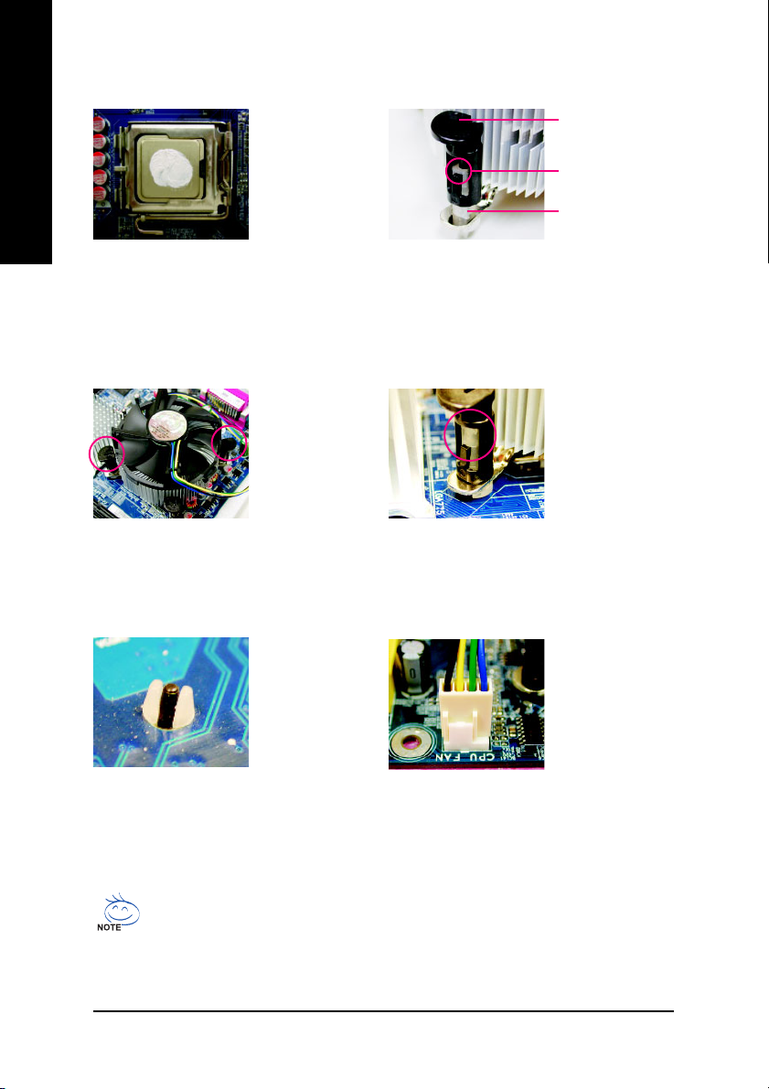
1-3-2 Installation of the CPU Cooler
Male Push Pin
English
Fig.1
Please apply an even layer of CPU cooler paste
on the surface of the installed CPU.
Fig. 3
Place the CPU cooler atop the CPU and make
sure the push pins aim to the pin hole on the
motherboard.Pressing down the push pins
diagonally.
The top of Female Push Pin
Female Push Pin
Fig. 2
(Turning the push pin along the direction of arrow is to
remove the CPU cooler, on the contrary, is to install.)
Please note the direction of arrow sign on the male
push pin doesn't face inwards before installation. (This
instruction is only for Intel boxed fan)
Fig. 4
Please make sure the Male and Female push pin
are joined closely. (for detailed installation
instructions, please refer to the CPU cooler installation section of the user manual)
Fig. 5
Please check the back of motherboard after
installing. If the push pin is inserted as the picture,
the installation is complete.
The CPU cooler may adhere to the CPU as a result of hardening of the heat paste. To prevent
such an occurrence, it is suggested that either thermal tape rather than heat paste be used for
heat dissipation or using extreme care when removing the CPU cooler.
GA-N680SLI-DQ6 Motherboard - 14 -
Fig. 6
Finally, please attach the power connector of the
CPU cooler to the CPU fan header located on the
motherboard.
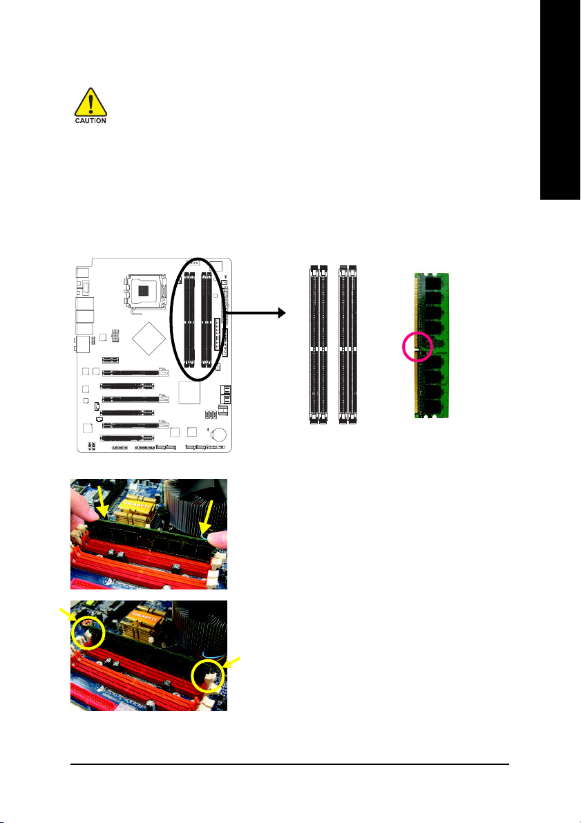
1-4 Installation of Memory
Before installing the memory modules, please comply with the following conditions:
1. Please make sure that the memory used is supported by the motherboard. It is
recommended that memory of similar capacity, specifications and brand be used.
2. Before installing or removing memory modules, please make sure that the computer
power is switched off to prevent hardware damage.
3. Memory modules have a foolproof insertion design. A memory module can be installed
in only one direction. If you are unable to insert the module, please switch the direction.
The motherboard supports DDRII memory modules, whereby BIOS will automatically detect memory
capacity and specifications. Memory modules are designed so that they can be inserted only in one direction.
The memory capacity used can differ with each slot.
Notch
DDRII
English
Fig.1
The DIMM socket has a notch, so the DIMM memory
module can only fit in one direction. Insert the DIMM memory
module vertically into the DIMM socket. Then push it down.
Fig.2
Close the plastic clip at both edges of the DIMM sockets to
lock the DIMM module.
Reverse the installation steps when you wish to remove
the DIMM module.
Hardware Installation- 15 -
English
Dual Channel Memory Configuration
The GA-N680SLI-DQ6 supports the Dual Channel Technology. After operating the Dual Channel Technology, the bandwidth of memory bus will double.
The GA-N680SLI-DQ6 includes 4 DIMM sockets, and each Channel has two DIMM sockets as
following:
Channel 0 : DDRII1, DDRII2
Channel 1 : DDRII3, DDRII4
If you want to operate the Dual Channel Technology, please note the following explanations due to the
limitation of chipset specifications.
1. Dual Channel mode will not be enabled if only one DDRII memory module is installed.
2. To enable Dual Channel mode with two or four memory modules (it is recommended to use
memory modules of identical brand, size, chips, and speed), you must install them into DIMM
sockets of the same color.
The following is a Dual Channel Memory configuration table:
(DS: Double Side, SS: Single Side, "--": Empty)
DDRII1 DDRII2 DDRII3 DDRII4
2 memory modules
4 memory modules
If two memory modules are to be used to achieve Dual Channel mode, we recommend
installing them in DDRII1 and DDRII3 DIMM sockets.
DS/SS - - DS/SS - -
- - DS/SS - - DS/SS
DS/SS DS/SS DS/SS DS/SS
GA-N680SLI-DQ6 Motherboard - 16 -
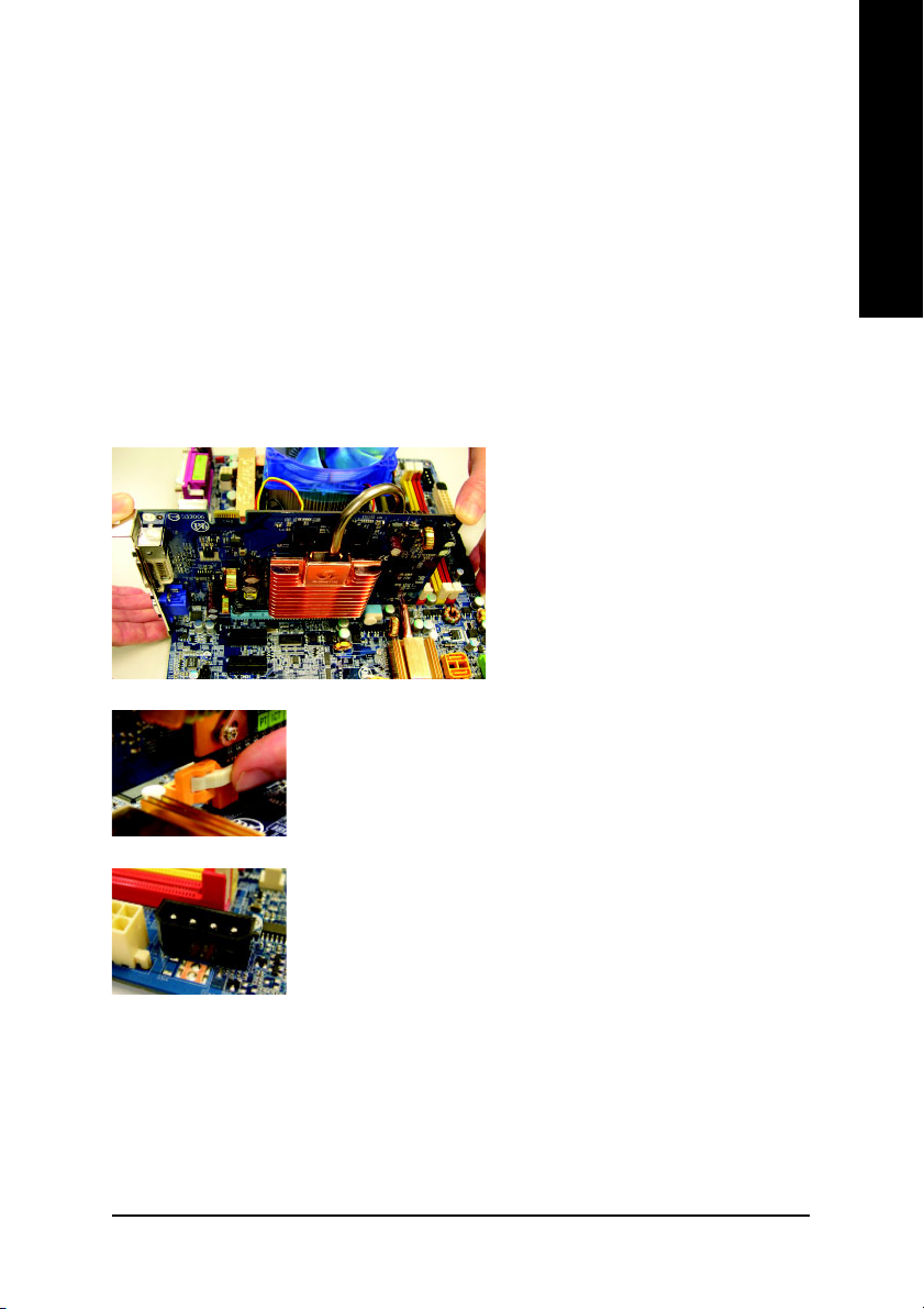
1-5 Installation of Expansion Cards
To install your expansion card, follow the steps below.
1. Disconnect your system from its power source and read the expansion card's installation manual
before installing the expansion card in the computer.
2. Remove your computer's chassis cover, screws and slot bracket from the computer. Ground
yourself to prevent damage to your computer resulting from Electrostatic discharge (ESD).
3. Press the expansion card firmly into the expansion slot in the motherboard.
4. Make sure the metal contacts on the card are fully seated in the slot.
5. Replace the screw to secure the slot bracket of the expansion card.
6. Replace your computer's chassis cover.
7. Power on the computer, if necessary, configure required settings for the expansion card in system
BIOS Setup.
8. Install related driver in the operating system.
For example: Installing a PCI Express x16 VGA card:
To install the VGA card:
Please align the VGA card with the PCI Express x16 slot and press down on the card.
Make sure the VGA card is locked by the
small white drawable bar.
To remove the VGA card:
When you try to uninstall the VGA card on the PCI Express x16 slot, you
can press the latch as the picture to the left shows to release the card.
English
The motherboard includes a PCIE_12V power connector, which provides
extra power to the onboard PCI Express x16 slot. When installing two
graphics cards, please connect the power cable from the power supply to
this connector.
Hardware Installation- 17 -
English
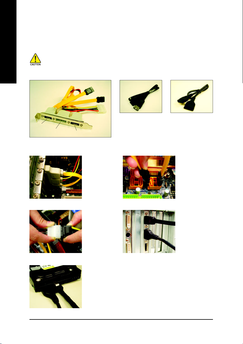
1-6 Connecting the e-SATA Cable Kit
The e-SATA cable kit allows you to connect external SATA device(s) to your system by expanding the
internal SATA port(s) to the chassis back panel.
• Turn off your system and the power switch on the power supply before installing or
removing the SATA bracket and SATA power cable to prevent damage to hardware.
• Insert the SATA signal cable and SATA power cable securely into the corresponding connectors when installing.
SATA Bracket
SATA Signal Cable SATA Power Cable
The e-SATA cable kit includes one SATA bracket,
e-SATA
Connector
Power
Connector
e-SATA
Connector
one SATA signal cable, and one SATA power cable.
Follow the steps below to install the e-SATA cable kit:
Step 1:
Locate one free PCI
slot and secure the
SATA bracket to the
chassis back panel
with a screw.
Step 3:
Connect the power
cable from the
bracket to the power
supply.
Step 5:
Connect the other ends of the SATA signal cable and SATA power cable
to your SATA devices. For SATA device in external enclosure, you only
need to connect the SATA signal cable. Before connecting the SATA signal
cable, make sure to turn off the power of the external enclosure.
Step 2:
Connect the SATA
cable from the
bracket to the SATA
port on your
motherboard.
Step 4:
Plug one end of the
SATA signal cable into
the e-SATA connector on the bracket.
Then attach the SATA
power cable to the
power connector on
the bracket.
GA-N680SLI-DQ6 Motherboard - 18 -
1-7 Setup of SLI (Scalable Link Interface) Configuration
nVIDIA® nForce 680i SLI offers blistering graphics performance with the ability to bridge two NVIDIA SLIready PCI ExpressTM graphics cards! The SLI design takes advantage of the increased bandwidth of
the PCI ExpressTM bus architecture, features hardware and software innovations within NVIDIA GPU
(graphics processing unit) and the nVIDIA® nForce 680i SLI chipset. Together, the NVIDIA SLI technologies work seamlessly to allow two graphics cards to operate in parallel and share the work and deliver
heart-pounding PC performance. This section introduces steps to configure an SLI system on the
GA-N680SLI-DQ6 motherboard.
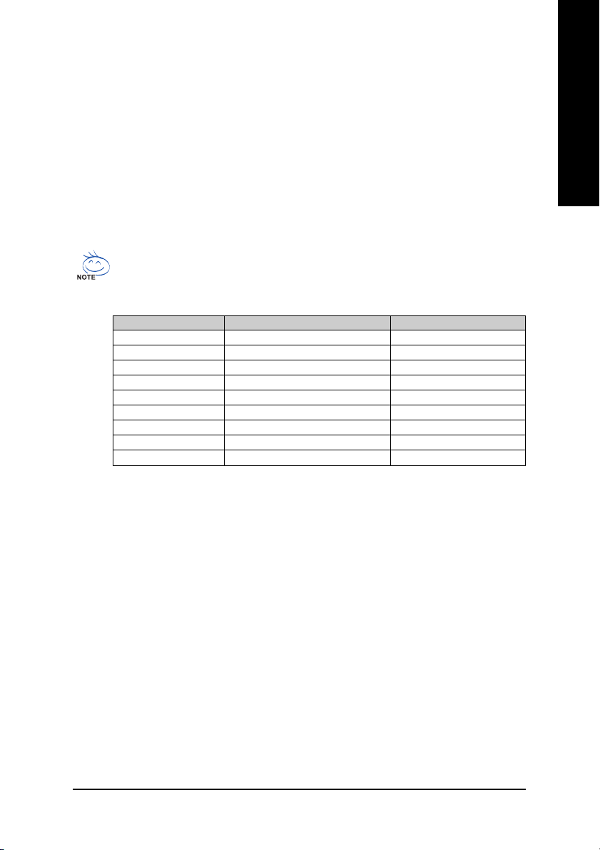
Before you begin--
The exact power requirements will depend on your overall system configurations. You need
a power supply that can provide sufficient and stable power to your system and the two SLI
graphics cards. Please refer to the table below to check recommended power for different
systems.
System configuration System A System B
Processors Intel QX6700 Intel X6800
PCIE x16 video cards 2±iNVIDIA 6800 Ultra cards 2±iNVIDIA 6600 GT cards
DDR memory modules 4 DIMMs 2 DIMMs
Hard drives/Optical drives 4 hard drives + 2 optical drives 1 hard drives + 1 optical drives
Expansion cards 1 PCIE x1 card + 2 PCI cards 0
USB devices 10 4
IEEE 1394 devices 1 0
Required +12V current 25A or above 20A or above
Power supply requirement 500W or above 350W or above
English
If you wish to enable the SLI function, install two SLI-ready graphics cards into the PCIE_16_1 and
PCIE_16_2 slots. (It is recommended to use graphics cards of identical brand and chips. For example:
GIGABYTE GV-NX76T256D-RH).
If you want to set up a single graphics card system, we recommend installing the graphics card on the
PCIE_16_1 slot to ensure better display performance.
Hardware Installation- 19 -
English
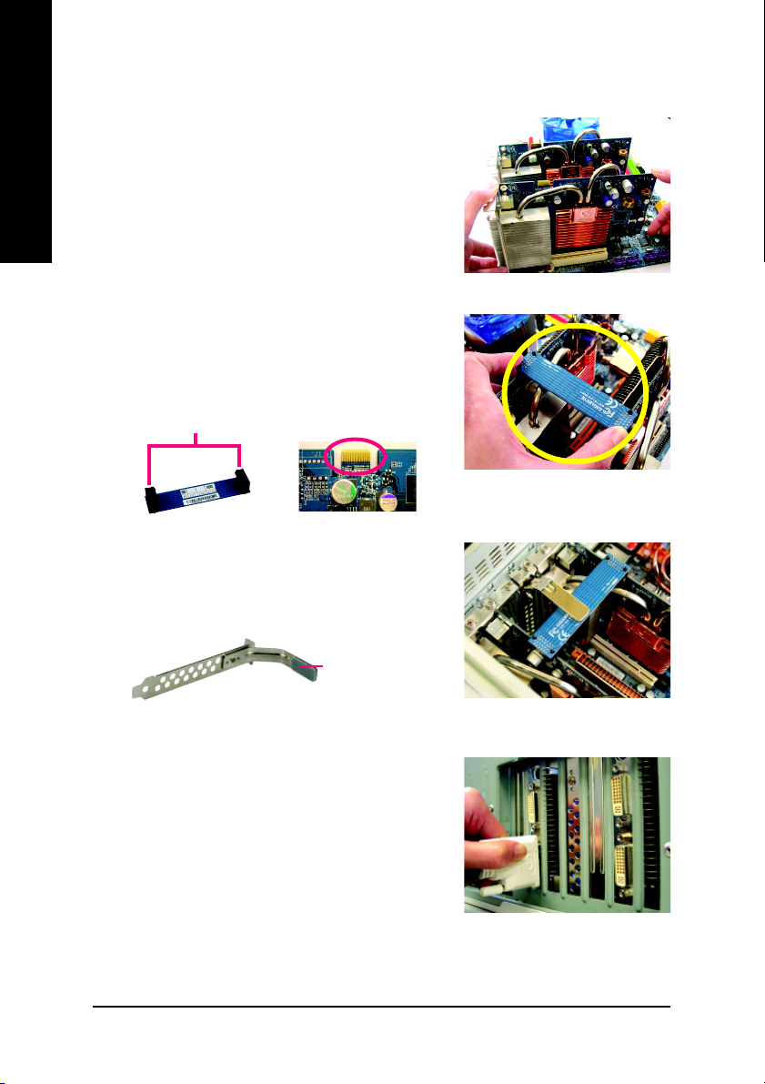
Connecting Two Graphics Cards:
Step 1: Observe the steps in "1-5 Installation of Expansion Cards"
and install two SLI-ready graphics cards of the same
model to the PCIE_16_1 and PCIE_16_2 slots.
Step 2: Insert the SLI bridge (the GC-SLICON6) to the SLI gold
edge connector on top of both cards. Make sure the two
mini female slots on the bridge connector securely fit
onto the SLI gold edge connetors of both cards.
Female slots on the bridge
connector
Gold edge connector on the top
of graphics card
Step 3: In order to securely fix the bridge connector beween the
two cards, you must install the retention bracket included with the motherboard and secure the retention
bracket to the chassis back panel with a screw.
place this part on the top of
the bridge connector.
retention bracket
Step 4: Plug the display cable into the graphics card which on
the PCIE_16_1 slot
(Note)
.
(Note) If you want to enable the SLI function, you must plug the display cable into the graphics card
which on the PCIE_16_1 slot.
GA-N680SLI-DQ6 Motherboard - 20 -
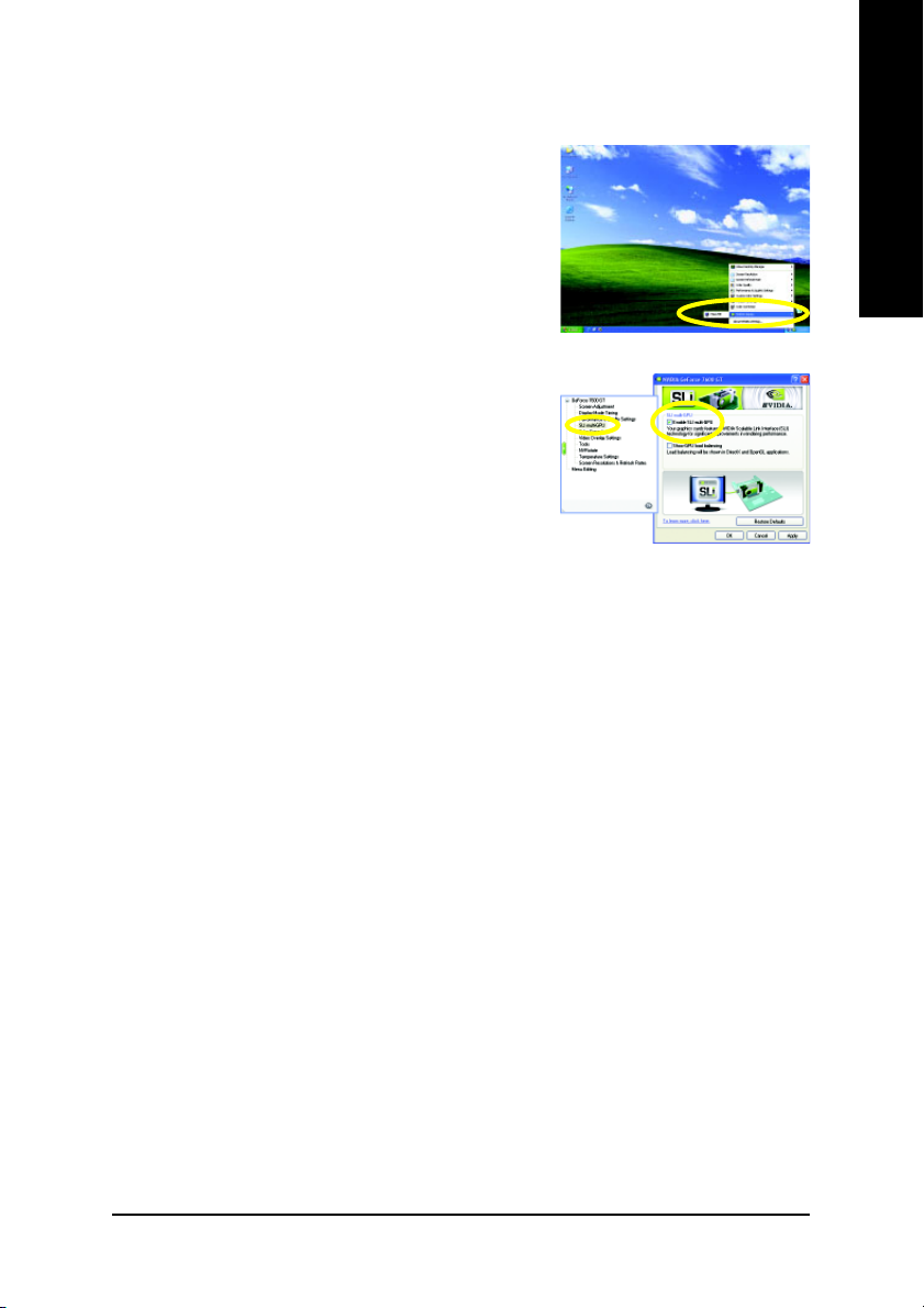
Graphics Card Driver Setting:
Step 1: After installing graphics card driver in operating system,
right-click the NVIDIA icon in your system tray and then
select NVIDIA Display. The NVIDIA control panel will
appear.
Step 2: Select SLI multi-GPU from the side menu and then
select the Enable SLI multi-GPU checkbox in the SLI
multi-GPU dialog box. System will restart after you
click Apply. Then the SLI configuration is completed.
English
Hardware Installation- 21 -
English
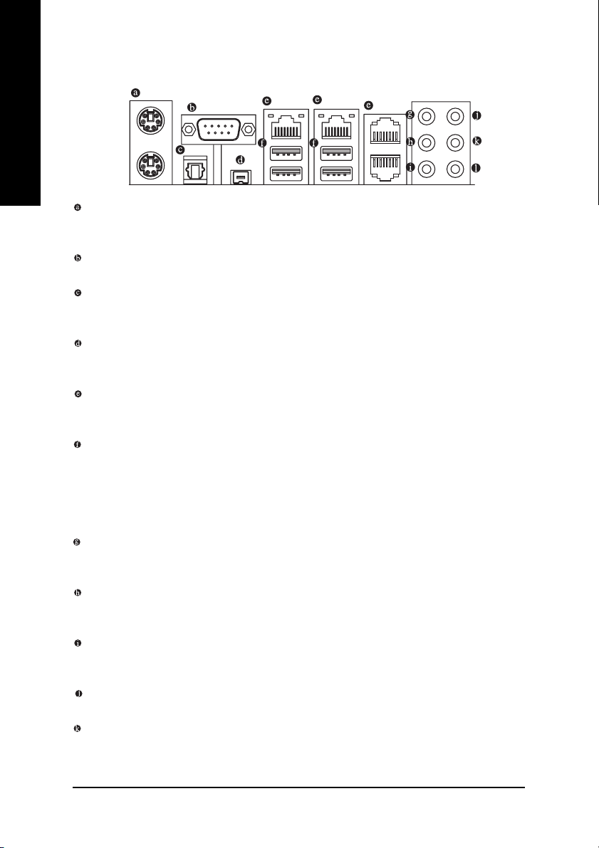
1-8 I/O Back Panel Introduction
PS/2 Keyboard and PS/2 Mouse Connector
To install a PS/2 port keyboard and mouse, plug the mouse to the upper port (green) and the
keyboard to the lower port (purple).
COMA
Connects to serial-based mouse or data processing devices.
OPTICAL
The S/PDIF optical output port is capable of providing digital audio to external speakers or
compressed AC3 data to an external Dolby Digital Decoder via an optical cable.
IEEE 1394 Port (4 Pins Connector)
Serial interface standard set by Institute of Electrical and Electronics Engineers, which has features
like high speed, high bandwidth and hot plug.
LAN Port
The provided Internet connection is Gigabit Ethernet , providing data transfer speeds of 10/100/
1000 Mbps.
USB Port
Before you connect your device(s) into USB connector(s), please make sure your device(s) such
as USB keyboard, mouse, scanner, zip, speaker...etc. have a standard USB interface. Also
make sure your OS supports USB controller. If your OS does not support USB controller, please
contact OS vendor for possible patch or driver upgrade. For more information please contact your
OS or device(s) vendors.
Center/Subwoofer Speaker Out
The default Center/Subwoofer Speaker Out jack. Center/Subwoofer speakers can be connected to
Center/Subwoofer Speaker Out jack.
Surround Speaker Out (Rear Speaker Out)
The default Surround Speaker Out (Rear Speaker Out) jack. Rear surround speakers can be
connected to Surround Speaker Out (Rear Speaker Out) jack.
Side Speaker Out
The default Side Speaker Out jack. Surround side speakers can be connected to Side Speaker Out
jack.
Line In
The default Line In jack. Devices like CD-ROM, walkman etc. can be connected to Line In jack.
Line Out (Front Speaker Out)
The default Line Out (Front Speaker Out) jack. Stereo speakers, earphone or front surround
speakers can be connected to Line Out (Front Speaker Out) jack.
GA-N680SLI-DQ6 Motherboard - 22 -
MIC In
The default MIC In jack. Microphone must be connected to MIC In jack.
In addition to the default speakers settings, the ~ audio jacks can be reconfigured to
perform different functions via the audio software. Only microphones still MUST be connected
to the default Mic In jack ( ). Please refer to the 2-/4-/6-/8- channel audio setup steps for
detailed software configuration information.
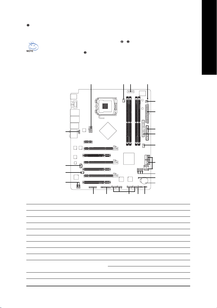
1-9 Connectors Introduction
421
1
3
6
2
English
14
15
16
18
20
1) ATX_12V_2X
2) ATX (Power Connector)
3) PCIE_12V
4) CPU_FAN
5) SYS_FAN
6) PWR_FAN
7) FDD
8) IDE
9) SATAII0 / 1 / 2 / 3 / 4 / 5
10) GSATAII1-0 / GSATAII1-1 / GSATAII2-0 /
GSATAII2-1
11) PWR_LED
7
8
5
9
17
22
12
19
10
11
13
12) BATTERY
13) F_PANEL
14) F_AUDIO
15) CD_IN
16) SPDIF_IN
17) F_USB1 / F_USB2 / F_USB3
18) F1_1394 / F2_1394
19) LPT
20) TPM
21) C I
22) CLR_CMOS
Hardware Installation- 23 -
English
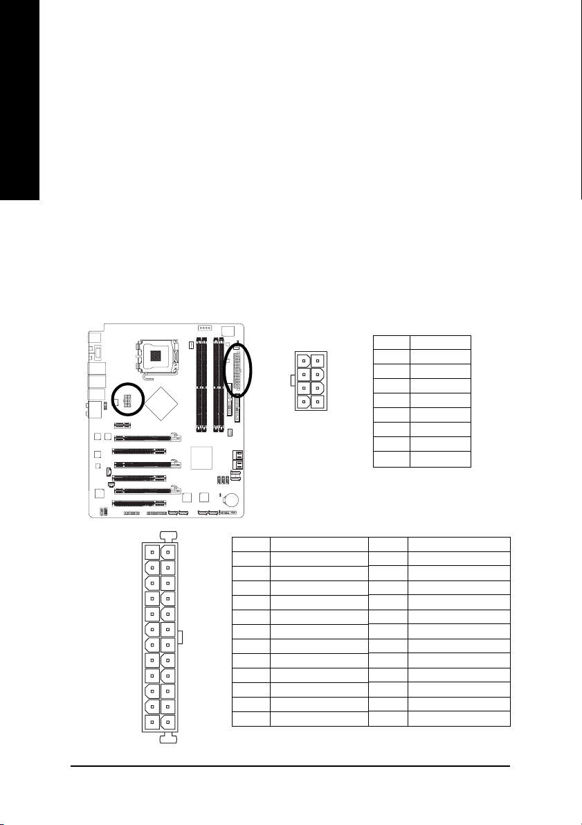
1/2) ATX_12V_2X / ATX (Power Connector)
With the use of the power connector, the power supply can supply enough stable power to all the
components on the motherboard. Before connecting the power connector, please make sure that
all components and devices are properly installed. Align the power connector with its proper
location on the motherboard and connect tightly.
The ATX 12V (2x4-pin) power connector mainly supplies power to the CPU. If the ATX 12V (2x4)
power connector is not connected, the system will not start. If you wish to install a power supply
that provides ATX 12V (2x2-pin) power connector, please connect the ATX 12V power connector
to the Pin 3, 4, 7, 8 of the onboard ATX_12V_2X power connector according to the pin definitions.
Important Use of a power supply providing an ATX 12V (2x4-pin) power connector is recommended by processor manufacturer when using Intel® Pentium® Extreme Edition series processors
(130W or greater).
Caution! Please use a power supply that is able to handle the system voltage requirements. It is
recommended that a power supply that can withstand high power consumption be used (400W or
greater). If a power supply is used that does not provide the required power, the result can lead to an
unstable system or a system that is unable to start. If you use a power supply that provides a 24-pin
ATX or 2x4 pin ATX 12V power connector, please remove the small cover on the power connector on
the motherboard before plugging in the power cord; otherwise, please do not remove it.
Pin No. Definition
8
5
ATX_12V_2X
4
1
1 GND
2 GND
3 GND
4 GND
5 +12V
6 +12V
7 +12V
8 +12V
12
24
131
ATX
Pin No. Definition
1 3.3V
2 3.3V
3 GND
4 +5V
5 GND
6 +5V
7 GND
8 Power Good
9 5V SB(stand by +5V)
10 +12V
11 +12V(Only for 24-pin ATX)
12 3.3V(Only for 24-pin ATX)
GA-N680SLI-DQ6 Motherboard - 24 -
Pin No. Definition
13 3.3V
14 -12V
15 GND
16 PS_ON(soft On/Off)
17 GND
18 GND
19 GND
20 -5V
21 +5V
22 +5V
23 +5V (Only for 24-pin ATX)
24 GND(Only for 24-pin ATX)
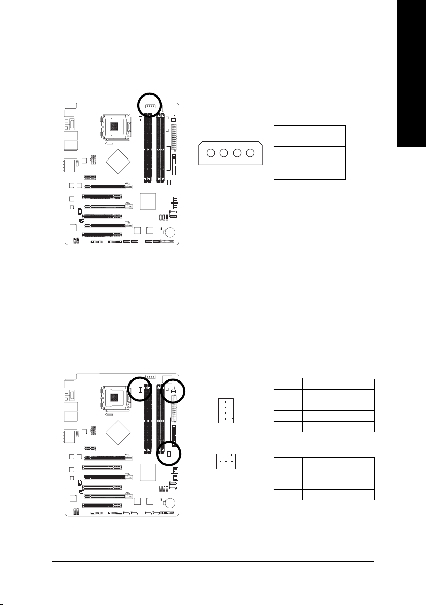
3) PCIE_12V (Power Connector)
This power connector provides extra power to the onboard PCI Express x16 slot. When installing
two graphics cards, please connect the power cable from the power supply to this connector, or
system instability may occur.
English
1
PIin No. Definition
1NC
2 GND
3 GND
4 +12V
4/5/6) CPU_FAN / SYS_FAN / PWR_FAN (Cooler Fan Power Connector)
The cooler fan power connector supplies a +12V power voltage via a 3-pin/4-pin(CPU_FAN/
SYS_FAN) power connector and possesses a foolproof connection design.
Most coolers are designed with color-coded power connector wires. A red power connector wire
indicates a positive connection and requires a +12V power voltage. The black connector wire is
the ground wire (GND).
Remember to connect the CPU/system/power fan cable to the CPU_FAN/SYS_FAN/PWR_FAN
connector to prevent CPU damage or system hanging caused by overheating.
CPU_FAN / SYS_FAN :
Pin No. Definition
1 GND
2 +12V / Speed Control
1
CPU_FAN / SYS_FAN
3 Sense
4 Speed Control
PWR_FAN
PWR_FAN :
1
Pin No. Definition
1 GND
2 +12V
3 Sense
Hardware Installation- 25 -
English
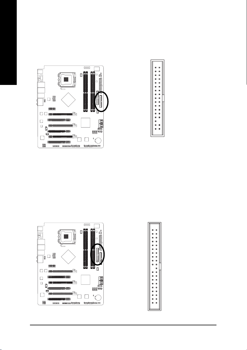
7) FDD (Floppy Connector)
The FDD connector is used to connect the FDD cable while the other end of the cable connects to
the FDD drive. The types of FDD drives supported are: 360 KB, 720 KB, 1.2 MB, 1.44 MB and
2.88 MB. Before attaching the FDD cable, please take note of the foolproof groove in the FDD
connector.
34
2
33
1
8) IDE (IDE Connector)
An IDE device connects to the computer via an IDE connector. One IDE connector can connect to one
IDE cable, and the single IDE cable can then connect to two IDE devices (hard drive or optical drive).
If you wish to connect two IDE devices, please set the jumper on one IDE device as Master and the
other as Slave (for information on settings, please refer to the instructions located on the IDE device).
Before attaching the IDE cable, please take note of the foolproof groove in the IDE connector.
40
39
GA-N680SLI-DQ6 Motherboard - 26 -
2
1
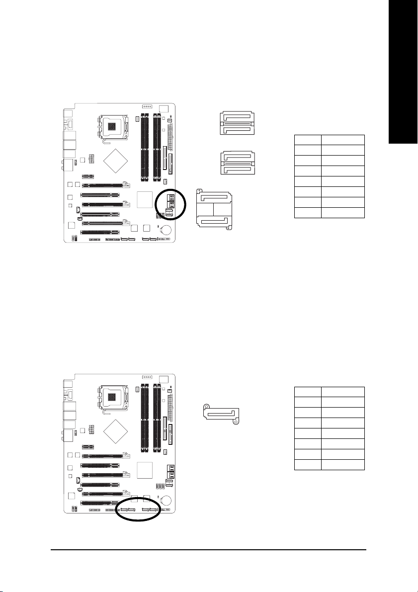
9) SATAII0 / 1 / 2 / 3 / 4 / 5 (SATA 3Gb/s Connector, Controlled by nVIDIA® nForce 680i SLI
Southbridge)
SATA 3Gb/s can provide up to 300 MB/s transfer rate. Please refer to the BIOS setting for the SATA
3Gb/s and install the proper driver in order to work properly.
1
7
SATAII5
SATAII4
7
7
1
SATAII0
SATAII1
17
17
1
17
SATAII3
SATAII2
Pin No. Definition
1 GND
2TXP
3 TXN
4 GND
5 RXN
6 RXP
7 GND
10) GSATAII1-0 / GSATAII1-1 / GSATAII2-0 / GSATAII2-1 (SATA 3Gb/s Connector, Controlled
by GIGABYTE SATA2)
SATA 3Gb/s can provide up to 300 MB/s transfer rate. Please refer to the BIOS setting for the SATA
3Gb/s and install the proper driver in order to work properly.
English
17
Pin No. Definition
1 GND
2TXP
3 TXN
4 GND
5 RXN
6 RXP
7 GND
Hardware Installation- 27 -
English
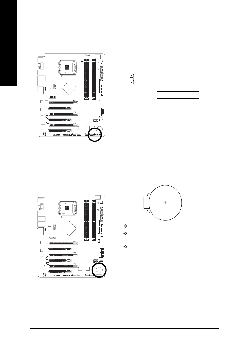
11) PWR_LED
The PWR_LED connector is connected with the system power indicator to indicate whether the
system is on/off. It will blink when the system enters suspend mode(S1).
12) BATTERY
1
Danger of explosion if battery is incorrectly replaced.
Replace only with the same or equivalent type recommended
by the manufacturer.
Dispose of used batteries according to the manufacturer's
instructions.
Pin No. Definition
1 MPD+
2 MPD-
3 MPD-
If you want to erase CMOS...
1. Turn off the computer and unplug the power cord.
2. Gently take out the battery and put it aside for about one minute.
3. Re-install the battery.
4. Plug the power cord in and turn on the computer.
GA-N680SLI-DQ6 Motherboard - 28 -
(Or you can use a metal object to connect the positive and
negative pins in the battery holder to make them short for five
seconds.)
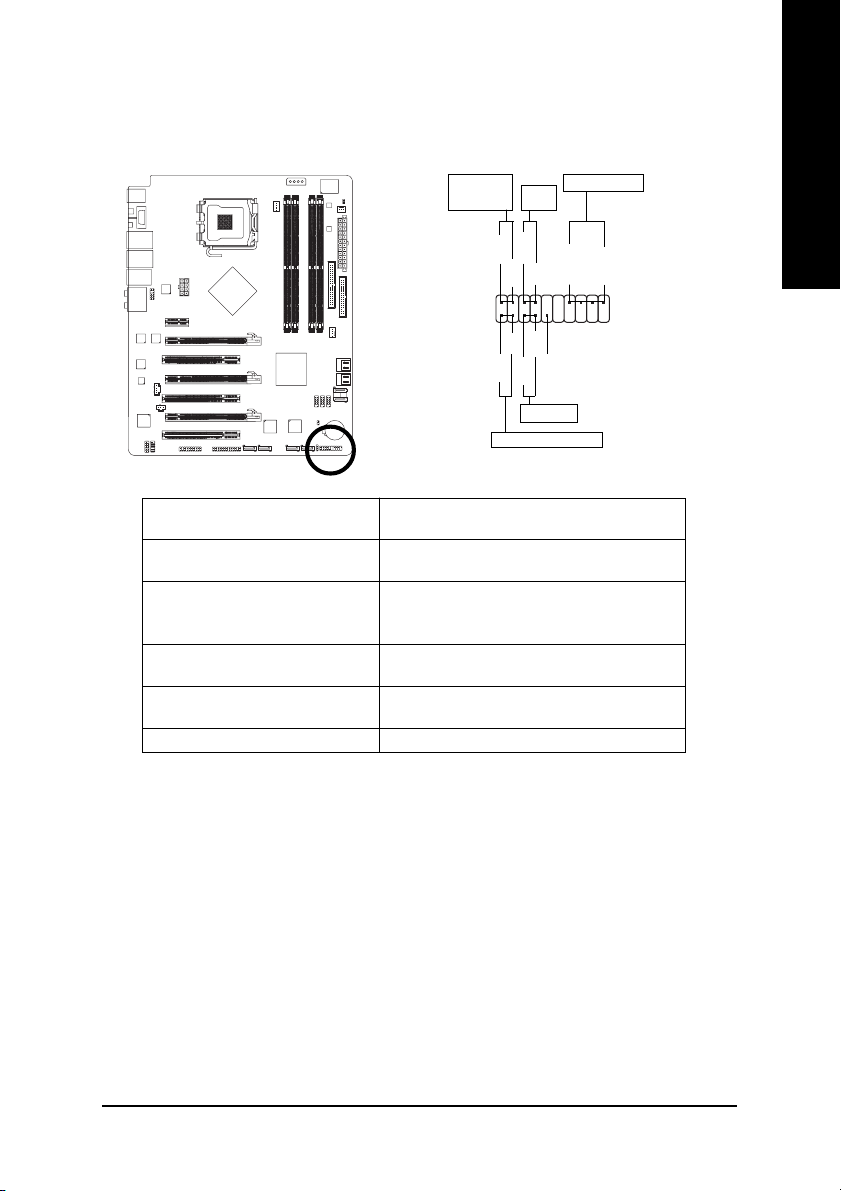
13) F_PANEL (Front Panel Jumper)
Please connect the power LED, PC speaker, reset switch and power switch etc. of your chassis
front panel to the F_PANEL connector according to the pin assignment below.
English
Message LED/
Sleep LED
Power
Power/
Switch
PW+
MSG+
MSG-
2
1
HD-
HD+
RES-
Reset Switch
IDE Hard Disk Active LED
RES+
MSG (Message LED/Power/Sleep LED) Pin 1: LED anode(+)
(Yellow) Pin 2: LED cathode(-)
PW (Power Switch) Open: Normal
(Red) Cl ose : Power On/Off
SPEAK (Speaker Connector) Pin 1: Power
(Amber) Pin 2- Pin 3: NC
Pin 4: Data(-)
HD (IDE Hard Disk Active LED) Pin 1: LED anode(+)
(Blue) Pin 2: LED cathode(-)
RES (Reset Switch) Open: Normal
(Green) Close: Reset Hardware System
NC ( Purple) NC
Speaker Connector
PW-
SPEAK+
NC
SPEAK-
20
19
Hardware Installation- 29 -
English
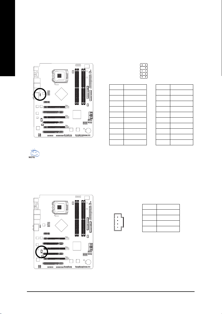
14) F_AUDIO (Front Audio Connector)
This connector supports either HD (High Definition) or AC97 front panel audio module. If you wish
to use the front audio function, connect the front panel audio module to this connector. Check the pin
assignments carefully while you connect the front panel audio module. Incorrect connection
between the module and connector will make the audio device unable to work or even damage it.
For optional front panel audio module, please contact your chassis manufacturer.
910
2
1
HD Audio:
Pin No. Definition
1 MIC2_L
2 GND
3 MIC2_R
4 -ACZ_DET
5 LINE2_R
6 FSENSE1
7 FAUDIO_JD
8 No Pin
9 LINE2_L
10 FSENSE2
By default, the audio driver is configured to support HD Audio. To connect an AC97 front panel
audio module to this connector, please refer to the instructions on page 101 about the software
settings.
AC'97 Audio:
Pin No. Definition
1 MIC
2 GND
3 MIC Power
4NC
5 Line Out (R)
6NC
7NC
8 No Pin
9 Line Out (L)
10 NC
15) CD_IN (CD IN Connector)
Connect CD-ROM or DVD-ROM audio out to the connector.
GA-N680SLI-DQ6 Motherboard - 30 -
Pin No. Definition
1 CD-L
2 GND
3 GND
4 CD-R
1
 Loading...