How it Works
Log In / Sign Up
Buy Points
How it Works
FAQ
Contact Us
Questions and Suggestions
Users
Gigabyte
Loading...
G
GA-MA785GMT-US2H (rev.1.1)
GA-MA785GMT-US2H (rev.1.3)
GA-MA785GMT-US2H (rev.3.3)
GA-MA785GPMT-UD2H
16
GA-MA785GPMT-UD2H (rev.1.0)
GA-MA785GPMT-UD2H (rev.1.1)
GA-MA785GPM-UD2H
16
GA-MA785GT-UD3H
13
GA-MA785GT-UD3H (rev.1.0)
GA-MA785GT-UD3H (rev.1.1)
GA-MA785GT-UD3H (rev.1.3)
GA-MA78G-DS3H
7
GA-MA78G-DS3HP
3
GA-MA78GM-DS2H
6
GA-MA78GM-DS2HP
7
GA-MA78GM-S2H
9
GA-MA78GM-S2HP
9
GA-MA78GM-UD2H
4
GA-MA78GM-US2H
9
GA-MA78GPM-DS2H
6
GA-MA78GPM-UD2H
4
GA-MA78LM-S2
5
GA-MA78LM-S2H
9
GA-MA78LMT-S2
5
GA-MA78LMT-S2H
14
GA-MA78LMT-US2H
10
GA-MA78LMT-US2H (rev.1.1)
GA-MA78LMT-US2H (rev.1.3)
GA-MA78LMT-US2H (rev.3.4)
GA-MA78LMT-US2H (rev.3.5)
GA-MA790FX-DQ6
5
GA-MA790FX-DS5
5
GA-MA790FXT-UD5P
6
GA-MA790FX-UD5P
6
GA-MA790GP-DS4H
10
GA-MA790GPT-UD3H
5
GA-MA790GP-UD3H
2
GA-MA790GP-UD4H
4
GA-MA790X-DS4
6
GA-MA790XT-UD4P
5
GA-MA790X-UD3P
3
GA-MA790X-UD4
4
GA-MA790X-UD4P
4
GA-MF3
3
GA-MG400
2
GA-MP61PME-S2P
8
GA-N3050N-D2P
2
GA-N3050N-D3H
2
GA-N3050N GSM PLUS
GA-N3160N-D3V
GA-N3160TN
GA-N55SLI-S4
GA-N650SLI-DS4
4
GA-N650SLI-DS4L
4
GA-N680SLI-DQ6
4
GA-P31-DS3
GA-P31-DS3L
6
GA-P31-ES3G
11
GA-P31-S3G
5
GA-P31-S3L
2
GA-P35C-DS3
8
GA-P35C-DS3R
12
GA-P35C-S3
8
GA-P35-DQ6
4
GA-P35-DS3
19
GA-P35-DS3L
20
GA-P35-DS3P
19
GA-P35-DS3R
10
GA-P35-DS4
22
GA-P35-S3
18
GA-P35-S3G
5
GA-P35-S3L
20
GA-P35-S3R
GA-P35T-DQ6
5
GA-P35T-DS3P
2
GA-P35T-DS4
2
GA-P41-ES3G
14
GA-P41T-D3
10
GA-P41T-D3P
17
GA-P41T-D3P REV 1.5
GA-P41T-D3P REV 1.6
GA-P41T-ES3G
13
GA-P41T-USB3L
13
GA-P43-ES3G
5
GA-P43T-ES3G
18
GA-P45T-ES3G
4
GA-P55-S3
9
GA-P55-S3 (rev. 1.x)
GA-P55-UD3
12
GA-P55-UD3L
24
GA-P55-UD3L (rev. 1.0)
GA-P55-UD3L (rev. 1.1)
GA-P55-UD3L (rev. 2.0)
GA-P55-UD3L (rev. 2.3)
GA-P55-UD3L-TPM
11
GA-P55-UD3L-TPM (rev. 1.1)
GA-P55-UD3P
19
GA-P55-UD3P (rev. 1.0)
GA-P55-UD3R
18
GA-P55-UD3 (rev. 1.0)
Loading...
Loading...
Nothing found
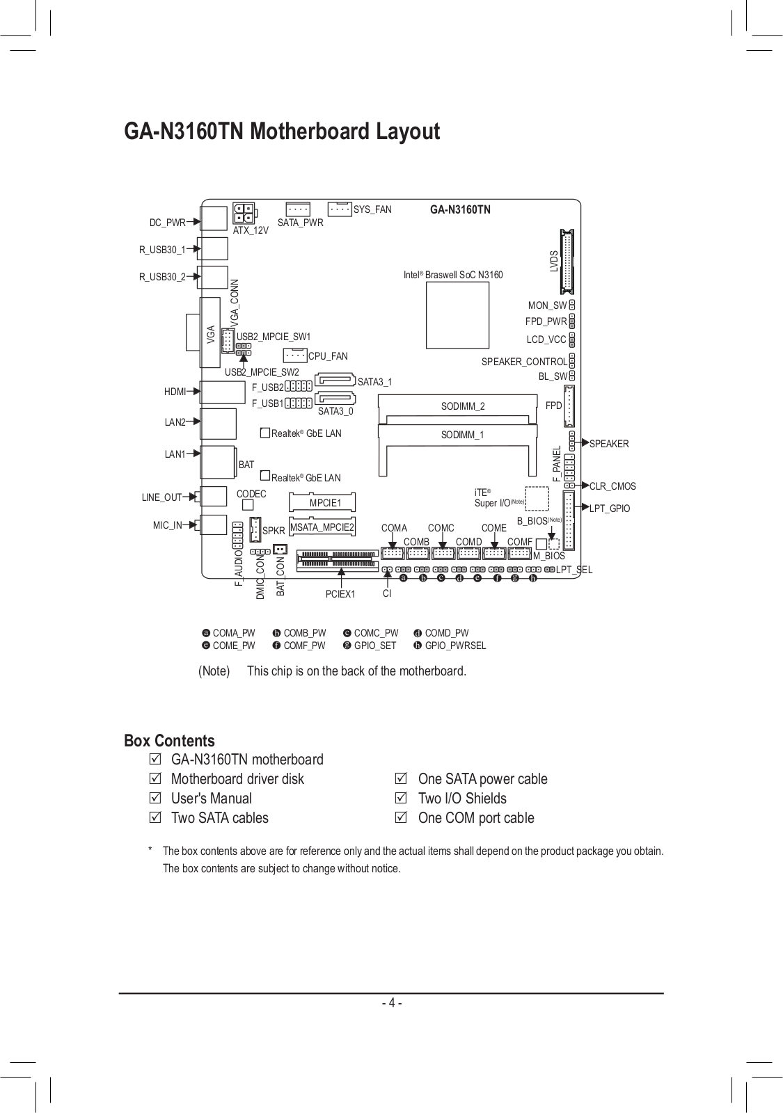
GA-N3160TN
Service Manual
34 pgs
11.35 Mb
0
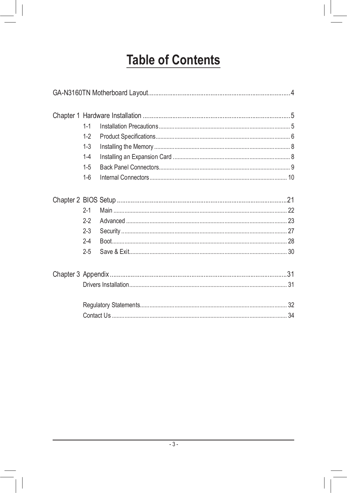
Table of contents
Loading...
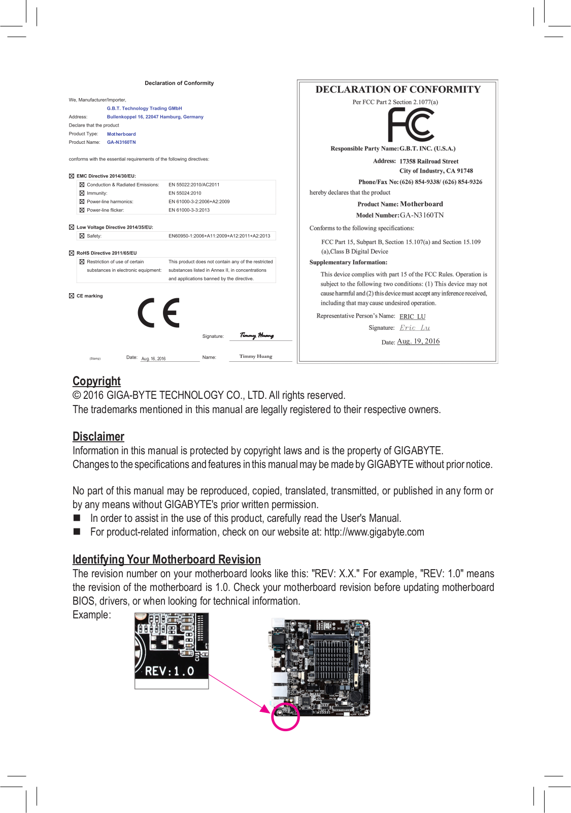
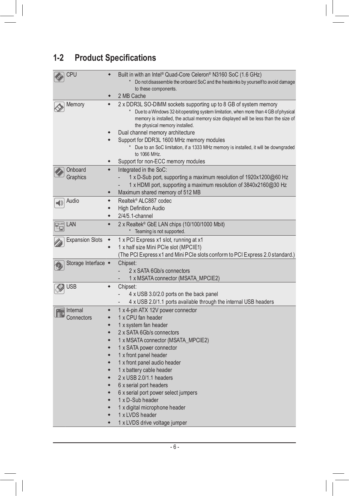
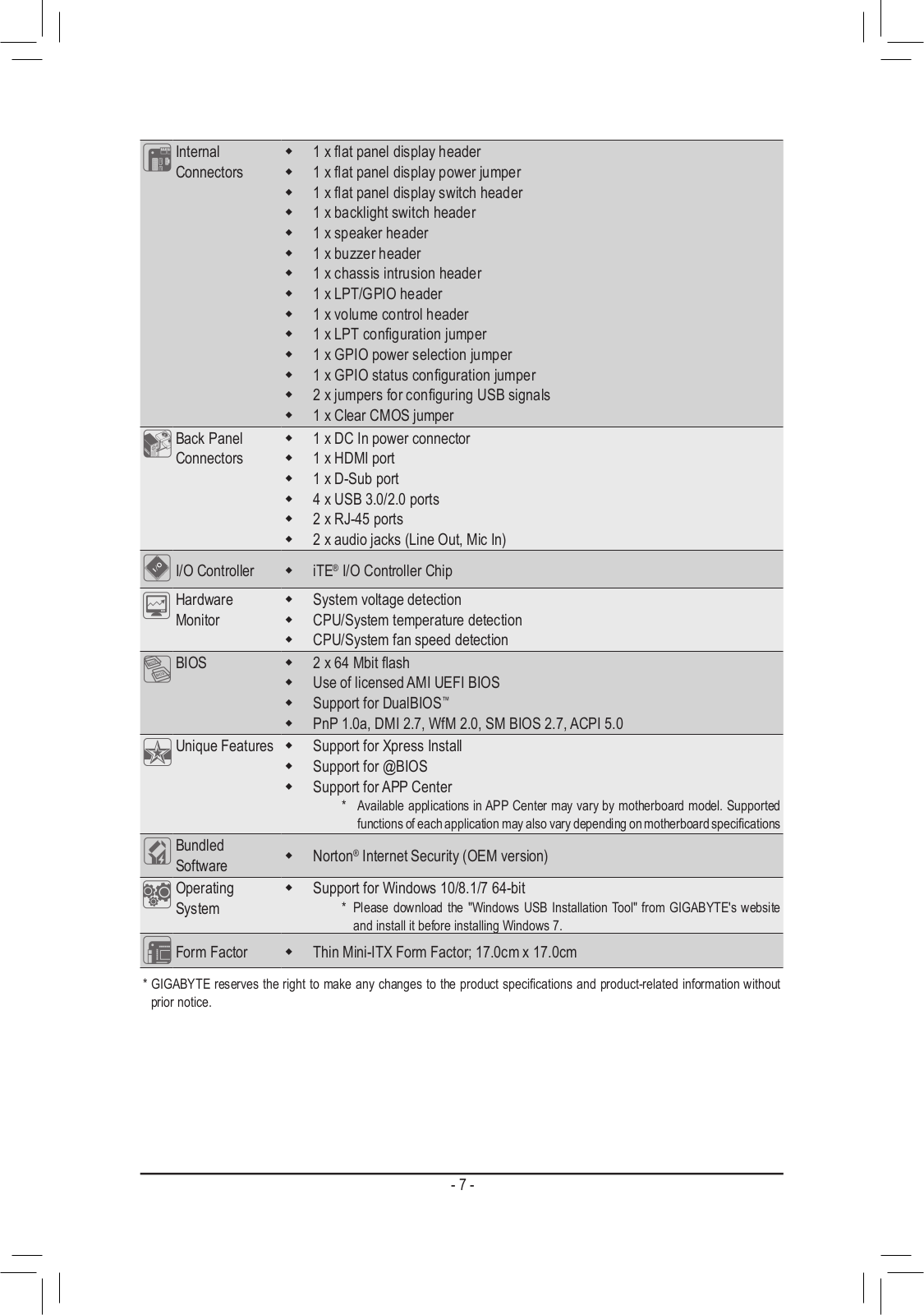
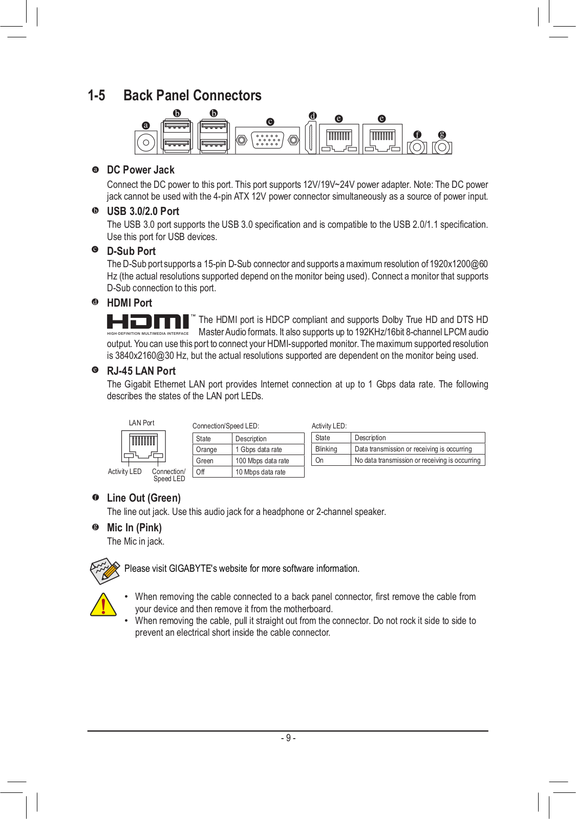
Gigabyte GA-N3160TN Service Manual
...
Gigabyte Service Manual
Download
Specifications and Main Features
Frequently Asked Questions
User Manual
Download
Loading...
+
23
hidden pages
Unhide
You need points to download manuals.
1 point = 1 manual.
You can buy points or you can get point for every manual you upload.
Buy points
Upload your manuals
 Loading...