

GIGABYTE GA-H81 Owner's Manual

GA-H81.AMP-UP
User's Manual
Rev. 1001
12ME-H81AMP-1001R
Motherboard
GA-H81.AMP-UP
Motherboard
GA-H81.AMP-UP
Aug. 12, 2013
Aug. 12, 2013
Copyright
© 2013 GIGA-BYTE TECHNOLOGY CO., LTD. All rights reserved.
The trademarks mentioned in this manual are legally registered to their respective owners.
Disclaimer
Information in this manual is protected by copyright laws and is the property of GIGABYTE.
Changes to the specications and features in this manual may be made by GIGABYTE without prior notice.
No part of this manual may be reproduced, copied, translated, transmitted, or published in any form or by
any means without GIGABYTE's prior written permission.
In order to assist in the use of this product, carefully read the User's Manual.
For product-related information, check on our website at: http://www.gigabyte.com
Identifying Your Motherboard Revision
The revision number on your motherboard looks like this: "REV: X.X." For example, "REV: 1.0" means the
revision of the motherboard is 1.0. Check your motherboard revision before updating motherboard BIOS,
drivers, or when looking for technical information.
Example:

Table of Contents
GA-H81.AMP-UP Motherboard Layout ...........................................................................4
GA-H81.AMP-UP Motherboard Block Diagram ...............................................................5
Chapter 1 Hardware Installation .....................................................................................6
1-1 Installation Precautions .................................................................................... 6
1-2 Product Specications ...................................................................................... 7
1-3 Installing the CPU ............................................................................................ 9
1-4 Installing the Memory ....................................................................................... 9
1-5 Installing an Expansion Card ......................................................................... 10
1-6 Back Panel Connectors .................................................................................. 10
1-7 Changing the Operational Amplier ...............................................................12
1-8 Internal Connectors ........................................................................................ 13
Chapter 2 BIOS Setup ..................................................................................................18
2-1 Startup Screen ............................................................................................... 18
2-2 M.I.T. .............................................................................................................. 19
2-3 System Information ........................................................................................ 24
2-4 BIOS Features ............................................................................................... 25
2-5 Peripherals ..................................................................................................... 28
2-6 Power Management ....................................................................................... 30
2-7 Save & Exit ..................................................................................................... 32
Chapter 3 Appendix ......................................................................................................33
Drivers Installation ..................................................................................................... 33
Regulatory Statements .............................................................................................. 34
Contact Us ................................................................................................................ 36
- 3 -
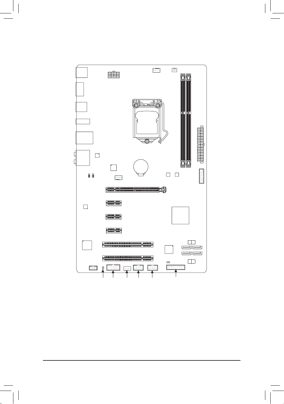
GA-H81.AMP-UP Motherboard Layout
KB_MS_USB
HDMI
R_USB30
USB_DAC
USB30_LAN
AUDIO
CAP_SW2
CODEC
iTE®
Super I/O
F_AUDIO
Realtek®
GbE LAN
CAP_SW1
ATX_12V
VIA® VL805
PCIEX16
PCIEX1_1
PCIEX1_2
PCIEX1_3
PCI1
PCI2
SYS_FAN1
CPU_FAN
LGA1150
BAT
GA-H81.AMP-UP
B_BIOS
PCIe to PCI
Bridge
CLR_CMOS
SYS_FAN3
DDR3_1
M_BIOS
Intel® H81
SATA 3
0 1
SATA 2
2 3
ATX
DDR3_2
F_USB30
COMASPDIF_O
SYS_FAN2
F_USB2
F_USB1
F_PANEL
Box Contents
5 GA-H81.AMP-UP motherboard
5 Motherboard driver disk 5 Two SATA cables
5 User's Manual 5 I/O Shield
The box contents above are for reference only and the actual items shall depend on the product package you obtain.
The box contents are subject to change without notice.
- 4 -
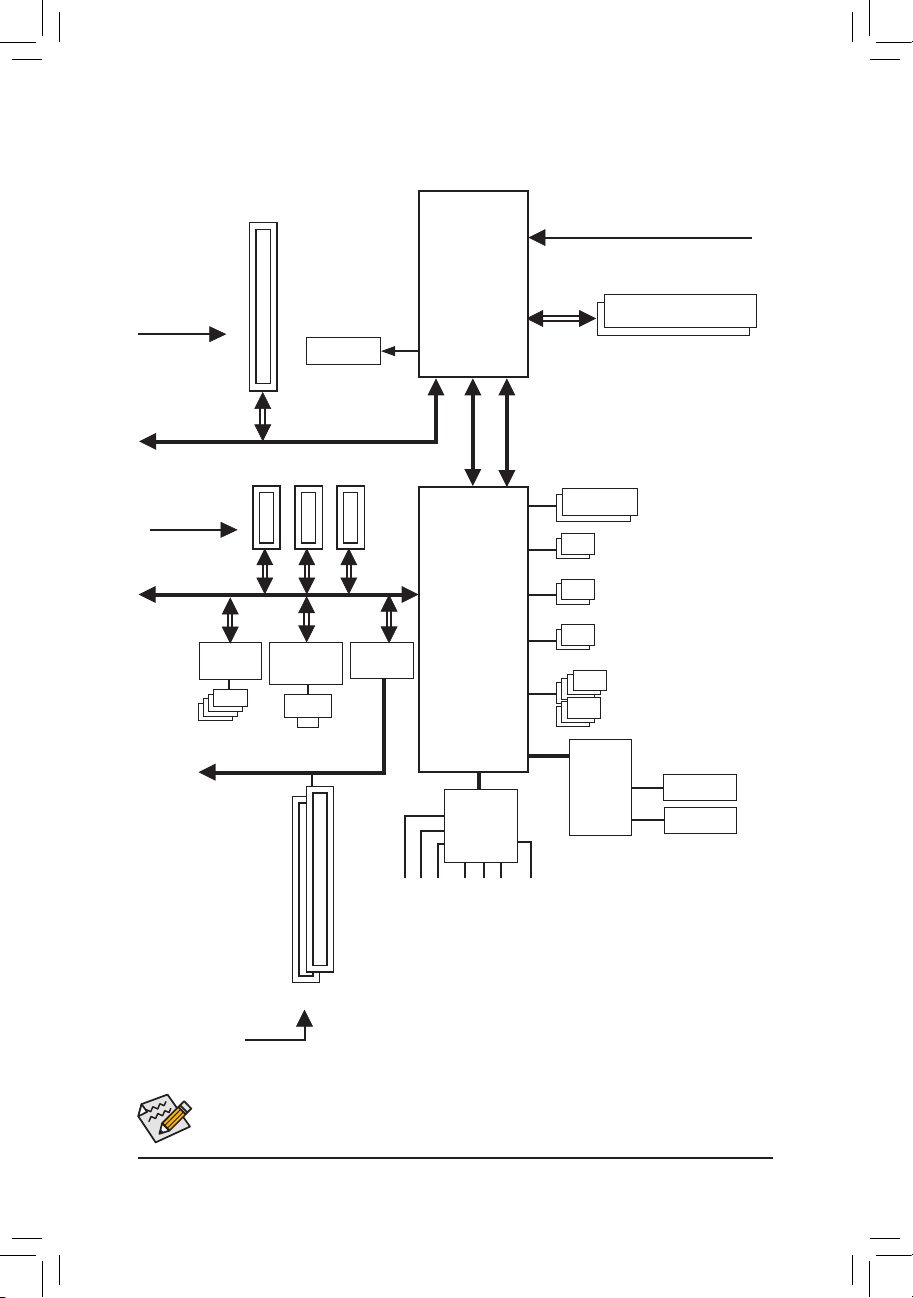
GA-H81.AMP-UP Motherboard Block Diagram
1 PCI Express x16
PCIe CLK
(100 MHz)
PCI Express Bus
PCIe CLK
(100 MHz)
PCI Express Bus
VIA®
VL805
4 USB 3.0/2.0
x16
3 PCI Express x1
x1
x1
PCI Bus
x1 x1
x1
Realtek®
GbE LAN
RJ45
LAN
HDMI
PCIe to PCI
Bridge
CPU CLK+/- (100 MHz)
LGA1150
CPU
DDR3 1600/1333 MHz
Dual Channel Memory
FDI
DMI 2.0
Dual BIOS
2 SATA 6Gb/s
2 SATA 3Gb/s
Intel® H81
x1
2 USB 3.0/2.0
7 USB 2.0/1.1
LPC
Bus
iTE®
Super I/O
COM
CODEC
PS/2 KB/Mouse
MIC
Line In
Line Out
S/PDIF Out
Side Speaker Out
Rear Speaker Out
PCI CLK
2 PCI
(33 MHz)
Center/Subwoofer Speaker Out
For detailed product information/limitation(s), refer to "1-2 Product Specications."
- 5 -

Chapter 1 Hardware Installation
1-1 Installation Precautions
The motherboard contains numerous delicate electronic circuits and components which can become
damaged as a result of electrostatic discharge (ESD). Prior to installation, carefully read the user's
manual and follow these procedures:
• Prior to installation, make sure the chassis is suitable for the motherboard.
• Prior to installation, do not remove or break motherboard S/N (Serial Number) sticker or
warranty sticker provided by your dealer. These stickers are required for warranty validation.
• Always remove the AC power by unplugging the power cord from the power outlet before
installing or removing the motherboard or other hardware components.
• When connecting hardware components to the internal connectors on the motherboard, make
sure they are connected tightly and securely.
• When handling the motherboard, avoid touching any metal leads or connectors.
• It is best to wear an electrostatic discharge (ESD) wrist strap when handling electronic
components such as a motherboard, CPU or memory. If you do not have an ESD wrist strap,
keep your hands dry and rst touch a metal object to eliminate static electricity.
• Prior to installing the motherboard, please have it on top of an antistatic pad or within an
electrostatic shielding container.
• Before unplugging the power supply cable from the motherboard, make sure the power supply
has been turned off.
• Before turning on the power, make sure the power supply voltage has been set according to
the local voltage standard.
• Before using the product, please verify that all cables and power connectors of your hardware
components are connected.
• To prevent damage to the motherboard, do not allow screws to come in contact with the
motherboard circuit or its components.
• Make sure there are no leftover screws or metal components placed on the motherboard or
within the computer casing.
• Do not place the computer system on an uneven surface.
• Do not place the computer system in a high-temperature environment.
• Turning on the computer power during the installation process can lead to damage to system
components as well as physical harm to the user.
• If you are uncertain about any installation steps or have a problem related to the use of the
product, please consult a certied computer technician.
- 6 -
1-2 ProductSpecications
CPU Support for Intel® Core™ i7 processors/Intel® Core™ i5 processors/
Intel® Core™ i3 processors/Intel® Pentium® processors/
Intel® Celeron® processors in the LGA1150 package
(Go to GIGABYTE's website for the latest CPU support list.)
L3 cache varies with CPU
Chipset Intel® H81 Express Chipset
Memory 2 x 1.5V DDR3 DIMM sockets supporting up to 16 GB of system memory
Onboard
Graphics
Audio Realtek® ALC898 codec
LAN Realtek® GbE LAN chip (10/100/1000 Mbit)
Expansion Slots 1 x PCI Express x16 slot, running at x16
Storage Interface Chipset:
USB Chipset:
Internal
Connectors
* Due to a Windows 32-bit operating system limitation, when more than 4 GB of
physical memory is installed, the actual memory size displayed will be less than the
size of the physical memory installed.
Dual channel memory architecture
Support for DDR3 1600/1333 MHz memory modules
Support for non-ECC memory modules
Support for Extreme Memory Prole (XMP) memory modules
(Go to GIGABYTE's website for the latest supported memory speeds and memory
modules.)
Integrated Graphics Processor:
- 1 x HDMI port, supporting a maximum resolution of 4096x2160
* Support for HDMI 1.4a version.
- Maximum shared memory of 1 GB
High Denition Audio
2/4/5.1/7.1-channel
Support for S/PDIF Out
3 x PCI Express x1 slots
(The PCI Express slots conform to PCI Express 2.0 standard.)
2 x PCI slots
- 2 x SATA 6Gb/s connectors (SATA3 0/1)
- 2 x SATA 3Gb/s connectors (SATA2 2/3)
- 2 x USB 3.0/2.0 ports (available through the internal USB header)
- 7 x USB 2.0/1.1 ports (3 ports on the back panel, 4 ports available through
the internal USB headers)
VIA® VL805 chip:
- 4 x USB 3.0/2.0 ports on the back panel
1 x 24-pin ATX main power connector
1 x 8-pin ATX 12V power connector
2 x SATA 6Gb/s connectors
2 x SATA 3Gb/s connectors
- 7 -
Internal
Connectors
1 x CPU fan header
3 x system fan headers
1 x front panel header
1 x front panel audio header
1 x USB 3.0/2.0 header
2 x USB 2.0/1.1 headers
1 x serial port header
1 x Clear CMOS jumper
2 x gain control switches
Back Panel
Connectors
1 x PS/2 keyboard/mouse port
1 x HDMI port
4 x USB 3.0/2.0 ports
3 x USB 2.0/1.1 ports
1 x RJ-45 port
1 x optical S/PDIF Out connector
5 x audio jacks (Center/Subwoofer Speaker Out, Rear Speaker Out, Line In,
Line Out, Mic In)
I/O Controller iTE® I/O Controller Chip
Hardware
Monitor
System voltage detection
CPU/System temperature detection
CPU/System fan speed detection
CPU/System overheating warning
CPU/System fan fail warning
CPU/System fan speed control
* Whether the fan speed control function is supported will depend on the cooler you
install.
BIOS 2 x 64 Mbit ash
Use of licensed AMI EFI BIOS
Support for DualBIOS
PnP 1.0a, DMI 2.0, SM BIOS 2.6, ACPI 2.0a
Unique Features Support for Q-Flash
Support for Xpress Install
Support for APP Center
* Available applications in APP Center may differ by motherboard model. Supported
fun ction s of each app li catio n may also differ dep ending on motherbo ard
specications.
- @BIOS
- EasyTune
- EZ Setup
- USB Blocker
- Smart Recovery 2
- Smart TimeLock
Support for ON/OFF Charge
Bundled
Software
Norton® Internet Security (OEM version)
™
- 8 -
Operating
System
Support for Windows 8.1/8/7
* If you plan to install Windows 8.1, please download the latest drivers from
GIGABYTE's website.
Form Factor ATX Form Factor; 30.4cm x 19cm
* GIGABYTE reserves the right to make any changes to the product specications and product-related information without
prior notice.
* Please visit the
for the software listed in the "Unique Features" and "Bundled Software" columns.
Support & Downloads\Utility
page on GIGABYTE's website to check the supported operating system(s)
1-3 Installing the CPU
Read the following guidelines before you begin to install the CPU:
• Make sure that the motherboard supports the CPU.
(Go to GIGABYTE's website for the latest CPU support list.)
• Always turn off the computer and unplug the power cord from the power outlet before installing the
CPU to prevent hardware damage.
• Locate the pin one of the CPU. The CPU cannot be inserted if oriented incorrectly. (Or you may
locate the notches on both sides of the CPU and alignment keys on the CPU socket.)
• Apply an even and thin layer of thermal grease on the surface of the CPU.
• Do not turn on the computer if the CPU cooler is not installed, otherwise overheating and damage
of the CPU may occur.
• Set the CPU host frequency in accordance with the CPU specications. It is not recommended
that the system bus frequency be set beyond hardware specications since it does not meet the
standard requirements for the peripherals. If you wish to set the frequency beyond the standard
specications, please do so according to your hardware specications including the CPU, graphics
card, memory, hard drive, etc.
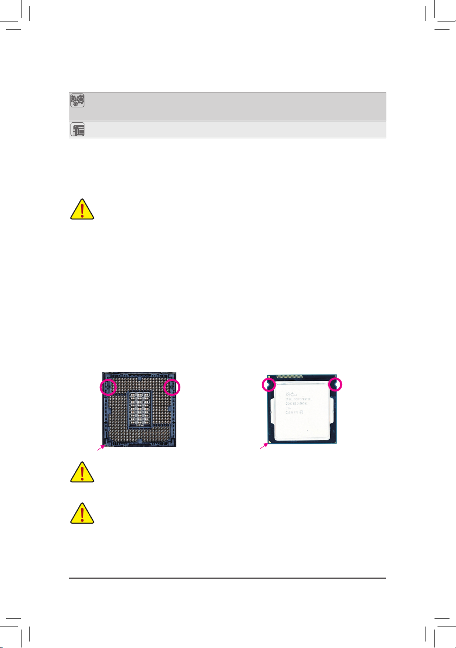
Installing the CPU
Locate the alignment keys on the motherboard CPU socket and the notches on the CPU.
LGA1150 CPU Socket
LGA1150 CPU
Key
Alignment KeyAlignment
Pin One Corner of the CPU Socket
Notch
Triangle Pin One Marking on the CPU
Do not remove the CPU socket cover before inserting the CPU. It may pop off from the load plate
automatically during the process of re-engaging the lever after you insert the CPU.
1-4 Installing the Memory
Read the following guidelines before you begin to install the memory:
• Make sure that the motherboard supports the memory. It is recommended that memory of the
same capacity, brand, speed, and chips be used.
(Go to GIGABYTE's website for the latest supported memory speeds and memory modules.)
• Always turn off the computer and unplug the power cord from the power outlet before installing the
memory to prevent hardware damage.
• Memory modules have a foolproof design. A memory module can be installed in only one direction.
If you are unable to insert the memory, switch the direction.
- 9 -
Notch
DualChannelMemoryConguration
This motherboard provides two DDR3 memory sockets and supports Dual Channel Technology. After the memory
is installed, the BIOS will automatically detect the specications and capacity of the memory. Enabling Dual
Channel memory mode will double the original memory bandwidth.
The two DDR3 memory sockets are divided into two channels and each channel has one memory socket as
following:
Channel A: DDR3_1
Channel B: DDR3_2
Due to CPU limitations, read the following guidelines before installing the memory in Dual Channel mode.
1. Dual Channel mode cannot be enabled if only one DDR3 memory module is installed.
2. When enabling Dual Channel mode with two memory modules, it is recommended that memory of
the same capacity, brand, speed, and chips be used for optimum performance.
1-5 Installing an Expansion Card
Read the following guidelines before you begin to install an expansion card:
• Make sure the motherboard supports the expansion card. Carefully read the manual that came
with your expansion card.
• Always turn off the computer and unplug the power cord from the power outlet before installing an
expansion card to prevent hardware damage.
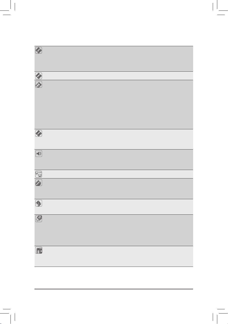
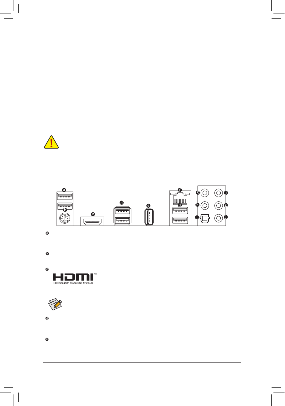
1-6 Back Panel Connectors
USB 2.0/1.1 Port
The USB port supports the USB 2.0/1.1 specication. Use this port for USB devices such as a USB
keyboard/mouse, USB printer, USB ash drive and etc.
PS/2 Keyboard/Mouse Port
Use this port to connect a PS/2 mouse or keyboard.
HDMI Port
The HDMI port is HDCP compliant and supports Dolby True HD and DTS HD
Master Audio formats. It also supports up to 192KHz/24bit 8-channel LPCM
audio output. You can use this port to connect your HDMI-supported monitor. The maximum supported
resolution is 4096x2160, but the actual resolutions supported are dependent on the monitor being used.
After installing the HDMI device, make sure to set the default sound playback device to HDMI.
USB 3.0/2.0 Port
The USB 3.0 port supports the USB 3.0 specication and is compatible to the USB 2.0/1.1 specication.
Use this port for USB devices such as a USB keyboard/mouse, USB printer, USB ash drive and etc.
USB 2.0/1.1 Port
The USB port supports the USB 2.0/1.1 specication. You can connect a USB DAC to this port or use
this port for USB devices such as a USB keyboard/mouse, USB printer, USB ash drive and etc.
- 10 -
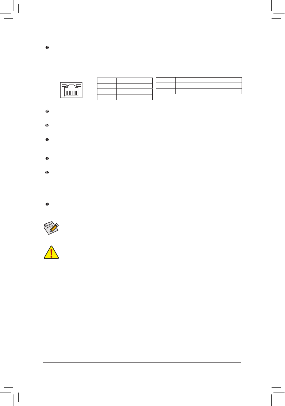
RJ-45 LAN Port
The Gigabit Ethernet LAN port provides Internet connection at up to 1 Gbps data rate. The following
describes the states of the LAN port LEDs.
Connection/
Speed LED
Activity LED
LAN Port
Connection/Speed LED:
State Description
Orange 1 Gbps data rate
Green 100 Mbps data rate
Off 10 Mbps data rate
Activity LED:
State Description
Blinking Data transmission or receiving is occurring
Off No data transmission or receiving is occurring
Center/Subwoofer Speaker Out Jack
Use this audio jack to connect center/subwoofer speakers in a 5.1/7.1-channel audio conguration.
Rear Speaker Out
This jack can be used to connect front speakers in a 4/5.1/7.1-channel audio conguration.
Optical S/PDIF Out Connector
This connector provides digital audio out to an external audio system that supports digital optical audio.
Before using this feature, ensure that your audio system provides an optical digital audio in connector.
Line In
The default line in jack. Use this audio jack for line in devices such as an optical drive, walkman, etc.
Line Out
The default line out jack. This jack supports audio amplifying function. For better sound quality, it is
recommended that you connect your headphone/speaker to this jack. Use this audio jack for a headphone
or 2-channel speaker. This jack can be used to connect front speakers in a 4/5.1/7.1-channel audio
conguration.
Mic In
The default Mic in jack. Microphones must be connected to this jack.
The audio jacks can be recongured to perform different functions via the audio software (supported
functions for each jack may vary based on hardware specication). Only microphones still MUST be
connected to the default Mic in jack.
• When removing the cable connected to a back panel connector, rst remove the cable from your
device and then remove it from the motherboard.
• When removing the cable, pull it straight out from the connector. Do not rock it side to side to prevent
an electrical short inside the cable connector.
- 11 -
 Loading...