

Gigabyte GA-H67MA-UD2H-B3 (rev. 1.1) User Manual [ru]

GA-H67MA-UD2H-B3
LGA1155 socket motherboard for Intel® Core™ i7 processors/
Intel® Core™ i5 processors/Intel® Core™ i3 processors/
Intel® Pentium® processors/Intel® Celeron® processors
User's Manual
Rev. 1101
12ME-H67U2HB-1101R
Jan. 05, 2011
Motherboard
GA-H67MA-UD2H-B3
Motherboard
GA-H67MA-UD2H-B3
Jan. 05, 2011
Copyright
©
2011 GIGA-BYTE TECHNOLOGY CO., LTD. All rights reserved.
The trademarks mentioned in this manual are legally registered to their respective owners.
Disclaimer
Information in this manual is protected by copyright laws and is the property of GIGABYTE.
Changes to the specications and features in this manual may be made by GIGABYTE with-
out prior notice. No part of this manual may be reproduced, copied, translated, transmitted, or
published in any form or by any means without GIGABYTE's prior written permission.
Documentation Classications
In order to assist in the use of this product, GIGABYTE provides the following types of documentations:
For quick set-up of the product, read the Quick Installation Guide included with the product.
For detailed product information, carefully read the User's Manual.
For product-related information, check on our website at:
http://www.gigabyte.com
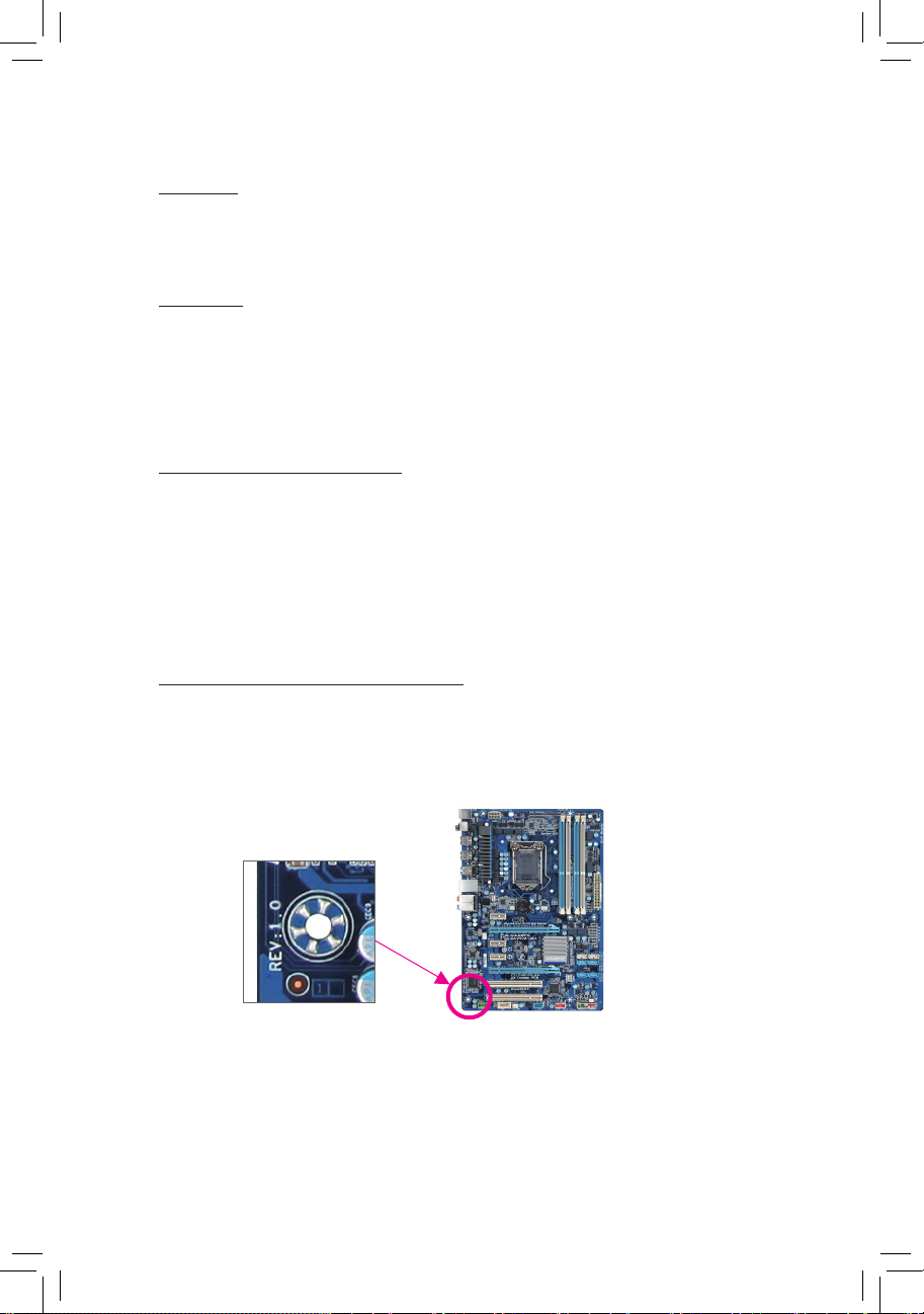
Identifying Your Motherboard Revision
The revision number on your motherboard looks like this: "REV: X.X." For example, "REV: 1.0"
means the revision of the motherboard is 1.0. Check your motherboard revision before updating
motherboard BIOS, drivers, or when looking for technical information.
Example:

- 4 -
Table of Contents
Box Contents ...................................................................................................................6
Optional Items .................................................................................................................6
GA-H67MA-UD2H-B3 Motherboard Layout ....................................................................7
GA-H67MA-UD2H-B3 Motherboard Block Diagram ........................................................8
Chapter 1 Hardware Installation .....................................................................................9
1-1 Installation Precautions ....................................................................................9
1-2 Product Specications .................................................................................... 10
1-3 Installing the CPU and CPU Cooler ............................................................... 13
1-3-1 Installing the CPU ...................................................................................................13
1-3-2 Installing the CPU Cooler .......................................................................................15
1-4 Installing the Memory .....................................................................................16
1-4-1 Dual Channel Memory Conguration .....................................................................16
1-4-2 Installing a Memory ...............................................................................................17
1-5 Installing an Expansion Card ......................................................................... 18
1-6 Back Panel Connectors .................................................................................. 19
1-7 Internal Connectors ........................................................................................ 22
Chapter 2 BIOS Setup ..................................................................................................31
2-1 Startup Screen ............................................................................................... 32
2-2 The Main Menu .............................................................................................. 33
2-3 MB Intelligent Tweaker(M.I.T.) ........................................................................ 35
2-4 Standard CMOS Features .............................................................................. 43
2-5 Advanced BIOS Features .............................................................................. 45
2-6 Integrated Peripherals .................................................................................... 47
2-7 Power Management Setup ............................................................................. 50
2-8 PC Health Status ............................................................................................ 52
2-9 Load Fail-Safe Defaults .................................................................................. 54
2-10 Load Optimized Defaults ................................................................................ 54
2-11 Set Supervisor/User Password ...................................................................... 55
2-12 Save & Exit Setup .......................................................................................... 56
2-13 Exit Without Saving ........................................................................................ 56

- 5 -
Chapter 3 Drivers Installation ........................................................................................57
3-1 Installing Chipset Drivers ............................................................................... 57
3-2 Application Software ...................................................................................... 58
3-3 Technical Manuals .......................................................................................... 58
3-4 Contact ........................................................................................................... 59
3-5 System ........................................................................................................... 59
3-6 Download Center ........................................................................................... 60
3-7 New Utilities ................................................................................................... 60
Chapter 4 Unique Features ...........................................................................................61
4-1 Xpress Recovery2 .......................................................................................... 61
4-2 BIOS Update Utilities ..................................................................................... 64
4-2-1 Updating the BIOS with the Q-Flash Utility .............................................................64
4-2-2 Updating the BIOS with the @BIOS Utility .............................................................67
4-3 EasyTune 6 .................................................................................................... 68
4-4 Dynamic Energy Saver
™
2 .............................................................................. 69
4-5 Q-Share .......................................................................................................... 71
4-6 Smart 6™ ....................................................................................................... 72
4-7 Auto Green ..................................................................................................... 76
4-8 eXtreme Hard Drive (X.H.D) .......................................................................... 77
4-9 Cloud OC ....................................................................................................... 78
Chapter 5 Appendix ......................................................................................................79
5-1 Conguring SATA Hard Drive(s) ..................................................................... 79
5-1-1 Conguring SATA Controllers ................................................................................79
5-1-2 Installing the SATA RAID/AHCI Driver and Operating System ...............................87
5-2 Conguring Audio Input and Output ............................................................... 91
5-2-1 Conguring 2/4/5.1/7.1-Channel Audio ...................................................................91
5-2-2 Conguring S/PDIF Out ..........................................................................................93
5-2-3 Enabling the Dolby Home Theater Function ...........................................................94
5-2-4 Conguring Microphone Recording ........................................................................95
5-2-5 Using the Sound Recorder .....................................................................................97
5-3 Troubleshooting.............................................................................................. 98
5-3-1 Frequently Asked Questions ..................................................................................98
5-3-2 Troubleshooting Procedure ....................................................................................99
- 6 -
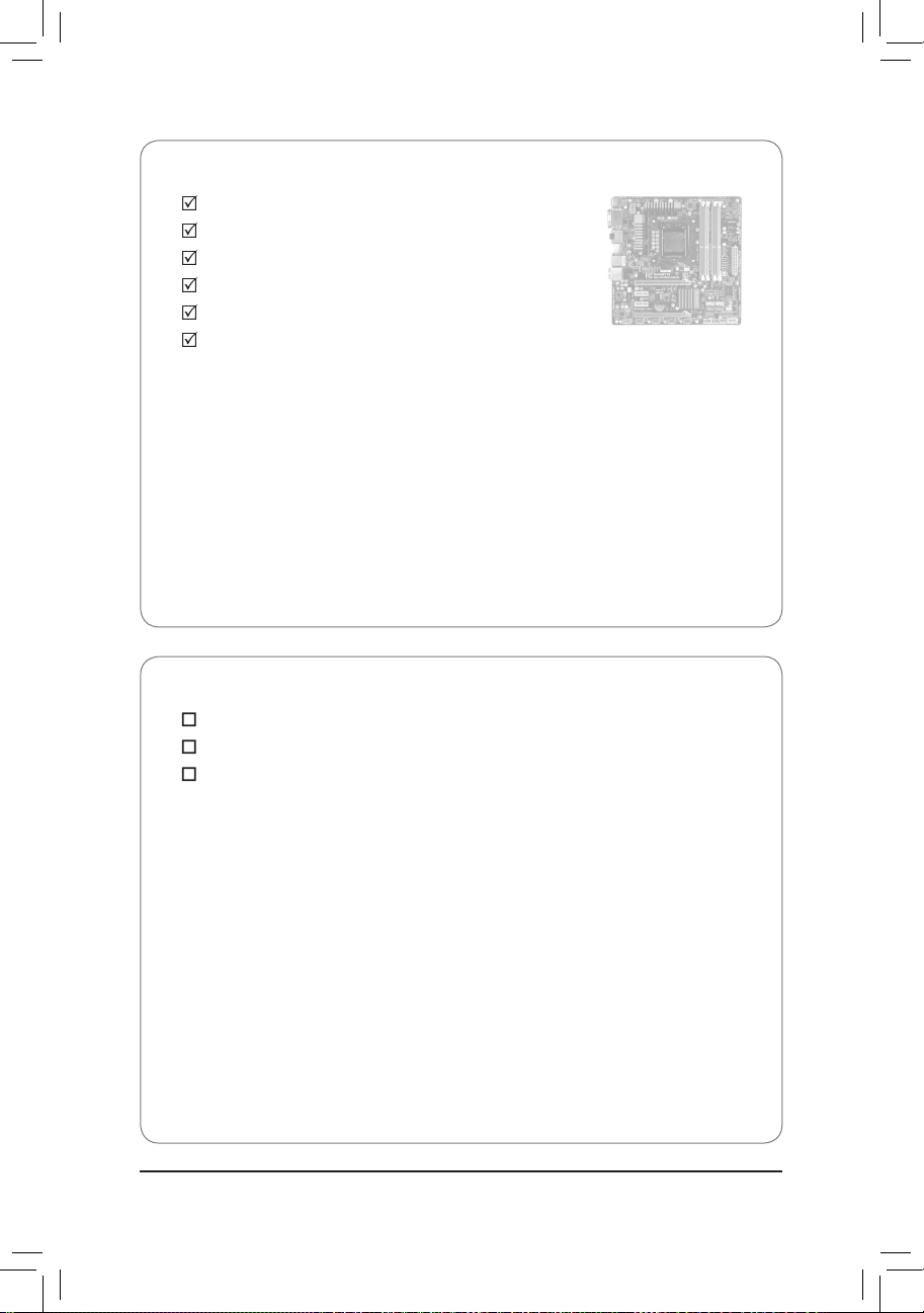
Box Contents
GA-H67MA-UD2H-B3 motherboard
Motherboard driver disk
User's Manual
Quick Installation Guide
Four SATA cables
I/O Shield
Optional Items
2-port USB 2.0 bracket (Part No. 12CR1-1UB030-5*R)
2-port SATA power cable (Part No. 12CF1-2SERPW-0*R)
COM port cable (Part No. 12CF1-1CM001-3*R)
•
The box contents above are for reference only and the actual items shall depend on the product package you obtain.
The box contents are subject to change without notice.
•
The motherboard image is for reference only.
- 7 -
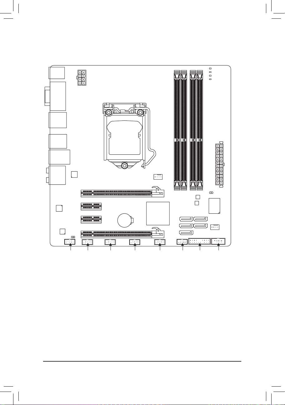
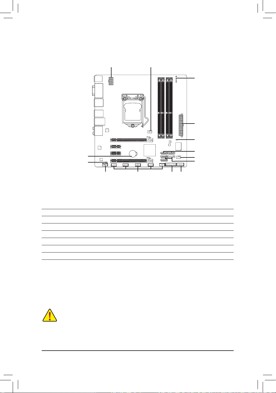
GA-H67MA-UD2H-B3 Motherboard Layout
CPU_FAN
LGA1155
ATX
F_AUDIO
AUDIO
M_BIOS
PCIEX4
DDR3_2
DDR3_1
DDR3_4
DDR3_3
BAT
F_PANEL
ATX_12V_2X4
Intel® H67
SATA3_1
SATA2_3
SATA3_0
SATA2_2
SATA2_4
CODEC
B_BIOS
F_USB2
VGA_DVI
USB30_LAN
PCIEX16
SPDIF_O
F_USB1
Realtek
RTL8111E
PHASE LED
DP_HDMI_SPDIF
iTE
IT8728
KB_USB
USB_ESATA
PCIEX1_2
GA-H67MA-UD2H-B3
CLR_CMOS
F_USB3F_USB4 COM
SYS_FAN
F_USB5
PCIEX1_1
Renesas
D720200
- 8 -
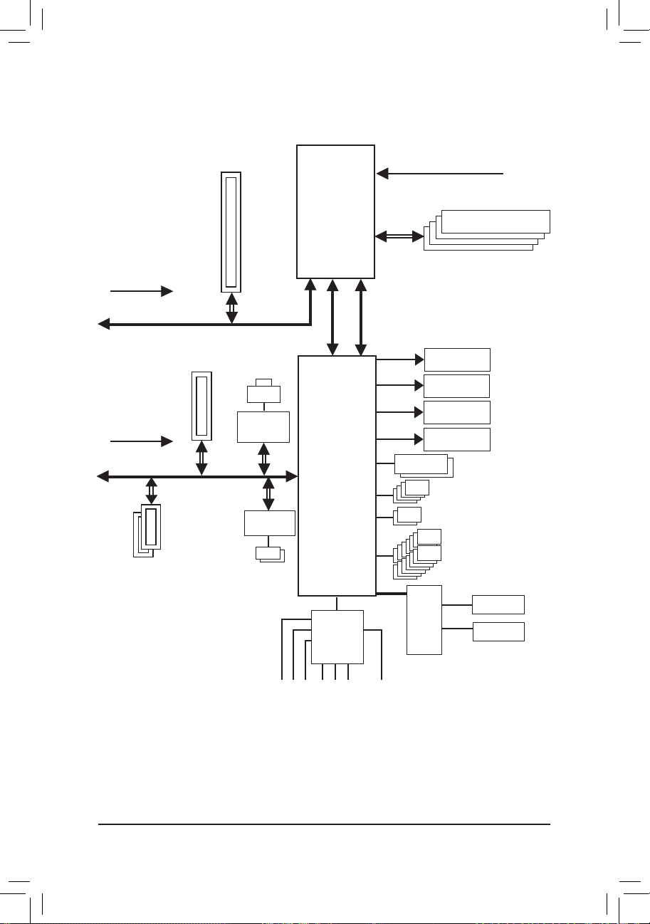
GA-H67MA-UD2H-B3 Motherboard Block Diagram
Center/Subwoofer Speaker Out
Line Out
MIC
Line In
S/PDIF Out
Side Speaker Out
Surround Speaker Out
CODEC
PS/2 KB/Mouse
LGA1155
CPU
Intel® H67
PCIe CLK
(100 MHz)
PCI Express Bus
CPU CLK+/- (100 MHz)
1 PCI Express x16
Dual BIOS
COM Port
14 USB 2.0/1.1
LPC
Bus
DDR3 1333/1066/800 MHz
x1
LAN
RJ45
x4
1 PCI Express x4
PCI Express Bus
x16
PCIe CLK
(100 MHz)
D-Sub
DVI-D
HDMI
x1
Renesas
D720200
Realtek
RTL8111E
2 USB 3.0/2.0
DisplayPort
Dual Channel Memory
iTE
IT8728
2 SATA 6Gb/s
4 SATA 3Gb/s
x1
2 PCI Express x1
DMI Interface
FDI Interface

- 9 - Hardware Installation
1-1 Installation Precautions
The motherboard contains numerous delicate electronic circuits and components which can
become damaged as a result of electrostatic discharge (ESD). Prior to installation, carefully read
the user's manual and follow these procedures:
•Prior to installation, do not remove or break motherboard S/N (Serial Number) sticker or
warranty sticker provided by your dealer. These stickers are required for warranty validation.
•Always remove the AC power by unplugging the power cord from the power outlet before
installing or removing the motherboard or other hardware components.
•When connecting hardware components to the internal connectors on the motherboard,
make sure they are connected tightly and securely.
•When handling the motherboard, avoid touching any metal leads or connectors.
•It is best to wear an electrostatic discharge (ESD) wrist strap when handling electronic com-
ponents such as a motherboard, CPU or memory. If you do not have an ESD wrist strap,
keep your hands dry and rst touch a metal object to eliminate static electricity.
•
Prior to installing the motherboard, please have it on top of an antistatic pad or within an
electrostatic shielding container.
•Before unplugging the power supply cable from the motherboard, make sure the power sup-
ply has been turned off.
•Before turning on the power, make sure the power supply voltage has been set according to
the local voltage standard.
•Before using the product, please verify that all cables and power connectors of your hard-
ware components are connected.
•To prevent damage to the motherboard, do not allow screws to come in contact with the
motherboard circuit or its components.
•Make sure there are no leftover screws or metal components placed on the motherboard or
within the computer casing.
•Do not place the computer system on an uneven surface
.
•Do not place the computer system in a high-temperature environment.
•Turning on the computer power during the installation process can lead to damage to sys-
tem components as well as physical harm to the user.
•If you are uncertain about any installation steps or have a problem related to the use of the
product, please consult a certied computer technician.
Chapter 1 Hardware Installation
- 10 -Hardware Installation
1-2 Product Specications
CPU Support for Intel® Core™ i7 processors/Intel® Core™ i5 processors/
Intel® Core™ i3 processors/Intel® Pentium® processors/Intel® Celeron® processors in the LGA1155 package
(Go to GIGABYTE's website for the latest CPU support list.)
L3 cache varies with CPU
Chipset
Intel® H67 Express Chipset
Memory 4 x 1.5V DDR3 DIMM sockets supporting up to 32 GB of system memory
* Due to Windows 32-bit operating system limitation, when more than 4 GB of physical
memory is installed, the actual memory size displayed will be less than 4 GB.
Dual channel memory architecture
Support for DDR3 1333/1066/800 MHz memory modules
Support for non-ECC memory modules
(Go to GIGABYTE's website for the latest supported memory speeds and memory modules.)
Onboard Graphics Integrated in the Chipset:
- 1 x D-Sub port
- 1 x DVI-D port, supporting a maximum resolution of 1920x1200
* The DVI-D port does not support D-Sub connection by adapter.
- 1 x HDMI port, supporting a maximum resolution of 1920x1200
- 1 x DisplayPort
(To use the onboard DisplayPort, HDMI, DVI-D, and D-Sub ports, you must
install an Intel CPU with integrated graphics.)
Audio
Realtek ALC892/889 codec
High Denition Audio
2/4/5.1/7.1-channel
Support for Dolby® Home Theater
Support for S/PDIF Out
LAN
1 x Realtek RTL8111E chip (10/100/1000 Mbit)
Expansion Slots 1 x PCI Express x16 slot, running at x16 (PCIEX16)
* For optimum performance, if only one PCI Express graphics card is to be installed,
be sure to install it in the PCIEX16 slot.
1 x PCI Express x16 slot, running at x4 (PCIEX4)
2 x PCI Express x1 slots
(All PCI Express slots conform to PCI Express 2.0 standard.)
Multi-Graphics
Support for ATI CrossFireX™
Technology
* The PCIEX16 slot operates at up to x8 mode when ATI CrossFireX™ is enabled
- 11 - Hardware Installation
Storage Interface Chipset:
- 2 x SATA 6Gb/s connectors (SATA3_0~SATA3_1) supporting up to 2 SATA
6Gb/s devices
- 3 x SATA 3Gb/s connectors (SATA2_2~SATA2_4) supporting up to 3 SATA
3Gb/s devices
-
1 x eSATA 3Gb/s connector on the back panel supporting up to 1 SATA 3Gb/s
device
- Support for SATA RAID 0, RAID 1, RAID 5, and RAID 10
* When a RAID set is built across the SATA 6Gb/s and SATA 3Gb/s channels, the
system performance of the RAID set may vary depending on the devices being connected.
USB Chipset:
- Up to 14 USB 2.0/1.1 ports (4 on the back panel, 10 via the USB brackets
connected to the internal USB headers)
Renesas D720200 chip:
- Up to 2 USB 3.0/2.0 ports on the back panel.
Internal
1 x 24-pin ATX main power connector
Connectors 1 x 8-pin ATX 12V power connector
5 x SATA 3Gb/s connectors
1 x CPU fan header
1 x system fan header
1 x front panel header
1 x front panel audio header
1 x S/PDIF Out header
5 x USB 2.0/1.1 headers
1 x serial port header
1 x clearing CMOS jumper
Back Panel 1 x PS/2 keyboard/mouse port
Connectors
1 x D-Sub port
1 x DVI-D port
1 x HDMI port
1 x DisplayPort
1 x optical S/PDIF Out connector
4 x USB 2.0/1.1 ports
2 x USB 3.0/2.0 ports
1 x eSATA 3Gb/s connector
1 x RJ-45 port
6 x audio jacks (Center/Subwoofer Speaker Out/Rear Speaker Out/
Side Speaker Out/Line In/Line Out/Microphone)
- 12 -Hardware Installation
I/O Controller iTE IT8728 chip
Hardware Monitor System voltage detection
CPU/System temperature detection
CPU/System fan speed detection
CPU overheating warning
CPU/System fan fail warning
CPU/System fan speed control
* Whether the CPU/system fan speed control function is supported will depend on the
CPU/system cooler you install.
BIOS 2 x 32 Mbit ash
Use of licensed AWARD BIOS
Support for DualBIOS
™
PnP 1.0a, DMI 2.0, SM BIOS 2.4, ACPI 1.0b
Unique Features Support for @BIOS
Support for Q-Flash
Support for Xpress BIOS Rescue
Support for Download Center
Support for Xpress Install
Support for Xpress Recovery2
Support for EasyTune
* Available functions in EasyTune may differ by motherboard model.
Support for Dynamic Energy Saver™ 2
Support for Smart 6
™
Support for Auto Green
Support for eXtreme Hard Drive
Support for ON/OFF Charge
Support for Cloud OC
Support for Q-Share
Bundled Software Norton Internet Security (OEM version)
Operating System Support for Microsoft® Windows 7/Vista/XP
Form Factor Micro ATX Form Factor; 24.4cm x 24.4cm
* GIGABYTE reserves the right to make any changes to the product specications and product-related information without
prior notice.
- 13 - Hardware Installation
1-3 Installing the CPU and CPU Cooler
1-3-1 Installing the CPU
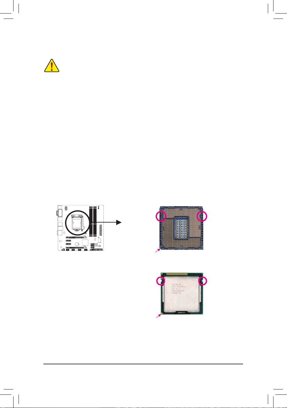
A. Locate the alignment keys on the motherboard CPU socket and the notches on the CPU.
Read the following guidelines before you begin to install the CPU:
•
Make sure that the motherboard supports the CPU.
(Go to GIGABYTE's website for the latest CPU support list.)
•
Always turn off the computer and unplug the power cord from the power outlet before installing
the CPU to prevent hardware damage.
•
Locate the pin one of the CPU. The CPU cannot be inserted if oriented incorrectly. (Or you may
locate the notches on both sides of the CPU and alignment keys on the CPU socket.)
•
Apply an even and thin layer of thermal grease on the surface of the CPU.
•
Do not turn on the computer if the CPU cooler is not installed, otherwise overheating and damage of the CPU may occur.
•
Set the CPU host frequency in accordance with the CPU specications. It is not recommended
that the system bus frequency be set beyond hardware specications since it does not meet the
standard requirements for the peripherals. If you wish to set the frequency beyond the standard
specications, please do so according to your hardware specications including the CPU, graphics card, memory, hard drive, etc.
Notch
Alignment KeyAlignment Key
Notch
LGA1155 CPU
LGA1155 CPU Socket
Pin One Corner of the CPU Socket
Triangle Pin One Marking on the CPU
- 14 -Hardware Installation
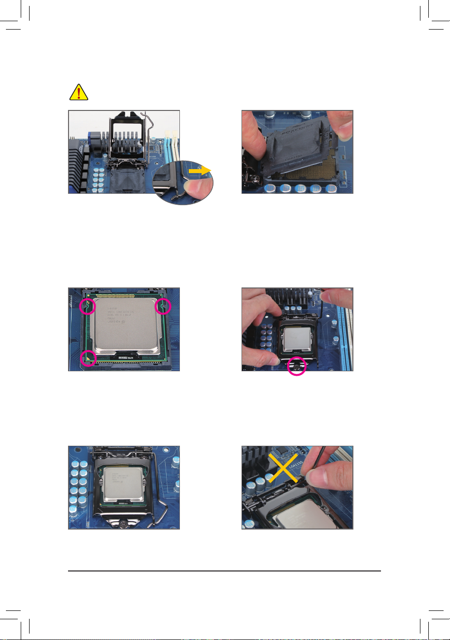
Step 1:
Gently press the CPU socket lever handle down
and away from the socket with your nger. Then
completely lift the CPU socket lever and the metal
load plate will be lifted as well.
Step 3:
Hold the CPU with your thumb and index ngers.
Align the CPU pin one marking (triangle) with the
pin one corner of the CPU socket (or you may
align the CPU notches with the socket alignment
keys) and gently insert the CPU into position.
Step 5:
Push the CPU socket lever back into its locked
position.
Step 4:
Onc e the CPU is properly inse rted, use one
hand to hold the socket lever and use the other
to lightly replace the load plate. When replacing
the load plate, make sure the front end of the
load plate is under the shoulder screw.
NOTE:
Hold the CPU socket lever by the handle, not the
lever base portion.
Step 2:
Remove the CPU socket cover as shown. Hold
your index finger down on the rear grip of the
socket cover and use your thumb to lift up the
front edge (next to the "REMOVE" mark) and
then remove the cover. (DO NOT touch socket
contacts. To protect the CPU socket, always replace the protective socket cover when the CPU
is not installed.)
B. Follow the steps below to correctly install the CPU into the motherboard CPU socket.
Before installing the CPU, make sure to turn off the computer and unplug the power cord from
the power outlet to prevent damage to the CPU.
- 15 - Hardware Installation
1-3-2 Installing the CPU Cooler
Follow the steps below to correctly install the CPU cooler on the motherboard. (The following procedure uses
Intel® boxed cooler as the example cooler.)
Use extreme care when removing the CPU cooler because the thermal grease/tape between the
CPU cooler and CPU may adhere to the CPU. Inadequately removing the CPU cooler may damage
the CPU.
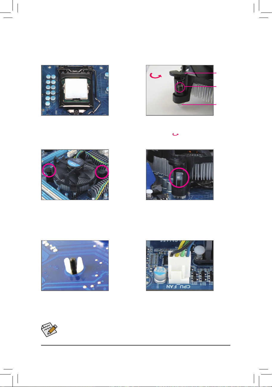
Step 1:
Apply an even and thin layer of thermal grease
on the surface of the installed CPU.
Male Push
Pin
Female
Push Pin
The Top
of Female
Push Pin
Direction of the
Arrow Sign on
the Male Push
Pin
Step 2:
Before installing the cooler, note the direction of
the arrow sign on the male push pin. (Turning the push pin along the direction of arrow is to
remove the cooler, on the contrary, is to install.)
Step 3:
Place the cooler atop the CPU, aligning the four
push pins through the pin holes on the motherboard. Push down on the push pins diagonally.
Step 4:
You should hear a "click" when pushing down
each push pin. Check that the Male and Female
push pins are joined closely. (Refer to your CPU
cooler installation manual for instructions on
installing the cooler.)
Step 5:
After the installation, check the back of the moth-
erboard. If the push pin is inserted as the picture
above shows, the installation is complete.
Step 6:
Finally, attach the power connector of the CPU
cooler to the CPU fan header (CPU_FAN) on the
motherboard.
- 16 -Hardware Installation
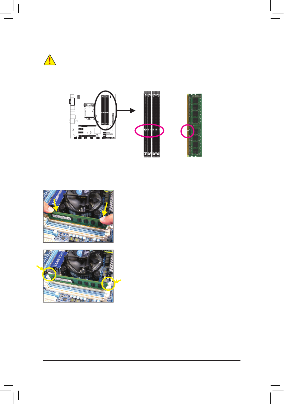
1-4-1 Dual Channel Memory Conguration
This motherboard provides four DDR3 memory sockets and supports Dual Channel Technology. After the
memory is installed, the BIOS will automatically detect the specications and capacity of the memory. Enabling Dual Channel memory mode will double the original memory bandwidth.
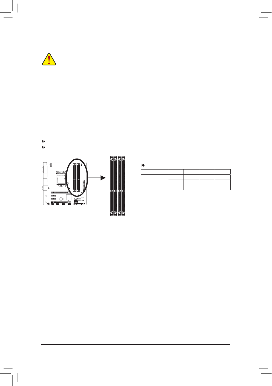
The four DDR3 memory sockets are divided into two channels and each channel has two memory sockets as
following:
Channel 0: DDR3_1, DDR3_2
Channel 1: DDR3_3, DDR3_4
1-4 Installing the Memory
Read the following guidelines before you begin to install the memory:
•
Make sure that the motherboard supports the memory. It is recommended that memory of the
same capacity, brand, speed, and chips be used.
(Go to GIGABYTE's website for the latest supported memory speeds and memory modules.)
•
Always turn off the computer and unplug the power cord from the power outlet before installing
the memory to prevent hardware damage.
•
Memory modules have a foolproof design. A memory module can be installed in only one direc-
tion. If you are unable to insert the memory, switch the direction.
DDR3_2
DDR3_1
DDR3_4
DDR3_3
Due to CPU limitations, read the following guidelines before installing the memory in Dual Channel mode.
1. Dual Channel mode cannot be enabled if only one DDR3 memory module is installed.
2. When enabling Dual Channel mode with two or four memory modules, it is recommended that
memory of the same capacity, brand, speed, and chips be used for optimum performance.
Dual Channel Memory Congurations Table
(SS=Single-Sided, DS=Double-Sided, "- -"=No Memory)
DDR3_1 DDR3_2 DDR3_3 DDR3_4
Two Modules DS/SS - - DS/SS - -
- - DS/SS - - DS/SS
Four Modules DS/SS DS/SS DS/SS DS/SS
- 17 - Hardware Installation
1-4-2 Installing a Memory
Notch
DDR3 DIMM
A DDR3 memory module has a notch, so it can only t in one direction. Follow the steps below to correctly
install your memory modules in the memory sockets.
Step 1:
Note the orientation of the memory module. Spread the retaining
clips at both ends of the memory socket. Place the memory module
on the socket. As indicated in the picture on the left, place your ngers on the top edge of the memory, push down on the memory and
insert it vertically into the memory socket.
Step 2:
The clips at both ends of the socket will snap into place when the
memory module is securely inserted.
Before installing a memory module, make sure to turn off the computer and unplug the power
cord from the power outlet to prevent damage to the memory module.
DDR3 and DDR2 DIMMs are not compatible to each other or DDR DIMMs. Be sure to install
DDR3 DIMMs on this motherboard.
- 18 -Hardware Installation
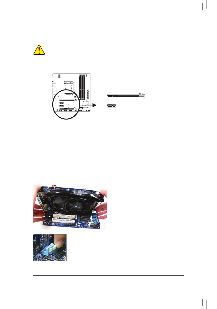
1-5 Installing an Expansion Card
Read the following guidelines before you begin to install an expansion card:
•
Make sure the motherboard supports the expansion card. Carefully read the manual that came
with your expansion card.
•
Always turn off the computer and unplug the power cord from the power outlet before installing
an expansion card to prevent hardware damage.
Follow the steps below to correctly install your expansion card in the expansion slot.
1. Locate an expansion slot that supports your card. Remove the metal slot cover from the chassis back panel.
2. Align the card with the slot, and press down on the card until it is fully seated in the slot.
3. Make sure the metal contacts on the card are completely inserted into the slot.
4. Secure the card’s metal bracket to the chassis back panel with a screw.
5. After installing all expansion cards, replace the chassis cover(s).
6. Turn on your computer. If necessary, go to BIOS Setup to make any required BIOS changes for your
expansion card(s).
7. Install the driver provided with the expansion card in your operating system.
Example: Installing and Removing a PCI Express Graphics Card:
•
Installing a Graphics Card:
Gently push down on the top edge of the card until
it is fully inserted into the PCI Express slot. Make
sure the card is securely seated in the slot and
does not rock.
PCI Express x16 Slot
•
Removing the Card:
Press the white latch at the end of the PCI Express slot to release the card and then
pull the card straight up from the slot.
PCI Express x1 Slot
- 19 - Hardware Installation
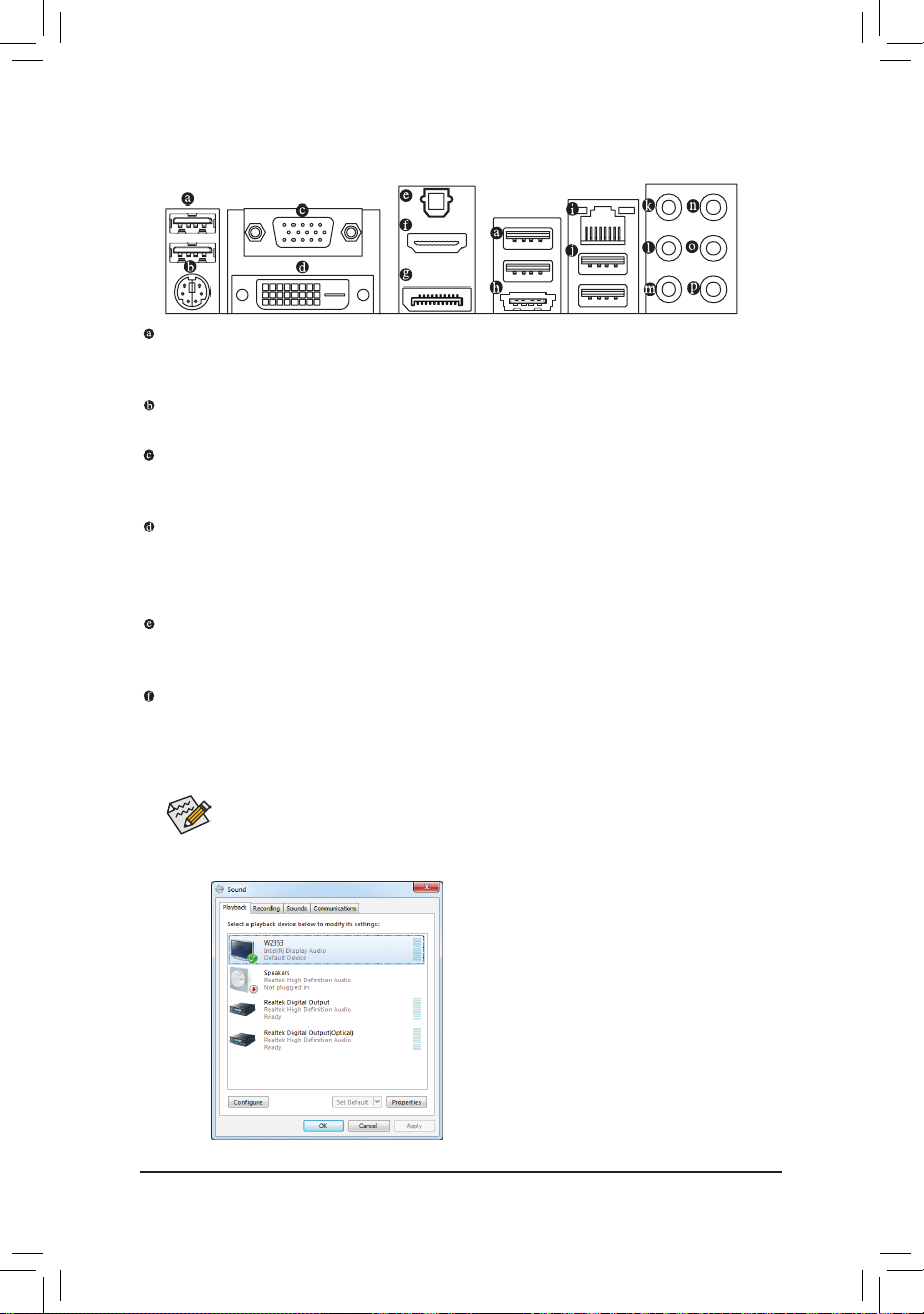
1-6 Back Panel Connectors
USB 2.0/1.1 Port
The USB port supports the USB 2.0/1.1 specication. Use this port for USB devices such as a USB key-
board/mouse, USB printer, USB ash drive and etc.
PS/2 Keyboard/Mouse Port
Use this port a PS/2 keyboard or mouse.
D-Sub Port
Note)
The D-Sub port supports a 15-pin D-Sub connector. Connect a monitor that supports D-Sub connection
to this port.
DVI-D Port
(Note)
The DVI-D port conforms to the DVI-D specication and supports a maximum resolution of 1920x1200 (the
actual resolutions supported depend on the monitor being used). Connect a monitor that supports DVI-D
connection to this port.
Optical S/PDIF Out Connector
This connector provides digital audio out to an external audio system that supports digital optical audio.
Before using this feature, ensure that your audio system provides an optical digital audio in connector.
HDMI Port
(Note)
The HDMI (High-Denition Multimedia Interface) provides an all-digital audio/video interface to transmit the
uncompressed audio/video signals and is HDCP compliant. Connect the HDMI audio/video device to this port.
The HDMI Technology can support a maximum resolution of 1920x1200 but the actual resolutions supported
depend on the monitor being used.
• After installing the HDMI device, make sure the default device for sound playback is the HDMI
device. (The item name may differ from operating system. Refer to the gure below for details.)
• Please note the HDMI audio output only supports AC3, DTS and 2-channel-LPCM formats. (AC3 and
DTS require the use of an external decoder for decoding.)
In Windows 7, select Start>Control Panel>Hardware
and Sound>Sound>Playback, set Intel(R) Display Au-
dio to the default playback device.
(Note) The DVI-D port does not support D-Sub connection by adapter.
- 20 -Hardware Installation
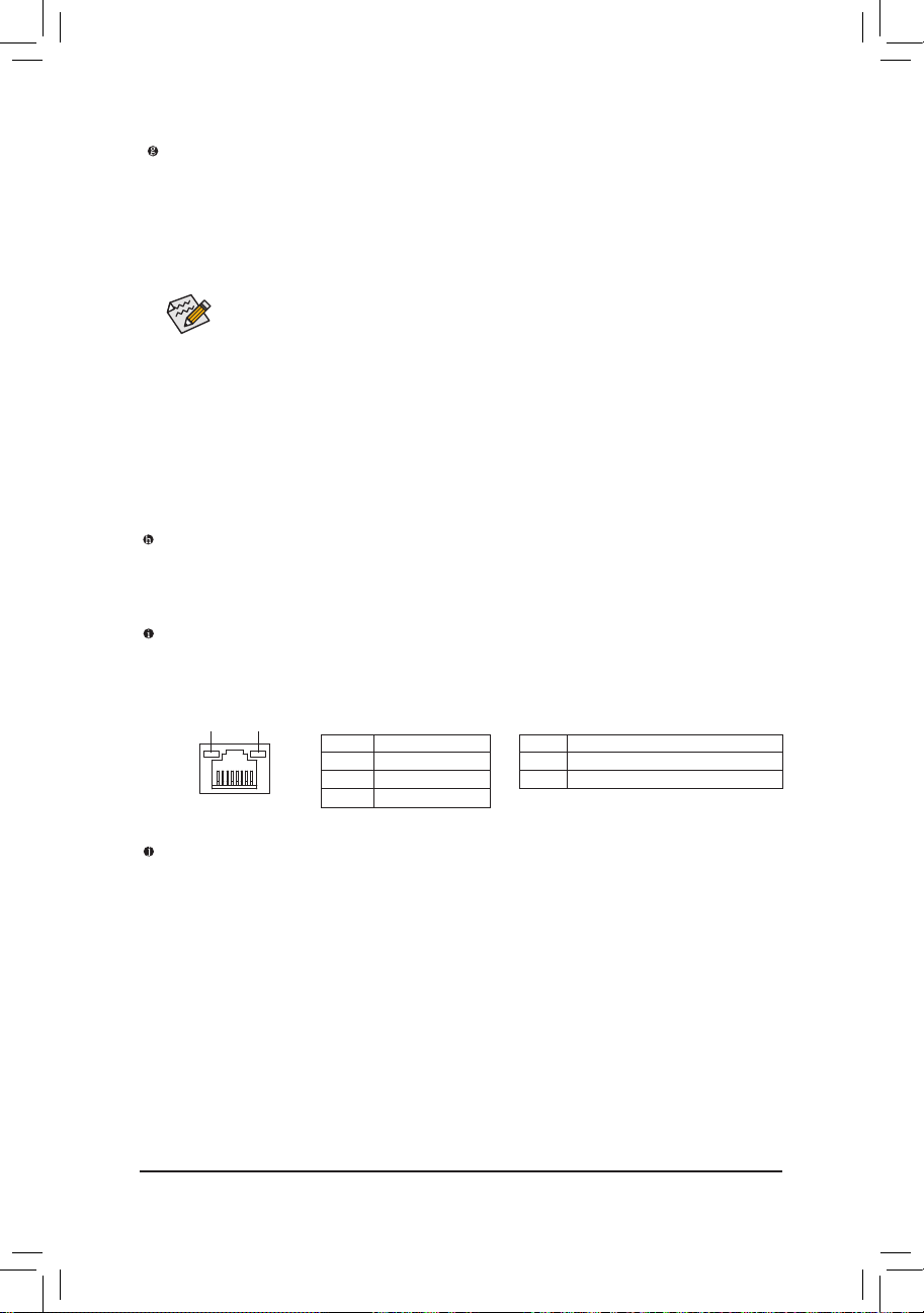
DisplayPort
(Note)
DisplayPort is one of the new generation interface technologies that delivers high quality digital imaging
and audio, supporting bi-directional audio transmition. DisplayPort can support both DPCP and HDCP
content protection mechanisms. Connect the audio/video device that supports DisplayPort to this port.
The DisplayPort Technology can support a maximum resolution of 2560x1600p but the actual resolutions
supported depend on the monitor being used.
After installing the DisplayPort device, make sure the default device for sound playback is the
DisplayPort device. (The item name may differ from operating system. For example, in Windows
7, go to Start>Control Panel>Hardware and Sound>Sound>Playback and set the DisplayPort
device as the default playback device. Refer to the HDMI settings information on the previous
page for the conguration dialog box.)
(Note) The DVI-D port does not support D-Sub connection by adapter.
eSATA 3Gb/s Port
The eSATA 3Gb/s port conforms to SATA 3Gb/s standard and is compatible with SATA 1.5Gb/s standard.
Use the port to connect an external SATA device. The H67 Chipset supports RAID function. Refer to
Chapter 5, "Conguring SATA Hard Drive(s)," for instructions on conguring a RAID array.
RJ-45 LAN Port
The Gigabit Ethernet LAN port provides Internet connection at up to 1 Gbps data rate. The following de-
scribes the states of the LAN port LEDs.
Activity LED:
State Description
Blinking Data transmission or receiving is occurring
Off No data transmission or receiving is occurring
Connection/Speed LED:
State Description
Orange 1 Gbps data rate
Green 100 Mbps data rate
Off 10 Mbps data rate
Activity LED
Connection/
Speed LED
LAN Port
USB 3.0/2.0 Port
The USB 3.0 port supports the USB 3.0 specication and is compatible to the USB 2.0/1.1 specication.
Use this port for USB devices such as a USB keyboard/mouse, USB printer, USB ash drive and etc.
Dual Monitor Congurations for the Onboard Graphics:
This motherboard provides three video output ports: D-Sub, DVI-D, and HDMI.
Dual monitor congurations are supported in operating system environment only, but not during the
BIOS Setup or POST process.
- 21 - Hardware Installation
In addition to the default speakers settings, the ~ audio jacks can be recongured to per-
form different functions via the audio software. Only microphones still MUST be connected to
the default Mic in jack ( ). Refer to the instructions on setting up a 2/4/5.1/7.1-channel audio
conguration in Chapter 5, "Conguring 2/4/5.1/7.1-Channel Audio."
•
When removing the cable connected to a back panel connector, rst remove the cable from
your device and then remove it from the motherboard.
•
When removing the cable, pull it straight out from the connector. Do not rock it side to side to
prevent an electrical short inside the cable connector.
Center/Subwoofer Speaker Out Jack (Orange)
Use this audio jack to connect center/subwoofer speakers in a 5.1/7.1-channel audio conguration.
Rear Speaker Out Jack (Black)
Use this audio jack to connect rear speakers in a 7.1-channel audio conguration.
Side Speaker Out Jack (Gray)
Use this audio jack to connect side speakers in a 4/5.1/7.1-channel audio conguration.
Line In Jack (Blue)
The default line in jack. Use this audio jack for line in devices such as an optical drive, walkman, etc.
Line Out Jack (Green)
The default line out jack. Use this audio jack for a headphone or 2-channel speaker. This jack can be
used to connect front speakers in a 4/5.1/7.1-channel audio conguration.
Mic In Jack (Pink)
The default Mic in jack. Microphones must be connected to this jack.
- 22 -Hardware Installation
1-7 Internal Connectors
Read the following guidelines before connecting external devices:
•
First make sure your devices are compliant with the connectors you wish to connect.
•
Before installing the devices, be sure to turn off the devices and your computer. Unplug the
power cord from the power outlet to prevent damage to the devices.
•
After installing the device and before turning on the computer, make sure the device cable has
been securely attached to the connector on the motherboard.
1) ATX_12V_2X4
2) ATX
3) CPU_FAN
4) SYS_FAN
5) BAT
6) SATA3_0/1
7) SATA2_2/3/4
8) F_PANEL
9) F_AUDIO
10) SPDIF_O
11) F_USB1/2/3/4/5
12) COM
13) CLR_CMOS
14) PHASE_LED
1
14
2
9 11 8
4
6
10
12
7
5
3
13
- 23 - Hardware Installation
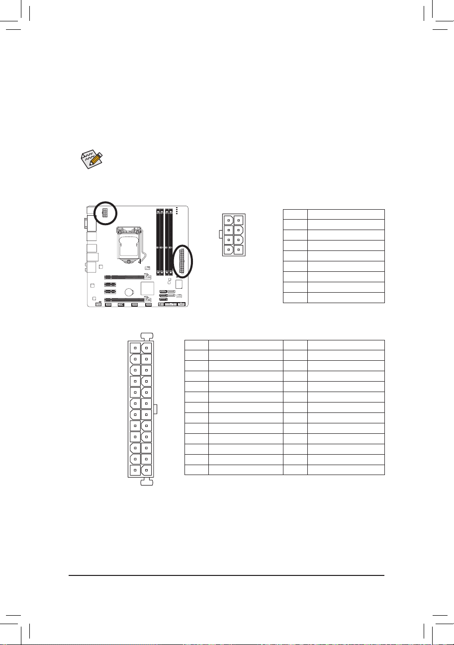
131
2412
ATX
ATX:
Pin No. Denition
13 3.3V
14 -12V
15 GND
16 PS_ON (soft On/Off)
17 GND
18 GND
19 GND
20 -5V
21 +5V
22 +5V
23 +5V (Only for 2x12-pin ATX)
24 GND (Only for 2x12-pin ATX)
Pin No. Denition
1 3.3V
2 3.3V
3 GND
4 +5V
5 GND
6 +5V
7 GND
8 Power Good
9 5VSB (stand by +5V)
10 +12V
11 +12V (Only for 2x12-pin ATX)
12 3.3V (Only for 2x12-pin ATX)
ATX_12V_2X4:
ATX_12V_2X4
5
8
1
4
1/2) ATX_12V_2X4/ATX (2x4 12V Power Connector and 2x12 Main Power Connector)
With the use of the power connector, the power supply can supply enough stable power to all the com-
ponents on the motherboard. Before connecting the power connector, rst make sure the power supply
is turned off and all devices are properly installed. The power connector possesses a foolproof design.
Connect the power supply cable to the power connector in the correct orientation. The 12V power connector mainly supplies power to the CPU. If the 12V power connector is not connected, the computer will
not start.
To meet expansion requirements, it is recommended that a power supply that can withstand
high power consumption be used (500W or greater). If a power supply is used that does not
provide the required power, the result can lead to an unstable or unbootable system.
Pin No. Denition
1 GND (Only for 2x4-pin 12V)
2 GND (Only for 2x4-pin 12V)
3 GND
4 GND
5 +12V (Only for 2x4-pin 12V)
6 +12V (Only for 2x4-pin 12V)
7 +12V
8 +12V
- 24 -Hardware Installation
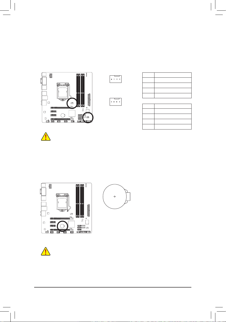
3/4) CPU_FAN/SYS_FAN (Fan Headers)
The motherboard has a 4-pin CPU fan header (CPU_FAN) and a 4-pin system fan headers (SYS_FAN).
Most fan headers possess a foolproof insertion design. When connecting a fan cable, be sure to connect
it in the correct orientation (the black connector wire is the ground wire). The motherboard supports CPU
fan speed control, which requires the use of a CPU fan with fan speed control design. For optimum heat
dissipation, it is recommended that a system fan be installed inside the chassis.
•
Be sure to connect fan cables to the fan headers to prevent your CPU, Chipset and system
from overheating. Overheating may result in damage to the CPU/Chipset or the system may
hang.
•
These fan headers are not conguration jumper blocks. Do not place a jumper cap on the
headers.
CPU_FAN:
Pin No. Denition
1 GND
2 +12V / Speed Control
3 Sense
4 Speed Control
SYS_FAN:
Pin No. Denition
1 GND
2 +12V / Speed Control
3 Sense
4 Reserve
CPU_FAN
SYS_FAN
DEBUG
PORT
1
DEBUG
PORT
1
5) BAT (Battery)
The battery provides power to keep the values (such as BIOS congurations, date, and time information)
in the CMOS when the computer is turned off. Replace the battery when the battery voltage drops to a
low level, or the CMOS values may not be accurate or may be lost.
You may clear the CMOS values by removing the battery:
1. Turn off your computer and unplug the power cord.
2. Gently remove the battery from the battery holder and wait for one
minute. (Or use a metal object like a screwdriver to touch the positive
and negative terminals of the battery holder, making them short for 5
seconds.)
3. Replace the battery.
4. Plug in the power cord and restart your computer.
•
Always turn off your computer and unplug the power cord before replacing the battery.
•
Replace the battery with an equivalent one. Danger of explosion if the battery is replaced with
an incorrect model.
•
Contact the place of purchase or local dealer if you are not able to replace the battery by your-
self or uncertain about the battery model.
•
When installing the battery, note the orientation of the positive side (+) and the negative side (-)
of the battery (the positive side should face up).
•
Used batteries must be handled in accordance with local environmental regulations.
- 25 - Hardware Installation
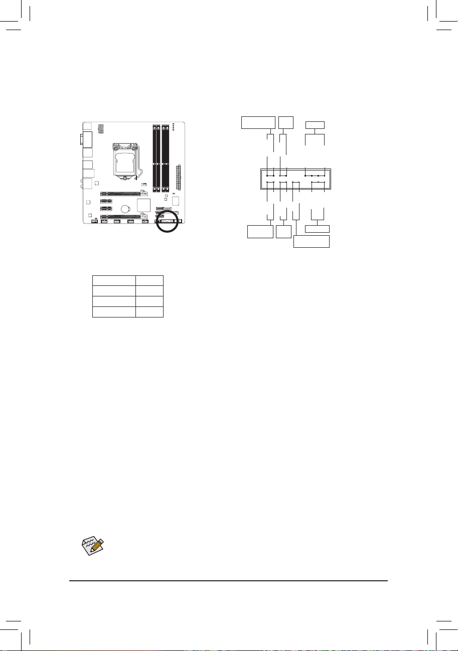
7) SATA2_2/3/4 (SATA 3Gb/s Connectors, Controlled by H67 Chipset)
The SATA connectors conform to SATA 3Gb/s standard and are compatible with SATA 1.5Gb/s stan-
dard. Each SATA connector supports a single SATA device.
The H67 Chips et supports RAI D 0,
RAID 1, RAID 5, and RAID 10. Refer to Chapter 5, "Conguring SATA Hard Drive(s)," for instructions on
conguring a RAID array.
Pin No. Denition
1 GND
2 TXP
3 TXN
4 GND
5 RXN
6 RXP
7 GND
•
A RAID 0 or RAID 1 conguration requires at least two hard drives. If more than two hard
drives are to be used, the total number of hard drives must be an even number.
•
A RAID 5 conguration requires at least three hard drives. (The total number of hard drives
does not have to be an even number.)
•
A RAID 10 conguration requires four hard drives.
Please connect the L-shaped end of the
SATA cable to your SATA hard drive.
DEBUG
PORT
G.QBOFM
SATA2_4
1
7
SATA2_2
DEBUG
PORT
G.QBOFM
7
DEBUG
PORT
G.QBOFM
1
SATA2_3
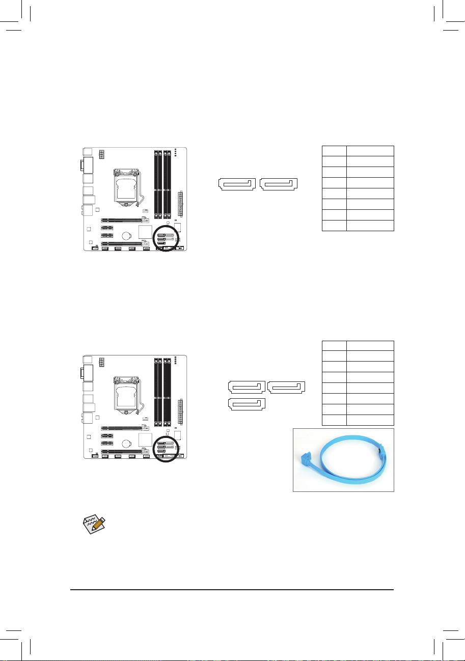
6) SATA3_0/1 (SATA 6Gb/s Connectors, Controlled by H67)
The SATA connectors conform to SATA 6Gb/s standard and are compatible with SATA 3Gb/s and SATA
1.5Gb/s standard. Each SATA connector supports a single SATA device. The SATA3_0 and SATA3_1
connectors support RAID 0 and RAID 1. RAID 5 and RAID 10 can be implemented on the two connectors with the SATA2_2/3/4 and eSATA connectors
(Note)
. Refer to Chapter 5, "Conguring SATA Hard
Drive(s)," for instructions on conguring a RAID array.
Pin No. Denition
1 GND
2 TXP
3 TXN
4 GND
5 RXN
6 RXP
7 GND
SATA3_0 SATA3_1
1
7
DEBUG
PORT
G.QBOFM
DEBUG
PORT
G.QBOFM
(Note) When a RAID set is built across the SATA 6Gb/s and SATA 3Gb/s channels, the system
performance of the RAID set may vary depending on the devices being connected.
- 26 -Hardware Installation
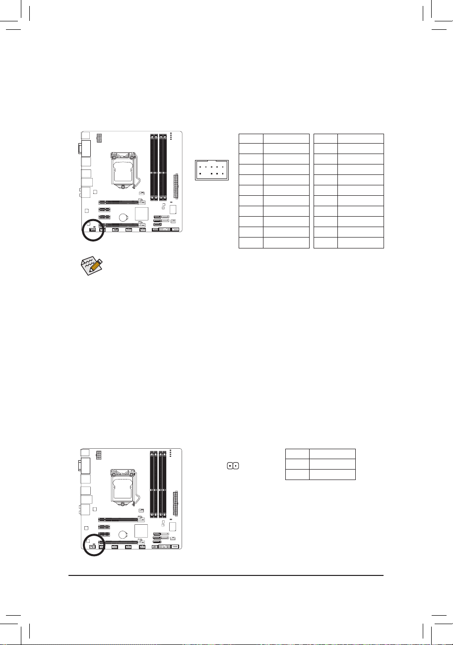
8) F_PANEL (Front Panel Header)
Connect the power switch, reset switch, speaker, chassis intrusion switch/sensor and system status
indicator on the chassis to this header according to the pin assignments below. Note the positive and
negative pins before connecting the cables.
•
PW (Power Switch, Red):
Connects to the power switch on the chassis front panel. You may congure the way to turn off your
system using the power switch (refer to Chapter 2, "BIOS Setup," "Power Management Setup," for
more information).
•
SPEAK (Speaker, Orange):
Connects to the speaker on the chassis front panel. The system reports system startup status by is-
suing a beep code. One single short beep will be heard if no problem is detected at system startup. If
a problem is detected, the BIOS may issue beeps in different patterns to indicate the problem. Refer
to Chapter 5, "Troubleshooting," for information about beep codes.
•
HD (Hard Drive Activity LED, Blue)
Connects to the hard drive activity LED on the chassis front panel. The LED is on when the hard drive
is reading or writing data.
•
RES (Reset Switch, Green):
Connects to the reset switch on the chassis front panel. Press the reset switch to restart the computer
if the computer freezes and fails to perform a normal restart.
•
CI (Chassis Intrusion Header, Gray):
Connects to the chassis intrusion switch/sensor on the chassis that can detect if the chassis cover
has been removed. This function requires a chassis with a chassis intrusion switch/sensor.
•
MSG/PWR (Message/Power/Sleep LED, Yellow/Purple):
Connects to the power status indicator on the chassis front panel. The LED
is on when the system is operating. The LED keeps blinking when the system is in S1 sleep state. The LED is off when the system is in S3/S4 sleep
state or powered off (S5).
System Status LED
S0 On
S1 Blinking
S3/S4/S5 Off
The front panel design may differ by chassis. A front panel module mainly consists of power
switch, reset switch, power LED, hard drive activity LED, speaker and etc. When connecting your
chassis front panel module to this header, make sure the wire assignments and the pin assignments are matched correctly.
Power LED
1
2
19
20
CI-
CI+
PWR-
PWR+
MSG-
PW-
SPEAK+
SPEAK-
MSG+
PW+
Message/Power/
Sleep LED
Speaker
Power
Switch
HD-
RES+
HD+
RES-
Hard Drive
Activity LED
Reset
Switch
Chassis Intrusion
Header
- 27 - Hardware Installation
9) F_AUDIO (Front Panel Audio Header)
The front panel audio header supports Intel High Denition audio (HD) and AC'97 audio. You may connect
your chassis front panel audio module to this header. Make sure the wire assignments of the module connector match the pin assignments of the motherboard header. Incorrect connection between the module
connector and the motherboard header will make the device unable to work or even damage it.
Pin No. Denition
1 MIC2_L
2 GND
3 MIC2_R
4 -ACZ_DET
5 LINE2_R
6 GND
7 FAUDIO_JD
8 No Pin
9 LINE2_L
10 GND
Pin No. Denition
1 MIC
2 GND
3 MIC Power
4 NC
5 Line Out (R)
6 NC
7 NC
8 No Pin
9 Line Out (L)
10 NC
For HD Front Panel Audio: For AC'97 Front Panel Audio:
•
The front panel audio header supports HD audio by default. If your chassis provides an AC'97
front panel audio module, refer to the instructions on how to activate AC'97 functionality via
the audio software in Chapter 5, "Conguring 2/4/5.1/7.1-Channel Audio."
•
Audio signals will be present on both of the front and back panel audio connections simultane-
ously. If you want to mute the back panel audio (only supported when using an HD front panel
audio module), refer to Chapter 5, "Conguring 2/4/5.1/7.1-Channel Audio."
•
Some chassis provide a front panel audio module that has separated connectors on each wire
instead of a single plug. For information about connecting the front panel audio module that
has different wire assignments, please contact the chassis manufacturer.
1
2
9
10
Pin No. Denition
1 SPDIFO
2 GND
10) SPDIF_O (S/PDIF Out Header)
This header supports digital S/PDIF Out and connects a S/PDIF digital audio cable (provided by expan-
sion cards) for digital audio output from your motherboard to certain expansion cards like graphics cards
and sound cards. For example, some graphics cards may require you to use a S/PDIF digital audio cable
for digital audio output from your motherboard to your graphics card if you wish to connect an HDMI
display to the graphics card and have digital audio output from the HDMI display at the same time. For
information about connecting the S/PDIF digital audio cable, carefully read the manual for your expansion card.
1
- 28 -Hardware Installation
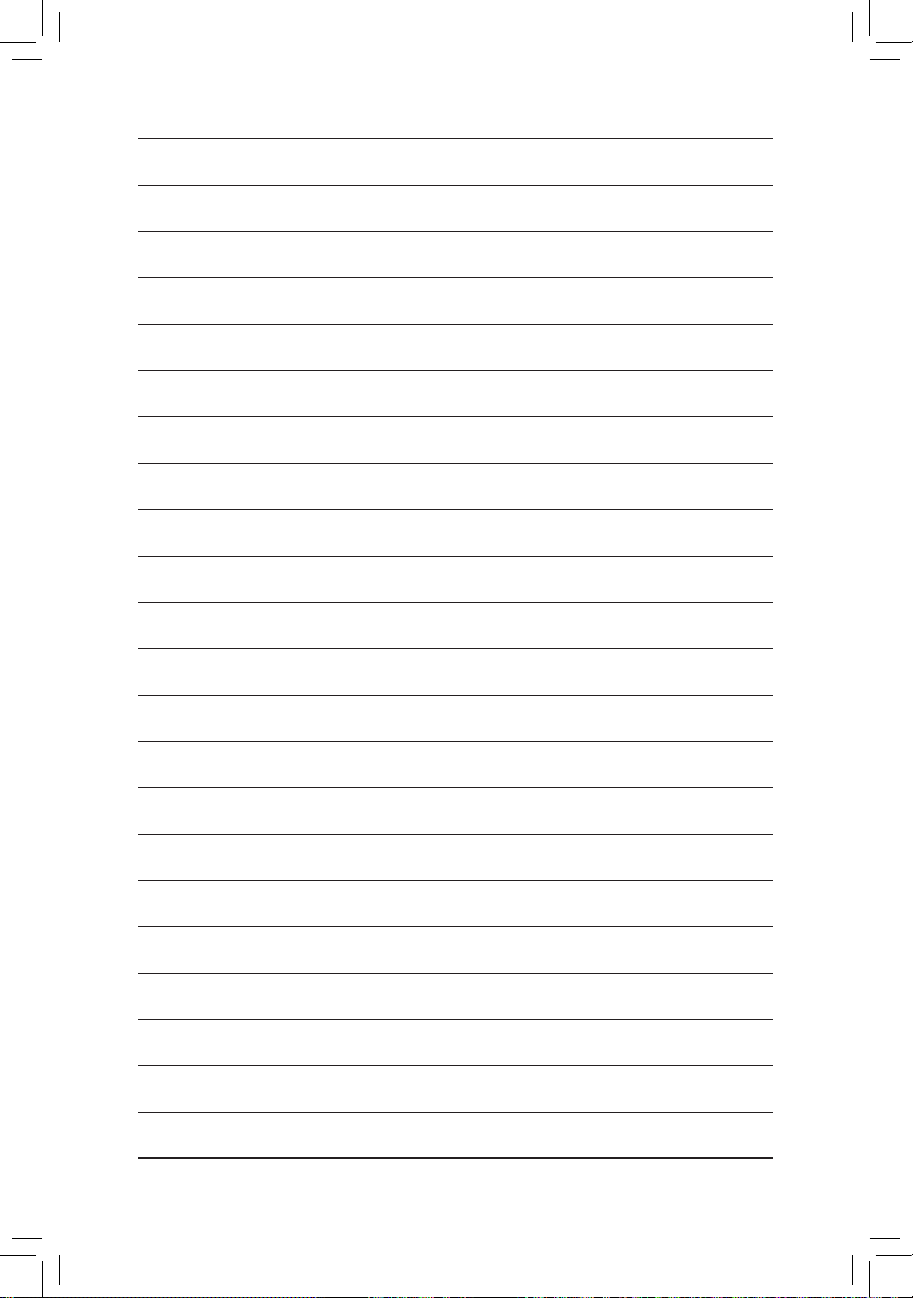
11) F_USB1/2/3/4/5 (USB Headers)
The headers conform to USB 2.0/1.1 specication. Each USB header can provide two USB ports via an
optional USB bracket. For purchasing the optional USB bracket, please contact the local dealer.
G.QBOFM
10
9
2
1
Pin No. Denition
1 Power (5V)
2 Power (5V)
3 USB DX-
4 USB DY-
5 USB DX+
6 USB DY+
7 GND
8 GND
9 No Pin
10 NC
•
Do not plug the IEEE 1394 bracket (2x5-pin) cable into the USB header.
•
Prior to installing the USB bracket, be sure to turn off your computer and unplug the power
cord from the power outlet to prevent damage to the USB bracket.
When the system is in S4/S5 mode, only the USB ports routed to the F_USB1 header can support the ON/OFF Charge function.
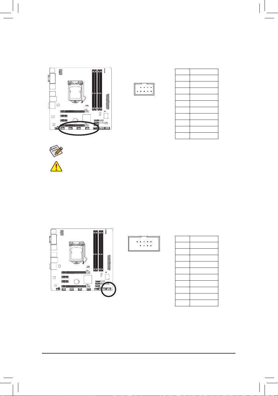
12) COM (Serial Port Header)
The COM header can provide one serial port via an optional COM port cable. For purchasing the op-
tional COM port cable, please contact the local dealer.
10
9
2
1
Pin No. Denition
1 NDCD-
2 NSIN
3 NSOUT
4 NDTR-
5 GND
6 NDSR-
7 NRTS-
8 NCTS-
9 NRI-
10 No Pin
- 29 - Hardware Installation
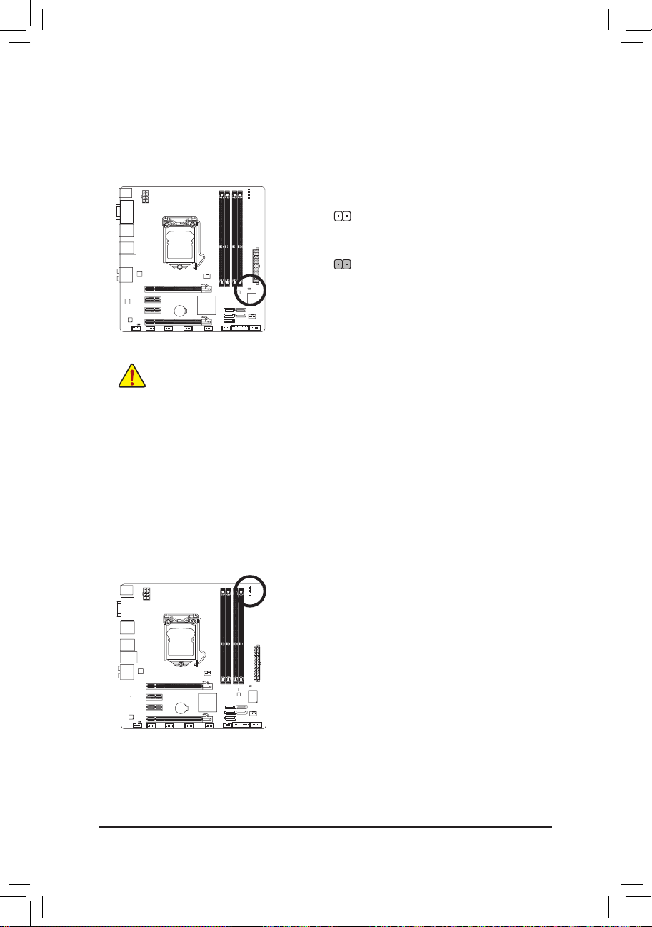
13) CLR_CMOS (Clearing CMOS Jumper)
Use this jumper to clear the CMOS values (e.g. date information and BIOS congurations) and reset
the CMOS values to factory defaults. To clear the CMOS values, place a jumper cap on the two pins to
temporarily short the two pins or use a metal object like a screwdriver to touch the two pins for a few
seconds.
•
Always turn off your computer and unplug the power cord from the power outlet before clear-
ing the CMOS values.
•
After clearing the CMOS values and before turning on your computer, be sure to remove the
jumper cap from the jumper. Failure to do so may cause damage to the motherboard.
•
After system restart, go to BIOS Setup to load factory defaults (select Load Optimized De-
faults) or manually congure the BIOS settings (refer to Chapter 2, "BIOS Setup," for BIOS
congurations).
Open: Normal
Short: Clear CMOS Values
14) PHASE LED
The number of lighted LEDs indicates the CPU loading. The higher the CPU loading, the more the
number of lighted LEDs. To enable the Phase LED display function, please rst enable Dynamic Energy
Saver™ 2. Refer to Chapter 4, "Dynamic Energy Saver™ 2," for more details.
- 30 -Hardware Installation
 Loading...