

Page 1

GA-EX58-EXTREME
LGA1366 socket motherboard for Intel® Core
TM
i7 processor family
User's Manual
Rev. 1003
12ME-EX58EX-1003R
Page 2
Oct. 31, 2008
Motherboard
GA-EX58-EXTREME
Motherboard
GA-EX58-EXTREME
Oct. 31, 2008
Page 3
Copyright
© 2009 GIGA-BYTE TECHNOLOGY CO., LTD. All rights reserved.
The trademarks mentioned in this manual are legally registered to their respective owners.
Disclaimer
Information in this manual is protected by copyright laws and is the property of GIGABYTE.
Changes to the specifications and features in this manual may be made by GIGABYTE without prior
notice. No part of this manual may be reproduced, copied, translated, transmitted, or published in any
form or by any means without GIGABYTE's prior written permission.
Documentation Classifications
In order to assist in the use of this product, GIGABYTE provides the following types of documentations:
For quick set-up of the product, read the Quick Installation Guide included with the product.
For detailed product information, carefully read the User's Manual.
For instructions on how to use GIGABYTE's unique features, read or download the
information on/from the Support\Motherboard\T echnology Guide page on our website.
For product-related information, check on our website at:
http://www.gigabyte.com.tw
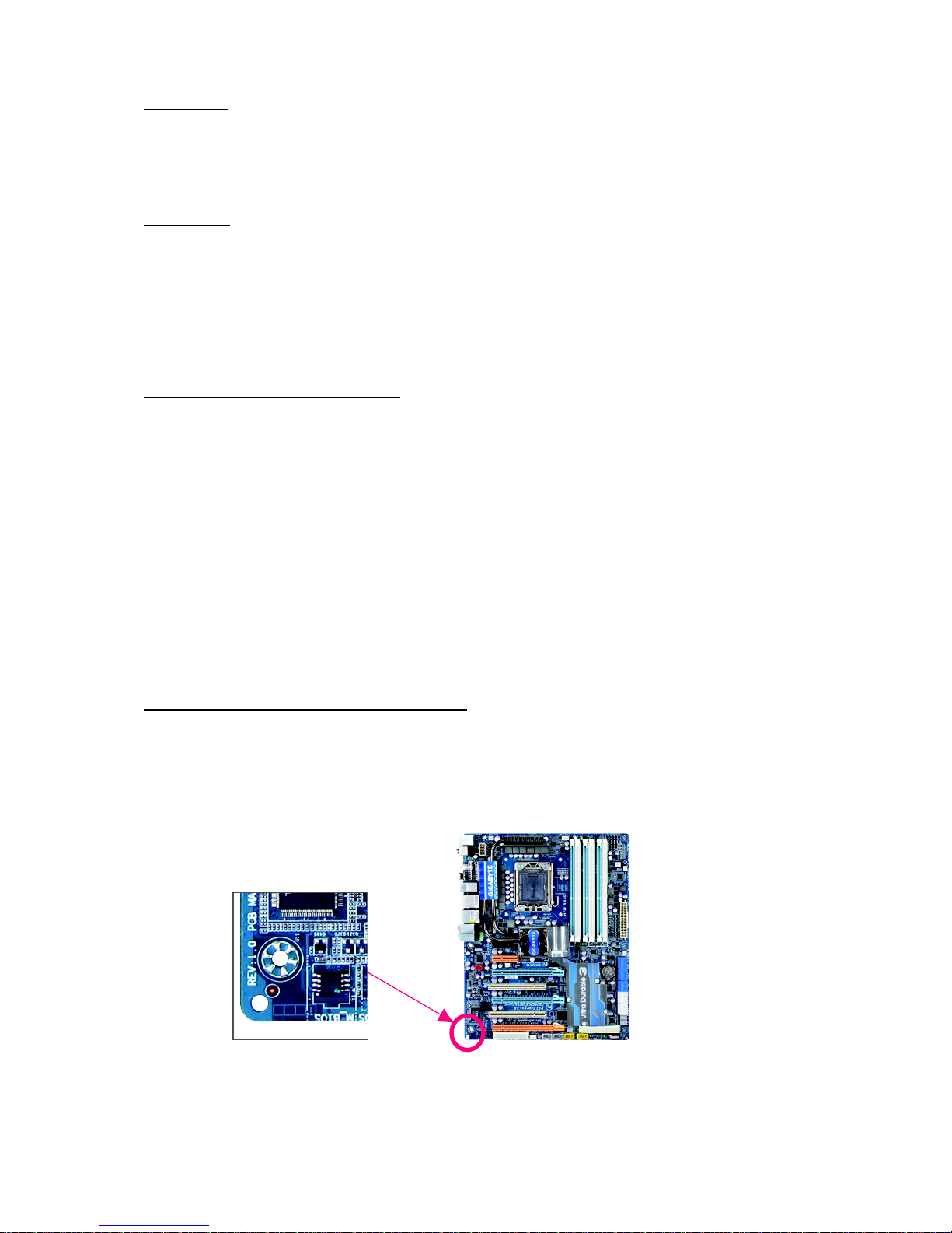
Identifying Your Motherboard Revision
The revision number on your motherboard looks like this: "REV: X.X." For example, "REV: 1.0"
means the revision of the motherboard is 1.0. Check your motherboard revision before updating
motherboard BIOS, drivers, or when looking for technical information.
Example:
Page 4

- 4 -
Table of Contents
Box Contents ................................................................................................................. 6
Optional Items................................................................................................................. 6
GA-EX58-EXTREME Motherboard Layout .................................................................... 7
Block Diagram................................................................................................................ 8
Chapter 1 Hardware Installation .................................................................................... 9
1- 1 Installation Precautions .....................................................................................9
1- 2 Product Specifications .................................................................................... 10
1-3 Installing the CPU and CPU Cooler.............................................................. 13
1-3-1 Installing the CPU ................................................................................................ 13
1-3-2 Installing the CPU Cooler ................................................................................... 15
1- 4 Installing the Hybrid Silent-Pipe Module......................................................... 16
1- 5 Installing the Memory..................................................................................... 17
1-5-1 Dual/3 Channel Memory Configuration ............................................................ 17
1-5-2 Installing a Memory............................................................................................. 18
1-6 Installing an Expansion Card ......................................................................... 19
1- 7 Setup of NVIDIA SLI (Scalable Link Interface)/ATI CrossFireX Configuration 2 0
1- 8 Installing the SA T A Bracket............................................................................. 23
1-9 Back Panel Connectors ................................................................................. 24
1-10 Onboard LEDs and Switches......................................................................... 2 6
1-11 Internal Connectors ........................................................................................ 28
Chapter 2 BIOS Setup................................................................................................. 41
2- 1 Startup Screen................................................................................................ 42
2- 2 The Main Menu .............................................................................................. 43
2-3 MB Intelligent Tweaker(M.I.T.)....................................................................... 45
2-4 Standard CMOS Features ............................................................................. 55
2-5 Advanced BIOS Features.............................................................................. 57
2- 6 Integrated Peripherals ..................................................................................... 59
2- 7 Power Management Setup............................................................................. 64
2-8 PC Health Status ........................................................................................... 6 6
2- 9 Load Fail-Safe Defaults ................................................................................... 68
2-10 Load Optimized Defaults................................................................................. 68
2-11 Set Supervisor/User Password..................................................................... 69
2-12 Save & Exit Setup......................................................................................... 70
2-13 Exit Without Saving ....................................................................................... 70
Page 5

- 5 -
Chapter 3 Drivers Installation ......................................................................................71
3- 1 Installing Chipset Drivers ............................................................................... 71
3- 2 Application Software....................................................................................... 72
3-3 Technical Manuals.......................................................................................... 72
3-4 Contact........................................................................................................... 73
3-5 System........................................................................................................... 73
3- 6 Download Center............................................................................................ 74
Chapter 4 Unique Features......................................................................................... 75
4- 1 Xpress Recovery2 ......................................................................................... 7 5
4-2 BIOS Update Utilities..................................................................................... 78
4-2-1 Updating the BIOS with the Q-Flash Utility...................................................... 78
4-2-2 Updating the BIOS with the @BIOS Utility ....................................................... 81
4- 3 EasyTune 6.................................................................................................... 8 2
4-4 Dynamic Energy Saver Advanced ................................................................ 83
4-5 Q-Share ......................................................................................................... 85
4- 6 Time Repair.................................................................................................... 86
4-7 T eaming.......................................................................................................... 87
Chapter 5 Appendix .................................................................................................... 89
5-1 Configuring SATA Hard Drive(s) .................................................................... 8 9
5-1-1 Configuring Intel ICH10R SATA Controllers ...................................................... 89
5-1-2 Configuring GIGABYTE SATA2/JMB322 SATA Controller.............................. 95
5-1-3 Making a SATA RAID/AHCI Driver Diskette ..................................................... 97
5-1-4 Installing the SATA RAID/AHCI Driver and Operating System ...................... 99
5-1-5 Smart Backup Utility .......................................................................................... 104
5- 2 Configuring Audio Input and Output............................................................... 105
5-2-1 Configuring 2/4/5.1/7.1-Channel Audio .......................................................... 105
5-2-2 Configuring S/PDIF In/Out ................................................................................ 107
5-2-3 Enabling the Dolby Home Theater Function .................................................. 109
5-2-4 Configuring Microphone Recording ................................................................. 110
5-2-5 Using the Sound Recorder............................................................................... 112
5-3 Troubleshooting ..............................................................................................113
5-3-1 Frequently Asked Questions ........................................................................... 113
5-3-2 Troubleshooting Procedure .............................................................................. 114
5-4 POST Error Code .........................................................................................116
5- 5 Regulatory Statements ................................................................................. 120
Page 6
- 6 -
Box Contents
GA-EX58-EXTREME motherboard
Motherboard driver disk
User's Manual
Quick Installation Guide
One IDE cable and one floppy disk drive cable
Four SATA 3Gb/s cables
One SA T A bracket
I/O shield
One Hybrid Silent-Pipe module kit
2-Way SLI bridge connector
3-Way SLI bridge connector
Optional Items
2-port USB 2.0 bracket (Part No. 12CR1-1UB030-5*R)
2-port IEEE 1394a bracket (Part No. 12CF1-1IE008-0*R)
2-port SATA power cable (Part No. 12CF1-2SERPW-0*R)
S/PDIF in cable (Part No. 12CR1-1SPDIN-0*R)
• The box contents above are for reference only and the actual items shall depend on product package you obtain.
The box contents are subject to change without notice.
• The motherboard image is for reference only.
Page 7
- 7 -
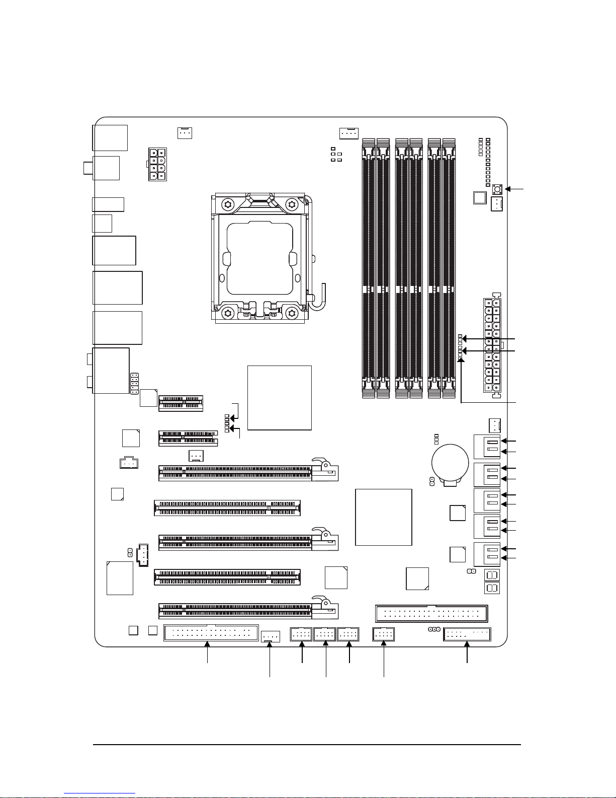
GA-EX58-EXTREME Motherboard Layout
F_USB1F2_1394
KB_MS
CPU_FAN
LGA1366
ATX
GA-EX58-EXTREME
F_AUDIO
PWR_FAN
ATX_12V_2X
Intel® X58
USB_LAN2
AUDIO
R_SPDIF
PCIEX1_1
(Note 1)
R_USB
CD_IN
PWR_LED
IDE
SPDIF_I
PCIEX4_1
PCIEX16_1
CODEC
TSB43AB23
PCIEX8_1
PCIEX16_2
IT8720
Intel® ICH10R
M_BIOS
B_BIOS
DDR3_4
DDR3_3
SPDIF_O
PHASE LED
USB_LAN1
RTL8111D
PCI2
F_PANELF_USB2
F1_1394
Debug
LED
(Note 2)
CMOS_SW
RST_SW
PW_SW
CLR_CMOS
FREQ. LED
CPU Voltage L1/2/3
CPU TEMP L1/2
SB Voltage L1/2/3
NB Voltage L1/2/3
NB TEMP L1/2
V1394-1
DDR3_2
DDR3_1
DDR3_6
DDR3_5
SYS_FAN2
FDD
BATTERY
RTL8111D
SATA2_0
SATA2_1
SATA2_2
SATA2_3
SATA2_4
SATA2_5
SYS_FAN1
CI
NB PHASE LED
SYS_FAN3
GSATA2_1
GSATA2_0
GSATA2_3
GSATA2_2
GIGABYTE
SATA2
PCI1
NB_FAN
JMB322
JMB322
DDR PHASE LED
DDR Voltage LED
(Note 1) Due to a hardware limitation, the PCIEX1_1 slot can only accommodate a shorter PCI Express x1
expansion card. For a longer expansion card, use other expansion slots.
(Note 2) For error code information, please refer to Chapter 5.
Page 8
- 8 -
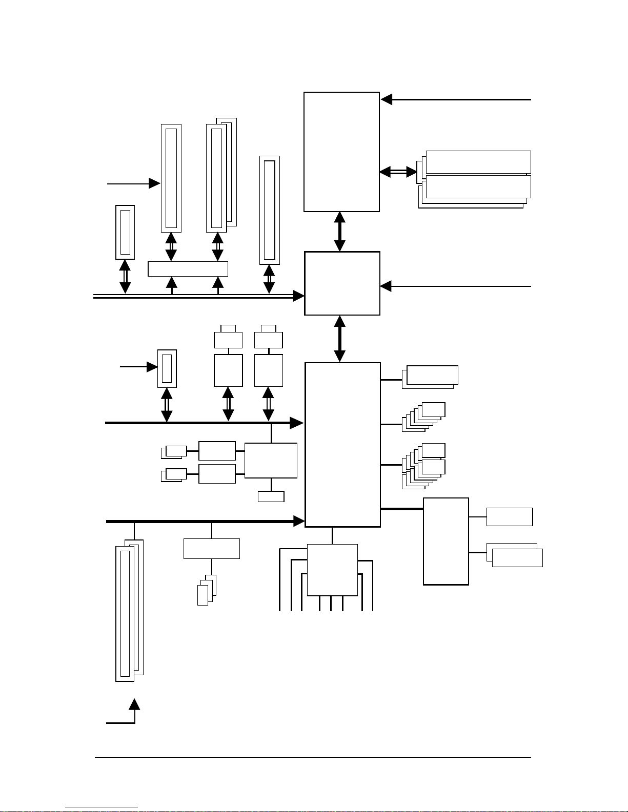
Block Diagram
LGA1366
Processor
QPI
Interface
Intel
®
X58
IOH CLK (13 3 MHz)
DDR3 2100/1333/1066/800 MHz
Dual BIOS
2 PCI
PCI Bus
6 SATA 3Gb/s
PCI CLK
(33 MHz)
12 USB Ports
CPU CLK+/- (133 MHz)
Center/Subwoofer Speaker Out
Line-Out
MIC
Line-In
SPDIF In
SPDIF Out
Side Speaker Out
Surround Speaker Out
CODEC
Intel
®
ICH10R
Floppy
PS/2 KB/Mouse
3 IEEE 1394a
TSB43AB23
LPC Bus
IT8720
PCIe CLK
(100 MHz)
2 SATA 3Gb/s
JMB322
1 PCI Express x1
PCI Express Bus
2 SATA 3Gb/s
ATA-133/100/66/33 IDE Channel
GIGABYTE
SATA2
JMB322
x1
RTL
81 11D
LAN1
RJ45
x1
RTL
81 11D
LAN2
RJ45
x1
x4
1 PCI Express x4
PCI Express Bus
2 PCI Express x8
1 PCI Express x16
PCIe CLK
(100 MHz) or
Switch
x8x16
x1
x16
1 PCI Express x16
Dual/3 Channel Memory
Page 9

Hardware Installation- 9 -
1- 1 Installation Precautions
The motherboard contains numerous delicate electronic circuits and components which can become
damaged as a result of electrostatic discharge (ESD). Prior to installation, carefully read the user's
manual and follow these procedures:
• Prior to installation, do not remove or break motherboard S/N (Serial Number) sticker or
warranty sticker provided by your dealer. These stickers are required for warranty validation.
• Always remove the AC power by unplugging the power cord from the power outlet before
installing or removing the motherboard or other hardware components.
• When connecting hardware components to the internal connectors on the motherboard,
make sure they are connected tightly and securely.
• When handling the motherboard, avoid touching any metal leads or connectors.
• It is best to wear an electrostatic discharge (ESD) wrist strap when handling electronic
components such as a motherboard, CPU or memory. If you do not have an ESD wrist strap,
keep your hands dry and first touch a metal object to eliminate static electricity.
• Prior to installing the motherboard, please have it on top of an antistatic pad or within an
electrostatic shielding container.
• Before unplugging the power supply cable from the motherboard, make sure the power supply
has been turned off.
• Before turning on the power, make sure the power supply voltage has been set according to
the local voltage standard.
• Before using the product, please verify that all cables and power connectors of your hardware
components are connected.
• T o prevent damage to the motherboard, do not allow screws to come in contact with the
motherboard circuit or its components.
• Make sure there are no leftover screws or metal components placed on the motherboard or
within the computer casing.
• Do not place the computer system on an uneven surface
.
• Do not place the computer system in a high-temperature environment.
• Turning on the computer power during the installation process can lead to damage to system
components as well as physical harm to the user.
• If you are uncertain about any installation steps or have a problem related to the use of the
product, please consult a certified computer technician.
Chapter 1 Hardware Installation
Page 10

GA-EX58-EXTREME Motherboard - 10 -
1- 2 Product Specifications
CPU Support for an Intel® Core
TM
i7 series processor in the LGA1366 package
(Go to GIGABYTE's website for the latest CPU support list.)
L3 cache varies with CPU
QPI 4.8GT/s / 6.4GT/s
Chipset North Bridge: Intel® X58 Express Chipset
South Bridge: Intel® ICH10R
Memory 6 x 1.5V DDR3 DIMM sockets supporting up to 24 GB of system memory
(Note 1)
Dual/3 channel memory architecture
Support for DDR3 2100/1333/1066/800 MHz memory modules
(Go to GIGABYTE's website for the latest memory support list.)
Audio Realtek ALC889A codec
High Definition Audio
2/4/5.1/7.1-channel
Support for Dolby® Home Theater
Support for S/PDIF In/Out
Support for CD In
LAN 2 x Realtek 8111D chips (10/100/1000 Mbit)
Support for Teaming
Expansion Slots 2 x PCI Express x16 slots, running at x16 (PCIEX16_1/PCIEX16_2)
(Note 2)
1 x PCI Express x8 slot, running at x8 (PCIEX8_1)
(Note 3)
(The PCIEX16_1, PCIE16_2 and PCIEX8_1 slots support 2-Way/3-Way
NVIDIA SLI/ATI CrossFireXTM technology and conform to PCI Express 2.0
standard.)
1 x PCI Express x4 slot
1 x PCI Express x1 slot
2 x PCI slots
Storage Interface South Bridge:
- 6 x SATA 3Gb/s connectors (SATA2_0, SATA2_1, SATA2_2, SATA2_3,
SATA2_4, SATA2_5) supporting up to 6 SATA 3Gb/s devices
- Support for SATA RAID 0, RAID 1, RAID 5, and RAID 10
GIGABYTE SATA2 chip:
- 1 x IDE connector supporting ATA-133/100/66/33 and up to 2 IDE devices
2 x JMB322 chips (Smart Backup):
- 4 x SATA 3Gb/s connectors (GSATA2_0, GSATA2_1, GSATA2_2,
GSATA2_3 ) supporting up to 4 SATA 3Gb/s devices
(Note 4)
- Support for SATA RAID 0, RAID 1 and JBOD
iTE IT8720 chip:
- 1 x floppy disk drive connector supporting up to 1 floppy disk drive
IEEE 1394 T.I. TSB43AB23 chip
Up to 3 IEEE 1394a ports (1 on the back panel, 2 via the IEEE 1394a
brackets connected to the internal IEEE 1394a headers)
Page 11

Hardware Installation- 11 -
USB Integrated in the South Bridge
Up to 12 USB 2.0/1.1 ports (8 on the back panel, 4 via the USB brackets
connected to the internal USB headers)
Internal Connectors 1 x 24-pin ATX main power connector
1 x 8-pin ATX 12V power connector
1 x floppy disk drive connector
1 x IDE connector
10 x SATA 3Gb/s connectors
1 x CPU fan header
3 x system fan headers
1 x power fan header
1 x North Bridge fan header
1 x front panel header
1 x front panel audio header
1 x CD In connector
1 x S/PDIF In header
1 x S/PDIF Out header
2 x USB 2.0/1.1 headers
2 x IEEE 1394a headers
1 x power LED header
1 x chassis intrusion header
1 x power switch
1 x reset switch
Back Panel 1 x PS/2 keyboard port
Connectors 1 x PS/2 mouse port
1 x coaxial S/PDIF Out connector
1 x optical S/PDIF Out connector
1 x IEEE 1394a port
1 x clearing CMOS switch
8 x USB 2.0/1.1 ports
2 x RJ-45 ports
6 x audio jacks (Center/Subwoofer Speaker Out/Rear Speaker Out/Side
Speaker Out/Line In/Line Out/Microphone)
I/O Controller iTE IT8720 chip
Hardware Monitor System voltage detection
CPU/System/North Bridge temperature detection
CPU/System/Power fan speed detection
CPU overheating warning
CPU/System/Power fan fail warning
CPU/System fan speed control
(Note 5)
Page 12

GA-EX58-EXTREME Motherboard - 12 -
BIOS 2 x 8 Mbit flash
Use of licensed AWARD BIOS
Support for DualBIOS
TM
PnP 1.0a, DMI 2.0, SM BIOS 2.4, ACPI 1.0b
Unique Features Support for @BIOS
Support for Q-Flash
Support for Virtual Dual BIOS
Support for Download Center
Support for Xpress Install
Support for Xpress Recovery2
Support for EasyTune
(Note 6)
Support for Dynamic Energy Saver Advanced
Support for Time Repair
Support for Q-Share
Bundled Software Norton Internet Security (OEM version)
Operating System Support for Microsoft® Windows® Vista/XP
Form Factor ATX Form Factor; 30.5cm x 24.4cm
(Note 1) Due to Windows Vista/XP 32-bit operating system limitation, when more than 4 GB of physical
memory is installed, the actual memory size displayed will be less than 4 GB.
(Note 2) For optimum performance, if only one PCI Express graphics card is to be installed, be sure to
install it in the PCIEX16_1 slot; if you are installing two PCI Express graphics cards, it is
recommended that you install them in the PCIEX16_1 and PCIEX16_2 slots.
(Note 3) The PCIEX8_1 slot shares bandwidth with the PCIEX16_2 slot. When PCIEX8_1 is populated
with a PCI Express graphics card, the PCIEX16_2 slot will operate at up to x8 mode.
(Note 4) A JMB322 chip supports two SATA 3Gb/s connectors, so the four SATA 3Gb/s connectors are
divided into to two pairs: GSATA2_0 and GSATA2_1 as a pair and GSATA2_2 and GSATA2_3 as
a pair. (Refer to Chapter 2, "Integrated Peripherals" and Chapter 5, "Configuring SATA Hard
Drive(s)," for how to enable the Smart Backup function.)
(Note 5) Whether the CPU/system fan speed control function is supported will depend on the CPU/
system cooler you install.
(Note 6) Available functions in EasyTune may differ by motherboard model.
Page 13
Hardware Installation- 13 -
1-3 Installing the CPU and CPU Cooler
Read the following guidelines before you begin to install the CPU:
• Make sure that the motherboard supports the CPU.
(Go to GIGABYTE's website for the latest CPU support list.)
• Always turn off the computer and unplug the power cord from the power outlet before
installing the CPU to prevent hardware damage.
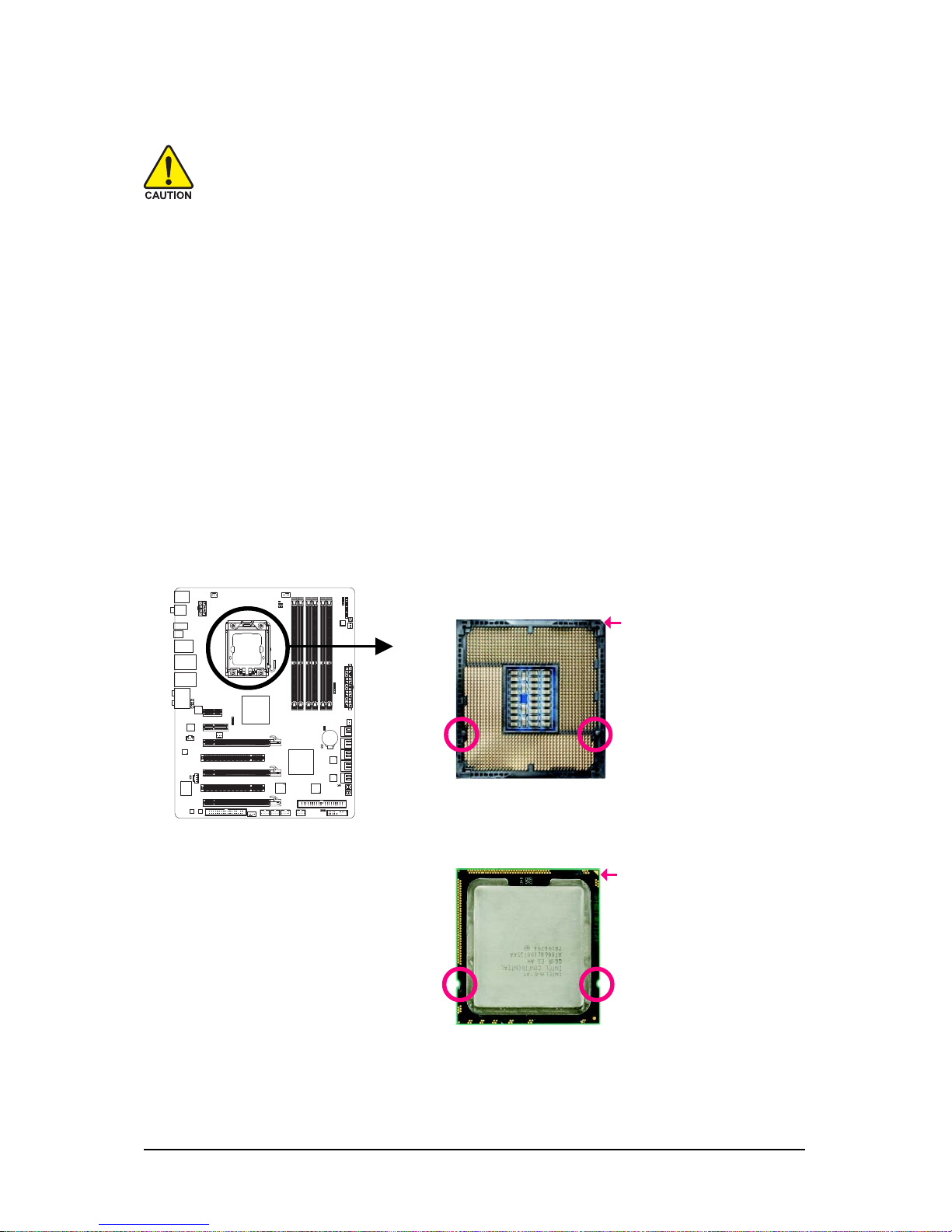
• Locate the pin one of the CPU. The CPU cannot be inserted if oriented incorrectly. (Or you
may locate the notches on both sides of the CPU and alignment keys on the CPU socket.)
• Apply an even and thin layer of thermal grease on the surface of the CPU.
• Do not turn on the computer if the CPU cooler is not installed, otherwise overheating and
damage of the CPU may occur.
• Set the CPU host frequency in accordance with the CPU specifications. It is not recommended that the system bus frequency be set beyond hardware specifications since it
does not meet the standard requirements for the peripherals. If you wish to set the frequency
beyond the standard specifications, please do so according to your hardware specifications including the CPU, graphics card, memory, hard drive, etc.
1-3-1 Installing the CPU
A. Locate the alignment keys on the motherboard CPU socket and the notches on the CPU.
NotchNotch
Alignment Key Alignment Key
LGA1366 CPU
LGA1366 CPUSocket
Pin One Corner of the CPU Socket
Triangle Pin One Marking on the CPU
Page 14
GA-EX58-EXTREME Motherboard - 14 -
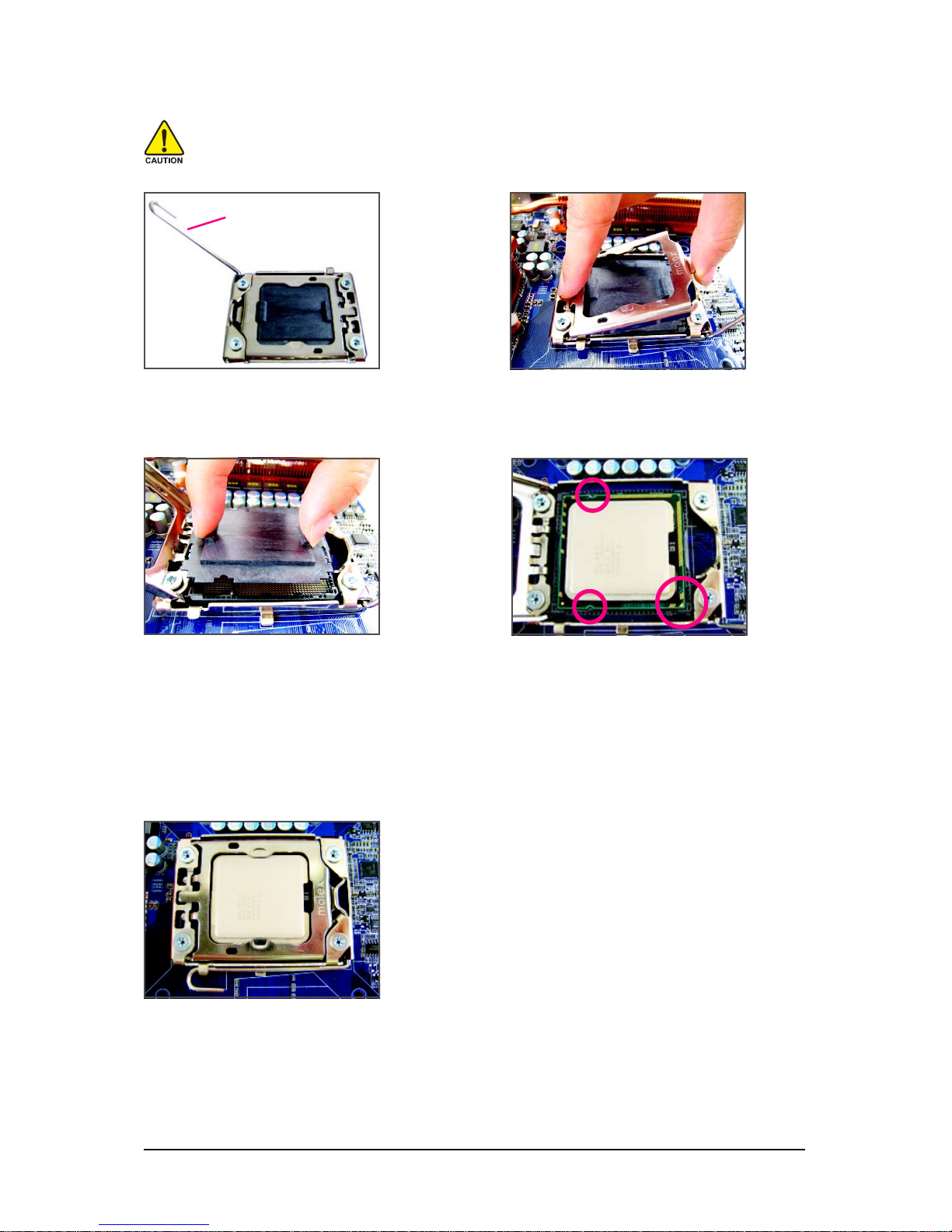
B. Follow the steps below to correctly install the CPU into the motherboard CPU socket.
Before installing the CPU, make sure to turn off the computer and unplug the power
cord from the power outlet to prevent damage to the CPU.
Step 2:
Lift the metal load plate from the CPU socket.
Step 1:
Completely raise the CPU socket lever.
Step 4:
Hold the CPU with your thumb and index finger.
Align the CPU pin one marking (triangle) with
the pin one corner of the CPU socket (or you
may align the CPU notches with the socket
alignment keys) and gently insert the CPU
into position.
Step 3:
Use your thumb and index finger to hold the
protective socket cover as indicated and lift it
up vertically. (DO NOT touch socket contacts.
To protect the CPU socket, always replace the
protective socket cover when the CPU is not
installed.)
Step 5:
Once the CPU is properly inserted, replace
the load plate and push the CPU socket lever
back into its locked position.
CPU Socket Lever
Page 15
Hardware Installation- 15 -
1-3-2 Installing the CPU Cooler
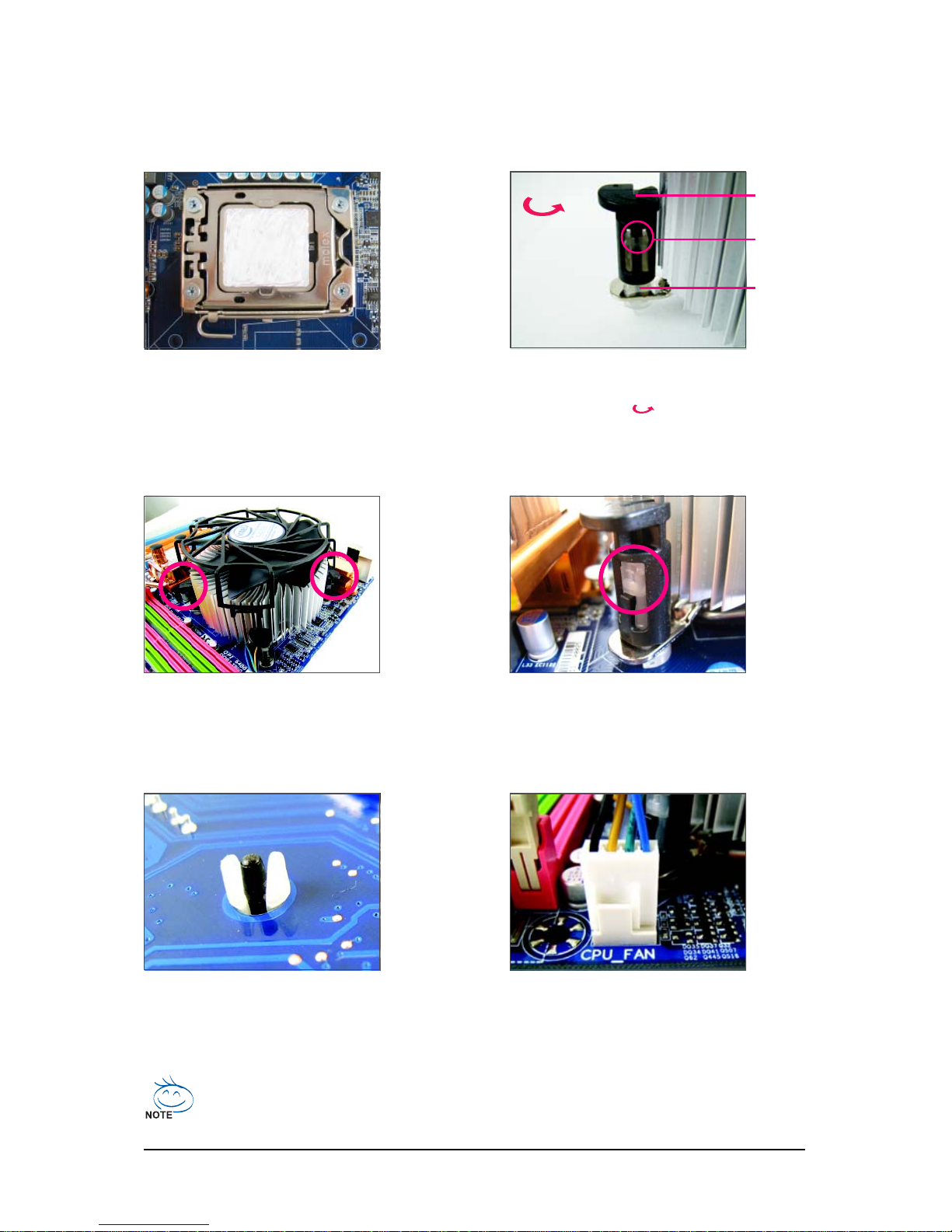
Follow the steps below to correctly install the CPU cooler on the motherboard. (The following procedure
uses Intel® boxed cooler as the example cooler.)
Step 2:
Before installing the cooler, note the direction
of the arrow sign on the male push pin.
(Turning the push pin along the direction of
arrow is to remove the cooler, on the contrary,
is to install.)
Step 1:
Apply an even and thin layer of thermal grease
on the surface of the installed CPU.
Step 3:
Place the cooler atop the CPU, aligning the
four push pins through the pin holes on the
motherboard. Push down on the push pins
diagonally.
Step 4:
You should hear a "click" when pushing down each
push pin. Check that the Male and Female push pins
are joined closely. (Refer to your CPU cooler installation manual for instructions on installing the cooler.)
Step 5:
After the installation, check the back of the
motherboard. If the push pin is inserted as the
picture above shows, the installation is complete.
Step 6:
Finally, attach the power connector of the CPU
cooler to the CPU fan header (CPU_FAN) on
the motherboard.
Use extreme care when removing the CPU cooler because the thermal grease/tape between
the CPU cooler and CPU may adhere to the CPU. Inadequately removing the CPU cooler may
damage the CPU.
Male
Push Pin
Female
Push Pin
The Top of
Female
Push Pin
Direction of
the Arrow
Sign on the
Male Push
Pin
Page 16
GA-EX58-EXTREME Motherboard - 16 -
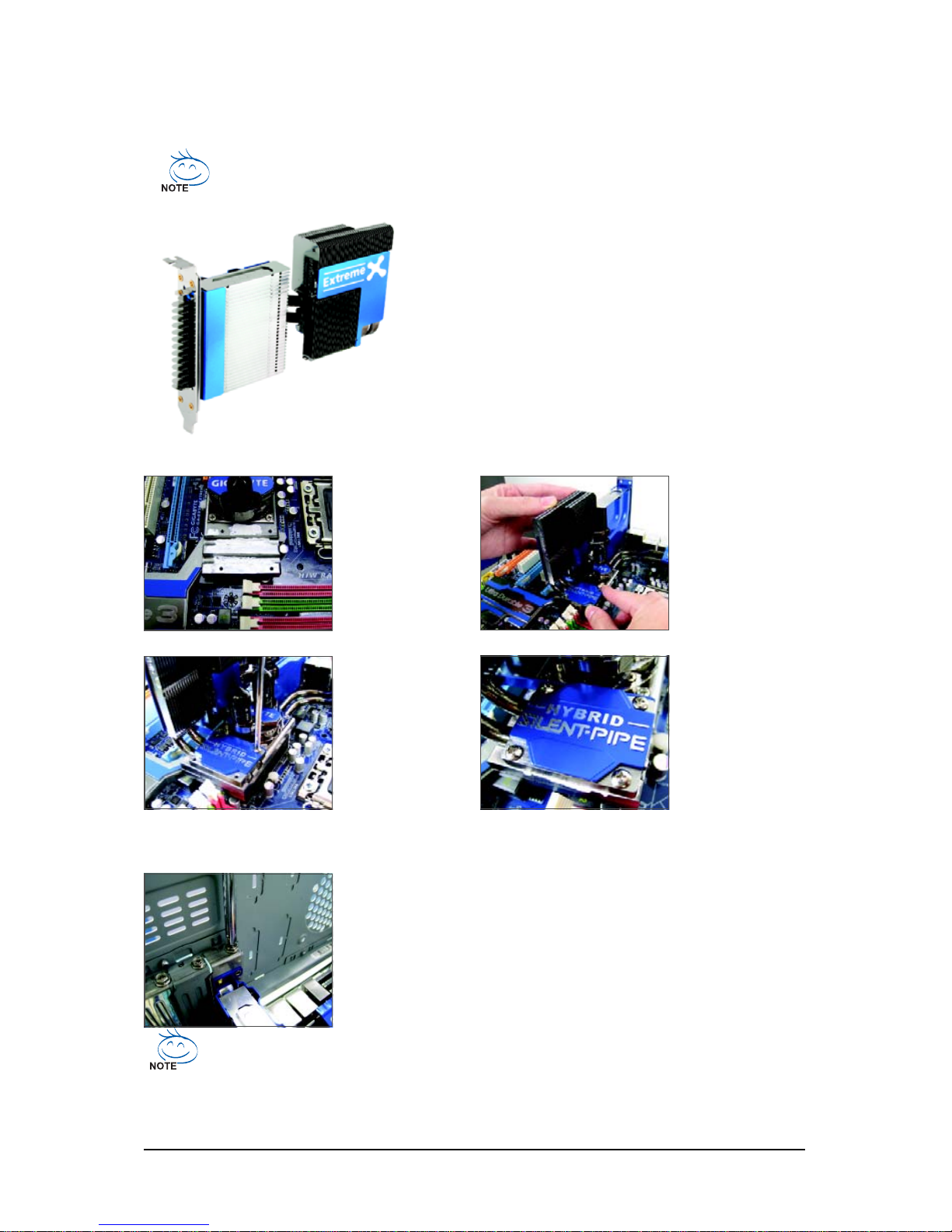
1-4 Installing the Hybrid Silent-Pipe Module
Read the following guideline before you begin to install the Hybrid Silent-Pipe module:
If you want to connect the front audio module from your chassis to the F_AUDIO connector
on the motherboard, be sure to connect it before installing the Hybrid Silent-Pipe module to
avoid interference.
Tools needed:
1. A Philip's screwdriver
2. Thermal grease
3. Screws included with the motherboard
(Note) The components received may vary in appearance from the products illustrated.
Hybrid Silent-Pipe
Step 1:
Apply an even thin
layer of thermal
grease on the surface of the North
Bridge heatsink base
and it grooves.
Follow the steps below to install the Hybrid Silent-Pipe module:
Step 2:
Position the heatpipe
underneath the
heatsink of the Hybrid
Silent-Pipe module into
the tunnel of the North
Bridge heasink base.
Step 3:
Secure the Hybrid
Silent-Pipe heatsink
to the heatsink base
by the included
screws.(Use one
hand to hold the top
of the fins to avoid
shaking.)
Step 4:
The picture on the left
shows that four
screws are fastened
to the heatsink and
heatsink base.
Step 5:
Secure the Hybrid Silent-Pipe bracket to the chassis back panel with a
screw to complete the installation.
For the waterblocks on the North Bridge heatsink, we recommend tubes with inner diameter
of 7.5mm and outer diameter of 10mm. After connecting the tubes, make sure that the tubes are
attached to the waterblocks securely and tightly and there is no leak.
Page 17
Hardware Installation- 17 -
1-5 Installing the Memory
Read the following guidelines before you begin to install the memory:
• Make sure that the motherboard supports the memory. It is recommended that memory of
the same capacity, brand, speed, and chips be used.
(Go to GIGABYTE's website for the latest memory support list.)
• Always turn off the computer and unplug the power cord from the power outlet before
installing the memory to prevent hardware damage.
• Memory modules have a foolproof design. A memory module can be installed in only one
direction. If you are unable to insert the memory, switch the direction.
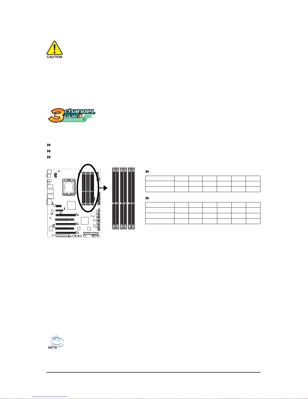
1-5-1 Dual/3 Channel Memory Configuration
This motherboard provides six DDR3 memory sockets and supports Dual/3
Channel Technology. After the memory is installed, the BIOS will automatically
detect the specifications and capacity of the memory. Dual or 3 Channel
memory mode may double or triple the original memory bandwidth.
The six DDR3 memory sockets are divided into three channels and each channel has two memory
sockets as following:
Channel 0: DDR3_1, DDR3_2
Channel 1: DDR3_3, DDR3_4
Channel 2: DDR3_5, DDR3_6
DDR3_2
DDR3_1
DDR3_4
DDR3_3
DDR3_6
DDR3_5
Due to chipset limitation, read the following guidelines before installing the memory in Dual or 3 Channel mode.
Dual Channel--
1. Dual Channel mode cannot be enabled if only one DDR3 memory module is installed.
2. When enabling Dual Channel mode with two or four modules, it is recommended that memory of
the same capacity, brand, speed, and chips be used. When enabling Dual Channel mode with two
memory modules, be sure to install them in the DDR3_1 and DDR3_3 sockets.
3 Channel--
1. 3 Channel mode cannot be enabled if only one or two DDR3 memory modules are installed.
2. When enabling 3 Channel mode with three, four or six modules, it is recommended that memory
of the same capacity, brand, speed, and chips be used.
When enabling 3 Channel mode with three memory modules, be sure to install them in the
DDR3_1, DDR3_3 and DDR3_5 sockets.
When enabling 3 Channel mode with four memory modules, be sure to install them in the
DDR3_1, DDR3_2, DDR3_3 and DDR3_5 sockets.
• If only one DDR3 memory module is installed, be sure to install it in the DDR3_1 or DDR3_3.
• When memory modules of different capacity and chips are installed, a message which
says memory is operating in Flex Memory Mode will appear during the POST. Intel® Flex
Memory Technology offers greater flexibility to upgrade by allowing different memory sizes
to be populated and remain in Dual/3 Channel mode/performance.
Dual Channel Memory Configurations T able
Two Modules
Four Modules
DDR3_2 DDR3_1 DDR3_4 DDR3_3 DDR3_6 DDR3_5
- - DS/SS - - DS/SS - - - DS/SS DS/SS DS/SS DS/SS - - - -
3 Channel Memory Configurations T able
(SS=Single-Sided, DS=Double-Sided, "- -"=No Memory)
Three Modules
Four Modules
Six Modules
DDR3_2 DDR3_1 DDR3_4 DDR3_3 DDR3_6 DDR3_5
- - DS/SS - - DS/SS - - DS/SS
DS/SS DS/SS - - DS/SS - - DS/SS
DS/SS DS/SS DS/SS DS/SS DS/SS DS/SS
Page 18
GA-EX58-EXTREME Motherboard - 18 -
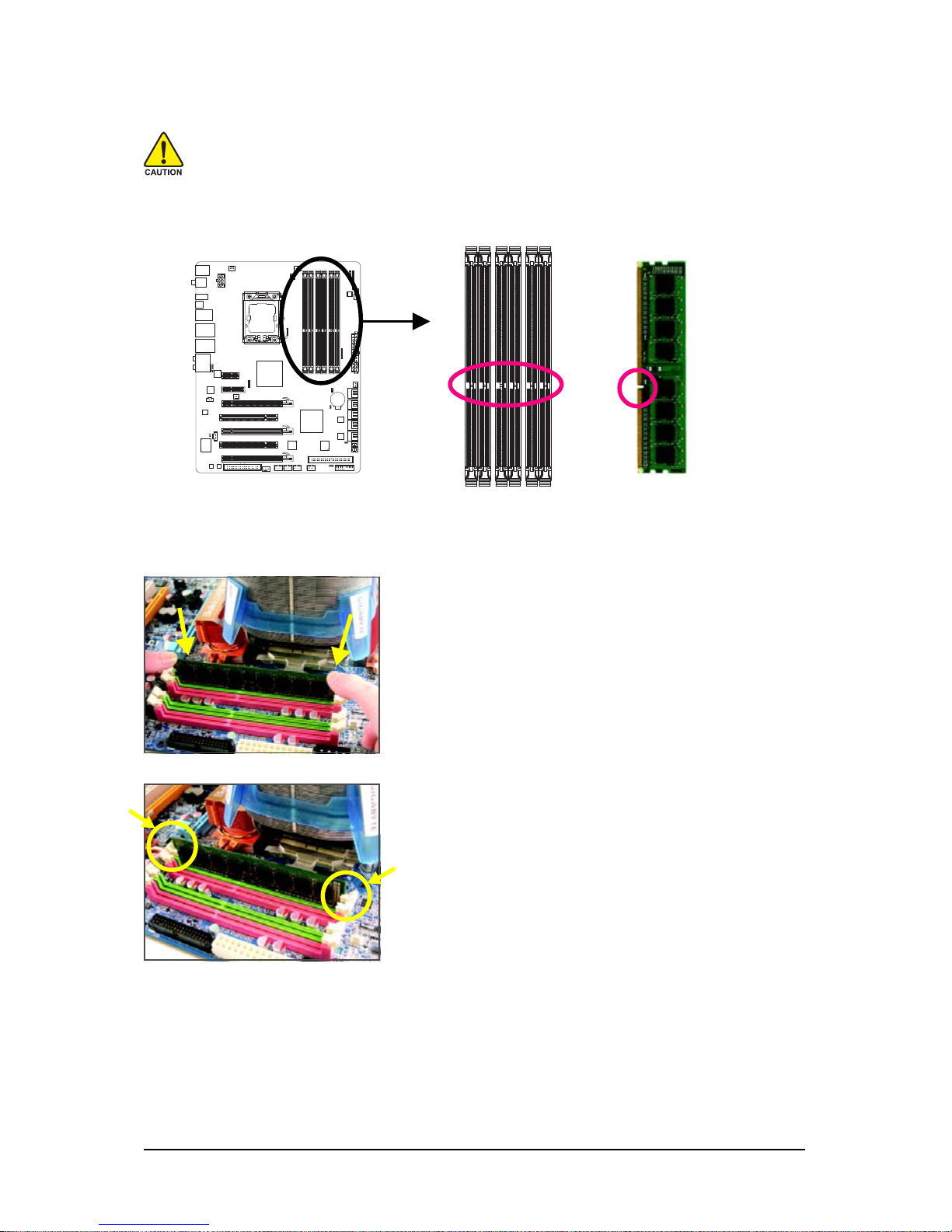
1-5-2 Installing a Memory
Before installing a memory module , make sure to turn off the computer and unplug
the power cord from the power outlet to prevent damage to the memory module.
DDR3 and DDR2 DIMMs are not compatible to each other or DDR DIMMs. Be sure to
install DDR3 DIMMs on this motherboard.
DDR3 DIMM
Step 1:
Note the orientation of the memory module. Spread the retaining
clips at both ends of the memory socket. Place the memory
module on the socket. As indicated in the picture on the left,
place your fingers on the top edge of the memory, push down
on the memory and insert it vertically into the memory socket.
Step 2:
The clips at both ends of the socket will snap into place when
the memory module is securely inserted.
A DDR3 memory module has a notch, so it can only fit in one direction. Follow the steps below to
correctly install your memory modules in the memory sockets.
Notch
Page 19
Hardware Installation- 19 -
1-6 Installing an Expansion Card
Read the following guidelines before you begin to install an expansion card:
• Make sure the motherboard supports the expansion card. Carefully read the manual that
came with your expansion card.
• Always turn off the computer and unplug the power cord from the power outlet before
installing an expansion card to prevent hardware damage.
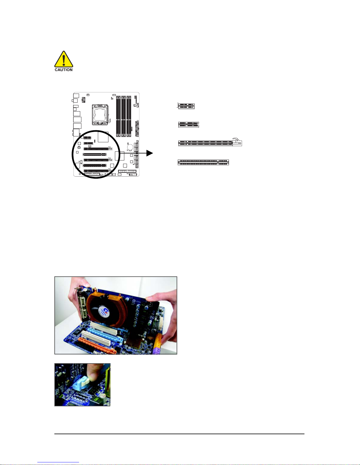
PCI Express x1 Slot
Follow the steps below to correctly install your expansion card in the expansion slot.
1. Locate an expansion slot that supports your card. Remove the metal slot cover from the chassis back panel.
2. Align the card with the slot, and press down on the card until it is fully seated in the slot.
3. Make sure the metal contacts on the card are completely inserted into the slot.
4. Secure the card's metal bracket to the chassis back panel with a screw.
5. After installing all expansion cards, replace the chassis cover(s).
6. Turn on your computer. If necessary, go to BIOS Setup to make any required BIOS changes for
your expansion card(s).
7. Install the driver provided with the expansion card in your operating system.
Example: Installing and Removing a PCI Express x16 Graphics Card:
• Installing a Graphics Card:
Gently push down on the top edge of the card
until it is fully inserted into the PCI Express slot.
Make sure the card is securely seated in the
slot and does not rock.
• Removing the Card:
Press the white latch at the end of the PCI Express slot to release the card
and then pull the card straight up from the slot.
PCI Express x4 Slot
PCI Express x16 Slot
PCI Slot
Page 20
GA-EX58-EXTREME Motherboard - 20 -
Figure 1
Figure 2
1-7 Setup of NVIDIA SLI (Scalable Link Interface)/ATI CrossFireX
Configuration
The SLI and CrossFireX technologies offer blistering graphics performance with the ability to bridge two
or three PCI ExpressTM graphics cards! This section provides instructions on configuring an SLI/
CrossFireX system.
A. Before You Begin
(Note) To set up a 3-Way CrossFireX configuration, install the bridge connector (optional) shown in
Figure 2.
1. Power Requirements:
Before installation, assure that the power supply you use is able to provide sufficient power to fully
support an SLI/CrossFireX configuration and other components in your system. We recommend a
power supply that provides at least 20A 5V and 12V current and a minimum of 600W (a 3-Way SLI/
CrossFireX platform requires minimum 1000W peak power). Note that the exact power requirements
will depend on your overall system configurations.
2. Supported Operation Systems:
Windows XP and Windows Vista operating systems are currently supported by the 2-Way SLI and
2-Way CrossFireX technologies.
Only Windows Vista operating systems are currently supported by the 3-Way SLI and 3-Way CrossFireX
technologies.
3. Installation Notices:
3-1 If you want to set up a single graphics card system, we recommend installing the graphics card
on the PCIEX16_1 slot.
3-2 To set up a 2-Way configuration, we recommend installing the graphics cards on the PCIEX16_1
and PCIEX16_2 slots. (Using graphics cards of identical brand and chips is recommended.)
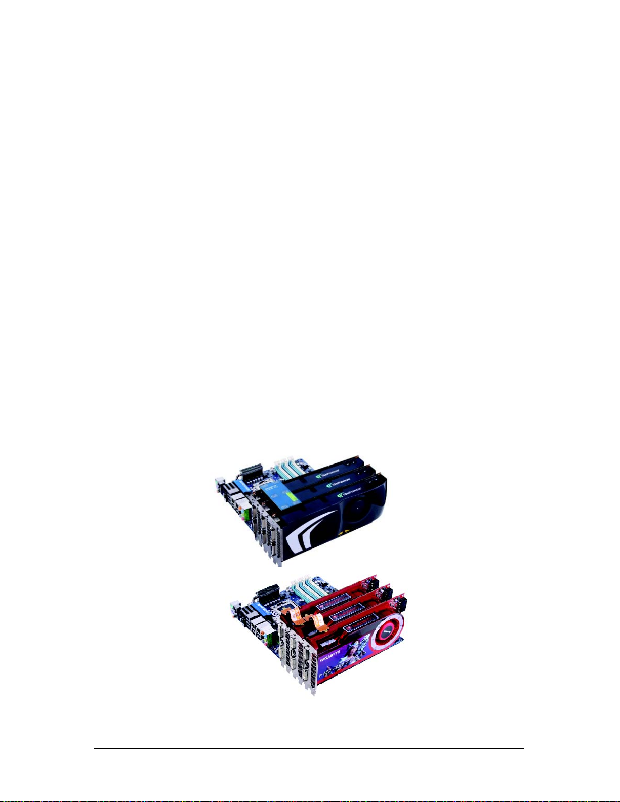
3-3 To set up a 3-Way SLI configuration (Figure 1) or a 3-Way CrossFireX configuration (Figure 2) , be
sure to use three identical graphics cards based on the following GPUs and a power supply of at
least 1000W. Current NVIDIA GPUs that support 3-Way SLI technology include the 8800 GTX,
8800 Ultra, 9800 GTX, GTX 260 and GTX 280. Current ATI GPUs that support 3-Way CrossFireX
technology include the Radeon HD 3800 series and Radeon HD 4800 series.
Page 21
Hardware Installation- 21 -
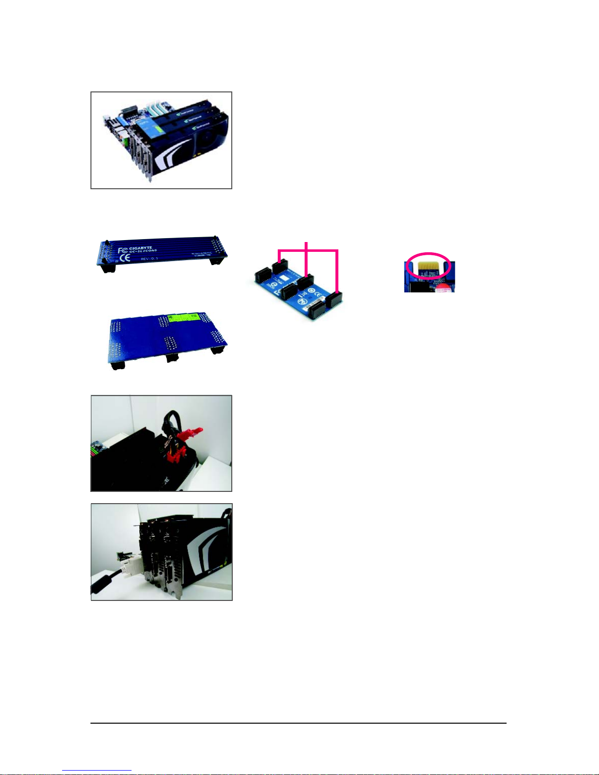
Gold edge connector on the top
of the graphics card
Female slots on the bridge connector
For 3-Way SLI System (GC-3SLI Bridge)
For 2-Way SLI System (GC-2SLI1 Bridge)
B. Connecting Three Graphics Cards:
(The procedure below demonstrates how to set up a 3-Way SLI system)
Step 2:
Connect power cables to the three graphics cards.
(Note) To set up a 2-Way SLI system, insert the GC-2SLI1
bridge into the SLI gold edge connectors on top of the two
graphics cards.
Step 1:
Observe the steps in "1-6 Installing an Expansion Card" and
install three SLI-ready graphics cards of the same model on the
PCIEX16_1, PCIEX16_2 and PCIEX_8 slots. Then, insert the
SLI bridge (the GC-3SLI ) in the SLI gold edge connectors on top
of the three cards. Make sure the mini female slots on the bridge
connector securely fit onto the SLI gold edge connetors of three
cards.
Step 3:
Plug the display cable into the graphics card on the PCIEX16_1
slot.
Page 22
GA-EX58-EXTREME Motherboard - 22 -
C. Configuring the Graphics Card Driver:
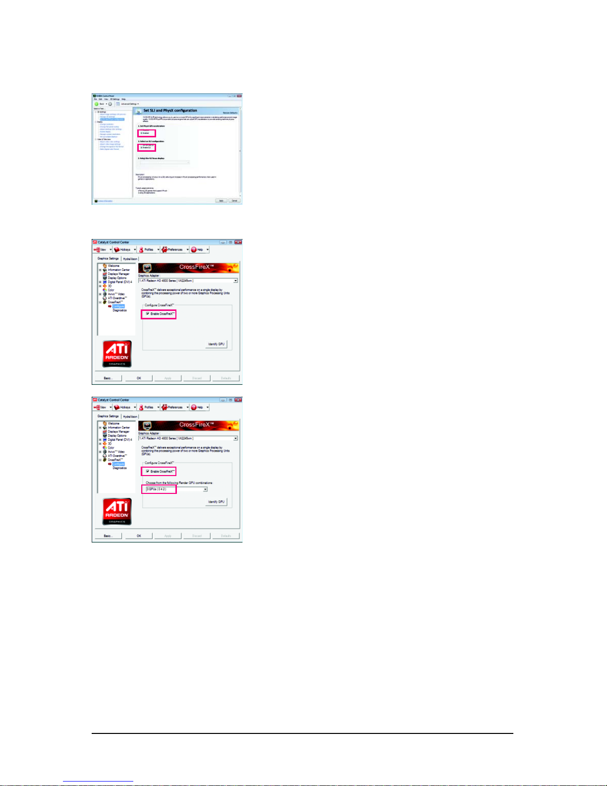
C-1 To enable SLI function
C-2 To enable CrossFireX function
(Note) Procedure for enabling SLI/CrossFireX technology may slightly differ by graphics cards.
Refer to the manual that came with your graphics cards for more information about enabling
SLI/CrossFireX technology.
For 2-Way/3-Way SLI:
After installing graphics card driver in the operating system, go
to the NVIDIA Control Panel. Browse to the SLI and Physx
configuration screen. Ensure SLI configuration and Physx is
enabled.
For 2-Way CrossFireX:
After installing graphics card driver in the operating system, go
to the Catalyst Control Center. Browse to the CrossFireX
screen and select the Enable CrossFire check box to complete the configuration.
For 3-Way CrossFireX:
Browse to the CrossFireX screen and select the Enable
CrossFire check box and also select 3 GPUS for the GPU
combination.
Page 23
Hardware Installation- 23 -
1- 8 Installing the SA TA Bracket
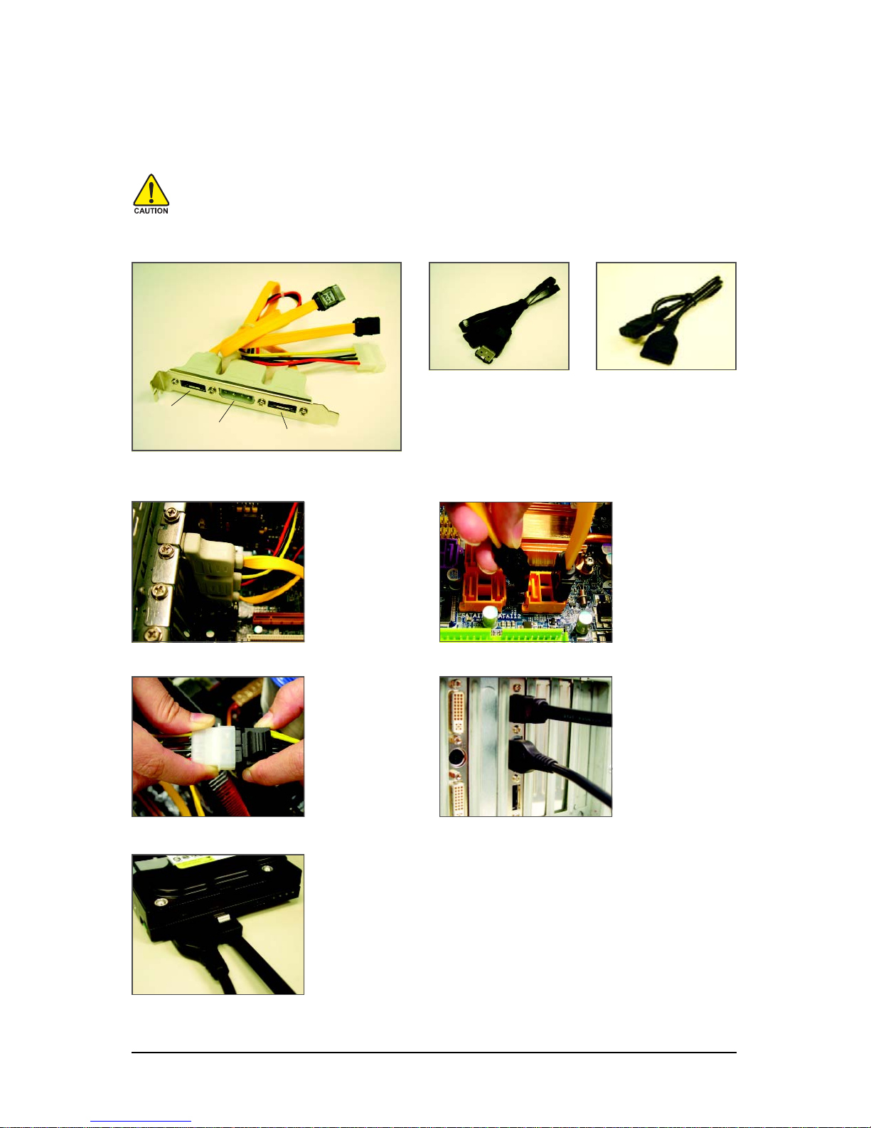
The SATA bracket includes one SATA bracket, one
SATA signal cable, and one SATA power cable.
Step 1:
Locate one free PCI
slot and secure the
SATA bracket to the
chassis back panel
with a screw.
Follow the steps below to install the SATA bracket:
Step 2:
Connect the SATA
cable from the bracket
to the SATA port on
your motherboard.
Step 3:
Connect the power
cable from the bracket
to the power supply.
Step 4:
Plug one end of the
SATA signal cable into
the external SA TA connector on the bracket.
Then attach the SATA
power cable to the
power connector on
the bracket.
The SATA bracket allows you to connect external SATA device(s) to your system by expanding the
internal SATA port(s) to the chassis back panel.
• Turn off your system and the power switch on the power supply before installing or
removing the SATA bracket and SATA power cable to prevent damage to hardware.
• Insert the SATA signal cable and SATA power cable securely into the corresponding connectors when installing.
Step 5:
Connect the other ends of the SATA signal cable and SATA power cable
to your SATA device. For SATA device in external enclosure, you only
need to connect the SATA signal cable. Before connecting the SATA signal
cable, make sure to turn off the power of the external enclosure.
SATA Bracket
External
SATA
Connector
Power
Connector
External SATA
Connector
SATA Signal Cable SATA Power Cable
Page 24
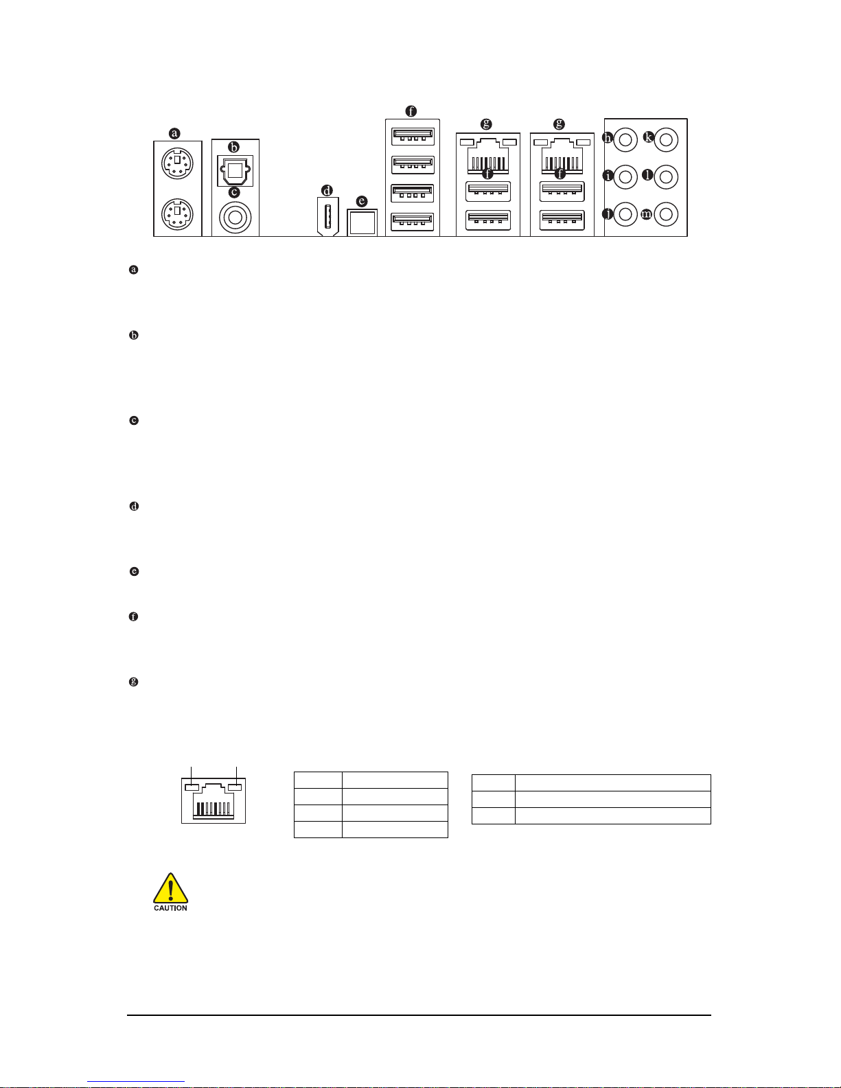
GA-EX58-EXTREME Motherboard - 24 -
• When removing the cable connected to a back panel connector, first remove the cable
from your device and then remove it from the motherboard.
• When removing the cable, pull it straight out from the connector. Do not rock it side to side
to prevent an electrical short inside the cable connector.
Activity LED
Connection/
Speed LED
LAN Port
Activity LED:
State Description
Blinking Data transmission or receiving is occurring
Off No data transmission or receiving is occurring
Connection/Speed LED:
State Description
Orange 1 Gbps data rate
Green 100 Mbps data rate
Off 10 Mbps data rate
1- 9 Back Panel Connectors
PS/2 Keyboard and PS/2 Mouse Port
Use the upper port (green) to connect a PS/2 mouse and the lower port (purple) to connect a PS/2
keyboard.
Optical S/PDIF Out Connector
This connector provides digital audio out to an external audio system that supports digital optical
audio. Before using this feature, ensure that your audio system provides an optical digital audio in
connector.
Coaxial S/PDIF Out Connector
This connector provides digital audio out to an external audio system that supports digital coaxial
audio. Before using this feature, ensure that your audio system provides a coaxial digital audio in
connector.
IEEE 1394a Port
The IEEE 1394 port supports the IEEE 1394a specification, featuring high speed, high bandwidth
and hotplug capabilities. Use this port for an IEEE 1394a device.
Clearing CMOS Switch
Press the clearing CMOS switch to clear CMOS values.
USB Port
The USB port supports the USB 2.0/1.1 specification. Use this port for USB devices such as an
USB keyboard/mouse, USB printer, USB flash drive and etc.
RJ-45 LAN Port
The Gigabit Ethernet LAN port provides Internet connection at up to 1 Gbps data rate. The following
describes the states of the LAN port LEDs.
clr
CMOS
Page 25

Hardware Installation- 25 -
Center/Subwoofer Speaker Out Jack (Orange)
Use this audio jack to connect center/subwoofer speakers in a 5.1/7.1-channel audio configuration.
Rear Speaker Out Jack (Black)
Use this audio jack to connect rear speakers in a 4/5.1/7.1-channel audio configuration.
Side Speaker Out Jack (Gray)
Use this audio jack to connect side speakers in a 7.1-channel audio configuration.
Line In Jack (Blue)
The default line in jack. Use this audio jack for line in devices such as an optical drive, walkman, etc.
Line Out Jack (Green)
The default line out jack. Use this audio jack for a headphone or 2-channel speaker. This jack can
be used to connect front speakers in a 4/5.1/7.1-channel audio configuration.
Mic In Jack (Pink)
The default Mic in jack. Microphones must be connected to this jack.
In addition to the default speakers settings, the ~ audio jacks can be reconfigured to
perform different functions via the audio software. Only microphones still MUST be connected to the default Mic in jack ( ). Refer to the instructions on setting up a 2/4/5.1/
7.1-channel audio configuration in Chapter 5, "Configuring 2/4/5.1/7.1-Channel Audio."
Page 26
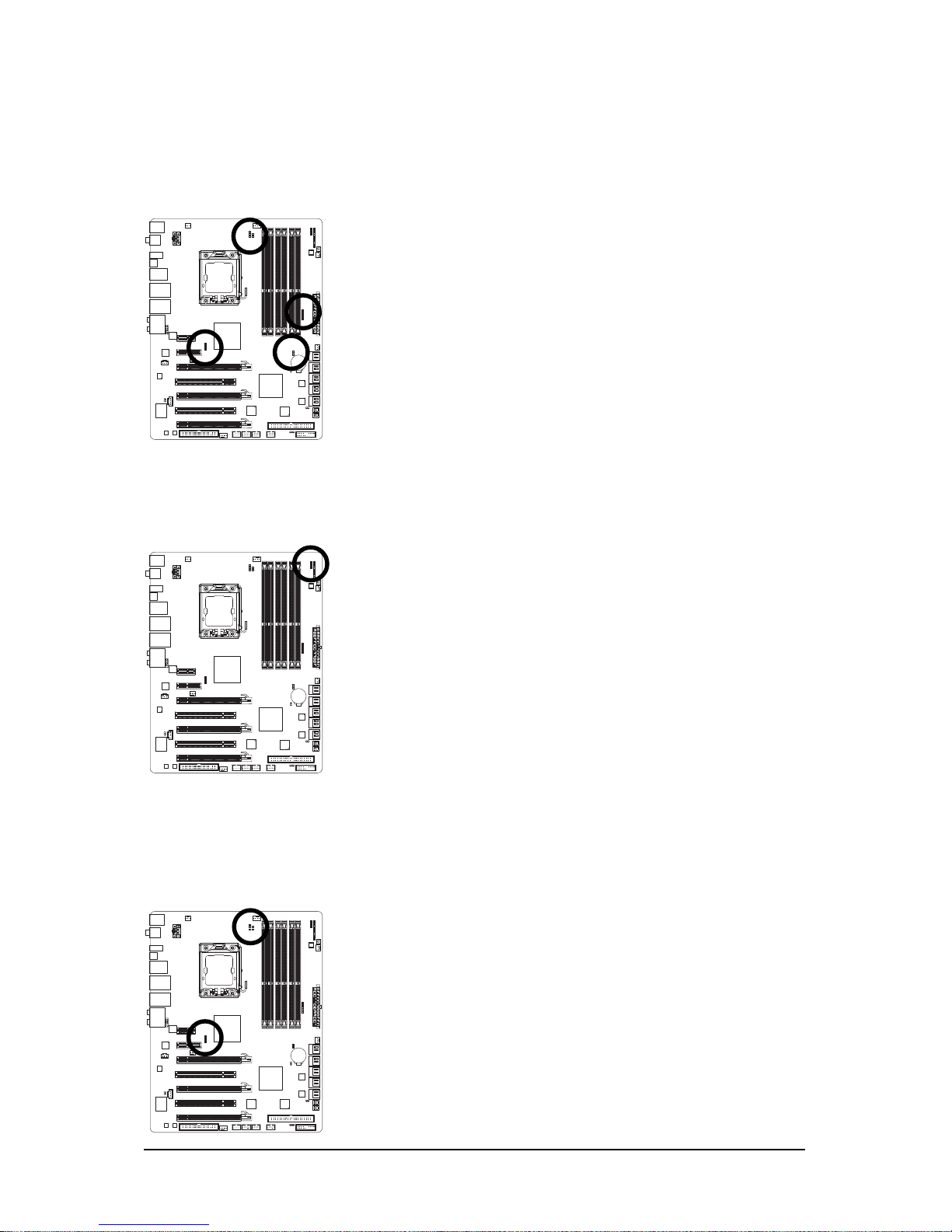
GA-EX58-EXTREME Motherboard - 26 -
1-10 Onboard LEDs and Switches
Overvoltage LEDs
This motherboard contains 4 sets of overvoltage LEDs which indicate the overvoltage level of the CPU,
memory, North Bridge, and South Bridge.
CPU (CPU Voltage)
Off: Normal condition
L1: Level 1 (Slight, green)
L2: Level 2 (Moderate, yellow)
L3: Level 3 (High, red)
Memory (DDR Voltage)
Off: Normal condition
L1: Level 1 (Slight, green)
L2: Level 2 (Moderate, yellow)
L3: Level 3 (High, red)
Overclock LEDs
The onboard CPU overclock LEDs indicate on which level the CPU is overclocked. The higher the overclock
level, the more the number of lighted LEDs.
Temperature Indicator LEDs
The two sets of temperature indicator LEDs indicate the temperature level of the CPU and North Bridge. The LEDs
are off when the temperature is below 60oC; the green LED lights up when the temperature is between 61~80oC;
the red LED is illuminated when the temperature exceeds 80oC.
CPU (CPU Temp)
Off: Below 60
o
C
L1: 61~ 80
o
C (green)
L2: Over 80
o
C (red)
North Bridge (NB Temp)
Off: Below 60oC
L1: 61~ 80
o
C (green)
L2: Over 80
o
C (red)
CPU (FREQUENCY LED)
Off: Normal condition
F_LED1~F_LED5 : Blue
North Bridge (NB Voltage)
Off: Normal condition
L1: Level 1 (Slight, green)
L2: Level 2 (Moderate, yellow)
L3: Level 3 (High, red)
South Bridge (SB Voltage)
Off: Normal condition
L1: Level 1 (Slight, green)
L2: Level 2 (Moderate, yellow)
L3: Level 3 (High, red)
Page 27
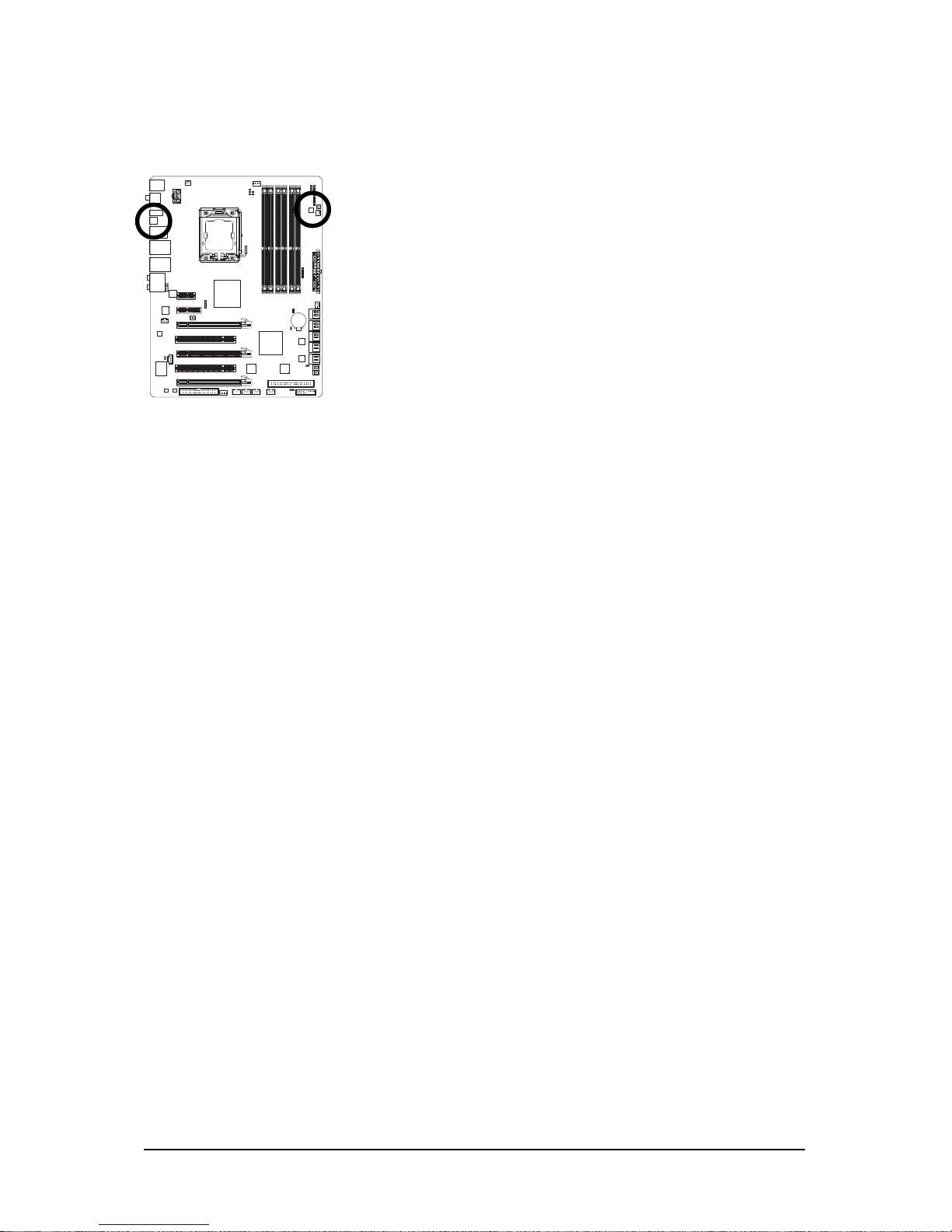
Hardware Installation- 27 -
Quick Switches
This motherboard has 3 quick switches: power switch, reset switch and clearing CMOS switch,
allowing users to quickly turn on/off or reset the system or clear the CMOS values.
PW_SW: Power switch
RST_SW: Reset switch
CMOS_SW: Clearing CMOS switch
Page 28
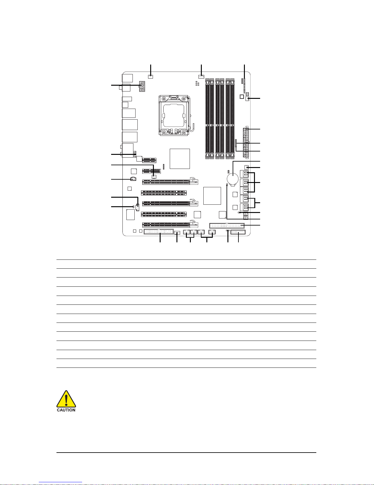
GA-EX58-EXTREME Motherboard - 28 -
1- 11 Internal Connectors
Read the following guidelines before connecting external devices:
• First make sure your devices are compliant with the connectors you wish to connect.
• Before installing the devices, be sure to turn off the devices and your computer. Unplug the
power cord from the power outlet to prevent damage to the devices.
• After installing the device and before turning on the computer, make sure the device cable
has been securely attached to the connector on the motherboard.
1) ATX_12V_2X
2) ATX
3) CPU_FAN
4) SYS_FAN1/2/3
5) PWR_FAN
6) NB_FAN
7) FDD
8) IDE
9) SATA2_0/1/2/3/4/5
10) GSATA2_0/1/2/3
11) PWR_LED
12) F_PANEL
13) F_AUDIO
14) CD_IN
15) SPDIF_I
16) SPDIF_O
17) F_USB1/F_USB2
18) F1_1394/F2_1394
19) CI
20) CLR_CMOS
21) B AT
22) PHASE_LED
23) NB PHASE LED
24) DDR PHASE LED
2
1
3
5
9
13
14
12
15
7
8
4 18
10
16
19
17
4
4
6
11
21
20
22
23
24
Page 29
Hardware Installation- 29 -
131
24
12
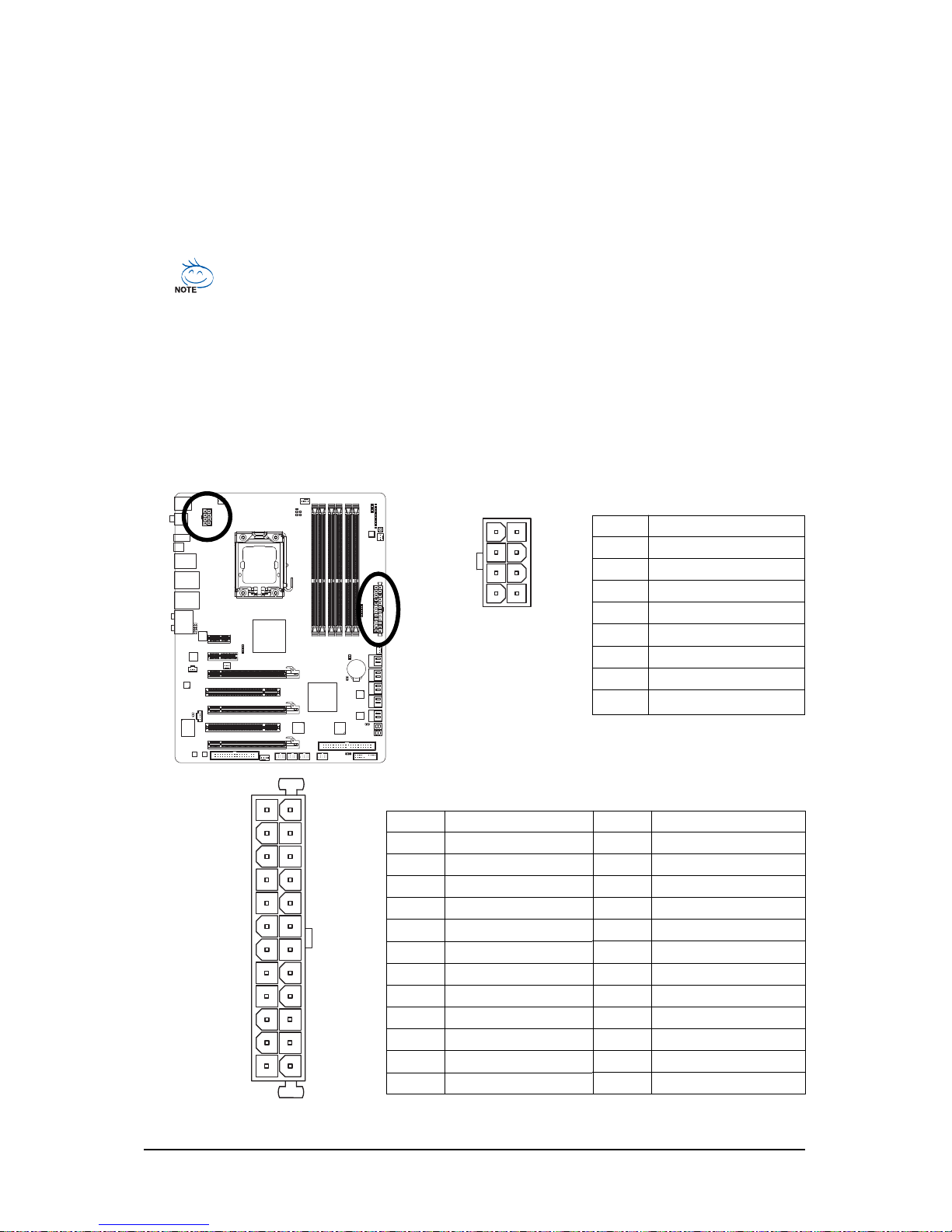
ATX_12V_2X
ATX
ATX :
ATX_12V_2X:
Pin No. Definition
1 GND (Only for 2x4 pin 12V)
2 GND ( Only for 2x4 pin 12V)
3 GND
4 GND
5 +12V (Only for 2x4 pin 12V)
6 +12V (Only for 2x4 pin 12V)
7 +12V
8 +12V
1
4
5
8
1/2) ATX_12V_2X/ATX (2x4 12V Power Connector and 2x12 Main Power Connector)
With the use of the power connector, the power supply can supply enough stable power to all the
components on the motherboard. Before connecting the power connector, first make sure the
power supply is turned off and all devices are properly installed. The power connector possesses
a foolproof design. Connect the power supply cable to the power connector in the correct orientation.
The 12V power connector mainly supplies power to the CPU. If the 12V power connector is not
connected, the computer will not start.
• Use of a power supply providing a 2x4 12V power connector is recommended by the
CPU manufacturer when using an Intel Extreme Edition CPU (130W).
• To meet expansion requirements, it is recommended that a power supply that can withstand
high power consumption be used (500W or greater). If a power supply is used that does not
provide the required power, the result can lead to an unstable or unbootable system.
• The power connectors are compatible with power supplies with 2x2 12V and 2x10 power
connectors. When using a power supply providing a 2x4 12V and a 2x12 power connector,
remove the protective covers from the 12V power connector and the main power connector on
the motherboard. Do not insert the power supply cables into pins under the protective covers
when using a power supply providing a 2x2 12V and a 2x10 power connector.
Pin No. Definition
13 3.3V
14 -12V
15 GND
16 PS_ON(soft On/Off)
17 GND
18 GND
19 GND
20 -5V
21 +5V
22 +5V
23 +5V (Only for 2x12 pin A TX)
24 GND (Only for 2x12 pin A TX)
Pin No. Definition
1 3.3V
2 3.3V
3 GND
4 +5V
5 GND
6 +5V
7 GND
8 Power Good
9 5V SB(stand by +5V)
10 +12V
1 1 +12V (Only for 2x12 pin ATX)
12 3.3V (Only for 2x12 pin ATX)
Page 30
GA-EX58-EXTREME Motherboard - 30 -
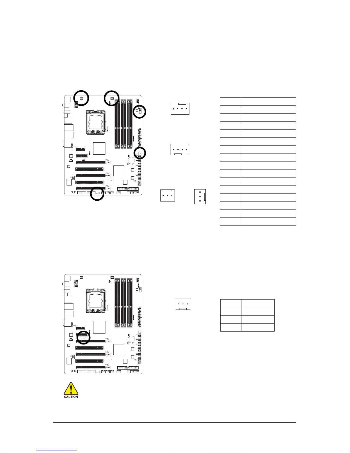
3/4/5) CPU_FAN / SYS_FAN1 / SYS_FAN2 / SYS_FAN3 / PWR_FAN (Fan Headers)
The motherboard has a 4-pin CPU fan header (CPU_FAN), a 4-pin (SYS_FAN2) and two 3-pin
(SYS_FAN1/SYS_FAN3) system fan headers, and a 3-pin power fan header (PWR_FAN). Most fan
headers possess a foolproof insertion design. When connecting a fan cable, be sure to connect it in
the correct orientation (the black connector wire is the ground wire). The motherboard supports CPU
fan speed control, which requires the use of a CPU fan with fan speed control design. For optimum
heat dissipation, it is recommended that a system fan be installed inside the chassis.
Pin No. Definition
1 GND
2 +12V
3 Sense
SYS_FAN1/PWR_FAN:
Pin No. Definition
1 GND
2 +12V / Speed Control
3 Sense
4 Speed Control
CPU_FAN:
Pin No. Definition
1 GND
2 Speed Control
3 Sense
4 +5V
SYS_FAN2:
SYS_FAN1/
PWR_FAN
SYS_FAN3
1
CPU_FAN
1
SYS_FAN2
1
1
6 ) NB_FAN (North Bridge Fan Header)
Connect the North Bridge fan cable to this header. The fan header has a foolproof insertion design.
When connecting a fan cable, be sure to connect it in the correct orientation. Most fans are designed
with color-coded power connector wires. A red power connector wire indicates a positive connection and requires a +12V voltage. The black connector wire is the ground wire.
• Be sure to connect fan cables to the fan headers to prevent your CPU, North Bridge and
system from overheating. Overheating may result in damage to the CPU/North Bridge or
the system may hang.
• These fan headers are not configuration jumper blocks. Do not place a jumper cap on the
headers.
Pin No. Definition
1 GND
2 +12V
3NC
1
Page 31
Hardware Installation- 31 -
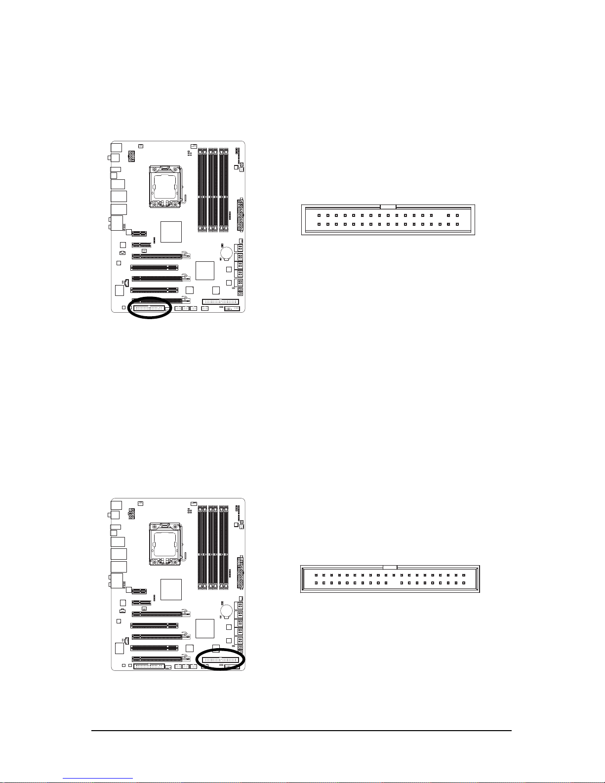
7) FDD (Floppy Disk Drive Connector)
This connector is used to connect a floppy disk drive. The types of floppy disk drives supported
are: 360 KB, 720 KB, 1.2 MB, 1.44 MB, and 2.88 MB. Before connecting a floppy disk drive, be
sure to locate pin 1 of the connector and the floppy disk drive cable. The pin 1 of the cable is
typically designated by a stripe of different color.
8 ) IDE (IDE Connector)
The IDE connector supports up to two IDE devices such as hard drives and optical drives. Before
attaching the IDE cable, locate the foolproof groove on the connector. If you wish to connect two IDE
devices, remember to set the jumpers and the cabling according to the role of the IDE devices (for
example, master or slave). (For information about configuring master/slave settings for the IDE
devices, read the instructions from the device manufacturers.)
1
2
33
34
2
1
40
39
Page 32
GA-EX58-EXTREME Motherboard - 32 -
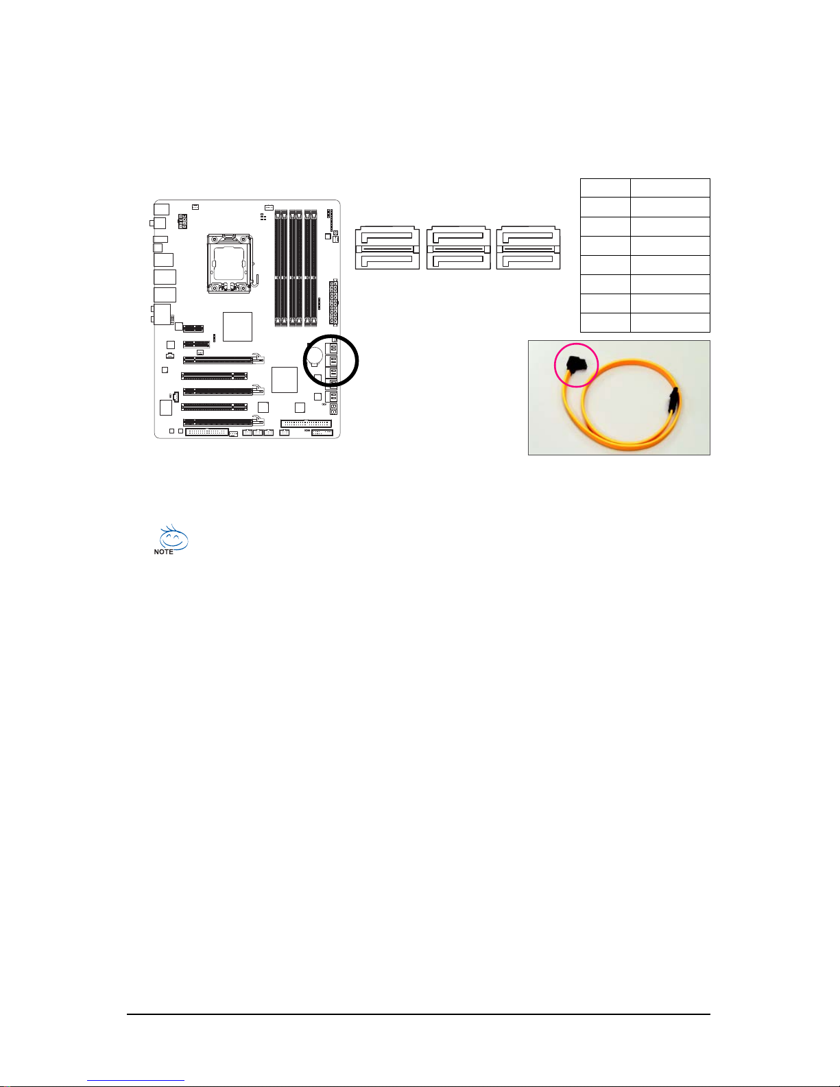
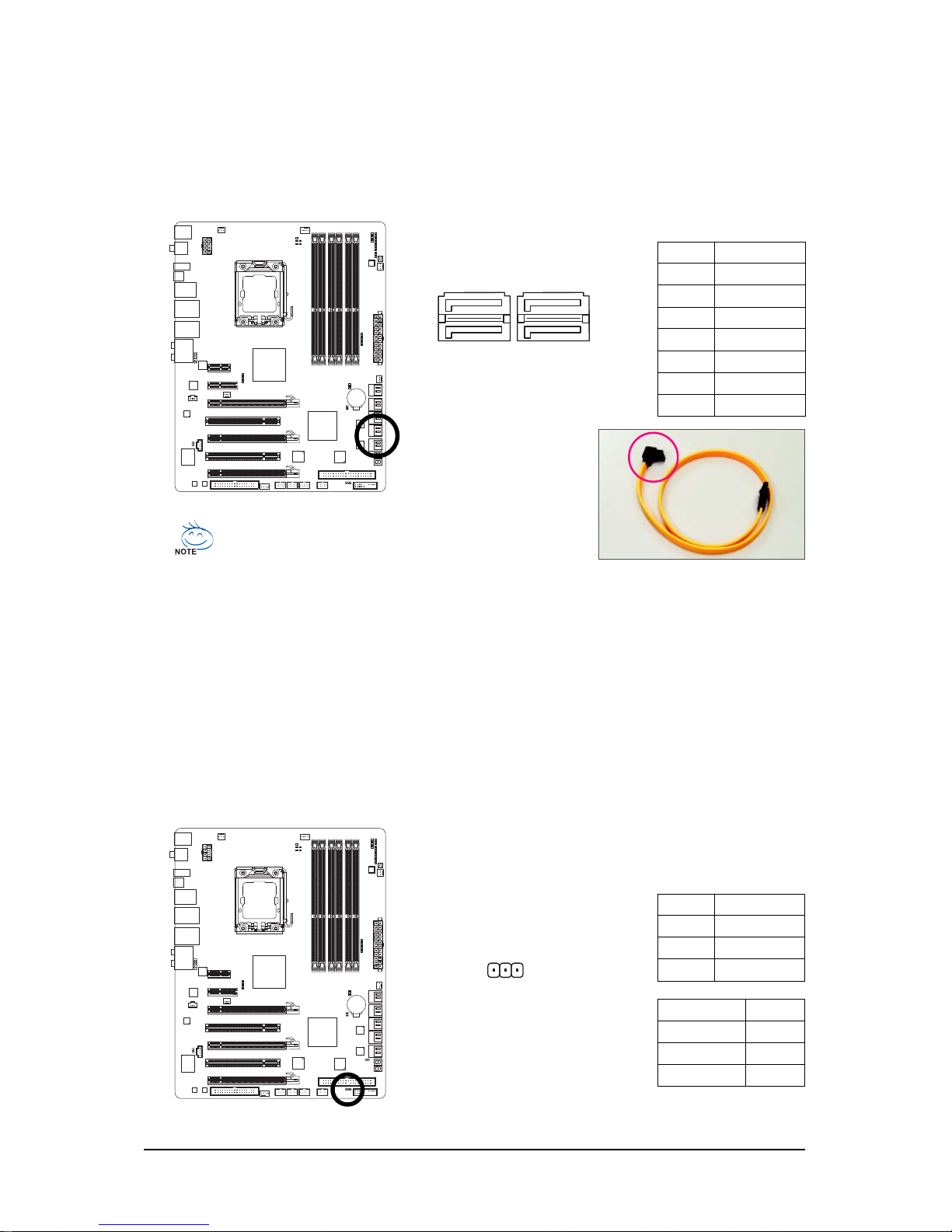
9) SATA2_0/1/2/3/4/5 (SATA 3Gb/s Connectors, Controlled by ICH10R, Blue)
The SATA connectors conform to SATA 3Gb/s standard and are compatible with SATA 1.5Gb/s
standard. Each SATA connector supports a single SATA device. The ICH10R controller supports
RAID 0, RAID 1, RAID 5 and RAID 10. Refer to Chapter 5, "Configuring SATA Hard Drive(s)," for
instructions on configuring a RAID array.
Pin No. Definition
1 GND
2TXP
3 TXN
4 GND
5 RXN
6 RXP
7 GND
• A RAID 0 or RAID 1 configuration requires at least two hard drives. If more than two hard
drives are to be used, the total number of hard drives must be an even number.
• A RAID 5 configuration requires at least three hard drives. (The total number of hard
drives does not have to be an even number.)
• A RAID 10 configuration requires at least four hard drives and the total number of hard
drives must be an even number.
Please connect the L-shaped end
of the SATA 3Gb/s cable to your
SATA hard drive.
SATA2_5
SATA2_4
SATA2_3
SATA2_2
SATA2_1
SATA2_0
1
1
7
7
Page 33
Hardware Installation- 33 -
10 ) GSA TA2_0/1/2/3 (SA T A 3Gb/s Connectors, Controlled by GIGABYTE SA T A2/JMB322, White)
The SATA connectors conform to SATA 3Gb/s standard and are compatible with SATA 1.5Gb/s
standard. Each SATA connector supports a single SATA device. The GIGABYTE SATA2/JMB322
controller supports RAID 0, RAID 1 and JBOD. Refer to Chapter 2, "Integrated Peripherals" and
Chapter 5, "Configuring SATA Hard Drive(s)," for instructions on configuring a RAID array.
Pin No. Definition
1 GND
2 TXP
3 TXN
4 GND
5 RXN
6 RXP
7 GND
A RAID 0 or RAID 1 configuration requires two hard
drives. The two hard drives must be connected to either
the GSATA2_0 and GS ATA2_1 connectors as an array
or to the GSATA2_2 and GSATA2_3 connectors.
GSATA2_3
GSATA2_2
GSATA2_1
GSATA2_0
1
1
7
7
Please connect the L-shaped end of the
SAT A 3Gb/s cable to your SA T A hard drive.
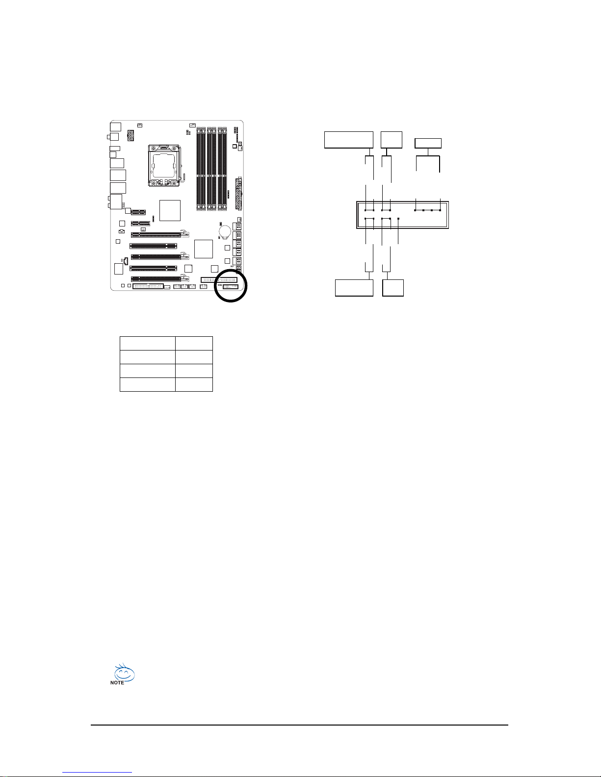
11) PWR_LED (System Power LED Header)
This header can be used to connect a system power LED on the chassis to indicate system power
status. The LED is on when the system is operating. The LED keeps blinking when the system is
in S1 sleep state. The LED is off when the system is in S3/S4 sleep state or powered off (S5).
Pin No. Definition
1 MPD+
2 MPD3 MPD-
System Status LED
S0 On
S1 Blinking
S3/S4/S5 Off
1
Page 34
GA-EX58-EXTREME Motherboard - 34 -
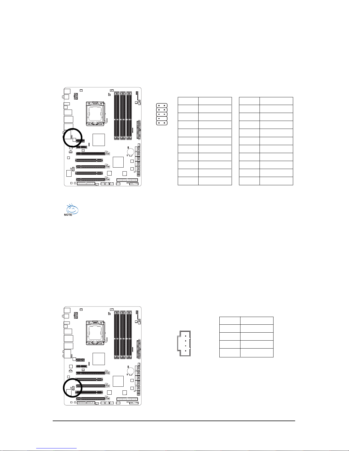
12) F_PANEL (Front Panel Header)
Connect the power switch, reset switch, speaker and system status indicator on the chassis front
panel to this header according to the pin assignments below. Note the positive and negative pins
before connecting the cables.
• PW (Power Switch, Red):
Connects to the power switch on the chassis front panel. You may configure the way to turn off
your system using the power switch (refer to Chapter 2, "BIOS Setup," "Power Management
Setup," for more information).
• SPEAK (Speaker, Orange):
Connects to the speaker on the chassis front panel. The system reports system startup status
by issuing a beep code. One single short beep will be heard if no problem is detected at system
startup. If a problem is detected, the BIOS may issue beeps in different patterns to indicate the
problem. Refer to Chapter 5, "Troubleshooting," for information about beep codes.
• HD (Hard Drive Activity LED, Blue)
Connects to the hard drive activity LED on the chassis front panel. The LED is on when the hard
drive is reading or writing data.
• RES (Reset Switch, Green):
Connects to the reset switch on the chassis front panel. Press the reset switch to restart the
computer if the computer freezes and fails to perform a normal restart.
• NC (Purple):
No connection
System Status LE D
S0 On
S1 Blinking
S3/S4/S5 Off
• MSG (Message/Power/Sleep LED, Yellow):
Connects to the power status indicator on the chassis front panel. The
LED is on when the system is operating. The LED keeps blinking when
the system is in S1 sleep state. The LED is off when the system is in
S3/S4 sleep state or powered off (S5).
The front panel design may differ by chassis. A front panel module mainly consists of
power switch, reset switch, power LED, hard drive activity LED, speaker and etc. When
connecting your chassis front panel module to this header, make sure the wire assignments and the pin assignments are matched correctly.
HD+
RES-
NC
SPEAK-
MSG+
PW+
Message/Power/
Sleep LED
Speaker
SPEAK+
Power
Switch
Hard Drive
Activity LED
Reset
Switch
19
20
HD-
RES+
MSG-
PW-
1
2
Page 35
Hardware Installation- 35 -
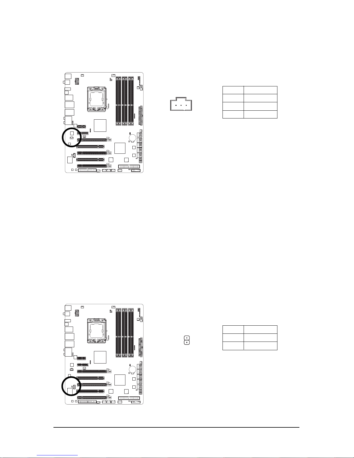
13) F_AUDIO (Front Panel Audio Header)
The front panel audio header supports Intel High Definition audio (HD) and AC'97 audio. You may
connect your chassis front panel audio module to this header. Make sure the wire assignments of
the module connector match the pin assignments of the motherboard header. Incorrect connection
between the module connector and the motherboard header will make the device unable to work
or even damage it.
14) CD_IN (CD In Connector, Black)
You may connect the audio cable that came with your optical drive to the header.
Pin No. Definition
1 CD-L
2 GND
3 GND
4 CD-R
For AC'97 Front Panel Audio:
• The front panel audio header supports HD audio by default. If your chassis provides an
AC'97 front panel audio module, refer to the instructions on how to activate AC'97 functioninality
via the audio software in Chapter 5, "Configuring 2/4/5.1/7.1-Channel Audio."
• Audio signals will be present on both of the front and back panel audio connections
simultaneously. If you want to mute the back panel audio (only supported when using an HD
front panel audio module), refer to Chapter 5, "Configuring 2/4/5.1/7.1-Channel Audio."
• Some chassis provide a front panel audio module that has separated connectors on each
wire instead of a single plug. For information about connecting the front panel audio
module that has different wire assignments, please contact the chassis manufacturer.
Pin No. Definition
1 MIC
2 GND
3 MIC Power
4NC
5 Line Out (R)
6NC
7NC
8 No Pin
9 Line Out (L)
10 NC
Pin No. Definition
1 MIC2_L
2 GND
3 MIC2_R
4 -ACZ_DET
5 LINE2_R
6 GND
7 FAUDIO_JD
8 No Pin
9 LINE2_L
10 GND
For HD Front Panel Audio:
1
2
910
1
Page 36
GA-EX58-EXTREME Motherboard - 36 -
15) SPDIF_I (S/PDIF In Header, Red)
This header supports digital S/PDIF in and can connect to an audio device that supports digital
audio out via an optional S/PDIF in cable. For purchasing the optional S/PDIF in cable, please
contact the local dealer.
16) SPDIF_O (S/PDIF Out Header)
This header supports digital S/PDIF out and connects a S/PDIF digital audio cable (provided by
expansion cards) for digital audio output from your motherboard to certain expansion cards like
graphics cards and sound cards. For example, some graphics cards may require you to use a
S/PDIF digital audio cable for digital audio output from your motherboard to your graphics card if
you wish to connect an HDMI display to the graphics card and have digital audio output from the
HDMI display at the same time. For information about connecting the S/PDIF digital audio cable,
carefully read the manual for your expansion card.
Pin No. Definition
1 SPDIFO
2 GND
Pin No. Definition
1 Power
2 SPDIFI
3 GND
1
1
Page 37
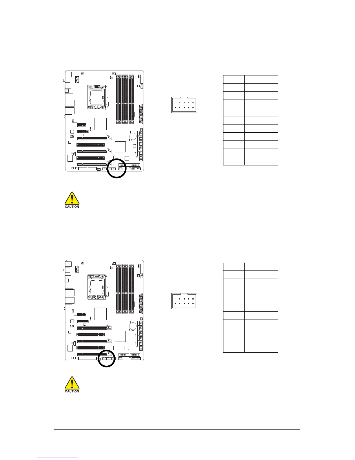
Hardware Installation- 37 -
18 ) F1_1394/F2_1394 (IEEE 1394a Headers, Gray)
The headers conform to IEEE 1394a specification. Each IEEE 1394a header can provide one IEEE
1394a port via an optional IEEE 1394a bracket. For purchasing the additional IEEE 1394a bracket(s),
please contact the local dealer.
Pin No. Definition
1TPA+
2TPA3 GND
4 GND
5 TPB+
6 TPB7 Power (12V)
8 Power (12V)
9 No Pin
10 GND
• Do not plug the USB bracket cable into the IEEE 1394a header.
• Prior to installing the IEEE 1394a bracket, be sure to turn off your computer and unplug
the power cord from the power outlet to prevent damage to the IEEE 1394a bracket.
• To connect an IEEE 1394a device, attach one end of the device cable to your computer
and then attach the other end of the cable to the IEEE 1394a device. Ensure that the cable
is securely connected.
17) F_USB1/F_USB2 (USB Headers, Yellow)
The headers conform to USB 2.0/1.1 specification. Each USB header can provide two USB ports
via an optional USB bracket. For purchasing the optional USB bracket, please contact the local
dealer.
Pin No. Definition
1 Power (5V)
2 Power (5V)
3 USB DX4 USB DY5 USB DX+
6 USB DY+
7 GND
8 GND
9 No Pin
10 NC
• Do not plug the IEEE 1394 bracket (2x5-pin) cable into the USB header.
• Prior to installing the USB bracket, be sure to turn off your computer and unplug the
power cord from the power outlet to prevent damage to the USB bracket.
10
9
2
1
10
9
2
1
Page 38
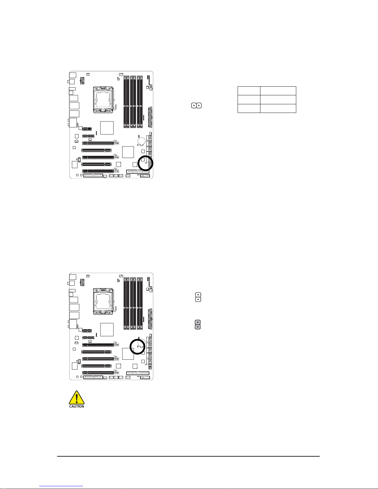
GA-EX58-EXTREME Motherboard - 38 -
19) CI (Chassis Intrusion Header)
This motherboard provides a chassis detection feature that detects if the chassis cover has been
removed. This function requires a chassis with chassis intrusion detection design.
Pin No. Definition
1 Signal
2 GND
Open: Normal
Short: Clear CMOS Values
20) CLR_CMOS (Clearing CMOS Jumper)
Use this jumper to clear the CMOS values (e.g. date information and BIOS configurations) and
reset the CMOS values to factory defaults. To clear the CMOS values, place a jumper cap on the
two pins to temporarily short the two pins or use a metal object like a screwdriver to touch the two
pins for a few seconds.
• Always turn off your computer and unplug the power cord from the power outlet before
clearing the CMOS values.
• After clearing the CMOS values and before turning on your computer, be sure to remove
the jumper cap from the jumper. Failure to do so may cause damage to the motherboard.
• After system restart, go to BIOS Setup to load factory defaults (select Load Optimized
Defaults) or manually configure the BIOS settings (refer to Chapter 2, "BIOS Setup," for
BIOS configurations).
1
Page 39
Hardware Installation- 39 -
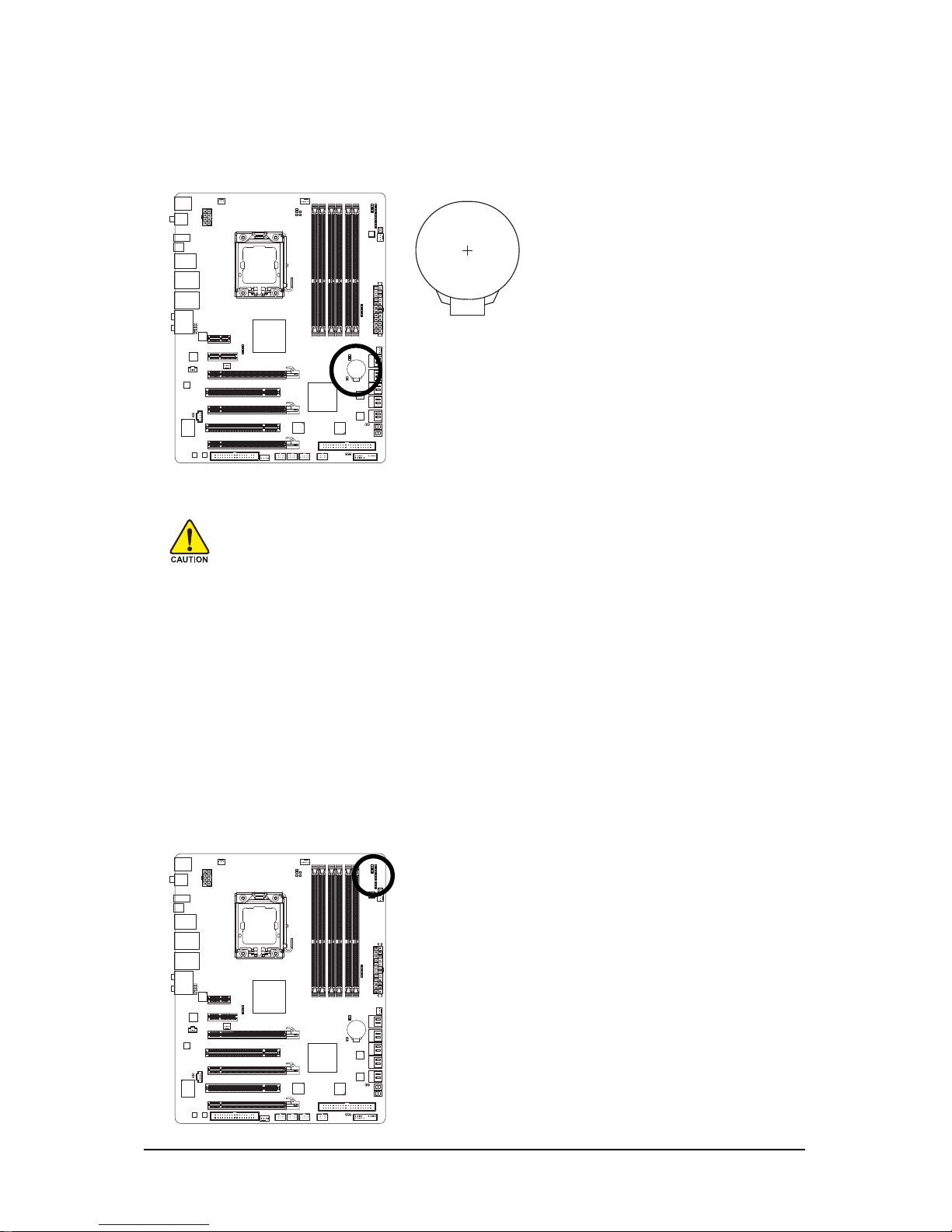
22) PHASE LED
The number of lighted LEDs indicates the CPU loading. The higher the CPU loading, the more the
number of lighted LEDs. To enable the Phase LED display function, please first enable Dynamic
Energy Saver Advanced. Refer to Chapter 4, "Dynamic Energy Saver Advanced," for more
details.
21) BAT (BATTERY)
The battery provides power to keep the values (such as BIOS configurations, date, and time
information) in the CMOS when the computer is turned off. Replace the battery when the battery
voltage drops to a low level, or the CMOS values may not be accurate or may be lost.
• Always turn off your computer and unplug the power cord before replacing the battery.
• Replace the battery with an equivalent one. Danger of explosion if the battery is replaced
with an incorrect model.
• Contact the place of purchase or local dealer if you are not able to replace the battery by
yourself or uncertain about the battery model.
• When installing the battery, note the orientation of the positive side (+) and the negative
side (-) of the battery (the positive side should face up).
• Used batteries must be handled in accordance with local environmental regulations.
You may clear the CMOS values by removing the battery:
1. Turn off your computer and unplug the power cord.
2. Gently remove the battery from the battery holder and wait for one minute.
(Or use a metal object like a screwdriver to touch the positive and
negative terminals of the battery holder, making them short for 5 seconds.)
3. Replace the battery.
4. Plug in the power cord and restart your computer.
Page 40
GA-EX58-EXTREME Motherboard - 40 -
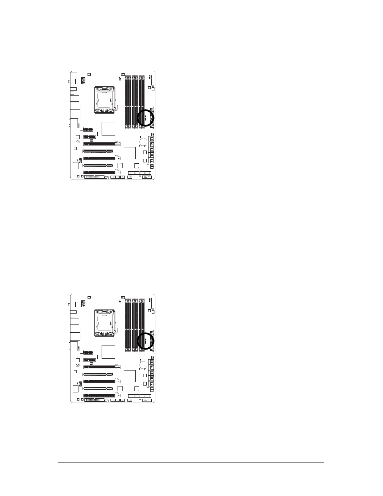
23) NB PHASE LED
The number of lighted LEDs indicates the North Bridge loading. The higher the North Bridge loading,
the more the number of lighted LEDs.
24) DDR PHASE LED
The number of lighted LEDs indicates the memory loading. The higher the memory loading, the
more the number of lighted LEDs.
Page 41
- 41 - BIOS Setup
Chapter 2 BIOS Setup
BIOS (Basic Input and Output System) records hardware parameters of the system in the CMOS on the
motherboard. Its major functions include conducting the Power-On Self-Test (POST) during system
startup, saving system parameters and loading operating system, etc. BIOS includes a BIOS Setup
program that allows the user to modify basic system configuration settings or to activate certain system
features. When the power is turned off, the battery on the motherboard supplies the necessary power
to the CMOS to keep the configuration values in the CMOS.
To access the BIOS Setup program, press the <Delete> key during the POST when the power is turned
on. To see more advanced BIOS Setup menu options, you can press <Ctrl> + <F1> in the main menu
of the BIOS Setup program.
To upgrade the BIOS, use either the GIGABYTE Q-Flash or @BIOS utility.
• Q-Flash allows the user to quickly and easily upgrade or back up BIOS without entering the
operating system.
• @BIOS is a Windows-based utility that searches and downloads the latest version of BIOS from the
Internet and updates the BIOS.
For instructions on using the Q-Flash and @BIOS utilities, refer to Chapter 4, "BIOS Update Utilities."
• Because BIOS flashing is potentially risky, if you do not encounter problems using the
current version of BIOS, it is recommended that you not flash the BIOS. To flash the BIOS,
do it with caution. Inadequate BIOS flashing may result in system malfunction.
• BIOS will emit a beep code during the POST. Refer to Chapter 5, "Troubleshooting," for the
beep codes description.
• It is recommended that you not alter the default settings (unless you need to) to prevent
system instability or other unexpected results. Inadequately altering the settings may result
in system's failure to boot. If this occurs, try to clear the CMOS values and reset the board
to default values. (Refer to the "Load Optimized Defaults" section in this chapter or introductions of the battery/clearing CMOS jumper in Chapter 1 for how to clear the CMOS values.)
Page 42
GA-EX58-EXTREME Motherboard - 42 -
2- 1 Startup Screen
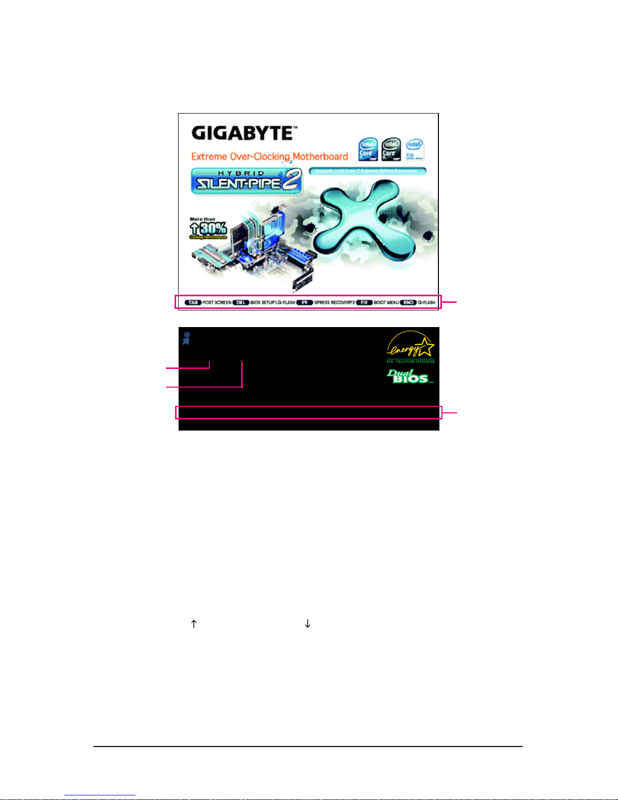
The following screens may appear when the computer boots.
A. The LOGO Screen (Default)
B. The POST Screen
Function Keys:
<TAB>: POST SCREEN
Press the <Tab> key to show the BIOS POST screen. To show the BIOS POST screen at system
startup, refer to the instructions on the Full Screen LOGO Show item on page 58.
<DEL>: BIOS SETUP\Q-Flash
Press the <Delete> key to enter BIOS Setup or to access the Q-Flash utility in BIOS Setup.
<F9>: XPRESS RECOVERY2
If you have ever entered Xpress Recovery2 to back up hard drive data using the driver disk, the
<F9> key can be used for subsequent access to XpressRecovery2 during the POST. For more
information, refer to Chapter 4, "Xpress Recovery2."
<F12>: BOOT MENU
Boot Menu allows you to set the first boot device without entering BIOS Setup. In Boot Menu, use
the up arrow key < > or the down arrow key< > to select the first boot device, then press <Enter>
to accept. To exit Boot Menu, press <Esc>. The system will directly boot from the device
configured in Boot Menu.
Note: The setting in Boot Menu is effective for one time only. After system restart, the device boot
order will still be based on BIOS Setup settings. You can access Boot Menu again to change the first
boot device setting as needed.
<End>: Q-FLASH
Press the <End> key to access the Q-Flash utility directly without having to enter BIOS Setup first.
Function Keys
Award Modular BIOS v6.00PG, An Energy Star Ally
Copyright (C) 1984-2008, Award Software, Inc.
EX58-EXTREME F1b
.
.
.
.
<DEL>: BIOS Setup <F9>: XpressRecovery2 <F12>: Boot Menu <End>: Qflash
10/21/2008-X58-ICH10-7A89QG02C-00
Motherboard Model
BIOS Version
Function Keys
Page 43
- 43 - BIOS Setup
2-2 The Main Menu
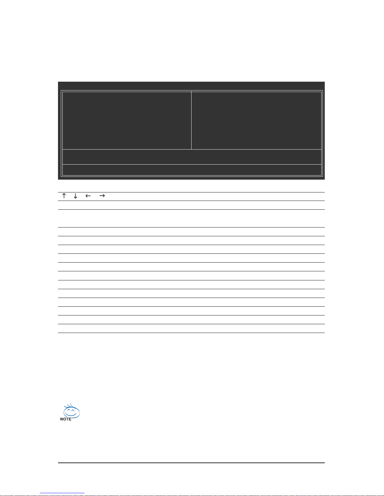
Once you enter the BIOS Setup program, the Main Menu (as shown below) appears on the screen. Use
arrow keys to move among the items and press <Enter> to accept or enter a sub-menu.
(Sample BIOS Version: F1b)
Main Menu Help
The onscreen description of a highlighted setup option is displayed on the bottom line of the Main Menu.
Submenu Help
While in a submenu, press <F1> to display a help screen (General Help) of function keys available for
the menu. Press <Esc> to exit the help screen. Help for each item is in the Item Help block on the right
side of the submenu.
BIOS Setup Program Function Keys
< >< >< >< > Move the selection bar to select an item
<Enter> Execute command or enter the submenu
<Esc> Main Menu: Exit the BIOS Setup program
Submenus: Exit current submenu
<Page Up> Increase the numeric value or make changes
<Page Down> Decrease the numeric value or make changes
<F1> Show descriptions of the function keys
<F2> Move cursor to the Item Help block on the right (submenus only)
<F5> Restore the previous BIOS settings for the current submenus
<F6> Load the Fail-Safe BIOS default settings for the current submenus
<F7> Load the Optimized BIOS default settings for the current submenus
<F8> Access the Q-Flash utility
<F9> Display system information
<F10> Save all the changes and exit the BIOS Setup program
<F11> Save CMOS to BIOS
<F12> Load CMOS from BIOS
• If you do not find the settings you want in the Main Menu or a submenu, press <Ctrl>+<F1>
to access more advanced options.
• When the system is not stable as usual, select the Load Optimized Defaults item to set
your system to its defaults.
• The BIOS Setup menus described in this chapter are for reference only and may differ by
BIOS version.
CMOS Setup Utility-Copyright (C) 1984-2008 Award Software
MB Intelligent Tweaker(M.I.T.)
Standard CMOS Features
Advanced BIOS Features
Integrated Peripherals
Power Management Setup
PC Health Status
Load Fail-Safe Defaults
Load Optimized Defaults
Set Supervisor Password
Set User Password
Save & Exit Setup
Exit Without Saving
ESC: Quit : Select Item F11: Save CMOS to BIOS
F8: Q-Flash F10: Save & Exit Setup F12: Load CMOS from BIOS
Time, Date, Hard Disk Type...
Page 44

GA-EX58-EXTREME Motherboard - 44 -
The Functions of the <F11> and <F12> keys (For the Main Menu Only)
F11 : Save CMOS to BIOS
This function allows you to save the current BIOS settings to a profile. You can create up to 8
profiles (Profile 1-8) and name each profile. First enter the profile name (to erase the default profile
name, use the SPACE key) and then press <Enter> to complete.
F12 : Load CMOS from BIOS
If your system becomes unstable and you have loaded the BIOS default settings, you can use this
function to load the BIOS settings from a profile created before, without the hassles of reconfiguring
the BIOS settings. First select the profile you wish to load, then press <Enter> to complete.
MB Intelligent Tweaker(M.I.T.)
Use this menu to configure the clock, frequency and voltages of your CPU, memory, etc.
Standard CMOS Features
Use this menu to configure the system time and date, hard drive types, floppy disk drive types,
and the type of errors that stop the system boot, etc.
Advanced BIOS Features
Use this menu to configure the device boot order, advanced features available on the CPU, and
the primary display adapter.
Integrated Peripherals
Use this menu to configure all peripheral devices, such as IDE, SATA, USB, integrated audio, and
integrated LAN, etc.
Power Management Setup
Use this menu to configure all the power-saving functions.
PC Health Status
Use this menu to see information about autodetected system/CPU temperature, system voltage
and fan speed, etc.
Load Fail-Safe Defaults
Fail-Safe defaults are factory settings for the most stable, minimal-performance system operations.
Load Optimized Defaults
Optimized defaults are factory settings for optimal-performance system operations.
Set Supervisor Password
Change, set, or disable password. It allows you to restrict access to the system and BIOS Setup.
A supervisor password allows you to make changes in BIOS Setup.
Set User Password
Change, set, or disable password. It allows you to restrict access to the system and BIOS Setup.
An user password only allows you to view the BIOS settings but not to make changes.
Save & Exit Setup
Save all the changes made in the BIOS Setup program to the CMOS and exit BIOS Setup.
(Pressing <F10> can also carry out this task.)
Exit Without Saving
Abandon all changes and the previous settings remain in effect. Pressing <Y> to the confirmation
message will exit BIOS Setup. (Pressing <Esc> can also carry out this task.)
Page 45
- 45 - BIOS Setup
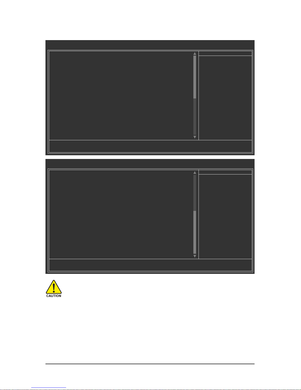
2-3 MB Intelligent Tweaker(M.I.T.)
(Note 1) This item appears only if you install a CPU that supports this feature.
(Note 2) This item appears only if you install a memory module that supports this feature.
Whether the system will work stably with the overclock/overvoltage settings you made is
dependent on your overall system configurations. Incorrectly doing overclock/overvoltage
may result in damage to CPU, chipset, or memory and reduce the useful life of these
components. This page is for advanced users only and we recommend you not to alter the
default settings to prevent system instability or other unexpected results. (Inadequately altering the settings may result in system's failure to boot. If this occurs, clear the CMOS values
and reset the board to default values.)
CMOS Setup Utility-Copyright (C) 1984-2008 Award Software
MB Intelligent Tweaker(M.I.T.)
CPU Clock Ratio
(Note 1)
[22X]
CPU Frequency 2.93GHz(133x22)
Advanced CPU Features [Press Enter]
QPI Link Speed [Auto]
QPI Link Speed 4.8GHz
UnCore & QPI Features [Press Enter]
Base Clock(BCLK) Control [Disabled]
x BCLK Frequency (Mhz) 133
Advanced Clock Control [Press Enter]
Performance Enhance [Turbo]
Extreme Memory Profile (X.M.P.)
(Note 2)
[Disabled]
System Memory Multiplier (SPD) [Auto]
Memory Frequency (Mhz) 1066 1066
DRAM Timing Selectable (SPD) [Auto]
Profile DDR Voltage 1.5V
Profile QPI Voltage 1.2V
>>>>> Channel A
x CAS Latency Time 8 Auto
x tRCD 7 Auto
: Move Enter: Select +/-/PU/PD: Value F10: Save ESC: Exit F1: General Help
F5: Previous Values F6: Fail-Safe Defaults F7: Optimized Defaults
Item Help
Menu Level
CMOS Setup Utility-Copyright (C) 1984-2008 Award Software
MB Intelligent Tweaker(M.I.T.)
: Move Enter: Select +/-/PU/PD: Value F10: Save ESC: Exit F1: General Help
F5: Previous Values F6: Fail-Safe Defaults F7: Optimized Defaults
x tRP 7 Auto
x tRAS 20 Auto
>>>>> Channel B
x CAS Latency Time 8 Auto
x tRCD 7 Auto
x tRP 7 Auto
x tRAS 20 Auto
>>>>> Channel C
x CAS Latency Time 8 Auto
x tRCD 7 Auto
x tRP 7 Auto
x tRAS 20 Auto
Advanced DRAM Features [Press Enter]
Voltage Types Normal Current
------------------------------------------------------------------
Load-Line Calibration [Disabled]
CPU Vcore 1.22500V [Auto]
QPI/Vtt Voltage 1.200V [Auto]
IOH Core 1.100V [Auto]
DRAM Voltage 1.500V [Auto]
Advanced Voltage Control [Press Enter]
Item Help
Menu Level
Page 46
GA-EX58-EXTREME Motherboard - 46 -
(Note) This item is present only if you install a CPU that supports this feature. For more information
about Intel CPUs' unique features, please visit Intel's website.
CPU Clock Ratio
(Note)
Allows you to alter the clock ratio for the installed CPU.
The item is present only if a CPU with unlocked clock ratio is installed.
CPU Frequency
Displays the current operating CPU frequency.
Intel(R) Turbo Boost Tech.
Allows you to determine whether to enable the Intel CPU Turbo Boost technology.
(Default: Enabled)
CPU Cores Enabled
(Note)
Allows you to determine whether to enable all CPU cores.
Enabled Enables all CPU cores. (Default)
1 Enables only one CPU core.
2 Enables only two CPU cores.
3 Enables only three CPU cores.
CPU Multi-Threading
(Note)
Allows you to determine whether to enable multi-threading technology when using an Intel
®
CPU that supports this function. This feature only works for operating systems that support multiprocessor mode. (Default: Enabled)
CPU Enhanced Halt (C1E)
(Note)
Enables or disables Intel® CPU Enhanced Halt (C1E) function, a CPU power-saving function in
system halt state. When enabled, the CPU core frequency and voltage will be reduced during
system halt state to decrease power consumption. (Default: Enabled)
C3/C6/C7 State Support
(Note)
Allows you to determine whether to let the CPU enter C3/C6/C7 mode in system halt state. When
enabled, the CPU core frequency and voltage will be reduced during system halt state to decrease
power consumption. The C3/C6/C7 state is a more enhanced power-saving state than C1.
(Default: Disabled)
CMOS Setup Utility-Copyright (C) 1984-2008 Award Software
Advanced CPU Features
: Move Enter: Select +/-/PU/PD: Value F10: Save ESC: Exit F1: General Help
F5: Previous Values F6: Fail-Safe Defaults F7: Optimized Defaults
CPU Clock Ratio
(Note)
[22X]
CPU Frequency 2.93GHz(133x22)
Intel(R) Turbo Boost Tech. [Enabled]
CPU Cores Enabled
(Note)
[All]
CPU Multi-Threading
(Note)
[Enabled]
CPU Enhanced Halt (C1E)
(Note)
[Enabled]
C3/C6/C7 State Support
(Note)
[Disabled]
CPU Thermal Monitor 2(TM2)
(Note)
[Enabled]
CPU EIST Function
(Note)
[Enabled]
Virtualization Technology
(Note)
[Enabled]
Bi-Directional PROCHOT
(Note)
[Enabled]
Item Help
Menu Level
*******
Advanced CPU Features*******
Page 47
- 47 - BIOS Setup
CPU Thermal Monitor
(Note)
Enables or disables Intel® CPU Thermal Monitor function, a CPU overheating protection function.
When enabled, the CPU core frequency and voltage will be reduced when the CPU is overheated.
(Default: Enabled)
CPU EIST Function
(Note)
Enables or disables Enhanced Intel SpeedStep Technology (EIST). Depending on CPU loading,
Intel® EIST technology can dynamically and effectively lower the CPU voltage and core frequency
to decrease average power consumption and heat production. (Default: Enabled)
Virtualization Technology
(Note)
Enables or disables Intel® Virtualization Technology. Virtualization enhanced by Intel® Virtualization
Technology will allow a platform to run multiple operating systems and applications in independent
partitions. With virtualization, one computer system can function as multiple virtual systems.
(Default: Enabled)
Bi-Directional PROCHOT
(Note)
Enabled When the CPU or chipset detects that an overheating is occurring, PROCHOT
signals will be emitted to lower CPU performance to decrease heat production.
(Default)
Disabled Only allows the CPU to detect whether an overheating is occurring to emit
PROCHOT signals.
CMOS Setup Utility-Copyright (C) 1984-2008 Award Software
UnCore & QPI Features
: Move Enter: Select +/-/PU/PD: Value F10: Save ESC: Exit F1: General Help
F5: Previous Values F6: Fail-Safe Defaults F7: Optimized Defaults
QPI Link Speed [Auto]
QPI Link Speed(MT) 4.8GHz
Uncore Frequency [Auto]
Uncore Frequency(MHz) 2667
Isochronous Support [Enabled]
Item Help
Menu Level
QPI Link Speed
Allows you to set the QPI Link speed. Options are: Auto (default), x36, x44, x48, Slow Mode.
UnCore Frequency
Allows you to set the UnCore frequency. Options are: Auto (default), x12~x48.
Isochronous Support
Determines whether to enable specific streams between the IOH and ICH. (Default: Enabled)
*******
UnCore & QPI Features *******
(Note) This item appears only if you install a CPU that supports this feature.
Page 48
GA-EX58-EXTREME Motherboard - 48 -
>>>>>
Standard Clock Control
Base Clock(BCLK) Control
Enables or disables the control of CPU base clock. Enabled will allow the BCLK Frequency
(Mhz)item below to be configurable. Note: If your system fails to boot after overclocking, please
wait for 20 seconds to allow for automated system reboot, or clear the CMOS values to reset the
board to default values. (Default: Disabled)
BCLK Frequency (Mhz)
Allows you to manually set the CPU base clock. The adjustable range is from 100 MHz to
1200 MHz. This item is configurable only if the Base Clock(BCLK) Control option is enabled.
Important It is highly recommended that the CPU frequency be set in accordance with the CPU
specifications.
PCI Express Frequency (Mhz)
Allows you to manually set the PCIe clock frequency. The adjustable range is from 90 MHz to
150 MHz. Auto sets the PCIe clock frequency to standard 100 MHz. (Default: Auto)
C.I.A.2
CPU Intelligent Accelerator 2 (C.I.A.2) is designed to automatically adjust CPU computing power
to maximize system performance. C.I.A.2 allows your system bus to be changed dynamically
based on CPU loading through the use of 5 preset states.
Note: System stability varies, depending on your system hardware components.
Disabled Disables the use of C.I.A.2. (Default)
Cruise Increases CPU frequency by 5% or 7% depending on CPU loading.
Sports Increases CPU frequency by 7% or 9% depending on CPU loading.
Racing Increases CPU frequency by 9% or 11% depending on CPU loading.
Turbo Increases CPU frequency by 15% or 17% depending on CPU loading.
Full Thrust Increases CPU frequency by 17% or 19% depending on CPU loading.
Warning: Before using C.I.A.2, please first verify the overclocking capability of your CPU.
As stability is highly dependent on system components, when system instability occurs after
overclocking, lower the overclocking ratio.
*******
Advanced Clock Control*******
CMOS Setup Utility-Copyright (C) 1984-2008 Award Software
Advanced Clock Control
: Move Enter: Select +/-/PU/PD: Value F10: Save ESC: Exit F1: General Help
F5: Previous Values F6: Fail-Safe Defaults F7: Optimized Defaults
>>>>> Sandard Clock Control
Base Clock(BCLK) Control [Disabled]
x BCLK Frequency (Mhz) 133 MHz
PCI Express Frequency (Mhz) [Auto]
C.I.A. 2 [Disabled]
>>>>> Advanced Clock Control
CPU Clock Drive [800mV]
PCI Express Clock Drive [900mV]
CPU Clock Skew [0ps]
MCH Clock Skew [0ps]
Item Help
Menu Level
Page 49
- 49 - BIOS Setup
>>>>>
Advanced Clock Control
CPU Clock Drive
Allows you to adjust the amplitude of the CPU and North Bridge clock.
Options are: 700mV, 800mV (default), 900mV, 1000mV.
PCI Express Clock Drive
Allows you to adjust the amplitude of the PCI Express and North Bridge clock.
Options are: 700mV, 800mV, 900mV (default), 1000mV.
CPU Clock Skew
Allows you to set the CPU clock prior to the North Bridge clock.
Options are: 0ps~750ps. (Default: 0ps)
MCH Clock Skew
Allows you to set the North Bridge clock prior to the CPU clock.
Options are: 0ps~750ps. (Default: 0ps)
*******
Advanced DRAM Features*******
CMOS Setup Utility-Copyright (C) 1984-2008 Award Software
Advanced DRAM Features
: Move Enter: Select +/-/PU/PD: Value F10: Save ESC: Exit F1: General Help
F5: Previous Values F6: Fail-Safe Defaults F7: Optimized Defaults
Performance Enhance [Turbo]
Extreme Memory Profile (X.M.P.)
(Note)
[Disabled]
System Memory Multiplier (SPD) [Auto]
Memory Frequency (Mhz) 1066 1066
DRAM Timing Selectable (SPD) [Auto]
Profile DDR Voltage 1.5V
Profile QPI Voltage 1.2V
>>>>> Channel A
Channel A Ti ming Settings [Press Enter]
Channel A Turnaround Settings [Press Enter]
>>>>> Channel B
Channel B Timing Settings [Press Enter]
Channel B Turnaround Settings [Press Enter]
>>>>> Channel C
Channel C Timing Settings [Press Enter]
Channel C Turnaround Settings [Press Enter]
Item Help
Menu Level
Performance Enhance
Allows the system to operate at three different performance levels.
Standard Lets the system operate at its basic performance level.
Turbo Lets the system operate at its good performance level. (Default)
Extreme Lets the system operate at its best performance level.
Extreme Memory Profile (X.M.P.)
(Note)
Allows the BIOS to read the SPD data on XMP memory module(s) to enhance memory performance
when enabled.
Disabled Disables this function. (Default)
Profile1 Uses Profile 1 settings.
(Note) This item appears only if you install a memory module that supports this feature.
Page 50
GA-EX58-EXTREME Motherboard - 50 -
System Memory Multiplier (SPD)
Allows you to set the system memory multiplier.Auto sets memory multiplier according to
memory SPD data. (Default: Auto)
Memory Frequency (Mhz)
The first memory frequency value is the normal operating frequency of the memory being used;
the second is the memory frequency that is automatically adjusted according to the BCLK
Frequency (Mhz) and System Memory Multiplier settings.
DRAM Timing Selectable (SPD)
Manual allows all DRAM Timing items below to be configurable.
Options are: Auto (default), Manual.
Profile DDR Voltage
When using a non-XMP memory module or Extreme Memory Profile (X.M.P.) is set to Disabled,
this item will display as 1.5V.
When Extreme Memory Profile (X.M.P.) is set to Profile1, this item will display the value based on
the SPD data on the XMP memory.
Profile QPI Voltage
The value displayed here is dependent on the CPU being used.
>>>>>
Channel A/B/C Timing Settings
>>>>>
Channel A/B/C Standard Timing Control
CAS Latency Time
Options are: Auto (default), 6~16.
tRCD
Options are: Auto (default), 1~15.
CMOS Setup Utility-Copyright (C) 1984-2008 Award Software
Channel A Timing Settings
: Move Enter: Select +/-/PU/PD: Value F10: Save ESC: Exit F1: General Help
F5: Previous Values F6: Fail-Safe Defaults F7: Optimized Defaults
>>>>> Channel A Standard Timing Control
x CAS Latency Time 6 Auto
x tRCD 6 Auto
x tRP 6 Auto
x tRAS 16 Auto
>>>>> Channel A Advanced Timing Control
x tRC 22 Auto
x tRRD 4 Auto
x tWTR 4 Auto
x tWR 8 Auto
x tRFC 48 Auto
x tRTP 3 Auto
x tFAW 13 Auto
x Command Rate (CMD) 1 Auto
>>>>> Channel A Misc Timing Control
x Round Trip Latency 51 Auto
Item Help
Menu Level
Page 51
- 51 - BIOS Setup
tRP
Options are: Auto (default), 1~15.
tRAS
Options are: Auto (default), 1~63.
>>>>>
Channel A/B/C Advanced Timing Control
tRC
Options are: Auto (default), 1~63.
tRRD
Options are: Auto (default), 1~15.
tWTR
Options are: Auto (default), 1~31.
tWR
Options are: Auto (default), 1~31.
tRFC
Options are: Auto (default), 1~255.
tRTP
Options are: Auto (default), 1~15.
tFA W
Options are: Auto (default), 1~63.
Command Rate(CMD)
Options are: Auto (default), 1~2.
>>>>>
Channel A/B/C Misc Timing Control
Round Trip Latency
Options are: Auto (default), 1~255.
>>>>>
Channel A/B/C Turnaround Settings
CMOS Setup Utility-Copyright (C) 1984-2008 Award Software
Channel A Turnaround Settings
: Move Enter: Select +/-/PU/PD: Value F10: Save ESC: Exit F1: General Help
F5: Previous Values F6: Fail-Safe Defaults F7: Optimized Defaults
>>>>> Channel A Writes Followed by Reads
x Different DIMMs 6 Auto
x Different Ranks 6 Auto
x On The Same Rank 6 Auto
>>>>> Channel A Reads Followed by Writes
x Different DIMMs 8 Auto
x Different Ranks 8 Auto
x On The Same Rank 8 Auto
>>>>> Channel A Reads Followed by Reads
x Different DIMMs 6 Auto
x Different Ranks 5 Auto
x On The Same Rank 1 Auto
>>>>> Channel A Writes Followed by Writes
x Different DIMMs 6 Auto
x Different Ranks 6 Auto
x On The Same Rank 1 Auto
Item Help
Menu Level
Page 52

GA-EX58-EXTREME Motherboard - 52 -
>>>>>
Channel A/B/C Writes Followed by Reads
Different DIMMS
Options are: Auto (default), 1~8.
Different Ranks
Options are: Auto (default), 1~8.
On The Same Ranks
Options are: Auto (default), 1~13.
>>>>>
Channel A/B/C Reads Followed by Writes
Different DIMMS
Options are: Auto (default), 1~15.
Different Ranks
Options are: Auto (default), 1~15.
On The Same Rank
Options are: Auto (default), 1~15.
>>>>>
Channel A/B/C Reads Followed by Reads
Different DIMMS
Options are: Auto (default), 1~8.
Different Ranks
Options are: Auto (default), 1~8.
On The Same Rank
Options are: Auto (default), 1~2.
>>>>>
Channel A/B/C Writes Followed by Writes
Different DIMMS
Options are: Auto (default), 1~8.
Different Ranks
Options are: Auto (default), 1~8.
On The Same Rank
Options are: Auto (default), 1~2.
Page 53
- 53 - BIOS Setup
>>>
CPU
Load-Line Calibration
Enables or disables Load-Line Calibration. Enabling this feature adjusts Vdroop, keeping the CPU
voltage more constant under light and heavy CPU load. Disabled sets the CPU voltage following
Intel specifications. (Default: Disabled)
CPU Vcore
The default is Auto.
QPI/Vtt Voltage
The default is Auto.
*******
Advanced Voltage Control*******
CMOS Setup Utility-Copyright (C) 1984-2008 Award Software
Advanced Voltage Control
: Move Enter: Select +/-/PU/PD: Value F10: Save ESC: Exit F1: General Help
F5: Previous Values F6: Fail-Safe Defaults F7: Optimized Defaults
Item Help
Menu Level
Voltage Types Normal Current
----------------------------------------------------------------->>> CPU
Load-Line Calibration [Disabled]
CPU Vcore 1.12500V [Auto]
QPI/Vtt Voltage 1.200V [Auto]
CPU PLL 1.800V [Auto]
>>> MCH/ICH
PCIE 1.500V [Auto]
QPI PLL 1.100V [Auto]
IOH Core 1.100V [Auto
ICH I/O 1.500V [Auto]
ICH Core 1.100V [Auto]
>>> DRAM
DRAM Voltage 1.500V [Auto]
DRAM Termination 0.750V [Auto]
Ch-A Data VRef. 0.750V [Auto]
Ch-B Data VRef. 0.750V [Auto]
Ch-C Data VRef. 0.750V [Auto]
CMOS Setup Utility-Copyright (C) 1984-2008 Award Software
Advanced Voltage Control
: Move Enter: Select +/-/PU/PD: Value F10: Save ESC: Exit F1: General Help
F5: Previous Values F6: Fail-Safe Defaults F7: Optimized Defaults
Item Help
Menu Level
Ch-A Address VRef. 0.750V [Auto]
Ch-B Address VRef. 0.750V [Auto]
Ch-C Address VRef. 0.750V [Auto]
Page 54

GA-EX58-EXTREME Motherboard - 54 -
CPU PLL
The default is Auto.
>>>
MCH/ICH
PCIE
The default is Auto.
QPI PLL
The default is Auto.
IOH Core
The default is Auto.
ICH I/O
The default is Auto.
ICH Core
The default is Auto.
>>>
DRAM
DRAM V oltage
The default is Auto.
DRAM Termination
The default is Auto.
Ch-A Data VRef.
The default is Auto.
Ch-B Data VRef.
The default is Auto.
Ch-C Data VRef.
The default is Auto.
Ch-A Address VRef.
The default is Auto.
Ch-B Address VRef.
The default is Auto.
Ch-C Address VRef.
The default is Auto.
Page 55
- 55 - BIOS Setup
2- 4 Standard CMOS Features
Date
Sets the system date. The date format is week (read-only), month, date and year. Select the
desired field and use the up arrow or down arrow key to set the date.
Time
Sets the system time. For example, 1 p.m. is 13:0:0. Select the desired field and use the up arrow
or down arrow key to set the time.
IDE Channel 0/1 Master/Slave
IDE HDD Auto-Detection
Press <Enter> to autodetect the parameters of the IDE/SATA device on this channel.
IDE Channel 0/1 Master/Slave
Configure your IDE/SATA devices by using one of the three methods below:
CMOS Setup Utility-Copyright (C) 1984-2008 Award Software
Standard CMOS Features
Date (mm:dd:yy) Mon, May 26 2008
Time (hh:mm:ss) 18:25:04
IDE Channel 0 Master [None]
IDE Channel 0 Slave [None]
IDE Channel 1 Master [None]
IDE Channel 1 Slave [None]
IDE Channel 2 Master [None]
IDE Channel 3 Master [None]
IDE Channel 4 Master [None]
IDE Channel 4 Slave [None]
IDE Channel 5 Master [None]
IDE Channel 5 Slave [None]
Drive A [1.44M, 3.5"]
Floppy 3 Mode Support [Disabled]
Halt On [All, But Keyboard]
: Move Enter: Select +/-/PU/PD: Value F10: Save ESC: Exit F1: General Help
F5: Previous Values F6: Fail-Safe Default F7: Optimized Defaults
Item Help
Menu Level
CMOS Setup Utility-Copyright (C) 1984-2008 Award Software
Standard CMOS Features
Base Memory 640K
Extended Memory 510M
Total Memory 512M
: Move Enter: Select +/-/PU/PD: Value F10: Save ESC: Exit F1: General Help
F5: Previous Values F6: Fail-Safe Default F7: Optimized Defaults
Item Help
Menu Level
Page 56
GA-EX58-EXTREME Motherboard - 56 -
• Auto Lets BIOS automatically detect IDE/SATA devices during the POST. (Default)
• None If no IDE/SATA devices are used, set this item to None so the system will
skip the detection of the device during the POST for faster system startup.
• Manual Allows you to manually enter the specifications of the hard drive when the
hard drive access mode is set to CHS.
Access Mode Sets the hard drive access mode. Options are: Auto (default), CHS, LBA, Large.
IDE Channel 2/3 Master, IDE Channel 4/5 Master/Slave
IDE Auto-Detection
Press <Enter> to autodetect the parameters of the IDE/SATA device on this channel.
Extended IDE Drive
Configure your IDE/SATA devices by using one of the two methods below:
• Auto Lets BIOS automatically detect IDE/SATA devices during the POST. (Default)
• None If no IDE/SATA devices are used, set this item to None so the system will
skipthe detection of the device during the POST for faster system startup.
Access Mode Sets the hard drive access mode. Options are: Auto (default), Large.
The following fields display your hard drive specifications. If you wish to enter the parameters
manually, refer to the information on the hard drive.
Capacity Approximate capacity of the currently installed hard drive.
Cylinder Number of cylinders.
Head Number of heads.
Precomp Write precompensation cylinder.
Landing Zone Landing zone.
Sector Number of sectors.
Drive A
Allows you to selects the type of floppy disk drive installed in your system. If you do not install a
floppy disk drive, set this item to None. Options are: None, 360K/5.25", 1.2M/5.25", 720K/3.5",
1.44M/3.5", 2.88M/3.5".
Floppy 3 Mode Support
Allows you to specify whether the installed floppy disk drive is 3-mode floppy disk drive, a
Japanese standard floppy disk drive. Options are: Disabled (default), Drive A.
Halt On
Allows you to determine whether the system will stop for an error during the POST.
No Errors The system boot will not stop for any error.
All Errors Whenever the BIOS detects a non-fatal error the system boot will stop.
All, But Keyboard The system boot will not stop for a keyboard error but stop for all other
errors. (Default)
All, But Diskette The system boot will not stop for a floppy disk drive error but stop for all
other errors.
All, But Disk/Key The system boot will not stop for a keyboard or a floppy disk drive error but
it will stop for all other errors.
Memory
These fields are read-only and are determined by the BIOS POST.
Base Memory Also called conventional memory. Typically, 640 KB will be reserved for
the MS-DOS operating system.
Extended Memory The amount of extended memory.
Total Memory The total amount of memory installed on the system.
Page 57
- 57 - BIOS Setup
2- 5 Advanced BIOS Features
Hard Disk Boot Priority
Specifies the sequence of loading the operating system from the installed hard drives. Use the up
or down arrow key to select a hard drive, then press the plus key <+> (or <PageUp>) or the minus
key <-> (or <PageDown>) to move it up or down on the list. Press <Esc> to exit this menu when
finished.
First/Second/Third Boot Device
Specifies the boot order from the available devices. Use the up or down arrow key to select a
device and press <Enter> to accept. Options are: Floppy, LS120, Hard Disk, CDROM, ZIP,
USB-FDD, USB-ZIP, USB-CDROM, USB-HDD, Legacy LAN, Disabled.
Password Check
Specifies whether a password is required every time the system boots, or only when you enter
BIOS Setup. After configuring this item, set the password(s) under the Set Supervisor/User
Password item in the BIOS Main Menu.
Setup A password is only required for entering the BIOS Setup program. (Default)
System A password is required for booting the system and for entering the BIOS Setup
program.
HDD S.M.A.R.T. Capability
Enables or disables the S.M.A.R.T. (Self Monitoring and Reporting Technology) capability of your
hard drive. This feature allows your system to report read/write errors of the hard drive and to
issue warnings when a third party hardware monitor utility is installed. (Default: Disabled)
Limit CPUID Max. to 3
(Note)
Allows you to determine whether to limit CPUID maximum value. Set this item to Disabled for
Windows XP operating system; set this item to Enabled for legacy operating system such as
Windows NT4.0. (Default: Disabled)
(Note) This item is present only if you install a CPU that supports this feature. For more information
about Intel CPUs' unique features, please visit Intel's website.
CMOS Setup Utility-Copyright (C) 1984-2008 Award Software
Advanced BIOS Features
Hard Disk Boot Priority [Press Enter]
First Boot Device [Floppy]
Second Boot Device [Hard Disk]
Third Boot Device [CDROM]
Password Check [Setup]
HDD S.M.A.R.T. Capability [Disabled]
Limit CPUID Max. to 3
(Note)
[Disabled]
No-Execute Memory Protect
(Note)
[Enabled]
Delay for HDD (Secs) [0]
Full Screen LOGO Show [Enabled]
Init Display First [PCI]
: Move Enter: Select +/-/PU/PD: Value F10: Save ESC: Exit F1: General Help
F5: Previous Values F6: Fail-Safe Defaults F7: Optimized Defaults
Item Help
Menu Level
Page 58
GA-EX58-EXTREME Motherboard - 58 -
(Note) This item is present only if you install a CPU that supports this feature. For more information
about Intel CPUs' unique features, please visit Intel's website.
No-Execute Memory Protect
(Note)
Enables or disables Intel® Execute Disable Bit function. This function may enhance protection for
the computer, reducing exposure to viruses and malicious buffer overflow attacks when working
with its supporting software and system. (Default: Enabled)
Delay For HDD (Secs)
Allows you to set a delay time for the BIOS to initialize the hard drive as the system boots up.
The adjustable range is from 0 to 15 seconds. (Default: 0)
Full Screen LOGO Show
Allows you to determine whether to display the GIGABYTE Logo at system startup. Disabled
displays normal POST message. (Default: Enabled)
Init Display First
Specifies the first initiation of the monitor display from the installed PCI graphics card or
PCI Express graphics card.
PCI Sets the PCI graphics card as the first display. (Default)
PEG Sets PCI Express graphics card on the first PCI Express x16 slot (PCIEX16_1)
as the first display.
PEG2 Sets PCI Express graphics card on the second PCI Express x16 slot (PCIEX16_2)
as the first display.
PEG3 Sets PCI Express graphics card on the PCI Express x8 slot (PCIEX8_1) as the
first display.
PEG4 Sets PCI Express graphics card on the PCI Express x4 slot (PCIEX4_1) as
the first display.
Page 59
- 59 - BIOS Setup
2- 6 Integrated Peripherals
SATA RAID/AHCI Mode
Enables or disables RAID for the SATA controllers or configures the SATA controllers to AHCI mode.
Disabled Disables RAID for the SATA controllers and configures the SATA controllers to
PATA mode. (Default)
AHCI Configures the SATA controllers to AHCI mode. Advanced Host Controller
Interface (AHCI) is an interface specification that allows the storage driver to
enable advanced Serial ATA features such as Native Command Queuing and
hot plug.
RAID Enables RAID for the SATA controllers.
SATA Port0-3 Native Mode
Specifies the operating mode of the integrated SATA controllers.
Disabled Allows the SATA controllers to operate in Legacy IDE mode.
In Legacy mode the SATA controllers use dedicated IRQs that cannot be shared
with other device. Set this option to Disabled if you wish to install operating
systems that do not support Native mode. (Default)
Enabled Allows the SATA controllers to operate in Native IDE mode.
Enable Native IDE mode if you wish to install operating systems that support
Native mode.
USB 1.0 Controller
Enables or disables the integrated USB 1.0 controller. (Default: Enabled)
Disabled will turn off all of the USB functionalities below.
USB 2.0 Controller
Enables or disables the integrated USB 2.0 controller. (Default: Enabled)
USB Keyboard Function
Allows USB keyboard to be used in MS-DOS. (Default: Disabled)
USB Mouse Function
Allows USB mouse to be used in MS-DOS. (Default: Disabled)
CMOS Setup Utility-Copyright (C) 1984-2008 Award Software
Integrated Peripherals
SATA RAID/AHCI Mode [Disabled]
SATA Port0-3 Native Mode [Disabled]
USB 1.0 Controller [Enabled]
USB 2.0 Controller [Enabled]
USB Keyboard Function [Disabled]
USB Mouse Function [Disabled]
USB Storage Function [Enabled]
Azalia Codec [Auto]
Onboard H/W 1394 [Enabled]
Onboard H/W LAN1 [Enabled]
Onboard H/W LAN2 [Enabled]
Green LAN [Disabled]
SMART LAN1 [Press Enter]
SMART LAN2 [Press Enter]
Onboard LAN1 Boot ROM [Disabled]
Onboard LAN2 Boot ROM [Disabled]
Onboard SATA/IDE Device [Enabled]
Onboard SATA/IDE Ctrl Mode [IDE]
Smart Backup [Press Enter]
: Move Enter: Select +/-/PU/PD: Value F10: Save ESC: Exit F1: General Help
F5: Previous Values F6: Fail-Safe Defaults F7: Optimized Defaults
Item Help
Menu Level
Page 60
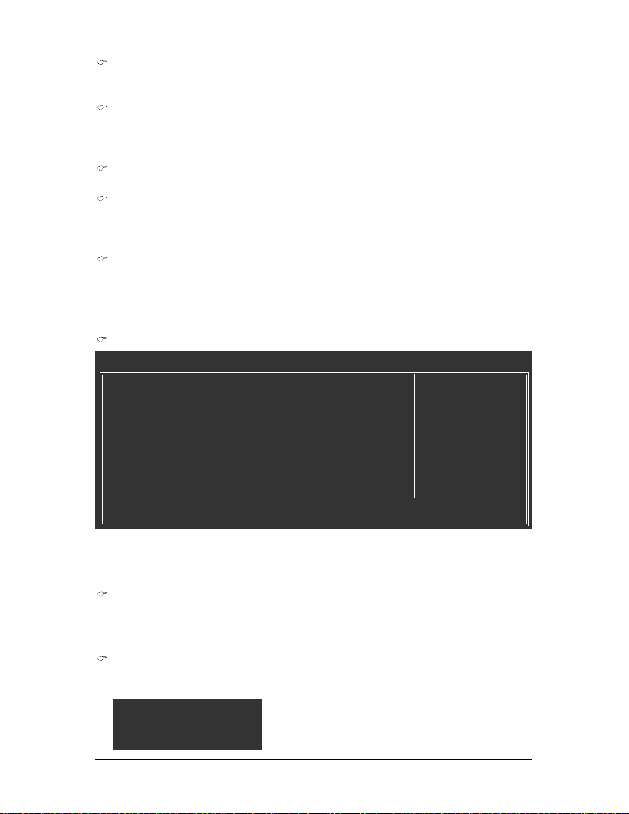
GA-EX58-EXTREME Motherboard - 60 -
USB Storage Function
Determines whether to detect USB storage devices, including USB flash drives and USB hard
drives during the POST. (Default: Enabled)
Azalia Codec
Enables or disables the onboard audio function. (Default: Auto)
If you wish to install a 3rd party add-in audio card instead of using the onboard audio, set this item
to Disabled .
Onboard H/W 1394
Enables or disables the onboard IEEE 1394 function. (Default: Enabled)
Onboard H/W LAN1/2 (LAN1/2 port)
Enables or disables the onboard LAN function. (Default: Enabled)
If you wish to install a 3rd party add-in network card instead of using the onboard LAN, set this item
to Disabled .
Green LAN
When the onboard LAN function and Green LAN are enabed, the system will dynamically detects
if LAN cable(s) is connected or not. If not, the corresponding LAN controller will be disabled
automatically. (Default: Disabled)
SMART LAN1/LAN2 (LAN Cable Diagnostic Function)
CMOS Setup Utility-Copyright (C) 1984-2008 Award Software
SMART LAN
Item Help
Menu Level
Start detecting at Port.....
Part1-2 Status = Open / Length = 0m
Part3-6 Status = Open / Length = 0m
Part4-5 Status = Open / Length = 0m
Part7-8 Status = Open / Length = 0m
: Move Enter: Select +/-/PU/PD: Value F10: Save ESC: Exit F1: General Help
F5: Previous Values F6: Fail-Safe Defaults F7: Optimized Defaults
This motherboard incorporates cable diagnostic feature designed to detect the status of the attached LAN
cable. This feature will detect cabling issue and report the approximate distance to the fault or short.
Refer to the following information for diagnosing your LAN cable:
When No LAN Cable Is Attached...
If no LAN cable is attached to the motherboard, the Status fields of all four pairs of wires will show
Open and the Length fields show 0m, as shown in the figure above.
When LAN Cable Is Functioning Normally...
If no cable problem is detected on the LAN cable connected to a Gigabit hub or a 10/100 Mbps hub,
the following message will appear:
Start detecting at Port.....
Link Detected --> 100Mbps
Cable Length= 30m
Page 61

- 61 - BIOS Setup
Link Detected Displays transmission speed
Cable Length Displays the approximate length of the attached LAN cable.
Note: The Gigabit hub will only operate at a speed of 10/100 Mbps in MS-DOS mode; it will operate
at a normal speed of 10/100/1000 Mbps in Windows mode or when the LAN Boot ROM is
activated.
When a Cable Problem Occurs...
If a cable problem occurs on a specified pair of wires, the Status field will show Short and then
length shown will be the approximate distance to the fault or short.
Example: Part1-2 Status = Short / Length = 2m
Explanation: A fault or short might occur at about 2m on Part 1-2.
Note: Part 4-5 and Part 7-8 are not used in a 10/100 Mbps environment, so their Status fields will
show Open, and the length shown is the approximate length of the attached LAN cable.
Onboard LAN1/2 Boot ROM (LAN1/2 port)
Allows you to decide whether to activate the boot ROM integrated with the onboard LAN chip.
(Default: Disabled)
Onboard SATA/IDE Device (GIGABYTE SATA2 Chip)
Enables or disables the IDE and SATA controllers integrated in the GIGABYTE SATA 2 chip.
(Default: Enabled)
Onboard SATA/IDE Ctrl Mode (GIGABYTE SATA2 Chip)
Allows you to decide whether to configure the SATA controller to AHCI mode.
IDE Configures the SATA controller to PATA mode. (Default)
AHCI Configures the SATA controller to AHCI mode.
Note: In case you need to set this item to AHCI mode and want to install Windows XP onto the AHCI
hard drive, you have to install the SATA controller driver during the OS installation. Refer to Chapter
5, "Configuring SATA Hard Drive(s)," for how to make a driver diskette and install the driver.
Page 62
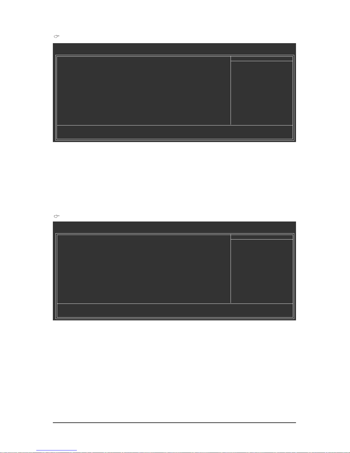
GA-EX58-EXTREME Motherboard - 62 -
Controller 0 (GSATA2 0/1)/ Controller 1 (GSATA2 2/3)
CMOS Setup Utility-Copyright (C) 1984-2008 Award Software
Controller 0 (GSATA2 0/1)
Item Help
Menu Level
Disk/RAID Status [Press Enter]
Smart Backup Config [Press Enter]
: Move Enter: Select +/-/PU/PD: Value F10: Save ESC: Exit F1: General Help
F5: Previous Values F6: Fail-Safe Defaults F7: Optimized Defaults
The Controller 0 (GSATA2 0/1)/Controller 1 (GSATA2 2/3) submenu allows you to check the
information of the hard drive(s) connected to the GSATA2_0~3 connectors or to configure a RAID array.
The Controller 0 (GSATA2 0/1) supports the GSATA2_0 and GSATA2_1 connectors and the Control-
ler 1 (GSATA2 2/3) supports the GSATA2_2 and GSATA2_3 connectors. After the configuration, ensure
the SATA controller driver has been installed in the operating system. You can install the Smart Backup
utility (refer to Chapter 5, "Configuring SATA Hard Drive(s)," to view the device status in the operating
system.
Smart Backup
CMOS Setup Utility-Copyright (C) 1984-2008 Award Software
Smart Backup
Item Help
Menu Level
Controller 0 (GSATA2 0/1) [Press Enter]
Controller 1 (GSATA2 2/3) [Press Enter]
: Move Enter: Select +/-/PU/PD: Value F10: Save ESC: Exit F1: General Help
F5: Previous Values F6: Fail-Safe Defaults F7: Optimized Defaults
Page 63
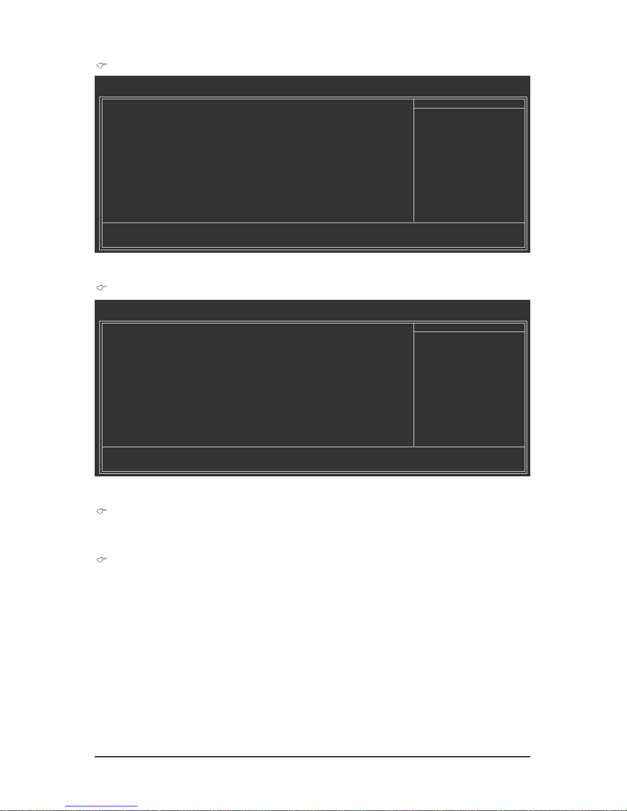
- 63 - BIOS Setup
Smart Backup Config
Allows you to configure your SATA hard drives or to build a RAID array. Options are Performance
(RAID 0), Safe (RAID 1), Big (JBOD), and Normal (Port Multiplier)
(Note)
.
Apply RAID Config
After configuring the Smart Backup Config item above, press <Enter> on this item for the
settings to take effect. When the "Apply RAID Config (Y/N)?" message appears, press <Y> to
confirm. (Note: If you want to erase an existing RAID array and set up a new array, make sure
to set Smart Backup Config to Normal first, and then select the RAID mode you want.)
(Note) When the hard drive(s) is set to Normal mode, make sure to install the SATA controller driver
in the operating system for the hard drive(s) to be properly detected and to support hot plug.
This menu allows you to configure a RAID array.
Smart Backup Config
CMOS Setup Utility-Copyright (C) 1984-2008 Award Software
Smart Backup Config
Item Help
Menu Level
Smart Backup Config [Performance (RAID 0)]
Apply RAID Config [Press Enter]
=== Disk Info ===
[Port] [Model] [Capacity]
Port 0
Port 1
=== RAID Info ===
[Level] [Capacity] [Member]
Performance 0GB
: Move Enter: Select +/-/PU/PD: Value F10: Save ESC: Exit F1: General Help
F5: Previous Values F6: Fail-Safe Defaults F7: Optimized Defaults
Disk/RAID Status
CMOS Setup Utility-Copyright (C) 1984-2008 Award Software
Disk/RAID Status
Item Help
Menu Level
=== Disk Info ===
[Port] [Model] [Capacity]
Port 0
Port 1
=== RAID Info ===
[Volume] [Model] [Capacity] [Status]
: Move Enter: Select +/-/PU/PD: Value F10: Save ESC: Exit F1: General Help
F5: Previous Values F6: Fail-Safe Defaults F7: Optimized Defaults
This menu provides information on the connected hard drive(s) and RAID array.
Page 64
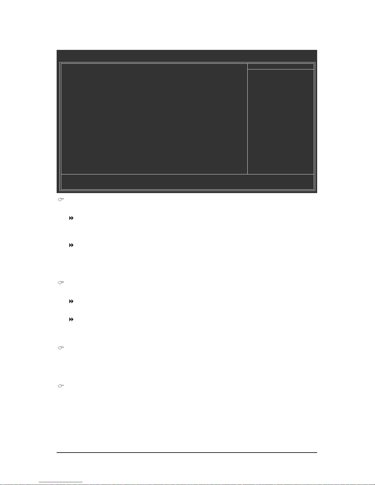
GA-EX58-EXTREME Motherboard - 64 -
2- 7 Power Management Setup
ACPI Suspend Type
Specifies the ACPI sleep state when the system enters suspend.
S1(POS) Enables the system to enter the ACPI S1 (Power on Suspend) sleep state.
In S1 sleep state, the system appears suspended and stays in a low power
mode. The system can be resumed at any time.
S3(STR) Enables the system to enter the ACPI S3 (Suspend to RAM) sleep state
(default). In S3 sleep state, the system appears to be off and consumes less
power than in the S1 state. When signaled by a wake-up device or event,
the system resumes to its working state exactly where it was left off.
Soft-Off by PWR-BTTN
Configures the way to turn off the computer in MS-DOS mode using the power button.
Instant-Off Press the power button and then the system will be turned off instantly.
(Default)
Delay 4 Sec. Press and hold the power button for 4 seconds to turn off the system. If the
power button is pressed for less than 4 seconds, the system will enter
suspend mode.
PME Event Wake Up
Allows the system to be awakened from an ACPI sleep state by a wake-up signal from a PCI or
PCIe device. Note: To use this function, you need an ATX power supply providing at least 1A on
the +5VSB lead. (Default: Enabled)
Power On by Ring
Allows the system to be awakened from an ACPI sleep state by a wake-up signal from a modem
that supports wake-up function. (Default: Enabled)
(Note) Supported on Windows® Vista® operating system only.
CMOS Setup Utility-Copyright (C) 1984-2008 Award Software
Power Management Setup
ACPI Suspend Type [S3(STR)]
Soft-Off by PWR-BTTN [Instant-Off]
PME Event Wake Up [Enabled]
Power On by Ring [Enabled]
Resume by Alarm [Disabled]
x Date(of Month) Alarm Everyday
x Time(hh:mm:ss) Alarm 0 : 0 : 0
HPET Support
(Note)
[Disabled]
x HPET Mode
(Note)
32-bit mode
Power On By Mouse [Disabled]
Power On By Keyboard [Disabled]
x KB Power ON Password Enter
AC Back Function [Soft-Off]
: Move Enter: Select +/-/PU/PD: Value F10: Save ESC: Exit F1: General Help
F5: Previous Values F6: Fail-Safe Defaults F7: Optimized Defaults
Item Help
Menu Level
Page 65
- 65 - BIOS Setup
Resume by Alarm
Determines whether to power on the system at a desired time. (Default: Disabled)
If enabled, set the date and time as following:
Date(of Month) Alarm: Turn on the system at a specific time on each day or on a specific day
in a month.
Time(hh: mm: ss) Alarm: Set the time at which the system will be powered on automatically.
Note: When using this function, avoid inadequate shutdown from the operating system or removal
of the AC power, or the settings may not be effective.
HPET Support
(Note)
Enables or disables High Precision Event Timer (HPET) for Windows® Vista® operating system.
(Default: Disabled)
HPET Mode
(Note)
Allows you to select the HPET mode for your Windows® Vista® operating system. Select 32-bit
mode when you install 32-bit Windows® Vista®; select 64-bit mode when you install 64-bit
Windows® Vista®. (Default: 32-bit mode)
Power On By Mouse
Allows the system to be turned on by a PS/2 mouse wake-up event.
Note: To use this function, you need an ATX power supply providing at least 1A on the +5VSB lead.
Disabled Disables this function. (Default)
Double Click Double click on left button on the PS/2 mouse to turn on the system.
Power On By Keyboard
Allows the system to be turned on by a PS/2 keyboard wake-up event.
Note: you need an ATX power supply providing at least 1A on the +5VSB lead.
Disabled Disables this function. (Default)
Password Set a password with 1~5 characters to turn on the system.
Keyboard 98 Press POWER button on the Windows 98 keyboard to turn on the system.
KB Power ON Password
Set the password when Power On by Keyboard is set to Password. Press <Enter> on this item
and set a password with up to 5 characters and then press <Enter> to accept. To turn on the
system, enter the password and press <Enter>.
Note: To cancel the password, press <Enter> on this item. When prompted for the password, press
<Enter> again without entering the password to clear the password settings.
AC Back Function
Determines the state of the system after the return of power from an AC power loss.
Soft-Off The system stays off upon the return of the AC power. (Default)
Full-On The system is turned on upon the return of the AC power.
Memory The system returns to its last known awake state upon the return of the AC
power.
(Note) Supported on Windows® Vista® operating system only.
Page 66
GA-EX58-EXTREME Motherboard - 66 -
2- 8 PC Health Status
Reset Case Open Status
Keeps or clears the record of previous chassis intrusion status. Enabled clears the record of
previous chassis intrusion status and the Case Opened field will show "No" at next boot. (Default:
Disabled)
Case Opened
Displays the detection status of the chassis intrusion detection device attached to the motherboard
CI header. If the system chassis cover is removed, this field will show "Yes", otherwise it will
show "No". To clear the chassis intrusion status record, set Reset Case Open Status to Enabled,
save the settings to CMOS, and then restart your system.
Current V oltage(V) Vcore/DDR15V/+5V
Displays the current system voltages.
Current System/CPU/MCH T emperature
Displays current system/CPU/North Bridge temperature.
Current CPU/SYSTEM/POWER FAN Speed (RPM)
Displays current CPU/system/power fan speed.
CPU Warning Temperature
Sets the warning threshold for CPU temperature. When CPU temperature exceeds the threshold,
BIOS will emit warning sound. Options are: Disabled (default), 60oC/140oF, 70oC/158oF, 80oC/
176oF, 90oC/194oF.
CPU/SYSTEM/POWER FAN Fail Warning
Allows the system to emit warning sound if the CPU/system/power fan is not connected or fails.
Check the fan condition or fan connection when this occurs. (Default: Disabled)
CMOS Setup Utility-Copyright (C) 1984-2008 Award Software
PC Health Status
Reset Case Open Status [Disabled]
Case Opened No
Vcore 1.220V
DDR15V 1.504V
+5V 4.972V
Current System Temperature 30oC
Current CPU Temperature 47oC
Current MCH Temperature 42oC
Current CPU FAN Speed 3375 RPM
Current SYSTEM FAN2 Speed 0 RPM
Current POWER FAN Speed 0 RPM
Current SYSTEM FAN1 Speed 0 RPM
CPU Warning Temperature [Disabled]
CPU FAN Fail Warning [Disabled]
SYSTEM FAN2 Fail Warning [Disabled]
POWER FAN Fail Warning [Disabled]
SYSTEM FAN1 Fail Warning [Disabled]
CPU Smart FAN Control [Enabled]
CPU Smart FAN Mode [Auto]
: Move Enter: Select +/-/PU/PD: Value F10: Save ESC: Exit F1: General Help
F5: Previous Values F6: Fail-Safe Defaults F7: Optimized Defaults
Item Help
Menu Level
Page 67
- 67 - BIOS Setup
CPU Smart FAN Control
Enables or disables the CPU fan speed control function. Enabled allows the CPU fan to run at
different speed according to the CPU temperature. You can adjust the fan speed with EasyTune
based on system requirements. If disabled, CPU fan runs at full speed. (Default: Enabled)
CPU Smart FAN Mode
Specifies how to control CPU fan speed. This item is configurable only if CPU Smart FAN
Control is set to Enabled.
Auto Lets BIOS autodetect the type of CPU fan installed and sets the optimal CPU
fan control mode. (Default)
Voltage Sets Voltage mode for a 3-pin CPU fan.
PWM Sets PWM mode for a 4-pin CPU fan.
Note: The Voltage mode can be set for a 3-pin CPU fan or a 4-pin CPU fan. However, for a 4-pin
CPU fan that is not designed following Intel PWM fan specifications, selecting PWM mode may not
effectively reduce the fan speed.
Page 68
GA-EX58-EXTREME Motherboard - 68 -
2- 9 Load Fail-Safe Defaults
Press <Enter> on this item and then press the <Y> key to load the safest BIOS default settings.
In case system instability occurs, you may try to load Fail-Safe defaults, which are the safest and most
stable BIOS settings for the motherboard.
2-10 Load Optimized Defaults
Press <Enter> on this item and then press the <Y> key to load the optimal BIOS default settings. The
BIOS defaults settings helps the system to operate in optimum state. Always load the Optimized defaults
after updating the BIOS or after clearing the CMOS values.
CMOS Setup Utility-Copyright (C) 1984-2008 Award Software
MB Intelligent Tweaker(M.I.T.)
Standard CMOS Features
Advanced BIOS Features
Integrated Peripherals
Power Management Setup
PC Health Status
ESC: Quit : Select Item F11: Save CMOS to BIOS
F8: Q-Flash F10: Save & Exit Setup F12: Load CMOS from BIOS
Load Fail-Safe Defaults
Load Fail-Safe Defaults
Load Optimized Defaults
Set Supervisor Password
Set User Password
Save & Exit Setup
Exit Without Saving
Load Fail-Safe Defaults (Y/N)? N
CMOS Setup Utility-Copyright (C) 1984-2008 Award Software
MB Intelligent Tweaker(M.I.T.)
Standard CMOS Features
Advanced BIOS Features
Integrated Peripherals
Power Management Setup
PC Health Status
ESC: Quit : Select Item F11: Save CMOS to BIOS
F8: Q-Flash F10: Save & Exit Setup F12: Load CMOS from BIOS
Load Optimized Defaults
Load Fail-Safe Defaults
Load Optimized Defaults
Set Supervisor Password
Set User Password
Save & Exit Setup
Exit Without Saving
Load Optimized Defaults (Y/N)? N
Page 69
- 69 - BIOS Setup
2- 11 Set Supervisor/User Password
Press <Enter> on this item and type the password with up to 8 characters and then press <Enter>. You
will be requested to confirm the password. Type the password again and press <Enter>.
The BIOS Setup program allows you to specify two separate passwords:
Supervisor Password
When a system password is set and the Password Check item in Advanced BIOS Features is
set to Setup, you must enter the supervisor password for entering BIOS Setup and making BIOS
changes.
When the Password Check item is set to System, you must enter the supervisor password (or
user password) at system startup and when entering BIOS Setup.
User Password
When the Password Check item is set to System, you must enter the supervisor password (or
user password) at system startup to continue system boot. In BIOS Setup, you must enter the
supervisor password if you wish to make changes to BIOS settings. The user password only
allows you to view the BIOS settings but not to make changes.
To clear the password, press <Enter> on the password item and when requested for the password,
press <Enter> again. The message "PASSWORD DISABLED" will appear, indicating the password has
been cancelled.
CMOS Setup Utility-Copyright (C) 1984-2008 Award Software
MB Intelligent Tweaker(M.I.T.)
Standard CMOS Features
Advanced BIOS Features
Integrated Peripherals
Power Management Setup
PC Health Status
ESC: Quit : Select Item F11: Save CMOS to BIOS
F8: Q-Flash F10: Save & Exit Setup F12: Load CMOS from BIOS
Change/Set/Disable Password
Load Fail-Safe Defaults
Load Optimized Defaults
Set Supervisor Password
Set User Password
Save & Exit Setup
Exit Without Saving
Enter Password:
Page 70
GA-EX58-EXTREME Motherboard - 70 -
2-12 Save & Exit Setup
2-13 Exit Without Saving
Press <Enter> on this item and press the <Y> key. This saves the changes to the CMOS and exits the
BIOS Setup program. Press <N> or <Esc> to return to the BIOS Setup Main Menu.
Press <Enter> on this item and press the <Y> key. This exits the BIOS Setup without saving the
changes made in BIOS Setup to the CMOS. Press <N> or <Esc> to return to the BIOS Setup Main Menu.
CMOS Setup Utility-Copyright (C) 1984-2008 Award Software
MB Intelligent Tweaker(M.I.T.)
Standard CMOS Features
Advanced BIOS Features
Integrated Peripherals
Power Management Setup
PC Health Status
ESC: Quit : Select Item F11: Save CMOS to BIOS
F8: Q-Flash F10: Save & Exit Setup F12: Load CMOS from BIOS
Save Data to CMOS
Load Fail-Safe Defaults
Load Optimized Defaults
Set Supervisor Password
Set User Password
Save & Exit Setup
Exit Without Saving
Save to CMOS and EXIT (Y/N)? Y
CMOS Setup Utility-Copyright (C) 1984-2008 Award Software
MB Intelligent Tweaker(M.I.T.)
Standard CMOS Features
Advanced BIOS Features
Integrated Peripherals
Power Management Setup
PC Health Status
ESC: Quit : Select Item F11: Save CMOS to BIOS
F8: Q-Flash F10: Save & Exit Setup F12: Load CMOS from BIOS
Abandon all Data
Load Fail-Safe Defaults
Load Optimized Defaults
Set Supervisor Password
Set User Password
Save & Exit Setup
Exit Without Saving
Quit Without Saving (Y/N)? N
Page 71
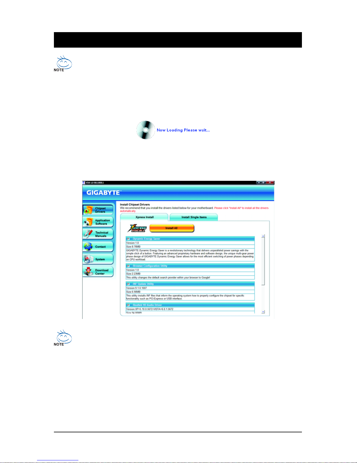
Drivers Installation- 71 -
Chapter 3 Drivers Installation
3- 1 Installing Chipset Drivers
• Before installing the drivers, first install the operating system.
• After installing the operating system, insert the motherboard driver disk into your optical drive.
The driver Autorun screen is automatically displayed which looks like that shown in the screen
shot below. (If the driver Autorun screen does not appear automatically, go to My Computer,
double-click the optical drive and execute the Run.exe program.)
After inserting the driver disk, "Xpress Install" will automatically scan your system and then list all the
drivers that are recommended to install. You can click the Install All button and "Xpress Install" will
install all the recommended drivers. Or click Install Single Items to manually select the drivers you
wish to install.
• Please ignore the popup dialog box(es) (e.g. the Found New Hardware Wizard) displayed
when "Xpress Install" is installing the drivers. Failure to do so may affect the driver installation.
• Some device drivers will restart your system automatically during the driver installation.
After the system restart, "Xpress Install" will continue to install other drivers.
• After the drivers are installed, follow the onscreen instructions to restart your system. You
can install other applications included in the motherboard driver disk.
• For USB 2.0 driver support under the Windows XP operating system, please install the
Windows XP Service Pack 1 or later. After installing the SP1 (or later), if a question mark still
exists in Universal Serial Bus Controller in Device Manager, please remove the
question mark (by right-clicking your mouse and select Uninstall) and restart the system.
(The system will then autodetect and install the USB 2.0 driver.)
Page 72
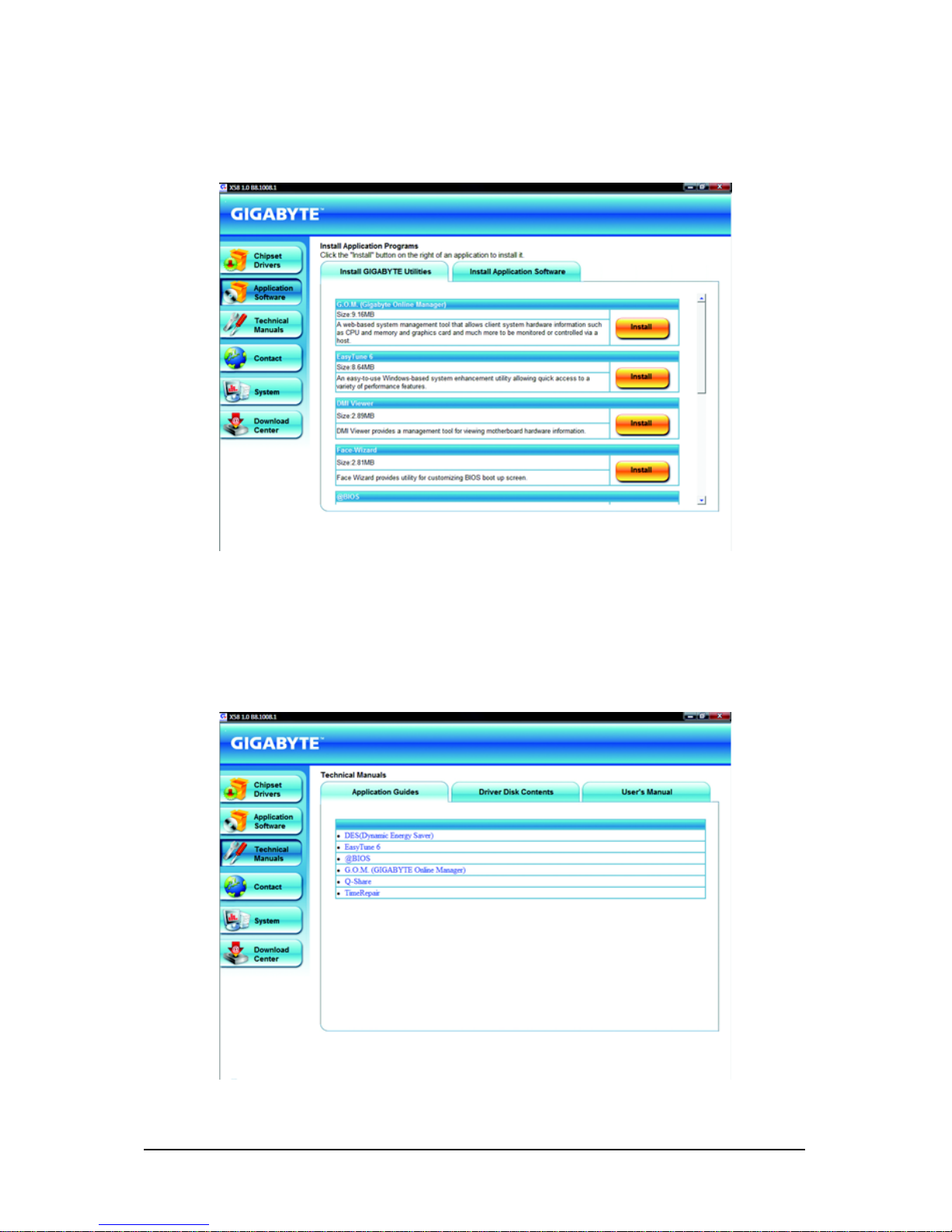
GA-EX58-EXTREME Motherboard - 72 -
3- 2 Application Software
This page displays all the utilities and applications that GIGABYTE develops and some free software.
You can click the Install button on the right of an item to install it.
3- 3 Technical Manuals
This page provides GIGABYTE's application guides, content descriptions for this driver disk, and the
motherboard manuals.
Page 73
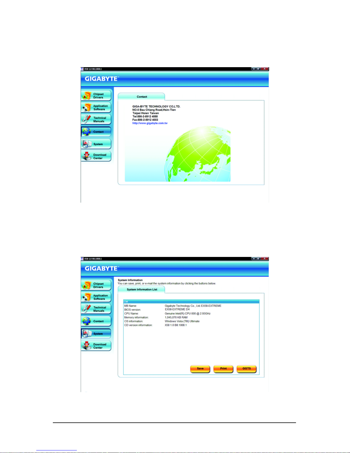
Drivers Installation- 73 -
3-4 Contact
Click the URL on this page to link to the GIGABYTE Web site. Or read the last page of this manual to check
the contact information for GIGABYTE Taiwan headquarter or worldwide branch offices.
3-5 System
This page provides the basic system information.
Page 74
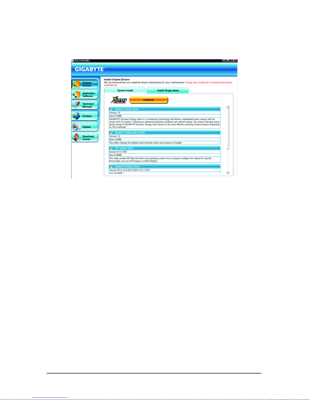
GA-EX58-EXTREME Motherboard - 74 -
3-6 Download Center
To update the BIOS, drivers, or applications, click the Download Center button to link to the GIGABYTE
Web site. The latest version of the BIOS, drivers, or applications will be displayed.
Page 75
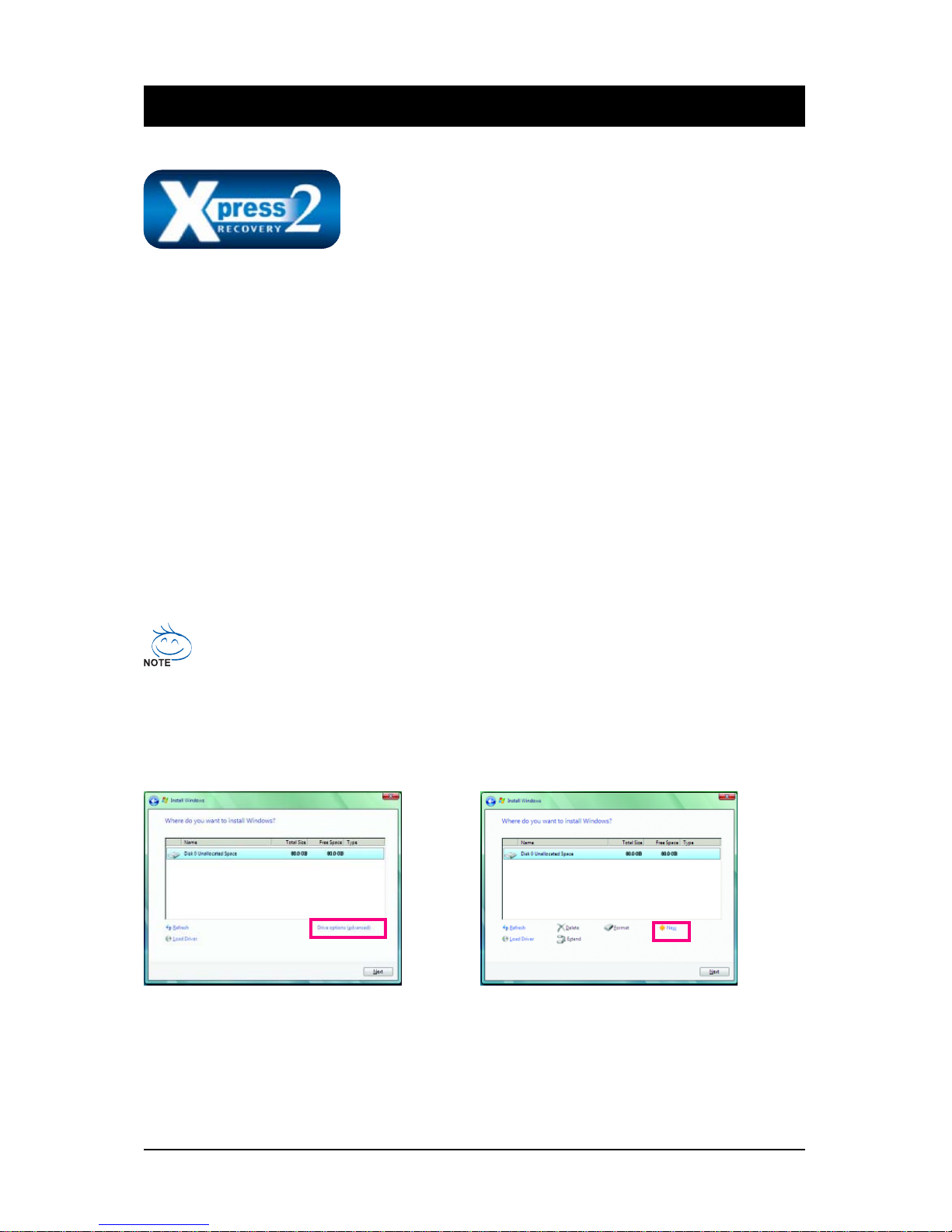
Unique Features- 75 -
Chapter 4 Unique Features
4-1 Xpress Recovery2
"*" Xpress Recovery2 checks the first physical hard drive in the following sequence: The first P ATA IDE connector,
the second PATA IDE connector, the first SATA connector, the second SATA connector and so forth. For
example, when hard drives are attached to the first IDE and the first SATA connectors, the hard drive on the first
IDE connector is the first physical drive. When hard drives are attached to the first and second SATA connectors,
the hard drive on the first SATA connector is the first physical drive.
Xpress Recovery2 is a utility that allows you to quickly compress and
back up your system data and perform restoration of it. Supporting
NTFS, FAT32, and FAT16 file systems, Xpress Recovery2 can back
up data on PATA and SATA hard drives and restore it.
Before Y ou Begin:
• Xpress Recovery2 will check the first physical hard drive* for the operating system. Xpress
Recovery2 can only back up/restore the first physical hard drive that has the operating system
installed.
• As Xpress Recovery2 will save the backup file at the end of the hard drive, make sure to leave
enough unallocated space in advanced (10 GB or more is recommended; actual size requirements vary, depending on the amount of data).
• It is recommended to back up your system soon after the operating system and drivers are
installed.
• The amount of data and hard drive access speed may affect the speed at which the data is backed
up/restored.
• It takes longer to back up a hard drive than to restore it.
System Requirements:
• Intel® platform
• At least 512 MB of system memory
• VESA compatible graphics card
• Windows® XP with SP1 or later, Windows® Vista
• Xpress Recovery and Xpress Recovery2 are different utilities. For example, a backup file created with Xpress
Recovery cannot be restored using Xpress Recovery2.
• USB hard drives are not supported.
• Hard drives in RAID/AHCI mode are not supported.
Installation and Configuration
Turn on your system to boot from the Windows Vista setup disk.
A. Installing Windows Vista and Partitioning the Hard Drive
Step 1:
Click Drive options.
Step 2:
Click New.
Page 76
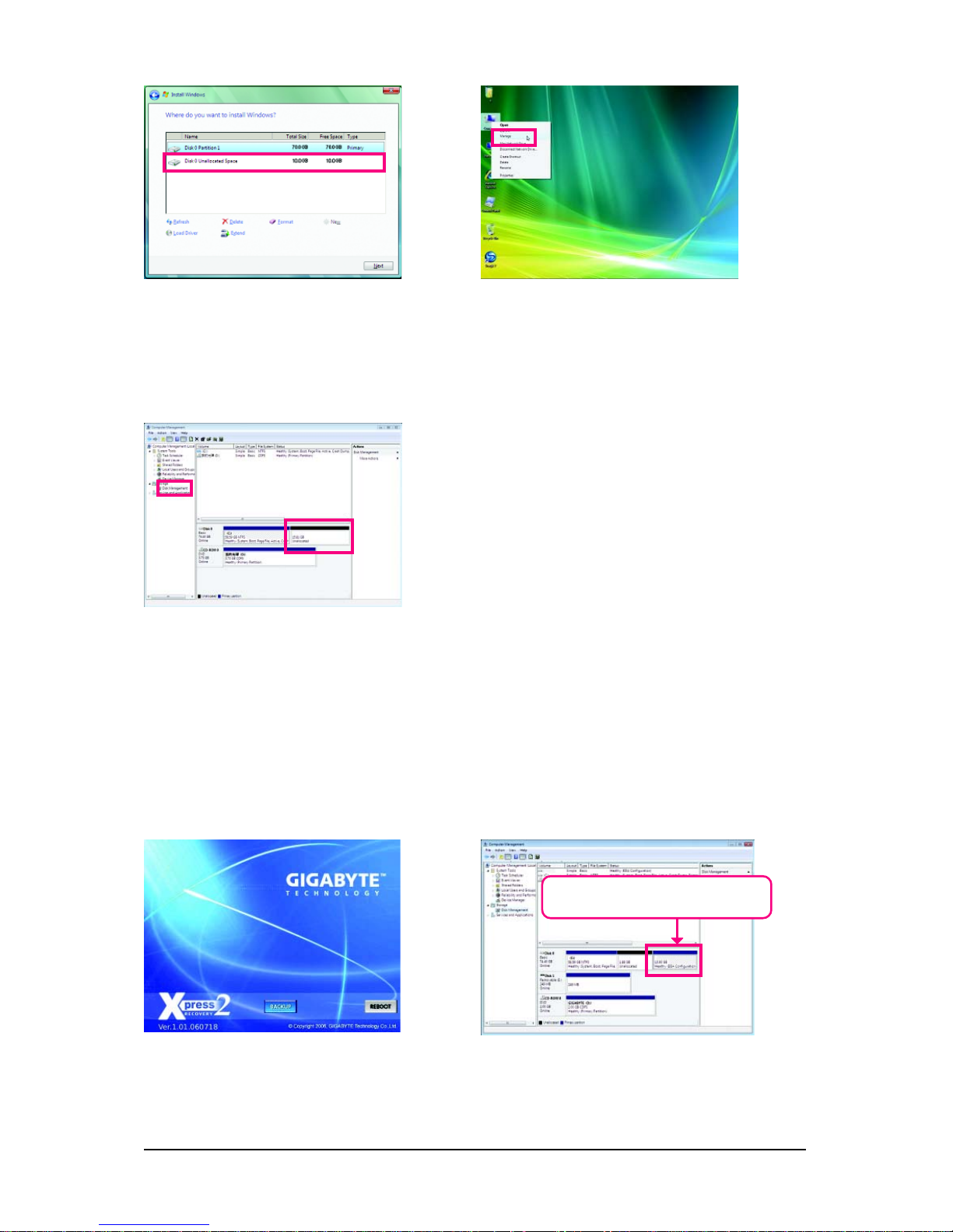
GA-EX58-EXTREME Motherboard - 76 -
Step 3:
When partitioning your hard drive, make sure
to leave unallocated space (10 GB or more is
recommended; actual size requirements vary,
depending on the amount of data) and begin the
installation of the operating system.
Step 4:
After the operating system is installed, rightclick the Computer icon on your desktop
and select Manage. Go to Disk Management
to check disk allocation.
Step 5:
Xpress Recovery2 will save the backup file to the
unallocated space (black stripe along the top). Please
note that if there is no enough unallocated space, Xpress
Recovery2 cannot save the backup file.
B. Accessing Xpress Recovery2
1. Boot from the motherboard driver disk to access Xpress Recovery2 for the first time. When you see
the following message: Press any key to startup Xpress Recovery2 , press
any key to enter Xpress Recovery2.
2. After you use the backup function in Xpress Recovery2 for the first time, Xpress Recovery2 will stay
permanent in your hard drive. If you wish to enter Xpress Recovery2 later, simply press <F9> during
the POST.
C. Using the Backup Function in Xpress Recovery2
Step 1:
Select BACKUP to start backing up your hard
drive data.
Step 2:
When finished, go to Disk Management to
check disk allocation.
Xpress Recovery2 will automatically create a
new partition to store the backup image file.
Page 77
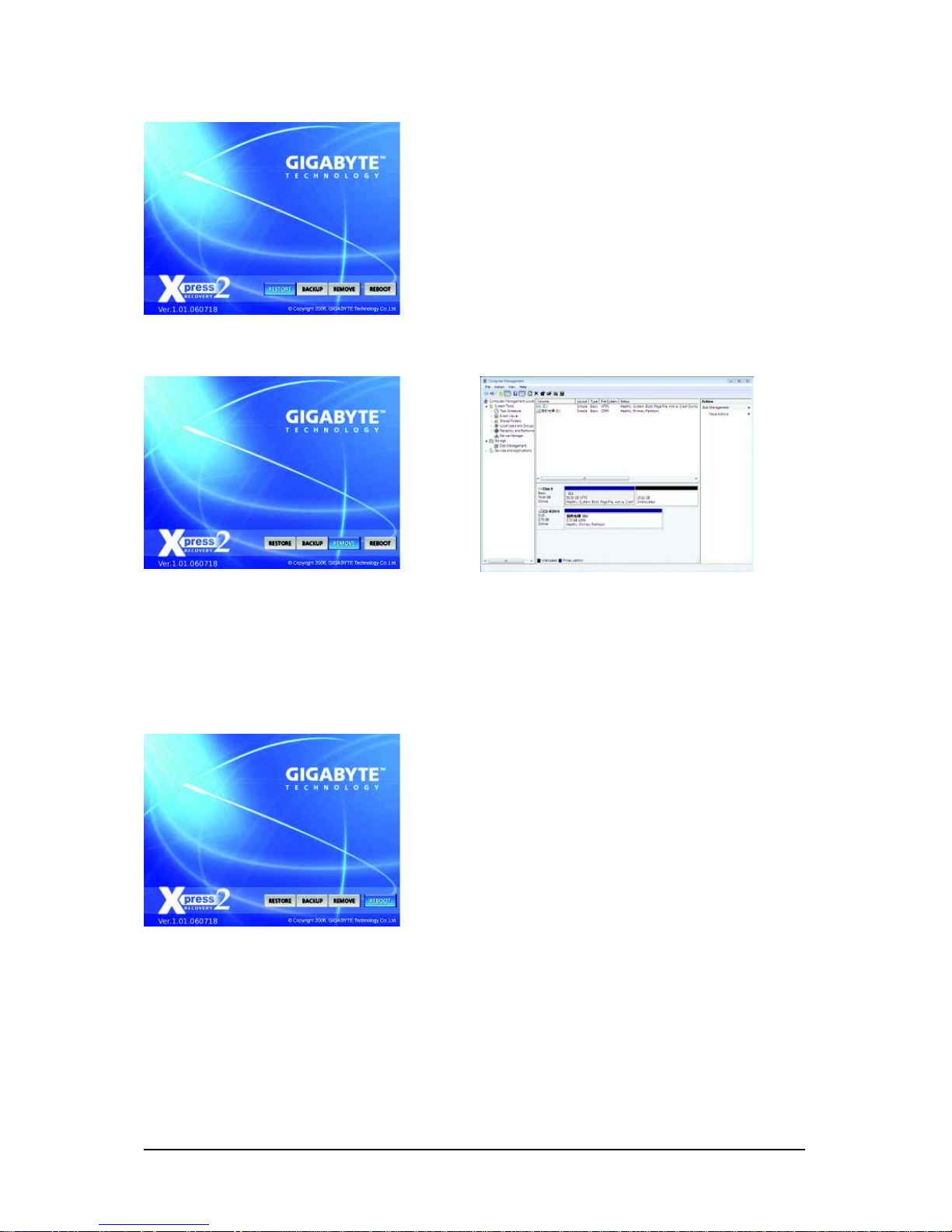
Unique Features- 77 -
E. Removing the Backup
D. Using the Restore Function in Xpress Recovery2
F. Exiting Xpress Recovery2
Select REBOOT to exit Xpress Recovery2.
Select RESTORE to restore the backup to your hard
drive in case the system breaks down. The RESTORE
option will not be present if no backup is created before.
Step 1:
If you wish to remove the backup file, select
REMOVE.
Step 2:
After the backup file is removed, no backup
image file will be present in Disk Management
and hard drive space will be freed up.
Page 78
GA-EX58-EXTREME Motherboard - 78 -
4-2-1 Updating the BIOS with the Q-Flash Utility
A. Before You Begin:
1. From GIGABYTE's website, download the latest compressed BIOS update file that matches your
motherboard model.
2. Extract the file and save the new BIOS file (e.g. ex58ex.f1) to your floppy disk, USB flash drive,
or hard drive. Note: The USB flash drive or hard drive must use FAT32/16/12 file system.
3. Restart the system. During the POST, press the <End> key to enter Q-Flash. Note: You can
access Q-Flash by either pressing the <End> key during the POST or pressing the <F8> key in
BIOS Setup. However, if the BIOS update file is saved to a hard drive in RAID/AHCI mode or a hard
drive attached to an independent IDE/SATA controller, use the <End> key during the POST to
access Q-Flash.
Because BIOS flashing is potentially risky, please do it with caution. Inadequate BIOS
flashing may result in system malfunction.
4- 2 BIOS Update Utilities
GIGABYTE motherboards provide two unique BIOS update tools, Q-FlashTM and @BIOSTM. GIGABYTE
Q-Flash and @BIOS are easy-to-use and allow you to update the BIOS without the need to enter MSDOS mode. Additionally, this motherboard features the DualBIOSTM design, which enhances protection
for the safety and stability of your computer by adding one more physical BIOS chip.
What is DualBIOSTM?
Motherboards that support DualBIOS have two BIOS onboard, a main BIOS
and a backup BIOS. Normally, the system works on the main BIOS.
However, if the main BIOS is corrupted or damaged, the backup BIOS will take over on the next system
boot and copy the BIOS file to the main BIOS to ensure normal system operation. For the sake of
system safety, users cannot update the backup BIOS manually.
What is Q-FlashTM?
With Q-Flash you can update the system BIOS without having to enter
operating systems like MS-DOS or Window first. Embedded in the BIOS, the
Q-Flash tool frees you from the hassles of going through complicated BIOS flashing process.
What is @BIOSTM?
@BIOS allows you to update the system BIOS while in the Windows
environment. @BIOS will download the latest BIOS file from the nearest
@BIOS server site and update the BIOS.
Award Modular BIOS v6.00PG, An Energy Star Ally
Copyright (C) 1984-2008, Award Software, Inc.
EX58-EXTREME D22
.
.
.
.
<DEL>: BIOS Setup <F9>: XpressRecovery2 <F12>: Boot Menu <End>: Qflash
10/15/2008-X58-ICH10-7A89QG02C-00
Page 79
Unique Features- 79 -
B. Updating the BIOS
When updating the BIOS, choose the location where the BIOS file is saved. The follow procedure
assumes that you save the BIOS file to a floppy disk.
Step 1:
1. Insert the floppy disk containing the BIOS file into the floppy disk drive. In the main menu of
Q-Flash, use the up or down arrow key to select Update BIOS from Drive and press <Enter>.
• The Save Main BIOS to Drive option allows you to save the current BIOS file.
• Q-Flash only supports USB flash drive or hard drives using FAT32/16/12 file system.
• If the BIOS update file is saved to a hard drive in RAID/AHCI mode or a hard drive
attached to an independent IDE/SATA controller, use the <End> key during the POST to
access Q-Flash.
2. Select Floppy A and press <Enter>.
Q-Flash Utility v2.05
Flash Type/Size.................................MXIC 25L8005 1M
Keep DMI Data Enable
Update BIOS from Drive
Save BIOS to Drive
Enter : Run :Move ESC:Reset F10:Power Off
0 file(s) found
Floppy A <Drive>
HDD 0-0 <Drive>
Total size : 0 Free size : 0
3. Select the BIOS update file and press <Enter>.
Make sure the BIOS update file matches your motherboard model.
Step 2:
The process of the system reading the BIOS file from the floppy disk is displayed on the screen. When
the message "Are you sure to update BIOS?" appears, press <Enter> to begin the BIOS update. The
monitor will display the update process.
• Do not turn off or restart the system when the system is reading/updating the BIOS.
• Do not remove the floppy disk, USB flash drive, or hard drive when the system is
updating the BIOS.
Step 3:
When the update process is complete, press any key to return to the main menu.
Q-Flash Utility v2.05
Flash Type/Size.................................MXIC 25L8005 1M
Keep DMI Data Enable
Update BIOS from Drive
Save BIOS to Drive
Enter : Run :Move ESC:Reset F10:Power Off
!! Copy BIOS completed - Pass !!
Please press any key to continue
Page 80
GA-EX58-EXTREME Motherboard - 80 -
Step 6:
Select Save & Exit Setup and then press <Y> to save settings to CMOS and exit BIOS Setup. The
procedure is complete after the system restarts.
Press <Y> to load BIOS defaults
Step 4:
Press <Esc> and then <Enter> to exit Q-Flash and reboot the system. As the system boots, you should
see the new BIOS version is present on the POST screen.
Step 5:
During the POST, press <Delete> to enter BIOS Setup. Select Load Optimized Defaults and press
<Enter> to load BIOS defaults. System will re-detect all peripherals devices after a BIOS update, so we
recommend that you reload BIOS defaults.
CMOS Setup Utility-Copyright (C) 1984-2008 Award Software
MB Intelligent Tweaker(M.I.T.)
Standard CMOS Features
Advanced BIOS Features
Integrated Peripherals
Power Management Setup
PC Health Status
ESC: Quit : Select Item F11: Save CMOS to BIOS
F8: Q-Flash F10: Save & Exit Setup F12: Load CMOS from BIOS
Load Optimized Defaults
Load Fail-Safe Defaults
Load Optimized Defaults
Set Supervisor Password
Set User Password
Save & Exit Setup
Exit Without Saving
Load Optimized Defaults (Y/N)? N
Page 81
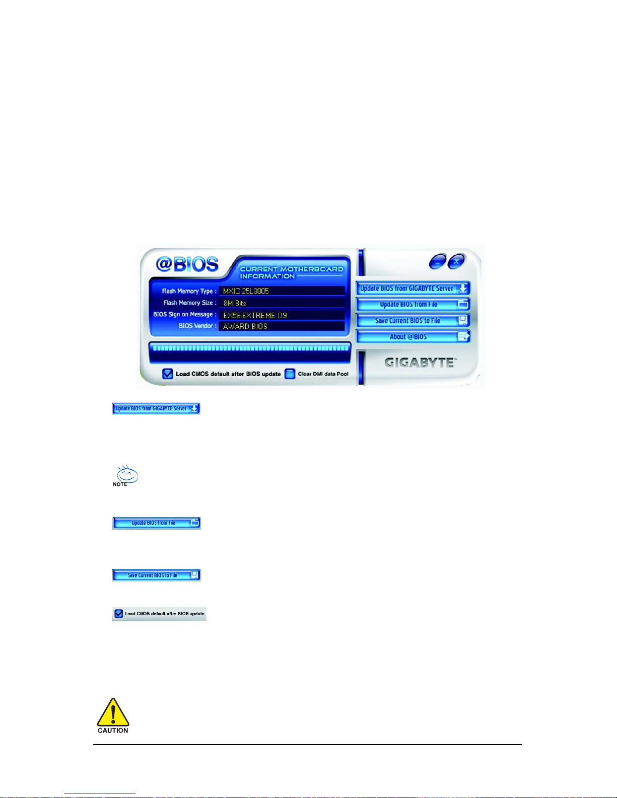
Unique Features- 81 -
4-2-2 Updating the BIOS with the @BIOS Utility
A. Before You Begin:
1. In Windows, close all applications and TSR (Terminate and Stay Resident) programs. This helps
prevent unexpected failures when performing a BIOS update.
2. During the BIOS update process, ensure the Internet connection is stable and do NOT interrupt the
Internet connection (for example, avoid a power loss or switching off the Internet). Failure to do so
may result in a corrupted BIOS or a system that is unable to start.
3. Do not use the G.O.M. (GIGABYTE Online Management) function when using @BIOS.
4. GIGABYTE product warranty does not cover any BIOS damage or system failure resulting from an
inadequate BIOS flashing.
B. Using @BIOS:
If the BIOS update file for your motherboard is not present on the @BIOS server site, please
manually download the BIOS update file from GIGABYTE's website and follow the instructions in "Update the BIOS without Using the Internet Update Function" below.
2. Update the BIOS without Using the Internet Update Function:
Click Update BIOS from File, then select the location where you save the BIOS update file
obtained from the Internet or through other source. Follow the on-screen instructions to complete.
1. Update the BIOS Using the Internet Update Function:
Click Update BIOS from GIGABYTE Server, select the @BIOS server site closest to your
location and then download the BIOS file that matches your motherboard model. Follow the onscreen instructions to complete.
3. Save Current BIOS to File:
Click Save Current BIOS to save the current BIOS file.
C. After Updating the BIOS:
Restart your system after updating the BIOS.
Make sure that the BIOS file to be flashed matches your motherboard model. Updating the
BIOS with an incorrect BIOS file could cause your system not to boot.
4. Load BIOS defaults after BIOS Update:
Select the Load CMOS default after BIOS update check box and then the system will automatically
load BIOS defaults after BIOS update and after the system restarts.
Page 82
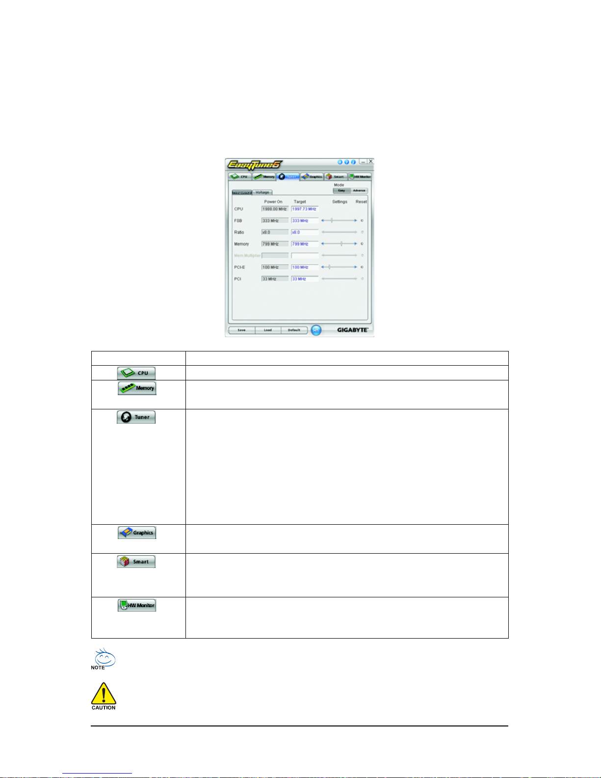
GA-EX58-EXTREME Motherboard - 82 -
4- 3 EasyTune 6
GIGABYTE's EasyTune 6 is a simple and easy-to-use interface that allows users to fine-tune their
system settings or do overclock/overvoltage in Windows environment. The user-friendly EasyTune 6
interface also includes tabbed pages for CPU and memory information, lettings users read their systemrelated information without the need to install additional software.
The EasyTune 6 Interface
Tabs Information
Tab Function
The CPU tab provides information on the installed CPU and motherboard.
The Memory tab provides information on the installed memory module(s).
You can select memory module on a specific slot to see its information.
The Tuner tab allows you to change system clock settings and voltages.
• Easy mode allows you to adjust the CPU FSB only.
• Advanced mode allows you to individually change system clock
settings and voltages settings using the sliders.
• Save allows you to save the current settings to a new profile (.txt file).
• Load allows you to load previous settings from a profile.
After making changes, be sure to click Set for these changes to take effect
or click Default to restore to default values.
The Graphics tab allows you to change the core clock and memory clock
for your ATI or NVIDIA graphics card.
The Smart tab allows you to specify a C.I.A.2 level and a Smart Fan mode.
Smart Fan Advance Mode allows the CPU fan speed to be changed
linearly based on the CPU temperature thresholds you set.
The HW Monitor tab allows you to monitor hardware temperature, voltage and fan speed and set temperature/fan speed alarm. You can choose
the alert sound from the buzzer or use your own sound file (.wav file).
Available functions in EasyTune 6 may differ by motherboard model. Grayed-out area(s) indicates that the item is not
configurable or the function is not supported.
Incorrectly doing overclock/overvoltage may result in damage to the hardware components such as CPU, chipset, and
memory and reduce the useful life of these components. Before you do the overclock/overvoltage, make sure that you
fully know each function of EasyTune 6, or system instability or other unexpected results may occur.
Page 83
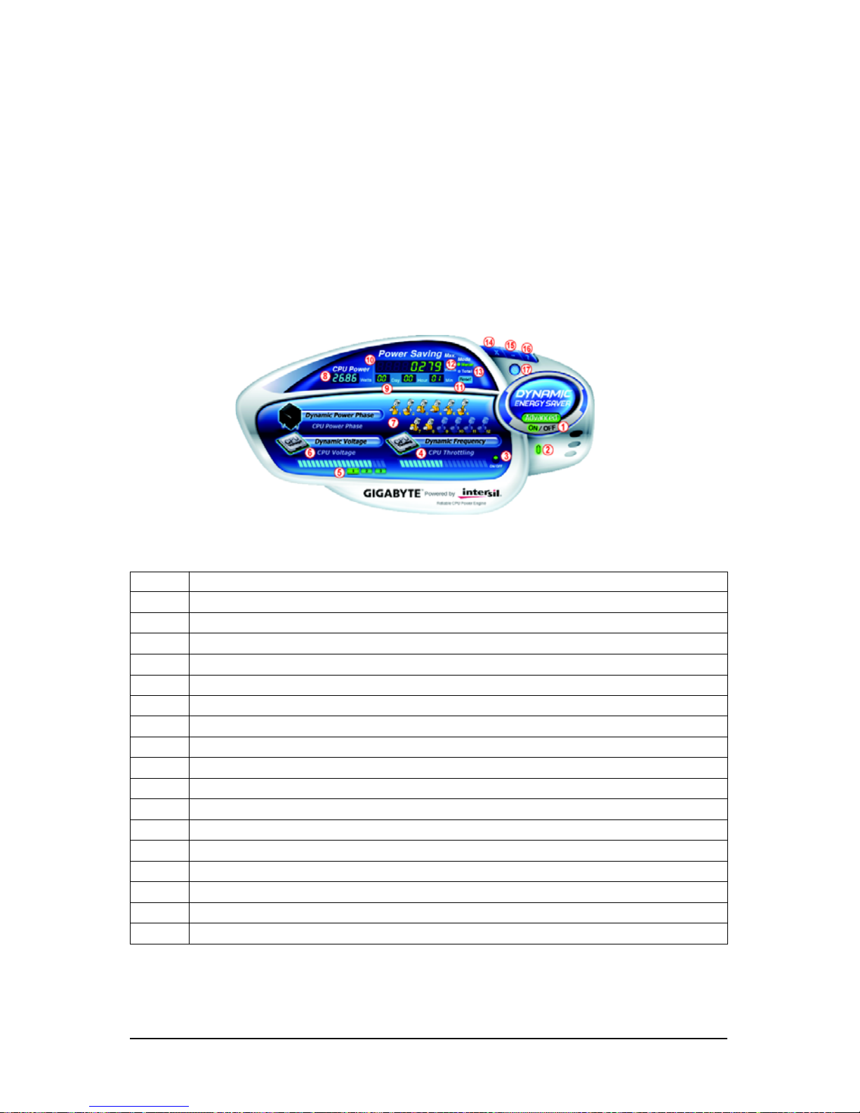
Unique Features- 83 -
4- 4 Dynamic Energy Saver Advanced
GIGABYTE Dynamic Energy Saver Advanced
(Note 1)
is a revolutionary technology that delivers unparalleled power savings with a click of the button. Featuring an advanced proprietary hardware and
software design, GIGABYTE Dynamic Energy Saver Advanced is able to provide exceptional power
savings and enhanced power efficiency without sacrificing computing performance.
The Dynamic Energy Saver Advanced Interface
A. Meter Mode
In Meter Mode, GIGABYTE Dynamic Energy Saver Advanced shows how much power they have
saved in a set period of time.
Meter Mode - Button Information T able
Button Description
1 Dynamic Energy Saver On/Off Switch (Default: Off)
2 Motherboard Phase LED On/Off Switch (Default: On)
3 Dynamic CPU Frequency Function On/Off Switch (Default: Off)
(Note 2)
4 CPU Throttling Display
5 3-Level CPU Voltage Switch (Default:1)
(Note 3)
6 CPU Voltage Display
7 Dynamic Power Phase Status
8 Current CPU Power Consumption
9 Meter Time
10 Power Saving (Calculate power savings based on time)
11 Meter/Timer Reset Switch
12 Meter Mode Switch
13 Total Mode Switch
14 Close (Application will enter Stealth Mode)
15 Minimize (Application will continue to run in taskbar)
16 INFO/Help
17 Live Utility Update (Check for the latest utility version)
• The above data is for reference only. Actual performance may vary depending on motherboard model.
• CPU Power and Power Scores are for reference only. Actual results may vary based on testing method.
Page 84
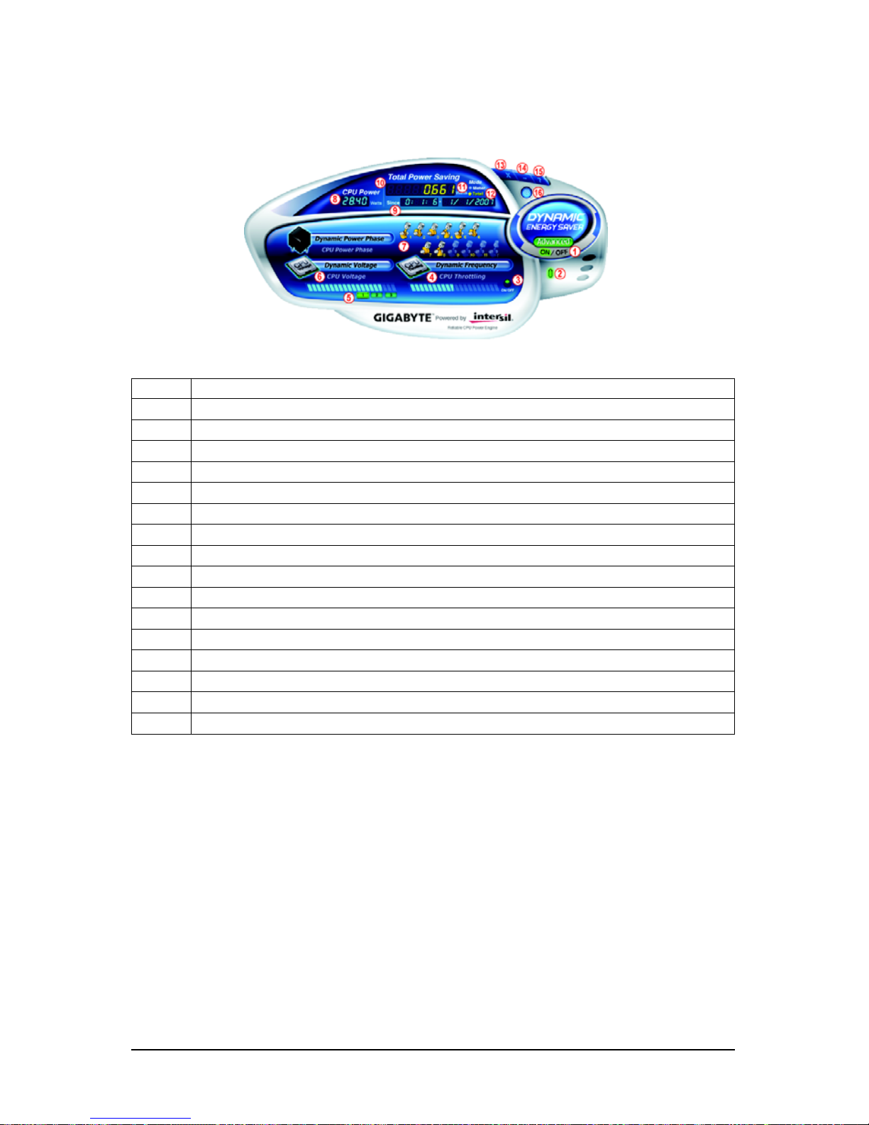
GA-EX58-EXTREME Motherboard - 84 -
Total Mode - Button Information Table
B. Total Mode
In Total Mode, users are able to see how much total power savings they have accumulated in a set
period of time since activating Dynamic Energy Saver Advanced for the first time
(Note 4)
.
(Note 1) Before using the DES function, make sure the CPU Enhanced Halt (C1E) and CPU EIST
Function items in the BIOS Setup program are set to Enabled.
(Note 2) Maximize system power saving with Dynamic Frequency Function; system performance
may be affected.
(Note 3) 1: Normal Power Saving (default); 2: Advanced Power Saving; 3: Extreme Power Saving.
(Note 4) The total amount of power saved will be recorded until re-activated when only the Dynamic
Power Saver is under the enable status, and power savings meter is unable to reset to zero.
(Note 5) Dynamic Energy Saver Meter will automatically reset when the total power saving reaches
99999999 Watts.
Button Description
1 Dynamic Energy Saver On/Off Switch (Default: Off)
2 Motherboard Phase LED On/Off Switch (Default: On)
3 Dynamic CPU Frequency Function On/Off Switch (Default: Off)
4 CPU Throttling Display
5 3-Level CPU Voltage Switch (Default:1)
(Note 3)
6 CPU Voltage Display
7 Dynamic Power Phase Status
8 Current CPU Power Consumption
9 Time/Date Dynamic Energy Saver Enabled
10 Total Power Savings (Total power saving with Dynamic Energy Saver enabled)
(Note 5)
11 Dynamic Energy Saver Meter Mode Switch
12 Dynamic Energy Saver Total Mode Switch
13 Close (Application will enter Stealth Mode)
14 Minimize (Application will continue to run in taskbar)
15 INFO/Help
16 Live Utility Update (Check for the latest utility version)
C. Stealth Mode
In Stealth Mode, the system continues to work with the user-defined power saving settings, even after
the system is restarted. Re-enter the application only if you want to make any changes or completely
close the application.
Page 85
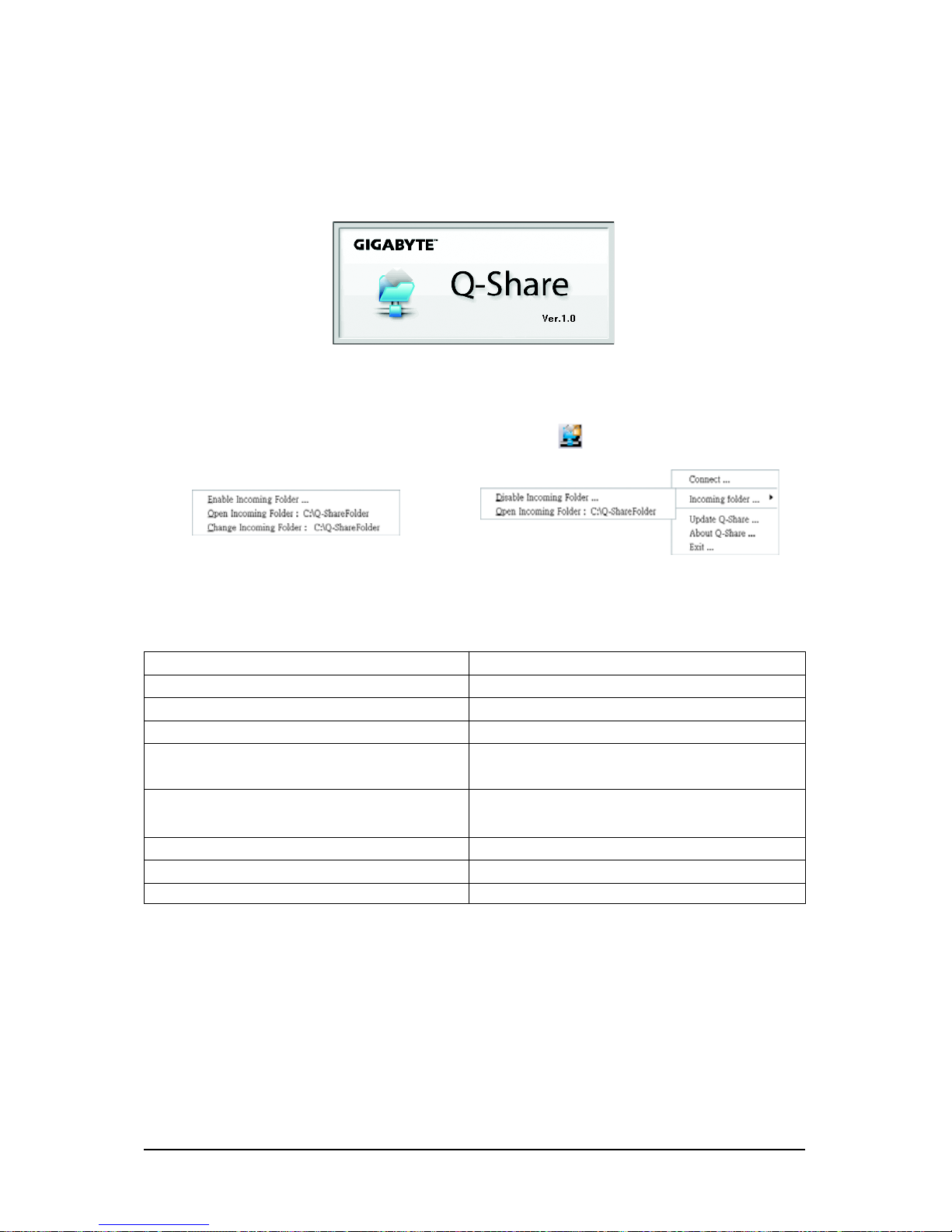
Unique Features- 85 -
4-5 Q-Share
Q-Share is an easy and convenient data sharing tool. After configuring your LAN connection settings
and Q-Share, you are able to share your data with computers on the same network, making full use of
Internet resources.
Directions for using Q-Share
After installing Q-Share from the motherboard driver disk, go to Start>All Programs>GIGABYTE>
Q-Share.exe to launch the Q-Share tool. Find the Q-Share icon in your system tray and right-click
on this icon to configure the data sharing settings.
Figure 2. Data Sharing EnabledFigure 1. Data Sharing Disabled
Options Descriptions
(Note) This option is available only when data sharing is NOT enabled.
Option Description
Connect ... Displays the computers with data sharing enabled
Enable Incoming Folder ... Enables data sharing
Disable Incoming Folder ... Disables data sharing
Open Incoming Folder : Accesses the shared data folder
C:\Q-ShareFolder
Change Incoming Folder : Changes the data folder to be shared
(Note)
C:\Q-ShareFolder
Update Q-Share ... Updates Q-Share online
About Q-Share ... Displays the current Q-Share version
Exit... Exits Q-Share
Page 86
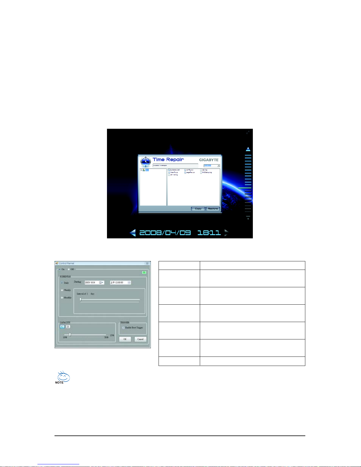
GA-EX58-EXTREME Motherboard - 86 -
4-6 Time Repair
Based on the Microsoft Volume Shadow Copy Services technology, Time Repair allows you to
quickly back up and restore your system data in the Windows Vista operating system. Time Repair
supports NTFS file system and can restore system data on PATA and SATA hard drives.
System Restore
Choose a system restore point using the navigation bar on the right or at the bottom of the screen to
view the system data backed up at different time. You can choose file(s)/directory(ies) and click the
Copy button to restore the file(s)/directory(ies) or click Restore to restore the entire system.
Button Function
ON Automatically creates system restore
points
OF F DO NOT automatically create system
restore points
SCHEDULE Sets a regular interval for creating
system restore points
CAPACITY Sets the percentage of hard drive space
used for saving shadow copies
TRIGGER Creates a system restore point upon the
first boot up of the day
? Displays the Time Repair help file
Preference Screen:
• The hard drive used must have more than 1 GB of capacity and over 300 MB of available space.
• Each storage volume can accommodate 64 shadow copies. When this limit is reached, the
oldest shadow copy will be deleted and unable to be restored. Shadow copies are read-only
so you cannot edit the contents of a shadow copy.
Page 87
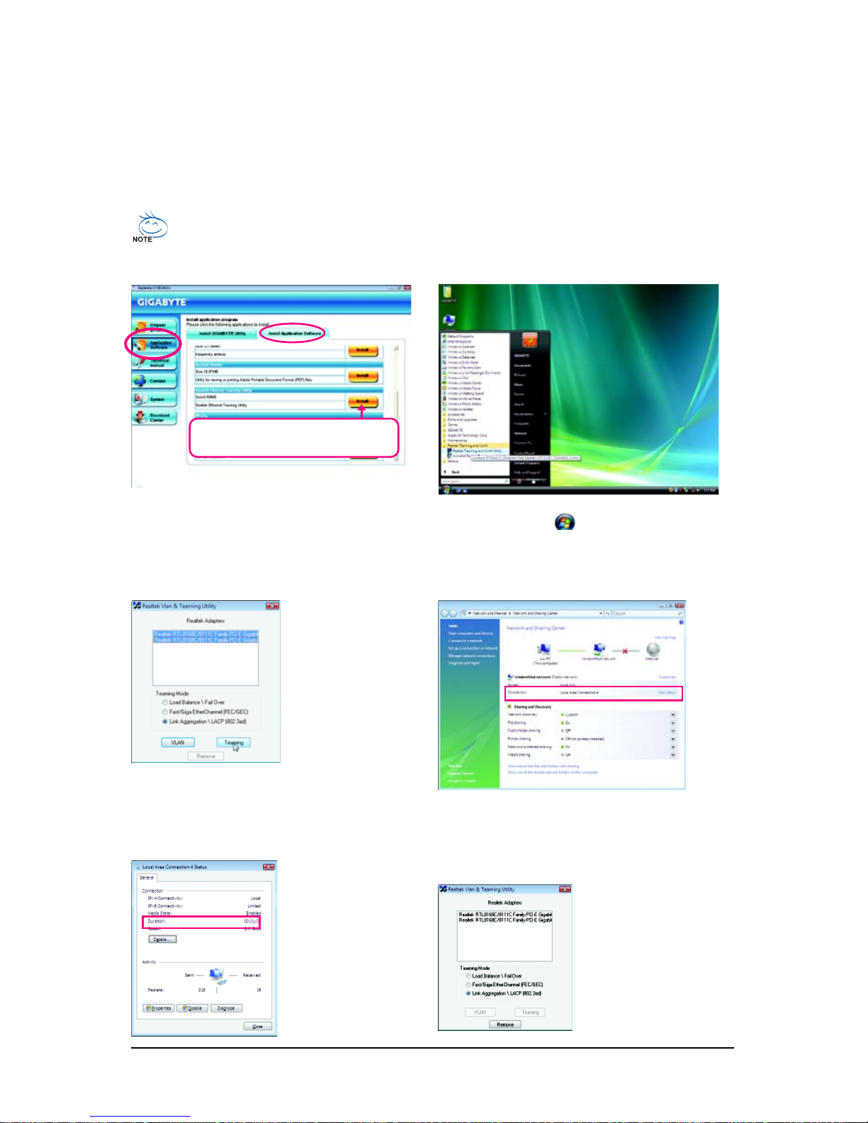
Unique Features- 87 -
4-7 Teaming
Dual LAN with Teaming functionality enabled on this motherboard allows two single connections to act as
one single connection for twice the transmission bandwidth, making data transmission more effective and
improving the quality of transmission of distant image(s). Fault tolerance on the dual LAN network
prevents network downtime by transferring the workload from a failed port to a working port.
• The speed of transmission is subject to the actual network environment or status even with Teaming enabled.
• T o enable Teaming or Bonding (IEEE 802.3ad Link Aggregation) feature, it is required the connected network switch
or router device supports the IEEE 802.3ad LACP standard. Please refer to your network switch or router device
manual for further details.
Select Realtek Ethernet Teaming Utility and
click Install.
Step 1:
Insert the motherboard driver disk and select Appli-
cation Software, Install Application Software.
Click Install under Realtek Ethernet Teaming Util-
ity for installation. Restart your system when completed.
Step 2:
Click the Start icon . Point to All Programs,
Realtek Teaming and VLAN, Realtek Teaming
and VLAN Utility to access the utility.
Step 3:
Select the two adapters
and set up the Teaming
mode based on your
hub's specifications.
Then click the Team-
ing button. (Two dialog boxes will appear
during the setup
Step 4:
After the Teaming is created, you will see only
one connection in Network and Sharing Center.
process, click OK to continue). When the Create
Virtual Adapter For Teaming Complete dialog
box appears, click OK to complete.
Step 5:
Click View status in
Network and Sharing
Center and you will see
the connection speed is
2.0 Gbps.
If you want to remove the
existing Teaming, access the Realtek Vlan
& Teaming Utility and
click the Remove button.
Removing the Existing Teaming:
Page 88

GA-EX58-EXTREME Motherboard - 88 -
Page 89

Appendix- 89 -
(Note 1) Skip this step if you do not want to create RAID array on the SATA controller.
(Note 2) For ICH10R SATA controller only.
Chapter 5 Appendix
5- 1 Configuring SATA Hard Drive(s)
To configure SATA hard drive(s), follow the steps below:
A. Install SATA hard drive(s) in your computer.
B. Configure SATA controller mode in BIOS Setup.
C . Configure a RAID array in RAID BIOS.
(Note 1)(Note 2)
D. Make a floppy disk containing the SATA RAID/AHCI driver.
(Note 2)
E. Install the SATA RAID/AHCI driver and operating system.
(Note 2)
Before you begin
Please prepare:
• At least two SATA hard drives (to ensure optimal performance, it is recommended that you use
two hard drives with identical model and capacity). If you do not want to create RAID, you may
prepare only one hard drive.
• An empty formatted floppy disk.
• Windows Vista/XP setup disk.
• Motherboard driver disk.
5-1-1 Configuring Intel ICH10R SATA Controllers
A. Installing SATA hard drive(s) in your computer
Attach one end of the SATA signal cable to the rear of the SATA hard drive and the other end to available
SATA port on the motherboard. If there is more than one SATA controller on your motherboard, refer to
"Chapter 1," "Hardware Installation," to identify the SATA controller for the SATA port. (For example, on
this motherboard, the SATA2_0, SATA2_1, SATA2_2, SATA2_3, SATA2_4 and SATA2_5 ports are
supported by ICH10R South Bridge.) Then connect the power connector from your power supply to the
hard drive.
Page 90
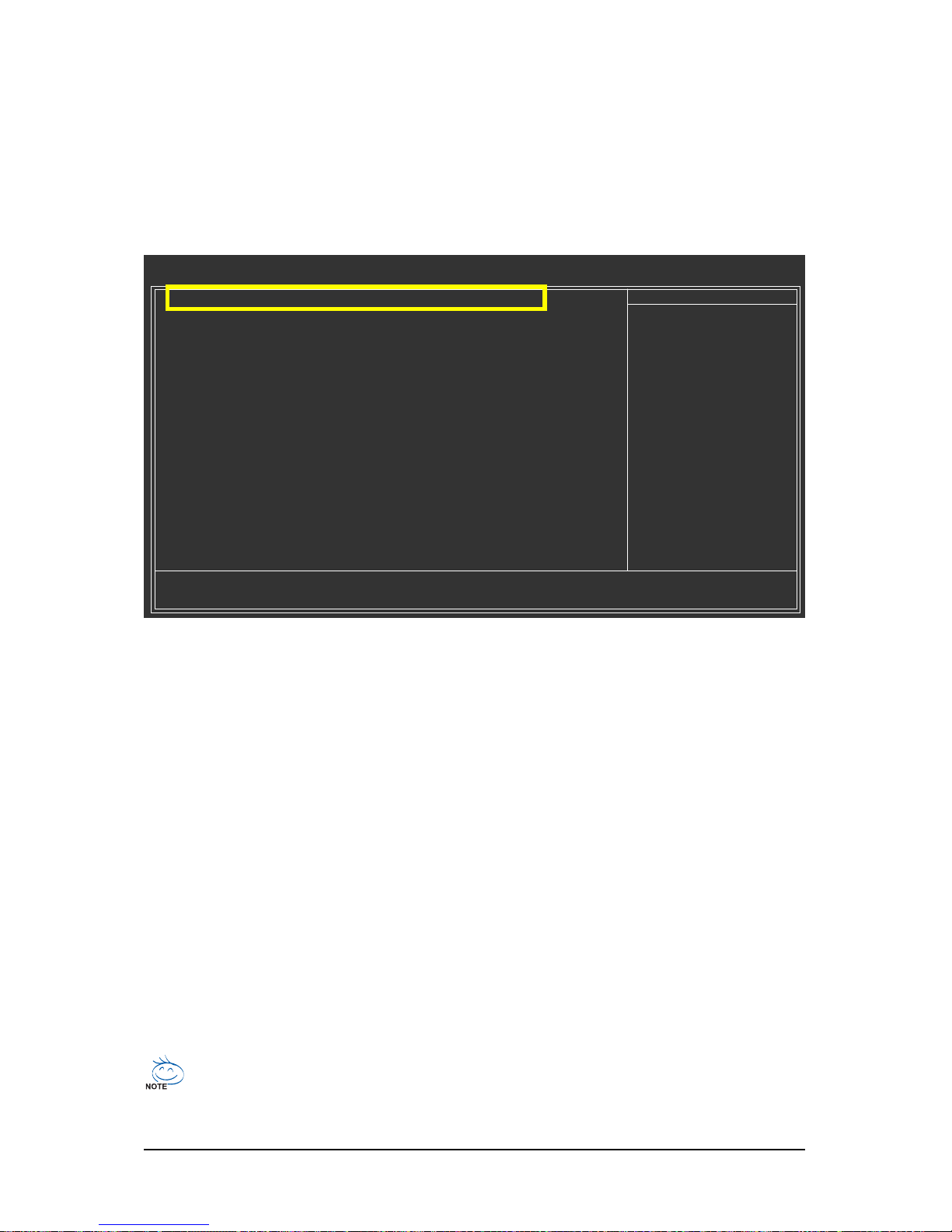
GA-EX58-EXTREME Motherboard - 90 -
B. Configuring SATA controller mode in BIOS Setup
Make sure to configure the SATA controller mode correctly in system BIOS Setup .
Step 1:
Turn on your computer and press <Delete> to enter BIOS Setup during the POST (Power-On Self-Test).
To create RAID, set SATA RAID/AHCI Mode under the Integrated Peripherals menu to RAID
(Figure 1)(Disabled by default). If you do not want to create RAID, set this item to Disabled or AHCI.
Figure 1
The BIOS Setup menus described in this section may differ from the exact settings for your
motherboard. The actual BIOS Setup menu options you will see shall depend on the motherboard
you have and the BIOS version.
Step 2:
Save changes and exit BIOS Setup.
CMOS Setup Utility-Copyright (C) 1984-2008 Award Software
Integrated Peripherals
SATA RAID/AHCI Mode [RAID]
SATA Port0-3 Native Mode [Disabled]
USB 1.0 Controller [Enabled]
USB 2.0 Controller [Enabled]
USB Keyboard Function [Disabled]
USB Mouse Function [Disabled]
USB Storage Function [Enabled]
Azalia Codec [Auto]
Onboard H/W 1394 [Enabled]
Onboard H/W LAN1 [Enabled]
Onboard H/W LAN2 [Enabled]
Green LAN [Disabled]
SMART LAN1 [Press Enter]
SMART LAN2 [Press Enter]
Onboard LAN1 Boot ROM [Disabled]
Onboard LAN2 Boot ROM [Disabled]
Onboard SATA/IDE Device [Enabled]
Onboard SATA/IDE Ctrl Mode [IDE]
Smart Backup [Press Enter]
: Move Enter: Select +/-/PU/PD: Value F10: Save ESC: Exit F1: General Help
F5: Previous Values F6: Fail-Safe Default F7: Optimized Defaults
Item Help
Menu Level
Page 91
Appendix- 91 -
C. Configuring a RAID array in RAID BIOS
Enter the RAID BIOS setup utility to configure a RAID array. Skip this step and proceed with the
installation of Windows operating system for a non-RAID configuration.
Step 1:
After the POST memory test begins and before the operating system boot begins, look for a message
which says "Press <Ctrl-I> to enter Configuration Utility" (Figure 2). Press <Ctrl> + <I> to enter the RAID
Configuration Utility.
Step 2:
After you press <Ctrl> + <I>, the MAIN MENU screen will appear (Figure 3).
Create RAID Volume
If you want to create a RAID array, select Create RAID Volume in MAIN MENU and press <Enter>.
Figure 2
Figure 3
Intel(R) Matrix Storage Manager option ROM v8.0.0.1039 ICH10R wRAID5
Copyright(C) 2003-08 Intel Corporation. All Rights Reversed.
RAID Volumes :
None defined.
Physical Disks :
Port Drive Model Serial # Size Type/Status(Vol ID)
0 ST3120026AS 3JT354CP 111.7GB Non-RAID Disk
1 ST3120026AS 3JT329JX 111.7GB Non-RAID Disk
Press <CTRL - I> to enter Configuration Utility..
Intel(R) Matrix Storage Manager option ROM v8.0.0.1039 ICH10R wRAID5
Copyright(C) 2003-08 Intel Corporation. All Rights Reversed.
[ MAIN MENU ]
1. Create RAID Volume
2. Delete RAID Volume
[ DISK/VOLUME INFORMATION ]
RAID Volumes :
None defined.
Physical Disks :
Port Drive Model Serial # Size Type/Status(Vol ID)
0 ST3120026AS 3JT354CP 111.7GB Non-RAID Disk
1 ST3120026AS 3JT329JX 111.7GB Non-RAID Disk
[]-Select [ESC]-Exit [ENTER]-Select Menu
3. Reset Disks to Non-RAID
4. Exit
Page 92
GA-EX58-EXTREME Motherboard - 92 -
Step 3:
After entering the CREATE VOLUME MENU screen, enter a volume name with 1~16 letters (letters
cannot be special characters) under the Name item and press <Enter>. Then, select a RAID level
(Figure 4). There are four RAID levels supported: RAID 0, RAID 1, RAID 10 and RAID 5 (the selections
available depend on the number of the hard drives being installed). Press <Enter> to proceed.
Step 4:
Under Disks item, select the hard drives to be included in the RAID array. If only two hard drives are
installed, they will be automatically assigned to the array. Set the stripe block size (Figure 5) if
necessary. The stripe block size can be set from 4 KB to 128 KB. Once you have selected the stripe
block size, press <Enter>.
Figure 5
Figure 4
Intel(R) Matrix Storage Manager option ROM v8.0.0.1039 ICH10R wRAID5
Copyright(C) 2003-08 Intel Corporation. All Rights Reversed.
[ CREATE VOLUME MENU ]
[ HELP ]
The following are typical values:
RAID0 - 128KB
RAID10- 64KB
RAID5 - 64KB
[]-Change [TAB]-Next [ESC]-Previous Menu [ENTER]-Select
Name : Volume0
RAID Level : RAID0(Stripe)
Disks : Select Disks
Strip Size : 128KB
Capacity : 223.6 GB
Create Volume
Intel(R) Matrix Storage Manager option ROM v8.0.0.1039 ICH10R wRAID5
Copyright(C) 2003-08 Intel Corporation. All Rights Reversed.
[ CREATE VOLUME MENU ]
[ HELP ]
Choose the RAID level:
RAID0: Stripes data (performance).
RAID1: Mirrors data (redundancy).
RAID10: Mirrors data and stripes the mirror.
RAID5: Stripes data and parity.
[]-Change [TAB]-Next [ESC]-Previous Menu [ENTER]-Select
Name : Volume0
RAID Level : RAID0(Stripe)
Disks : Select Disks
Strip Size : 128KB
Capacity : 223.6 GB
Create Volume
Page 93
Appendix- 93 -
Step 5:
Enter the array capacity and press <Enter>. Finally press <Enter> on the Create Volume item to begin
creating the RAID array. When prompted to confirm whether to create this volume, press <Y> to confirm
or <N> to cancel (Figure 6).
Figure 6
Intel(R) Matrix Storage Manager option ROM v8.0.0.1039 ICH10R wRAID5
Copyright(C) 2003-08 Intel Corporation. All Rights Reversed.
[ CREATE VOLUME MENU ]
[ HELP ]
Press ENTER to create the specified volume.
[]-Change [TAB]-Next [ESC]-Previous Menu [ENTER]-Select
Name : RAID_Volume0
RAID Level : RAID0(Stripe)
Disks : Select Disks
Strip Size : 128KB
Capacity : 223.6 GB
Create Volume
WARNING : ALL DATA ON SELECTED DISKS WILL BE LOST.
Are you sure you want to create this volume? (Y/N) :
When completed, you can see detailed information about the RAID array in the DISK/VOLUME
INFORMATION section, including the RAID level, stripe block size, array name, and array capacity,
etc. (Figure 7)
Figure 7
Intel(R) Matrix Storage Manager option ROM v8.0.0.1039 ICH10R wRAID5
Copyright(C) 2003-08 Intel Corporation. All Rights Reversed.
[ MAIN MENU ]
[ DISK/VOLUME INFORMATION ]
RAID Volumes :
ID Name Level Strip Size Status Bootable
0 Volume0 RAID0(Stripe) 128KB 223.6GB Normal Yes
Physical Disks :
Port Drive Model Serial # Size Type/Status(Vol ID)
0 ST3120026AS 3JT354CP 111.8GB Member Disk(0)
1 ST3120026AS 3JT329JX 111.8GB Member Disk(0)
[]-Select [ESC]-Exit [ENTER]-Select Menu
1. Create RAID Volume
2. Delete RAID Volume
3. Reset Disks to Non-RAID
4. Exit
To exit the ICH10R RAID BIOS utility, press <Esc> or select Exit in MAIN MENU.
Now, you can proceed to create the SATA RAID/AHCI driver diskette and install the SATA RAID/ACHI
driver and operating system.
Page 94
GA-EX58-EXTREME Motherboard - 94 -
Delete RAID Volume
To delete a RAID array, select Delete RAID Volume in MAIN MENU and press <Enter>. In the
DELETE VOLUME MENU section, use the up or down arrow key to select the array to be deleted and
press <Delete>. When prompted to confirm your selection (Figure 8), press <Y> to confirm or <N> to
abort.
Figure 8
Intel(R) Matrix Storage Manager option ROM v8.0.0.1039 ICH10R wRAID5
Copyright(C) 2003-08 Intel Corporation. All Rights Reversed.
[ DELETE VOLUME MENU ]
[ HELP ]
Deleting a volume will reset the disks to non-RAID.
WARNING: ALL DISK DATA WILL BE DELETED.
[]-Select [ESC]-Previous Menu [DEL]-Delete Volume
Name Level Drives Capacity Status Bootable
Volume0 RAID0(Stripe) 2 223.6GB Normal Yes
ALL DATA IN THE VOLUME WILL BE LOST!
Are you sure you want to delete "Volume0"? (Y/N) :
[ DELETE VOLUME VERIFICATION ]
Page 95
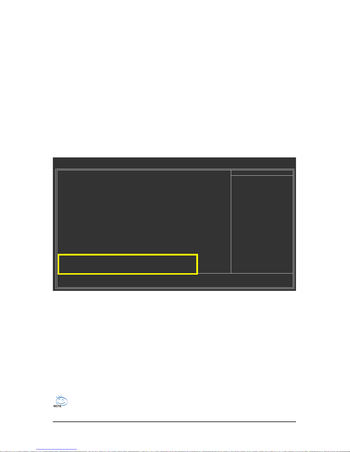
Appendix- 95 -
5-1-2 Configuring GIGABYTE SATA2/JMB322 SAT A Controller
A. Installing SATA hard drive(s) in your computer
Attach one end of the SATA signal cable to the rear of the SATA hard drive and the other end to available SATA
port on the motherboard. On this motherboard, the GSATA2_0~3 ports are supported by the GIGABYTE SATA2/
JMB322 SATA controller.) Then connect the power connector from your power supply to the hard drive.
B. Enabling the SATA controllers and configuring hard drive mode in BIOS Setup
Make sure to enable the SATA controllers and configure hard drive mode in system BIOS Setup.
Step 1:
Turn on your computer and press <Delete> to enter BIOS Setup during the POST. In BIOS Setup, go to
Integrated Peripherals, ensure that Onboard SATA/IDE Device is enabled. (We recommend that
you leave Onboard SATA/IDE Ctrl Mode to the default IDE mode.)
The BIOS Setup menus described in this section may differ from the exact settings for your
motherboard. The actual BIOS Setup menu options you will see shall depend on the motherboard
you have and the BIOS version.
Step 2:
Press <Enter> on Smart Backup and go to the Controller 0 (GSATA2 0/1) or Controller 1 (GSATA 2
2/3) submenu, depending on which ports you want to use (Controller 0 (GSATA2 0/1) controls the
GSATA2_0~1 ports and Controller 1 (GSATA2 2/3) controls the GSATA2_2~3 ports). Then enter the
Smart Backup Config submenu (Figure 2).
Figure 1
SATA RAID/AHCI Mode [Disabled]
SATA Port0-3 Native Mode [Disabled]
USB 1.0 Controller [Enabled]
USB 2.0 Controller [Enabled]
USB Keyboard Function [Disabled]
USB Mouse Function [Disabled]
USB Storage Function [Enabled]
Azalia Codec [Auto]
Onboard H/W 1394 [Enabled]
Onboard H/W LAN1 [Enabled]
Onboard H/W LAN2 [Enabled]
Green LAN [Disabled]
SMART LAN1 [Press Enter]
SMART LAN2 [Press Enter]
Onboard LAN1 Boot ROM [Disabled]
Onboard LAN2 Boot ROM [Disabled]
Onboard SATA/IDE Device [Enabled]
Onboard SATA/IDE Ctrl Mode [IDE]
Smart Backup [Press Enter]
: Move Enter: Select +/-/PU/PD: Value F10: Save ESC: Exit F1: General Help
F5: Previous Values F6: Fail-Safe Defaults F7: Optimized Defaults
CMOS Setup Utility-Copyright (C) 1984-2007 Award Software
Integrated Peripherals
Item Help
Menu Level
Step 3:
Select a RAID mode for your hard drives on the Smart Backup Config item (options include Performance (RAID 0), Safe (RAID 1), Big (JBOD) and Normal (Port Multiplier) and use Apply RAID Config
for the settings to take effect.
Page 96
GA-EX58-EXTREME Motherboard - 96 -
Figure 2
Step 4:
After configuring the SATA ports, you are ready to proceed with the installation of the operating system.
You do not have to load the SATA controller driver during the installation process of the operating
system. Make sure to install the driver after the operating system is installed (using "Xpress Install" to
install all drivers required for your motherboard is recommended) for the SATA hard drives to work and
be detected properly.
Step 5:
Then install the Smart Backup utility from the Application Software menu on the driver Autorun screen
for monitoring the device/RAID status in the operating system (for more information, refer to section 51-5, "Smart Backup Utility").
CMOS Setup Utility-Copyright (C) 1984-2008 Award Software
Smart Backup Config
Item Help
Menu Level
Smart Backup Config [P erformance (RAID 0)]
Apply RAID Config [Press Enter]
=== Disk Info ===
[Port] [Model] [Capacity]
Port 0 WDCWD800JD-00JNA0 80GB
Port 1 WDCWD800JD-22LSA0 80GB
=== RAID Info ===
[Level] [Capacity] [Member]
Performance 0GB
: Move Enter: Select +/-/PU/PD: Value F10: Save ESC: Exit F1: General Help
F5: Previous Values F6: Fail-Safe Defaults F7: Optimized Defaults
Page 97
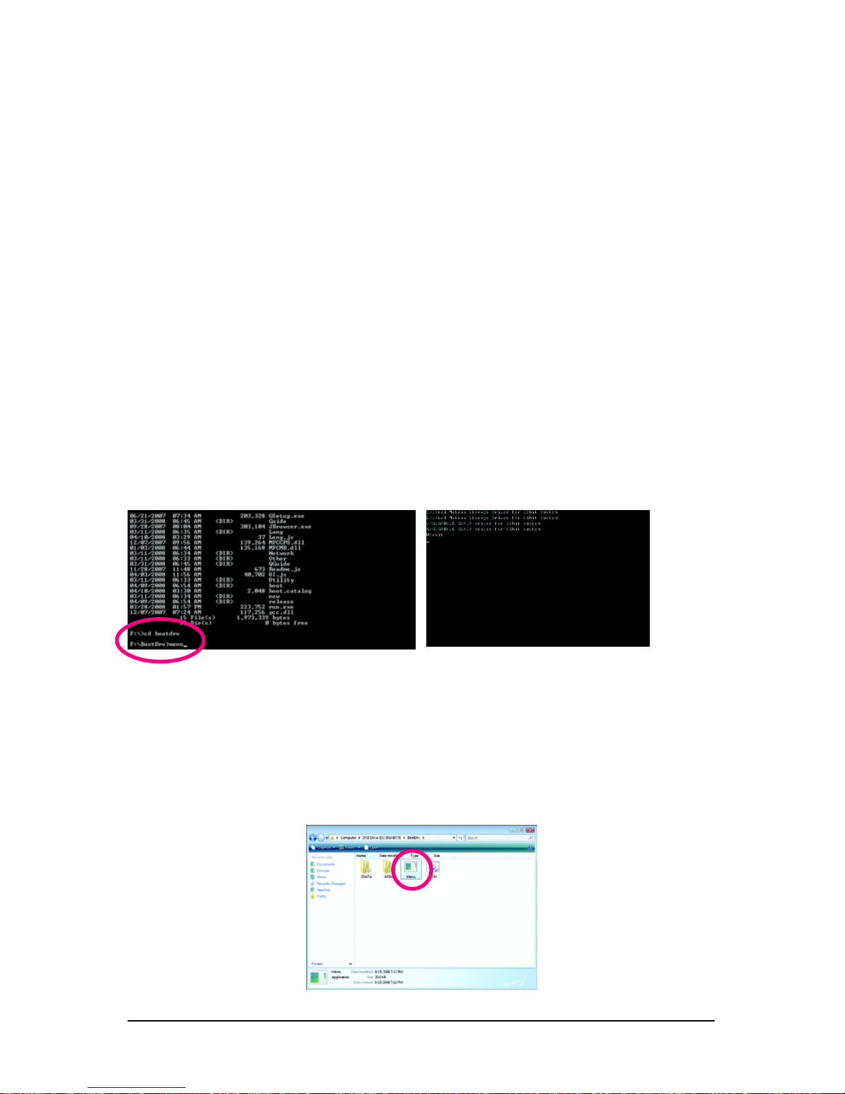
Appendix- 97 -
5-1-3 Making a SAT A RAID/AHCI Driver Diskette
(Required for AHCI and RAID Mode)
To successfully install operating system onto SATA hard drive(s) that is/are configured to RAID/AHCI
mode, you need to install the SATA controller driver during the OS installation. Without the driver, the
hard drive may not be recognized during the Windows setup process. First of all, copy the driver for
the SATA controller from the motherboard driver disk to a floppy disk. For installing Windows Vista, you
also can copy the SATA controller driver from the motherboard driver disk to a USB flash drive. See the
instructions below about how to copy the driver in MS-DOS mode
(Note 1)
. Prepare a startup disk that has
CD-ROM support and a blank formatted floppy disk.
Step 1: Insert the prepared startup disk and motherboard driver disk in your system. Boot from the
startup disk. Once at the A:\> prompt, change to your optical drive (example: D:\>). At the D:\> prompt,
type the following two commands. Press <Enter> after each command (Figure 1):
cd bootdrv
menu
Step 2: When the controller menu (Figure 2) appears, remove the startup disk and insert the blank
formatted disk. Select the controller driver by pressing the corresponding letter from the menu and press
<Enter>. For example, from the menu in Figure 2, for Intel ICH10R SATA controllers, select 1)Intel
Matrix Storage driver for 32bit system for Windows 32-bit operating system or 2)Intel Matrix
Storage driver for 64bit system for Windows 64-bit
(Note 2)
. Your system will then automatically zip and
transfer this driver file to the floppy disk. Press any key to exit when finished.
(Note 1) For users without a startup disk:
Use an alternative system and insert the motherboard driver disk. From your optical drive
folder, double click the Menu.exe file in the BootDrv folder (Figure 3). A command prompt
window will open similar to that in Figure 2.
(Note 2) The GIGABYTE GSATA drivers in the menu in Figure 2 are required if you want to install
the Windows operating system onto hard drives that are connected to the GIGABYTE SATA2/
JMB322 controller and configured to AHCI mode in BIOS Setup. For installation of the driver
during the OS installation, refer to section 5-1-4.
Figure 1 Figure 2
Figure 3
Page 98
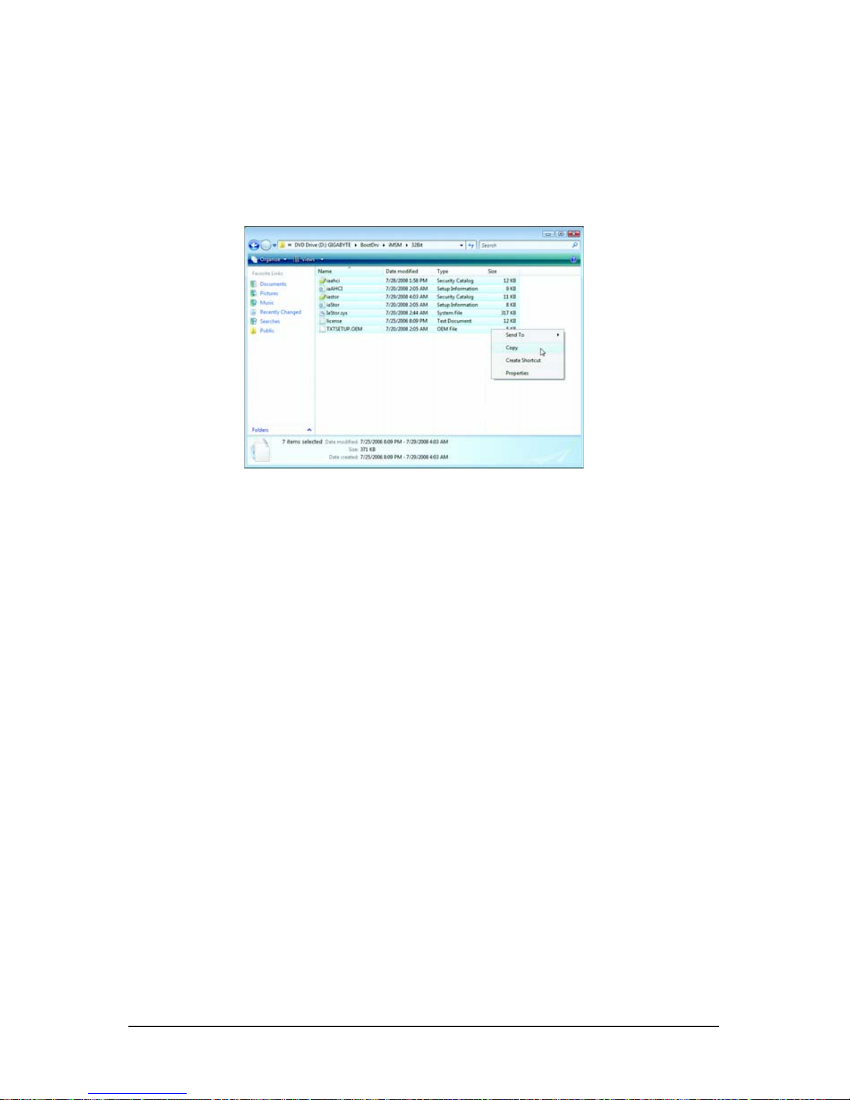
GA-EX58-EXTREME Motherboard - 98 -
Copying the SA TA RAID/AHCI driver from the motherboard driver disk to a USB flash drive
On an alternative system, copy the SATA RAID/AHCI driver to your USB flash drive from the motherboard
driver disk. For example, to install the Windows Vista 32-bit operating system
(Note)
onto hard drives
connected to the ICH10R SATA controller, copy all of the files (Figure 4) located in the
BootDrv\iMSM\32Bit directory in the motherboard driver disk to your USB flash drive.
(Note) To install the Windows Vista 64-bit operating system, please copy the files in the
BootDrv\iMSM\64Bit directory
Figure 4
Page 99

Appendix- 99 -
Figure 1
Step 2:
Then a controller menu similar to Figure 2 below will appear. Select Intel(R) ICH8R/ICH9R/ICH10R/
DO SATA RAID Controller and press <Enter>. On the next screen, press <Enter> to continue the
driver installation. After the driver installation, you can proceed with the Windows XP installation.
Windows Setup
Press F6 if you need to install a third party SCSI or RAID driver.
5-1-4 Installing the SATA RAID/AHCI Driver and Operating System
With the SATA RAID/AHCI driver diskette and correct BIOS settings, you are ready to install Windows
Vista/XP onto your hard drive(s). The followings are examples of Windows XP and Vista installation on
the Intel ICH10R SATA controller.
A. Installing Windows XP
Step 1:
Restart your system to boot from the Windows XP setup disk and press <F6> as soon as you see the
message "Press F6 if you need to install a 3rd party SCSI or RAID driver" (Figure 1). A screen will then
appear asking you to specify additional device. Insert the floppy disk containing the SATA RAID/AHCI
driver and press <S>.
Figure 2
Windows Setup
ENTER=Select F3=Exit
You have chosen to configure a SCSI Adapter for use with Windows,
using a device support disk provided by an adapter manufacturer.
Select the SCSI Adapter you want from the following list, or press ESC
to return to the previous screen.
Intel(R) ICH7R/DH SATA RAID Controller
Intel(R) ICH7MDH SATA RAID Controller
Intel(R) ICH8R/ICH9R/ICH10R/DO SATA RAID Controller
Intel(R) ICH8M-E/ICH9M-E SATA RAID Controller
Page 100
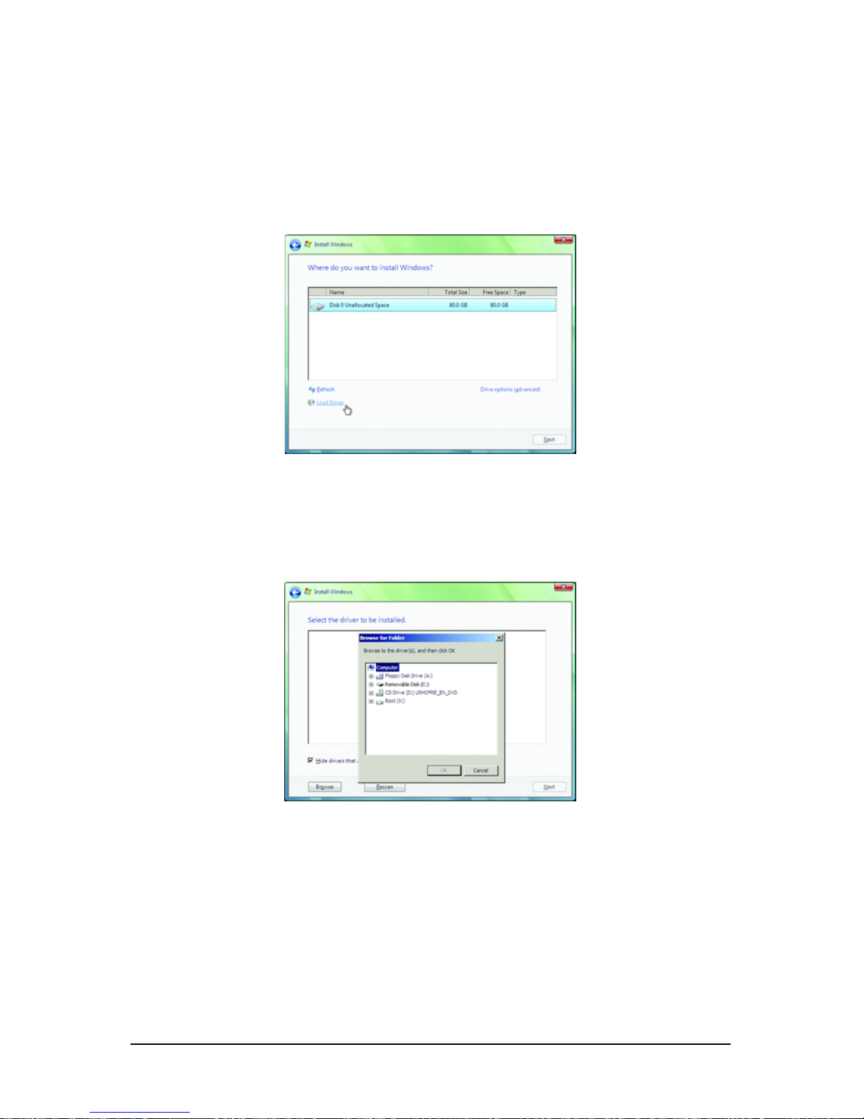
GA-EX58-EXTREME Motherboard - 100 -
B. Installing Windows Vista
(The procedure below assumes that only one RAID array exists in your system.)
Step 1:
Restart your system to boot from the Windows Vista setup disk and perform standard OS installation
steps. When a screen similar to that below appears, select Load Driver. (Figure 3).
Step 2:
Specify the location where the driver is saved, such as your floppy disk or USB flash drive (Figure 4).
Figure 4
Figure 3
 Loading...