

Page 1

GA-990FXA-UD7
User's Manual
Rev. 1001
12ME-990FXA7-1001R
Page 2
Motherboard
GA-990FXA-UD7
May 13, 2011
May 13, 2011
Motherboard
GA-990FXA-UD7
Page 3
Copyright
© 2011 GIGA-BYTE TECHNOLOGY CO., LTD. All rights reserved.
The trademarks mentioned in this manual are legally registered to their respective owners.
Disclaimer
Information in this manual is protected by copyright laws and is the property of GIGABYTE.
Changes to the specications and features in this manual may be made by GIGABYTE with-
out prior notice. No part of this manual may be reproduced, copied, translated, transmitted, or
published in any form or by any means without GIGABYTE's prior written permission.
Documentation Classications
In order to assist in the use of this product, GIGABYTE provides the following types of documentations:
For quick set-up of the product, read the Quick Installation Guide included with the product.
For detailed product information, carefully read the User's Manual.
For product-related information, check on our website at:
http://www.gigabyte.com
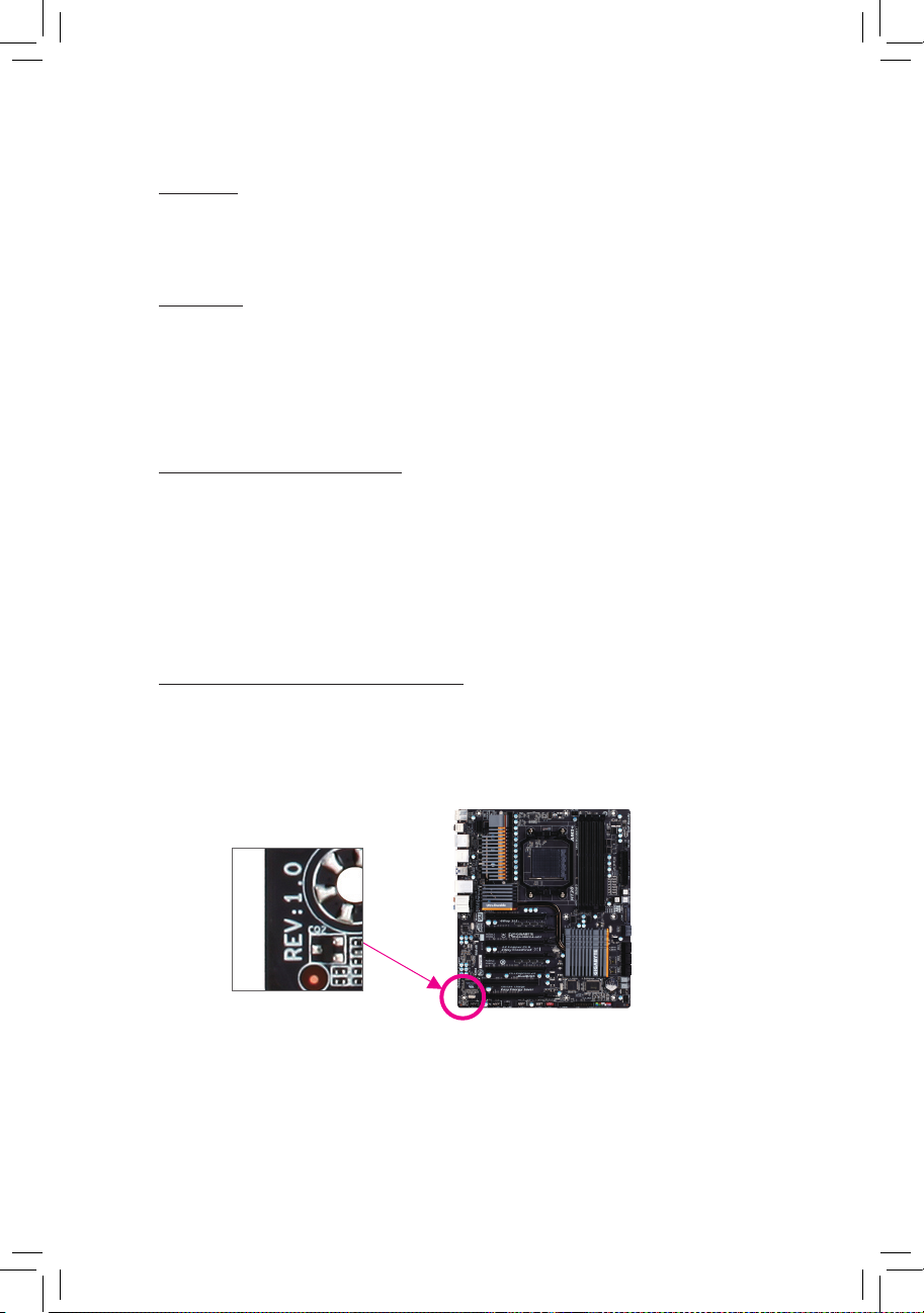
Identifying Your Motherboard Revision
The revision number on your motherboard looks like this: "REV: X.X." For example, "REV: 1.0"
means the revision of the motherboard is 1.0. Check your motherboard revision before updating
motherboard BIOS, drivers, or when looking for technical information.
Example:
Page 4

- 4 -
Table of Contents
Box Contents ...................................................................................................................6
Optional Items .................................................................................................................6
GA-990FXA-UD7 Motherboard Layout
............................................................................7
GA-990FXA-UD7 Motherboard Block Diagram ...............................................................8
Chapter 1 Hardware Installation .....................................................................................9
1-1 Installation Precautions .................................................................................... 9
1-2 Product Specications .................................................................................... 10
1-3 Installing the CPU and CPU Cooler ............................................................... 13
1-3-1 Installing the CPU ...................................................................................................13
1-3-2 Installing the CPU Cooler .......................................................................................15
1-4 Installing the Memory ..................................................................................... 16
1-4-1 Dual Channel Memory Conguration .....................................................................16
1-4-2 Installing a Memory ...............................................................................................17
1-5 Installing an Expansion Card ......................................................................... 18
1-6 Setup of AMD CrossFireX™ Conguration...................................................... 19
1-7 Back Panel Connectors .................................................................................. 20
1-8 Onboard Buttons ............................................................................................ 22
1-9 Internal Connectors ........................................................................................ 23
Chapter 2 BIOS Setup ..................................................................................................33
2-1 Startup Screen ............................................................................................... 34
2-2 The Main Menu .............................................................................................. 35
2-3 MB Intelligent Tweaker(M.I.T.) ........................................................................ 37
2-4 Standard CMOS Features .............................................................................. 43
2-5 Advanced BIOS Features .............................................................................. 45
2-6 Integrated Peripherals .................................................................................... 48
2-7 Power Management Setup ............................................................................. 53
2-8 PC Health Status ............................................................................................ 55
2-9 Load Fail-Safe Defaults .................................................................................. 57
2-10 Load Optimized Defaults ................................................................................ 57
2-11 Set Supervisor/User Password ...................................................................... 58
2-12 Save & Exit Setup .......................................................................................... 59
2-13 Exit Without Saving ........................................................................................ 59
Page 5

- 5 -
Chapter 3 Drivers Installation ........................................................................................61
3-1 Installing Chipset Drivers ............................................................................... 61
3-2 Application Software ...................................................................................... 62
3-3 Technical Manuals .......................................................................................... 62
3-4 Contact ........................................................................................................... 63
3-5 System ........................................................................................................... 63
3-6 Download Center ........................................................................................... 64
3-7 New Utilities ................................................................................................... 64
Chapter 4 Unique Features ...........................................................................................65
4-1 Xpress Recovery2 .......................................................................................... 65
4-2 BIOS Update Utilities ..................................................................................... 68
4-2-1 Updating the BIOS with the Q-Flash Utility .............................................................68
4-2-2 Updating the BIOS with the @BIOS Utility .............................................................71
4-3 EasyTune 6 .................................................................................................... 72
4-4 Easy Energy Saver ........................................................................................ 73
4-5 Q-Share .......................................................................................................... 75
4-6 SMART Recovery........................................................................................... 76
4-7 Auto Green ..................................................................................................... 77
4-8 Cloud OC ....................................................................................................... 78
Chapter 5 Appendix ......................................................................................................79
5-1 Conguring SATA Hard Drive(s) .................................................................... 79
5-1-1 Conguring AMD SB950 SATA Controllers ............................................................79
5-1-2 Conguring Marvell 88SE9172 SATA Controllers ...................................................85
5-1-3 Installing the SATA RAID/AHCI Driver and Operating System ...............................91
5-2 Conguring Audio Input and Output ............................................................... 99
5-2-1 Conguring 2/4/5.1/7.1-Channel Audio ...................................................................99
5-2-2 Conguring S/PDIF Out ........................................................................................101
5-2-3 Enabling the Dolby Home Theater Function .........................................................102
5-2-4 Conguring Microphone Recording ......................................................................103
5-2-5 Using the Sound Recorder ...................................................................................105
5-3 Troubleshooting............................................................................................ 106
5-3-1 Frequently Asked Questions ................................................................................106
5-3-2 Troubleshooting Procedure ..................................................................................107
5-4 POST Error Code ......................................................................................... 109
Page 6
- 6 -
Box Contents
GA-990FXA-UD7 motherboard
Motherboard driver disk
User's Manual
Quick Installation Guide
Four SATA cables
I/O Shield
Two 2-Way CrossFireX bridge connectors
One 2-Way SLI bridge connector
(Note)
One 3-Way SLI bridge connector
(Note)
One 4-Way SLI bridge connector
(Note)
Optional Items
2-port USB 2.0 bracket (Part No. 12CR1-1UB030-5*R)
2-port SATA power cable (Part No. 12CF1-2SERPW-0*R)
2-port IEEE 1394a bracket (Part No. 12CF1-1IE008-0*R)
3.5" Front Panel with 2 USB 3.0/2.0 ports (Part No. 12CR1-FPX582-0*R)
• The box contents above are for reference only and the actual items shall depend on the product package you obtain.
The box contents are subject to change without notice.
• The motherboard image is for reference only.
(Note ) To enable NVIDIA SLI technology, you need SLI-supported graphics cards, BIOS, and driver. For more
details, please go to GIGABYTE's website.
Page 7
- 7 -
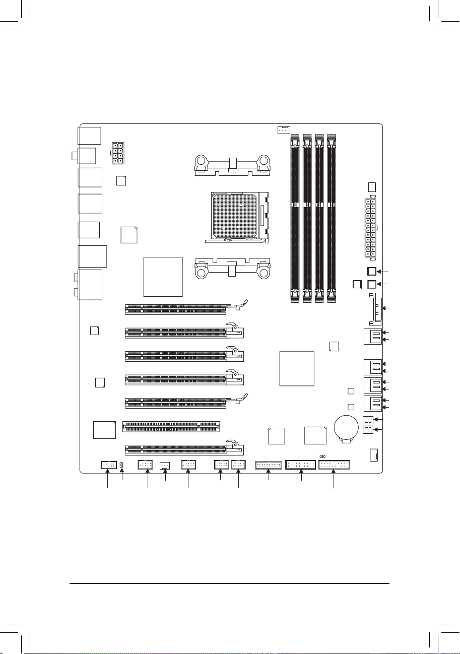
GA-990FXA-UD7 Motherboard Layout
(Note ) For error code information, please refer to Chapter 5.
CPU_FAN
ATX
GA-990FXA-UD7
DDR3_4
DDR3_2
ATX_12V
AMD 990FX
AMD SB950
PCI
BAT
PW_SW
PCIEX4_1
DDR3_3
DDR3_1
Socket AM3+
KB_MS_USB
AUDIO
R_SPDIF
USB_1394_ESATA
USB_LAN
USB_ESATA
Etron
EJ168
R_USB30
CODEC
CLR_CMOS
F_USB2 F_USB30
TPM
F_PANEL
F_USB1
iTE
IT8720
PCIEX16_1
PCIEX16_2
RST_SW
M_BIOS
B_BIOS
GSATA3_7
SATA3_4
SATA3_2
SATA3_0
GSATA3_6
SATA3_5
SATA3_3
SATA3_1
PWR_FAN
SYS_FAN1
Marvell
88SE9172
F_USB3
PCIEX8_1
PCIEX4_2
PCIEX8_2
TSR1
(Note)
TSL1
(Note)
Realtek
RTL8111E
Marvell
88SE9172
VIA
VT6308
Etron
EJ168
SYS_FAN2
F_1394
SPDIF_O
F_AUDIO
CMOS_SW
ATX4P
Page 8
- 8 -
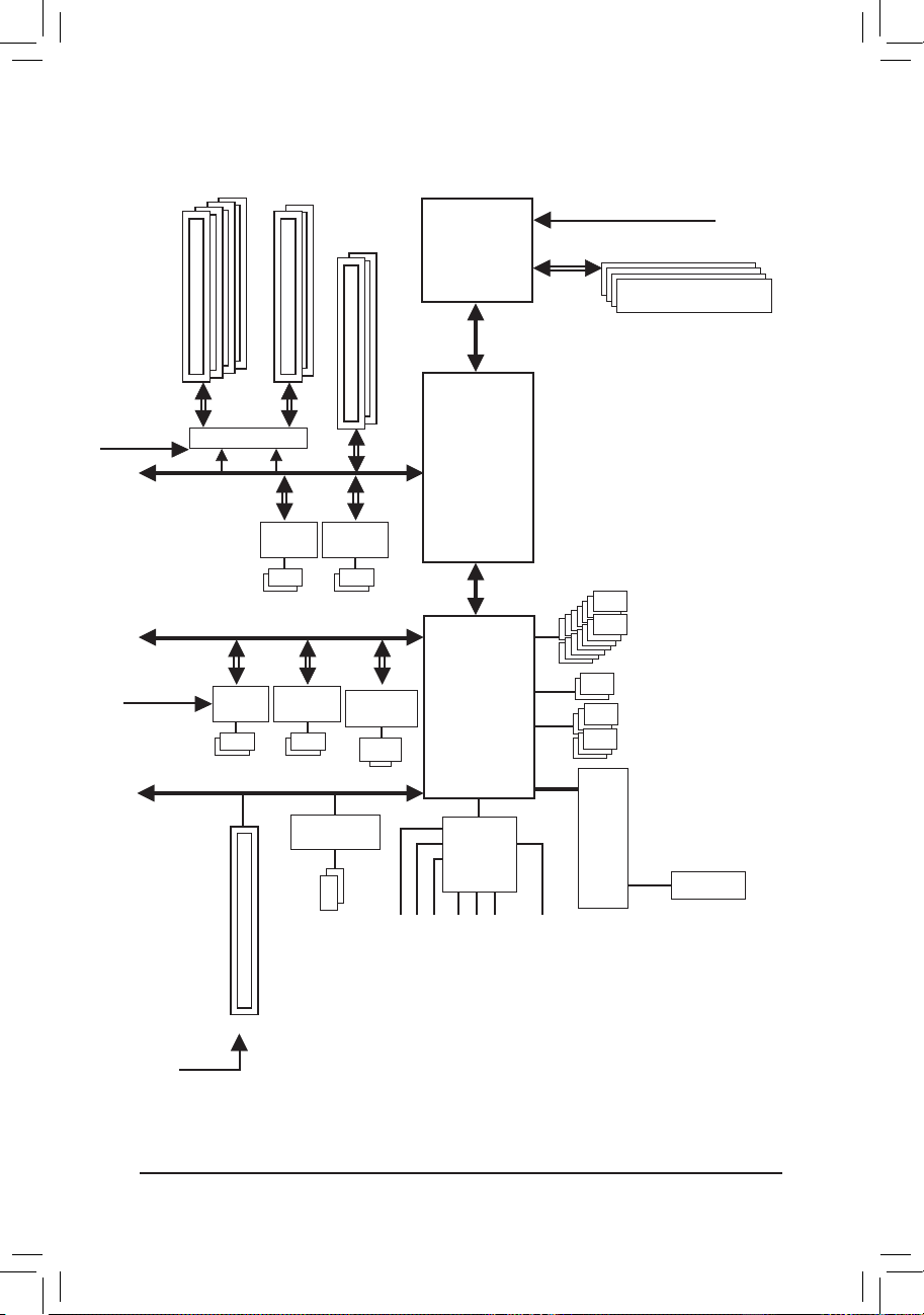
GA-990FXA-UD7 Motherboard Block Diagram
AM3+/AM3 CPU
Hyper Transport 3.0
AMD 990FX
PCI Express Bus
CPU CLK+/- (200 MHz)
DDR3 2000(O.C.)/1866/1600/1333/1066 MHz
Dual Channel Memory
AMD SB950
iTE
IT8720
LPC
Bus
6 SATA 6Gb/s
Center/Subwoofer Speaker Out
Line Out
MIC
Line In
S/PDIF Out
Side Speaker Out
Surround Speaker Out
CODEC
1 PCI
PCI Bus
PCI CLK
(33 MHz)
VIA VT6308
2 IEEE 1394a
Dual BIOS
PCIe CLK
(100 MHz)
2 PCI Express x16
4 PCI Express x8
Switch
or
x8 x16
2 PCI Express x4
x4
PCIe CLK
(100 MHz)
PCI Express Bus
RJ45
PS/2 KB/Mouse
Realtek
RTL8111E
14 USB 2.0/1.1
x1
Marvell
88SE9172
2 SATA 6Gb/s
x1
Etron
EJ168
2 USB 3.0/2.0
x1
x1
Marvell
88SE9172
2 SATA 6Gb/s
x1
Etron
EJ168
2 USB 3.0/2.0
Page 9

- 9 - Hardware Installation
1-1 Installation Precautions
The motherboard contains numerous delicate electronic circuits and components which can
become damaged as a result of electrostatic discharge (ESD). Prior to installation, carefully read
the user's manual and follow these procedures:
• Prior to installation, do not remove or break motherboard S/N (Serial Number) sticker or
warranty sticker provided by your dealer. These stickers are required for warranty validation.
• Always remove the AC power by unplugging the power cord from the power outlet before
installing or removing the motherboard or other hardware components.
• When connecting hardware components to the internal connectors on the motherboard,
make sure they are connected tightly and securely.
• When handling the motherboard, avoid touching any metal leads or connectors.
• It is best to wear an electrostatic discharge (ESD) wrist strap when handling electronic com-
ponents such as a motherboard, CPU or memory. If you do not have an ESD wrist strap,
keep your hands dry and rst touch a metal object to eliminate static electricity.
• Prior to installing the motherboard, please have it on top of an antistatic pad or within an
electrostatic shielding container.
• Before unplugging the power supply cable from the motherboard, make sure the power sup-
ply has been turned off.
• Before turning on the power, make sure the power supply voltage has been set according to
the local voltage standard.
• Before using the product, please verify that all cables and power connectors of your hard-
ware components are connected.
• To prevent damage to the motherboard, do not allow screws to come in contact with the
motherboard circuit or its components.
• Make sure there are no leftover screws or metal components placed on the motherboard or
within the computer casing.
• Do not place the computer system on an uneven surface
.
• Do not place the computer system in a high-temperature environment.
• Turning on the computer power during the installation process can lead to damage to sys-
tem components as well as physical harm to the user.
• If you are uncertain about any installation steps or have a problem related to the use of the
product, please consult a certied computer technician.
Chapter 1 Hardware Installation
Page 10
Hardware Installation - 10 -
1-2 Product Specications
CPU AM3+ Socket:
- AMD AM3+ FX processors
- AMD AM3 Phenom™ II processors/ AMD Athlon™ II processors
(Go to GIGABYTE's website for the latest CPU support list.)
Hyper Transport
Bus
5200 MT/s
Chipset
North Bridge: AMD 990FX
South Bridge: AMD SB950
Memory 4 x 1.5V DDR3 DIMM sockets supporting up to 32 GB of system memory
* Due to Windows 32-bit operating system limitation, when more than 4 GB of physical
memory is installed, the actual memory size displayed will be less than 4 GB.
Dual channel memory architecture
Support for DDR3 2000(O.C.)/1866/1600/1333/1066 MHz memory modules
* To support a DDR3 1866 MHz (and above) memory, you must install an AMD AM3+
CPU rst.
(Go to GIGABYTE's website for the latest supported memory speeds and memory
modules.)
Audio Realtek ALC889 codec
High Denition Audio
2/4/5.1/7.1-channel
Support for Dolby
®
Home Theater
Support for S/PDIF Out
LAN 1 x Realtek RTL8111E chip (10/100/1000 Mbit)
Expansion Slots 2 x PCI Express x16 slots, running at x16 (PCIEX16_1, PCIEX16_2)
* For optimum performance, if only one PCI Express graphics card is to be installed, be
sure to install it in the PCIEX16_1 slot; if you are installing two PCI Express graphics
cards, it is recommended that you install them in the PCIEX16_1 and PCIEX16_2
slots.
2 x PCI Express x16 slots, running at x8 (PCIEX8_1, PCIEX8_2)
* The PCIEX8_1 slot shares bandwidth with the PCIEX16_1 slot and the PCIEX8_2
slot with PCIEX16_2. The PCIEX16_1/PCIEX16_2 slot will operate at up to x8 mode
when the PCIEX8_1/PCIEX8_2 is populated.
2 x PCI Express x16 slots, running at x4 (PCIEX4_1, PCIEX4_2)
(All PCI Express slots conform to the PCI Express 2.0 standard.)
1 x PCI slot
Multi-Graphics
Technology
Support for 2-Way/3-Way/4-Way AMD CrossFireX
™
technology
Storage Interface South Bridge:
- 6 x SATA 6Gb/s connectors (SATA3_0~SATA3_5) supporting up to 6 SATA
6Gb/s devices
- Support for RAID 0, RAID 1, RAID 5, RAID 10, and JBOD
2 x Marvell 88SE9172 chips:
- 2 x SATA 6Gb/s connectors (GSATA3_6, GSATA3_7) supporting up to 2
SATA 6Gb/s devices
- Suppor t for RAID 0 and RAID 1
Page 11
- 11 - Hardware Installation
Storage Interface - 2 x eSATA 6Gb/s connectors (including 1 eSATA/USB Combo connector)
on the back panel supporting up to 2 SATA 6Gb/s devices
- Suppor t for RAID 0 and RAID 1
USB South Bridge:
- Up to 14 USB 2.0/1.1 ports (8 ports on the back panel, including 1 eSATA/
USB Combo connector, 6 por ts available through the internal USB
headers)
2 x Etron EJ168 chips:
- Up to 4 USB 3.0/2.0 ports (2 ports on the back panel, 2 ports available
through the internal USB header)
IEEE 1394 VIA VT6308 chip:
- Up to 2 IEEE 1394a ports (1 port on the back panel, 1 port available through
the internal IEEE 1394a header)
Internal
Connectors
1 x 24-pin ATX main power connector
1 x 8-pin ATX 12V power connector
1 x PCIe power connector
8 x SATA 6Gb/s connectors
1 x CPU fan header
2 x system fan headers
1 x power fan header
1 x front panel header
1 x front panel audio header
1 x S/PDIF Out header
3 x USB 2.0/1.1 headers
1 x USB 3.0/2.0 header
1 x IEEE 1394a header
1 x Trusted Platform Module (TPM) header
1 x clearing CMOS jumper
1 x clearing CMOS button
1 x power button
1 x reset button
Back Panel
Connectors
1 x PS/2 keyboard/mouse port
1 x optical S/PDIF Out connector
1 x coaxial S/PDIF Out connector
1 x IEEE 1394a port
7 x USB 2.0/1.1 ports
2 x USB 3.0/2.0 ports
1 x eSATA/USB Combo connector
1 x eSATA 6Gb/s connector
1 x RJ-45 port
6 x audio jacks (Center/Subwoofer Speaker Out/Rear Speaker Out/Side Speaker
Out/Line In/Line Out/Microphone)
I/O Controller iTE IT8720 chip
Page 12
Hardware Installation - 12 -
BIOS 2 x 32 Mbit ash
Use of licensed AWARD BIOS
Support for DualBIOS
™
PnP 1.0a, DMI 2.0, SM BIOS 2.4, ACPI 1.0b
Hardware
Monitor
System voltage detection
CPU/System temperature detection
CPU/System/Power fan speed detection
CPU overheating warning
CPU/System/Power fan fail warning
CPU/System fan speed control
* Whether the CPU/system fan speed control function is supported will depend on
the CPU/system cooler you install.
Unique Features Support for @BIOS
Support for Q-Flash
Support for Xpress BIOS Rescue
Support for Download Center
Support for Xpress Install
Support for Xpress Recovery2
Support for EasyTune
* Available functions in EasyTune may differ by motherboard model.
Support for Easy Energy Saver
Support for Smart Recovery
Support for Auto Green
Support for ON/OFF Charge
Support for Cloud OC
Support for 3TB+ Unlock
Support for Q-Share
Bundled
Software
Norton Internet Security (OEM version)
Operating
System
Support for Microsoft
®
Windows 7/Vista/XP
Form Factor ATX Form Factor; 30.5cm x 26.3cm
* GIG ABYT E reser ves the right to make any changes to the product specications and product-related informat ion
without prior notice.
Page 13
- 13 - Hardware Installation
1-3 Installing the CPU and CPU Cooler
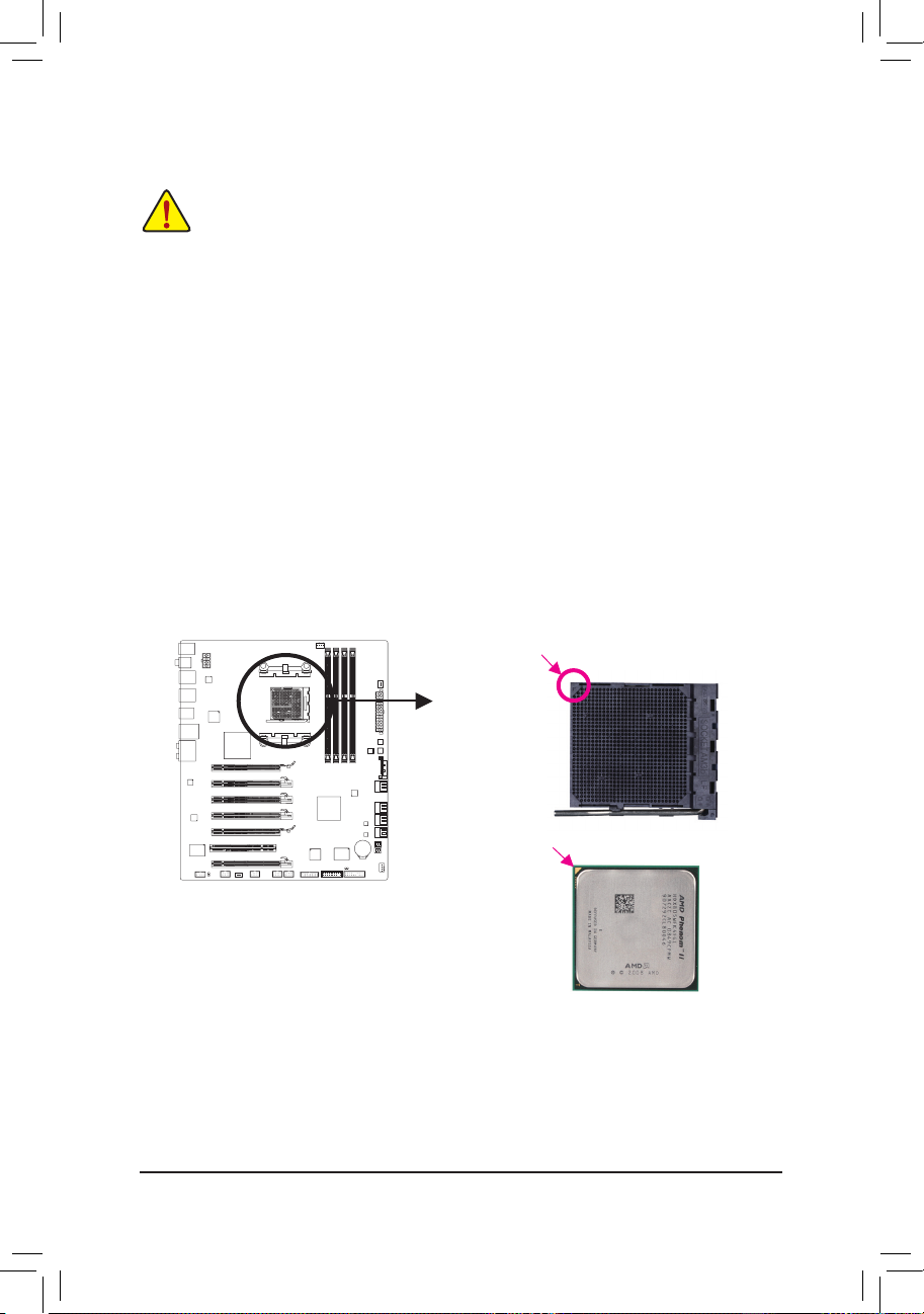
1-3-1 Installing the CPU
A. Locate the pin one (denoted by a small triangle) of the CPU socket and the CPU.
Read the following guidelines before you begin to install the CPU:
• Make sure that the motherboard supports the CPU.
(Go to GIGABYTE's website for the latest CPU support list.)
• Always turn off the computer and unplug the power cord from the power outlet before installing
the CPU to prevent hardware damage.
• Locate the pin one of the CPU. The CPU cannot be inserted if oriented incorrectly. (Or you may
locate the notches on both sides of the CPU and alignment keys on the CPU socket.)
• Apply an even and thin layer of thermal grease on the surface of the CPU.
• Do not turn on the computer if the CPU cooler is not installed, otherwise overheating and dam-
age of the CPU may occur.
• Set the CPU host frequency in accordance with the CPU specications. It is not recommended
that the system bus frequency be set beyond hardware specications since it does not meet the
standard requirements for the peripherals. If you wish to set the frequency beyond the standard
specications, please do so according to your hardware specications including the CPU, graphics card, memory, hard drive, etc.
AM3+/AM3 CPU
A Small Triangle Marking
Denotes CPU Pin One
AM3+ Socket
A Smal l Triangle Mark
Denotes Pin One of the
Socket
Page 14
Hardware Installation - 14 -
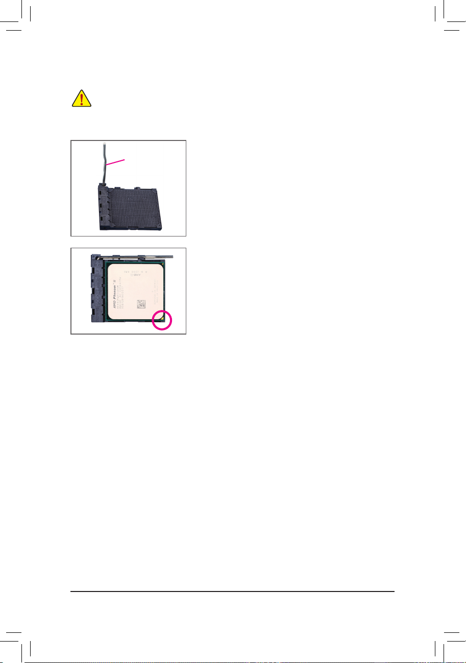
B. Follow the steps below to correctly install the CPU into the motherboard CPU socket.
• Before installing the CPU, make sure to turn off the computer and unplug the power cord from the
power outlet to prevent damage to the CPU.
• Do not force the CPU into the CPU socket. The CPU cannot t in if oriented incorrectly. Adjust the
CPU orientation if this occurs.
Step 1:
Completely lift up the CPU socket locking lever.
Step 2:
Align the CPU pin one (small triangle marking) with the triangle mark
on the CPU socket and gently insert the CPU into the socket. Make
sure that the CPU pins t perfectly into their holes. Once the CPU is
positioned into its socket, place one nger down on the middle of the
CPU, lowering the locking lever and latching it into the fully locked
position.
CPU Socket
Locking Lever
Page 15
- 15 - Hardware Installation
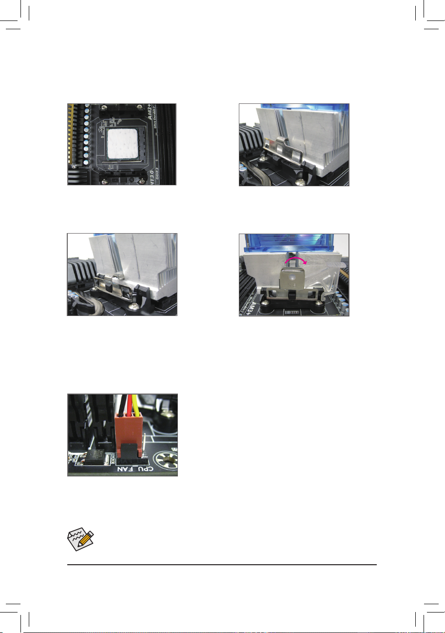
1-3-2 Installing the CPU Cooler
Follow the steps below to correctly install the CPU cooler on the CPU. (The following procedure uses the
GIGABYTE cooler as the example.)
Step 1:
Apply an even and thin layer of thermal grease
on the surface of the installed CPU.
Step 2:
Place the CPU cooler on the CPU.
Step 3:
Hook the CPU cooler clip to the mounting lug
on one side of the retention frame. On the other
side,push straight down on the the CPU cooler
clip to hook it to the mounting lug on the retention frame.
Step 4:
Turn the cam handle from the left side to the
right side (as the picture above shows) to lock
into place. (Refer to your CPU cooler installation
manual for instructions on installing the cooler.)
Step 5:
Finally, attach the power connector of the CPU cooler to the CPU
fan header (CPU_FAN) on the motherboard.
Use extreme care when removing the CPU cooler because the thermal grease/tape between the
CPU cooler and CPU may adhere to the CPU. Inadequately removing the CPU cooler may damage
the CPU.
Page 16
Hardware Installation - 16 -
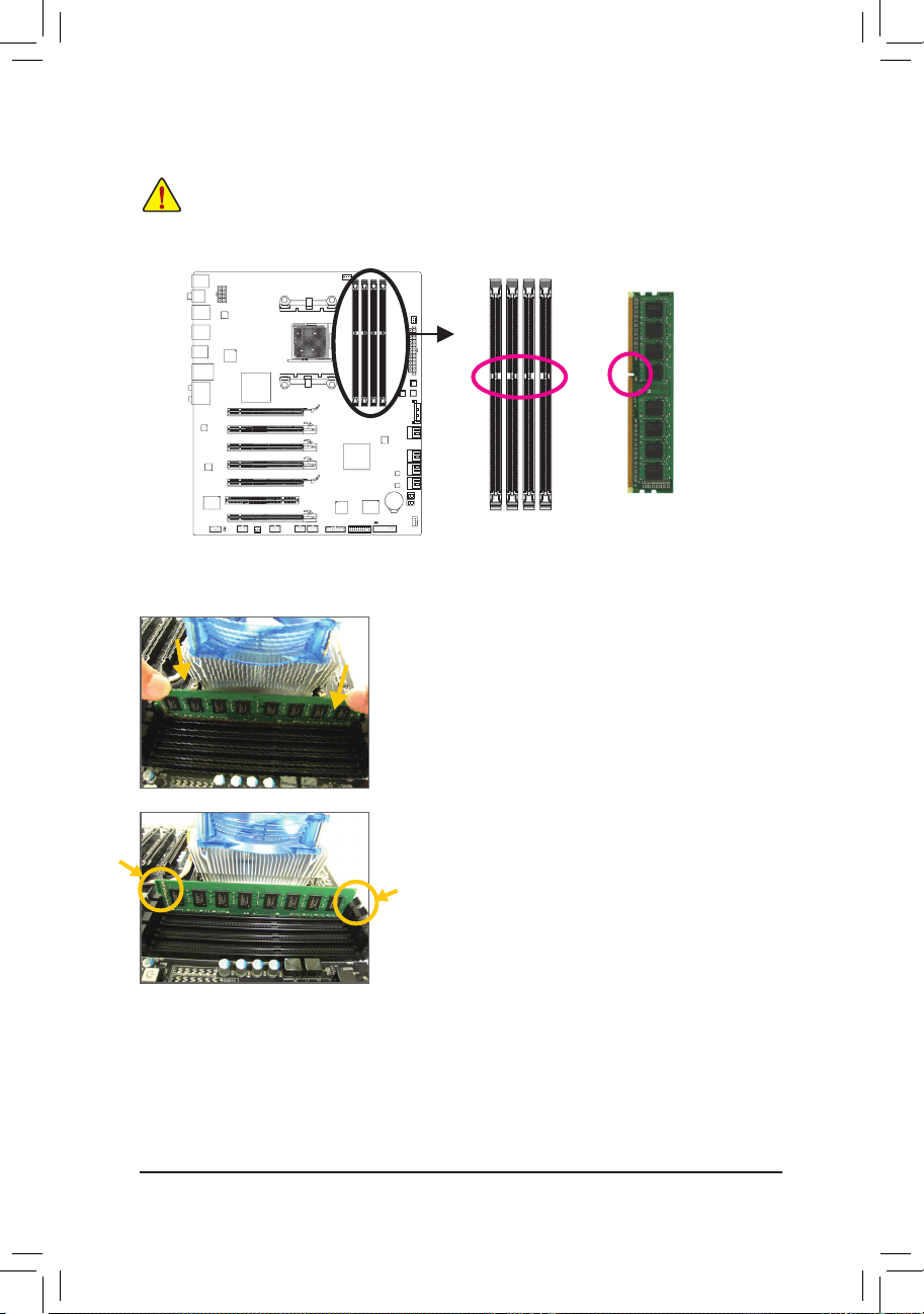
1-4 Installing the Memory
Read the following guidelines before you begin to install the memory:
• Make sure that the motherboard supports the memory. It is recommended that memory of the
same capacity, brand, speed, and chips be used.
(Go to GIGABYTE's website for the latest supported memory speeds and memory modules.)
• Always turn off the computer and unplug the power cord from the power outlet before installing
the memory to prevent hardware damage.
• Memory modules have a foolproof design. A memory module can be installed in only one direction. If you are unable to insert the memory, switch the direction.
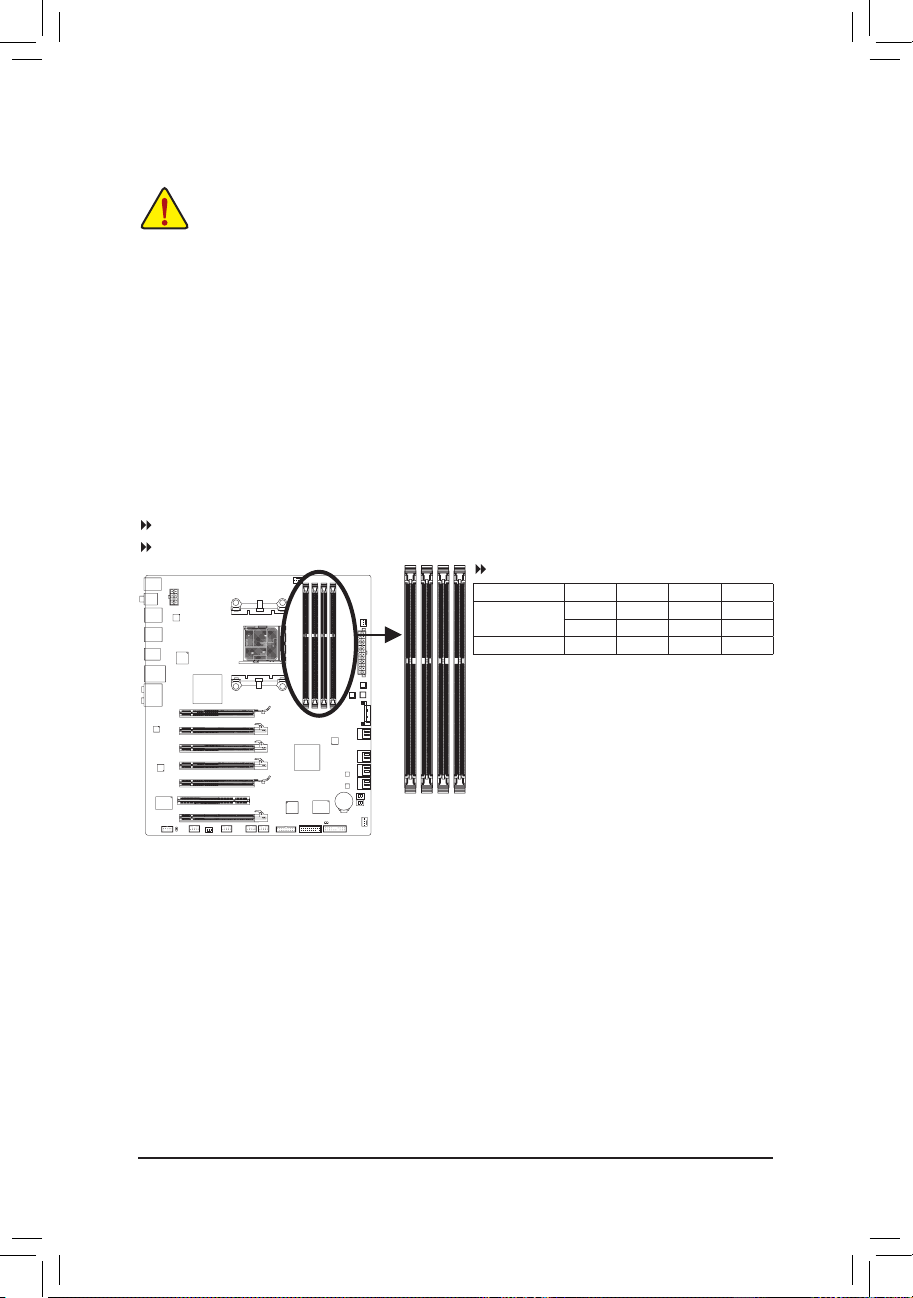
1-4-1 Dual Channel Memory Conguration
This motherboard provides four DDR3 memory sockets and supports Dual Channel Technology. After the
memory is installed, the BIOS will automatically detect the specications and capacity of the memory. Enabling Dual Channel memory mode will double the original memory bandwidth.
The four DDR3 memory sockets are divided into two channels and each channel has two memory sockets as
following:
Channel 0: DDR3_2, DDR3_4
Channel 1: DDR3_1, DDR3_3
Dual Channel Memory Congurations Table
(SS=Single-Sided, DS=Double-Sided, "- -"=No Memory)
DDR3_4 DDR3_2 DDR3_3 DDR3_1
Two Modules - - DS/SS - - DS/SS
DS/SS - - DS/SS - -
Four Modules DS/SS DS/SS DS/SS DS/SS
Due to CPU limitations, read the following guidelines before installing the memory in Dual Channel mode.
1. Dual Channel mode cannot be enabled if only one DDR3 memory module is installed.
2. When enabling Dual Channel mode with two or four memory modules, it is recommended that
memory of the same capacity, brand, speed, and chips be used for optimum performance. For optimum performance, when enabling Dual Channel mode with two memory modules, we recommend
that you install them in the DDR3_1 and DDR3_2 sockets.
DDR3_4
DDR3_2
DDR3_3
DDR3_1
Page 17
- 17 - Hardware Installation
1-4-2 Installing a Memory
Notch
DDR3 DIMM
A DDR3 memory module has a notch, so it can only t in one direction. Follow the steps below to correctly
install your memory modules in the memory sockets.
Before installing a memory module, make sure to turn off the computer and unplug the power
cord from the power outlet to prevent damage to the memory module.
DDR3 and DDR2 DIMMs are not compatible to each other or DDR DIMMs. Be sure to install
DDR3 DIMMs on this motherboard.
Step 1:
Note the orientation of the memory module. Spread the retaining
clips at both ends of the memory socket. Place the memory module
on the socket. As indicated in the picture on the left, place your ngers on the top edge of the memory, push down on the memory and
insert it vertically into the memory socket.
Step 2:
The clips at both ends of the socket will snap into place when the
memory module is securely inserted.
Page 18
Hardware Installation - 18 -
1-5 Installing an Expansion Card
Read the following guidelines before you begin to install an expansion card:
• Make sure the motherboard supports the expansion card. Carefully read the manual that came
with your expansion card.
• Always turn off the computer and unplug the power cord from the power outlet before installing
an expansion card to prevent hardware damage.
Follow the steps below to correctly install your expansion card in the expansion slot.
1. Locate an expansion slot that supports your card. Remove the metal slot cover from the chassis back panel.
2. Align the card with the slot, and press down on the card until it is fully seated in the slot.
3. Make sure the metal contacts on the card are completely inserted into the slot.
4. Secure the card’s metal bracket to the chassis back panel with a screw.
5. After installing all expansion cards, replace the chassis cover(s).
6. Turn on your computer. If necessary, go to BIOS Setup to make any required BIOS changes for your
expansion card(s).
7. Install the driver provided with the expansion card in your operating system.
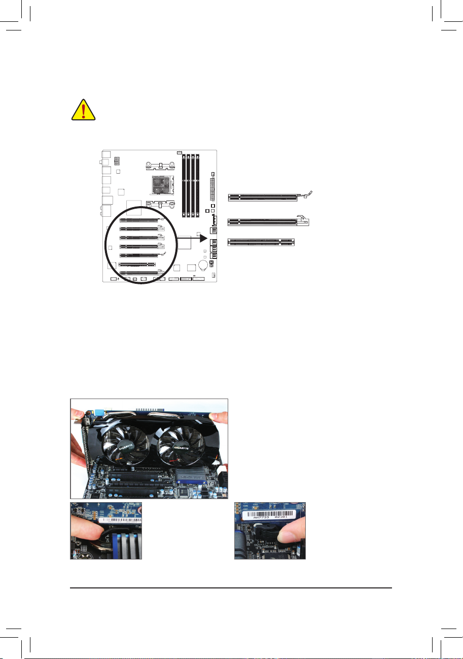
Example: Installing and Removing a PCI Express Graphics Card:
PCI Slot
PCI Express x16 Slot (PCIEX8_1/PCIEX8_2/PCIEX4_1/PCIEX4_2)
PCI Express x16 Slot (PCIEX16_1/PCIEX16_2)
• Installing a Graphics Card:
Gently push down on the top edge of the card until
it is fully inserted into the PCI Express slot. Make
sure the card is securely seated in the slot and
does not rock.
•
Re mo v in g t h e Ca r d
from the PCIEX16_1/
PCIEX16_2 Slot:
Gently push back on the
lever on the slot and then
lift the card straight out
from the slot.
•
Removing the Card from
the PCIEX8_1/PCIEX8_2/
PCIEX4_1/PCIEX4_2 Slot:
Press the latch at the end
of the PCI Express slot
to release the card and
then pull the card straight
up from the slot.
Page 19
- 19 - Hardware Installation
1-6 Setup of AMD CrossFireX™ Conguration
A. System Requirements
- The 2-Way CrossFireX technology currently support Windows 7, Vista, XP operating systems
- The 3-Way/4-Way CrossFireX technology currently support Windows 7 and Vista operating systems
- A CrossFireX-supported motherboard with two/three/four PCI Express x16 slots and correct driver
- Two/three/four CrossFireX-ready graphics cards of identical brand and chip and correct driver
( Current GPUs that support 3-Way/4-Way CrossFireX technology include the ATI Radeon HD 3800, HD 4800, and HD 5800 series
and AMD Radeon HD 6950, HD 6970 and HD 6990 series.)
- CrossFire bridge connectors
(Note 1)
-
A power supply with sufcient power is recommended (refer to the manual of your graphics cards for the power requirement)
(Note 2)
B. Connecting the Graphics Cards
Step 1:
Observe the steps in "1-5 Installing an Expansion Card" and install two/three/four graphics cards on the PCI Express x16
slots. The following table shows the recommended congurations with two/three/four cards.
Step 2:
Insert the CrossFire
bridge connectors
(Note 1)
in the CrossFireX gold edge connectors on top of the graphics cards.
Step 3:
Plug the display cable into the graphics card on the PCIEX16_1 slot.
Recommended 2/3/4-Way CrossFireX Congurations:
PCIEX16_1 PCIEX16_2 PCIEX8_1 PCIEX8_2 PCIEX4_1 PCIEX4_2
a
a
-- -- - - - -
a
a
a
-- - - - -
- -
a
a
a
- - - -
a
a
a
a
- - - -
2-Way
3-Way
4-Way
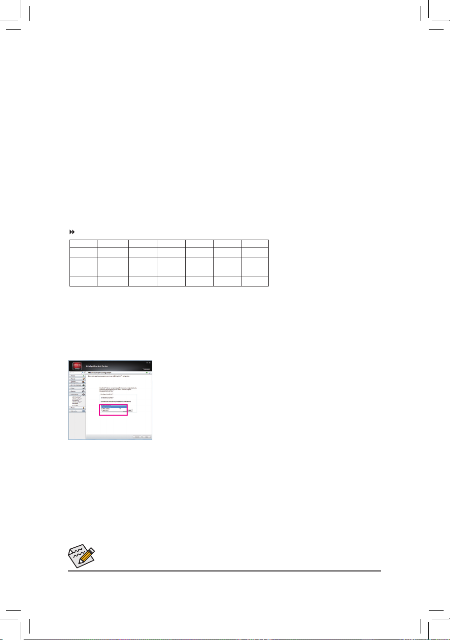
C. Conguring the Graphics Card Driver
After installing the graphics card driver in the operating system, go to the Catalyst Control Center. Browse to Performance\AMD CrossFireX Congurations and ensure the
Enable CrossFireX
™
check box is selected. Select the GPU combination you want to
use. (Available combination options are dependent on the number of graphics cards you
install.)
(Note 1) The bridge connectors may be needed or not depending on your graphics cards.
(Note 2) When two or more graphics cards are to be installed, we recommend that you connect the SATA power cable from
the power supply to the ATX4P connector to ensure system stability.
Procedure and driver screen for enabling CrossFireX technology may differ by graphics cards and driver version. Refer to the
manual that came with your graphics cards for more information about enabling CrossFireX technology.
Page 20
Hardware Installation - 20 -
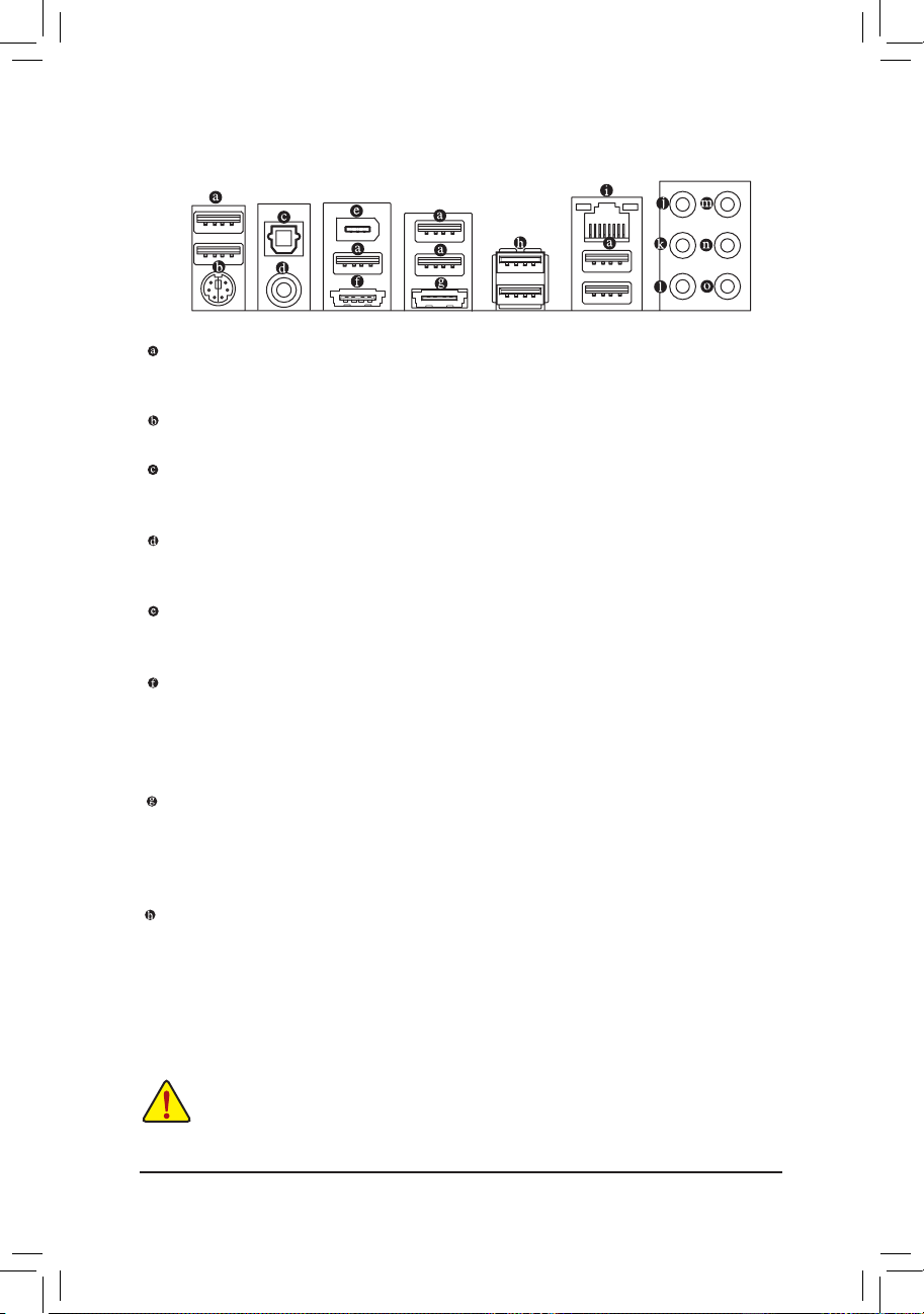
1-7 Back Panel Connectors
USB 2.0/1.1 Port
The USB port supports the USB 2.0/1.1 specication. Use this port for USB devices such as a USB keyboard/mouse, USB printer, USB ash drive and etc.
PS/2 Keyboard/Mouse Port
Use this port to connect a PS/2 mouse or keyboard.
Optical S/PDIF Out Connector
This connector provides digital audio out to an external audio system that supports digital optical audio.
Before using this feature, ensure that your audio system provides an optical digital audio in connector.
Coaxial S/PDIF Out Connector
This connector provides digital audio out to an external audio system that supports digital coaxial audio.
Before using this feature, ensure that your audio system provides a coaxial digital audio in connector.
IEEE 1394a Port
The IEEE 1394 port supports the IEEE 1394a specication, featuring high speed, high bandwidth and
hotplug capabilities. Use this port for an IEEE 1394a device.
eSATA/USB Combo Connector
This connector supports SATA 6Gb/s and USB 2.0/1.1 specication. Use the port to connect an external
SATA device or a SATA port multiplier. The Marvell 88SE9172 chip supports RAID function. Refer to
Chapter 5, "Conguring SATA Hard Drive(s)," for instructions on conguring a RAID array. Or use this
port for USB devices such as a USB keyboard/mouse, USB printer, USB ash drive and etc.
eSATA 6Gb/s Connector
The eSATA 6Gb/s port conforms to SATA 6Gb/s standard and is compatible with SATA 3Gb/s and SATA
1.5Gb/s standard. Use the port to connect an external SATA device or a SATA port multiplier. The Mar-
vell 88SE9172 chip supports RAID function. Refer to Chapter 5, "Conguring SATA Hard Drive(s)," for
instructions on conguring a RAID array.
USB 3.0/2.0 Port
The USB 3.0 port supports the USB 3.0 specication and is compatible to the USB 2.0/1.1 specication.
Use this port for USB devices such as a USB keyboard/mouse, USB printer, USB ash drive and etc.
When removing the cable connected to a back panel connector, rst remove the cable from your •
device and then remove it from the motherboard.
When removing the cable, pull it straight out from the connector. Do not rock it side to side to •
prevent an electrical short inside the cable connector.
Page 21
- 21 - Hardware Installation
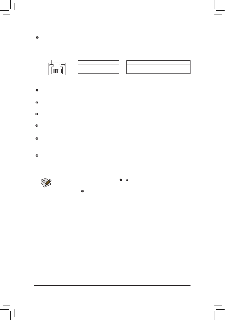
RJ-45 LAN Port
The Gigabit Ethernet LAN port provides Internet connection at up to 1 Gbps data rate. The following
escribes the states of the LAN port LEDs.
Activity LED
Connection/
Speed LED
LAN Port
Activity LED:Connection/Speed LED:
State Description
Orange 1 Gb ps data rate
Green 100 Mb ps data rate
Off 10 Mbps data rate
State Description
Blinking Dat a transmissi on or receivin g is occurring
Off No data tr ansmission o r receiving is oc curring
In addition to the default speakers settings, the ~ audio jacks can be recongured to perform
different functions via the audio software. Only microphones still MUST be connected to the
default Mic in jack (
). Refer to the instructions on setting up a 2/4/5.1/7.1-channel audio con-
guration in Chapter 5, "Conguring 2/4/5.1/7.1-Channel Audio."
Center/Subwoofer Speaker Out Jack (Orange)
Use this audio jack to connect center/subwoofer speakers in a 5.1/7.1-channel audio conguration.
Rear Speaker Out Jack (Black)
Use this audio jack to connect rear speakers in a 7-channel audio conguration.
Side Speaker Out Jack (Gray)
Use this audio jack to connect side speakers in a 4/5.1/7.1-channel audio conguration.
Line In Jack (Blue)
The default line in jack. Use this audio jack for line in devices such as an optical drive, walkman, etc.
Line Out Jack (Green)
The default line out jack. Use this audio jack for a headphone or 2-channel speaker. This jack can be
used to connect front speakers in a 4/5.1/7.1-channel audio conguration.
Mic In Jack (Pink)
The default Mic in jack. Microphones must be connected to this jack.
Page 22
Hardware Installation - 22 -
1-8 Onboard Buttons
This motherboard has 3 quick buttons: power button, reset button and clearing CMOS button. The power
button and reset button allow users to quickly turn on/off or reset the computer in an open-case environment
when they want to change hardware components or conduct hardware testing. Use the clearing CMOS but-
ton to clear the CMOS values (e.g. date information and BIOS congurations) and reset the CMOS values to
factory defaults when needed.
PW_SW: Power button
RST_SW: Reset button
CMOS_SW: Clearing CMOS button
• Always turn off your computer and unplug the power cord from the power outlet before clearing the CMOS values.
• After system restart, go to BIOS Setup to load factory defaults (select Load Optimized
Defaults) or manually congure the BIOS settings (refer to Chapter 2, "BIOS Setup," for BIOS
congurations).
Page 23
- 23 - Hardware Installation
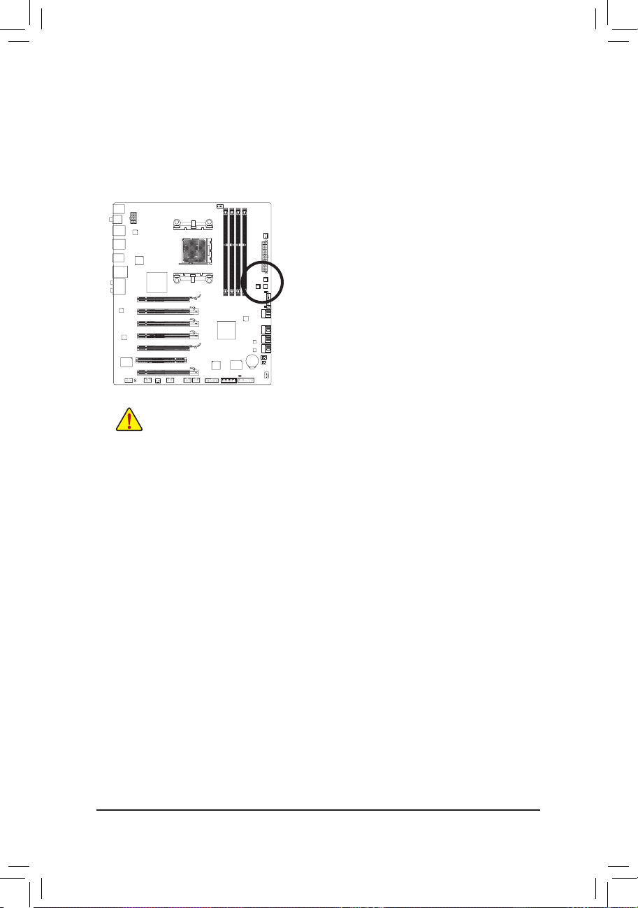
1-9 Internal Connectors
Read the following guidelines before connecting external devices:
• First make sure your devices are compliant with the connectors you wish to connect.
• Before installing the devices, be sure to turn off the devices and your computer. Unplug the
power cord from the power outlet to prevent damage to the devices.
• After installing the device and before turning on the computer, make sure the device cable has
been securely attached to the connector on the motherboard.
1) ATX_12V
2) ATX
3) ATX4P
4) CPU_FAN
5) SYS_FAN1/SYS_FAN2
6) PWR_FAN
7) SATA3_0/1/2/3/4/5
8) GSATA3_6/GSATA3_7
9) F_PANEL
10) F_AUDIO
11) SPDIF_O
12) F_USB1/F_USB2/F_USB3
13) F_USB30
14) F_1394
15) CLR_CMOS
16) BAT
17) TPM
4
2
1
8
3
7
16
5
91713125141110
6
15
Page 24
Hardware Installation - 24 -
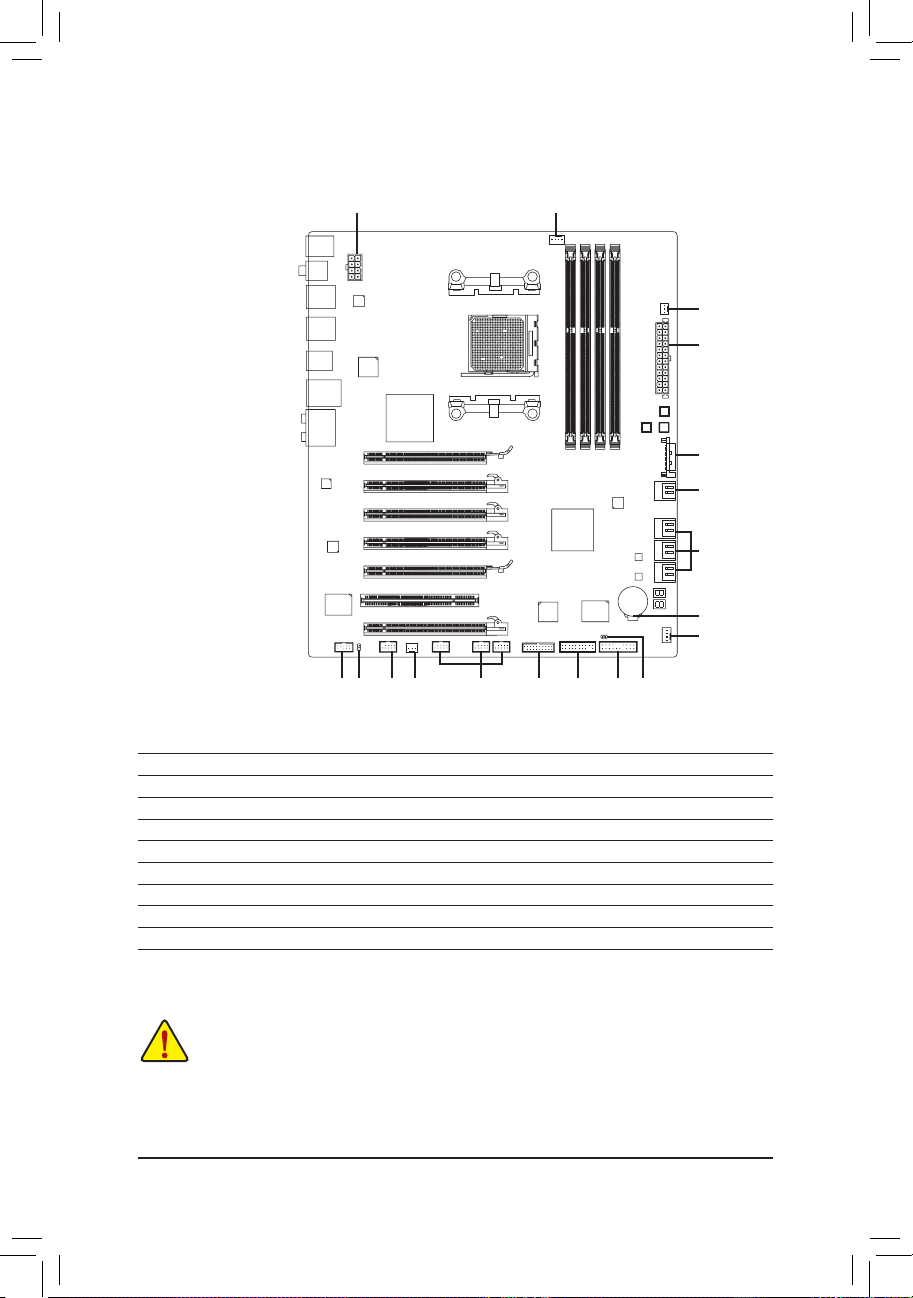
1/2) ATX_12V/ATX (2x4 12V Power Connector and 2x12 Main Power Connector)
With the use of the power connector, the power supply can supply enough stable power to all the com-
ponents on the motherboard. Before connecting the power connector, rst make sure the power supply
is turned off and all devices are properly installed. The power connector possesses a foolproof design.
Connect the power supply cable to the power connector in the correct orientation. The 12V power connector mainly supplies power to the CPU. If the 12V power connector is not connected, the computer will
not start.
To meet expansion requirements, it is recommended that a power supply that can withstand high
power consumption be used (500W or greater). If a power supply is used that does not provide
the required power, the result can lead to an unstable or unbootable system.
131
2412
ATX
ATX:
Pin No. Denition Pin No. Denition
1 3.3V 13 3.3V
2 3.3V 14 -12V
3 GND 15 GND
4 +5V 16 PS_ON (soft On/Off)
5 GND 17 GND
6 +5V 18 GND
7 GND 19 GND
8 Power Good 20 -5V
9 5VSB (stand by +5V) 21 +5V
10 +12V 22 +5V
11 +12V (Only for 2x12-pin ATX) 23 +5V (Only for 2x12-pin ATX)
12 3.3V (Only for 2x12-pin ATX) 24 GND (Only for 2x12-pin ATX)
ATX_12V
Pin No. Denition
1 GND (Only for 2x4-pin 12V)
2 GND (Only for 2x4-pin 12V)
3 GND
4 GND
5 +12V (Only for 2x4-pin 12V)
6 +12V (Only for 2x4-pin 12V)
7 +12V
8 +12V
ATX_12V
5
8
1
4
Page 25
- 25 - Hardware Installation
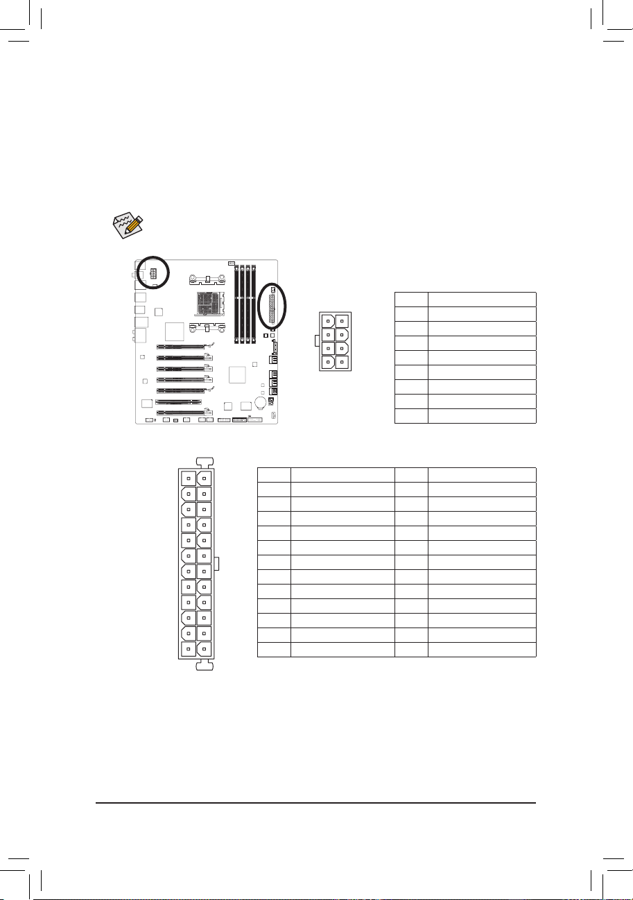
3) ATX4P (PCIe Power Connector)
The power connector provides auxiliary power to the onboard PCI Express x16 slots. When two or more
graphics cards are to be installed, we recommend that you connect the SATA power cable from
the power supply to the ATX4P connector to ensure system stability.
Pin No. Denition
1 NC
2 NC
3 NC
4 GND
5 GND
6 GND
7 VCC
8 VCC
9 VCC
10 GND
11 GND
12 GND
13 +12V
14 +12V
15 +12V
15
1
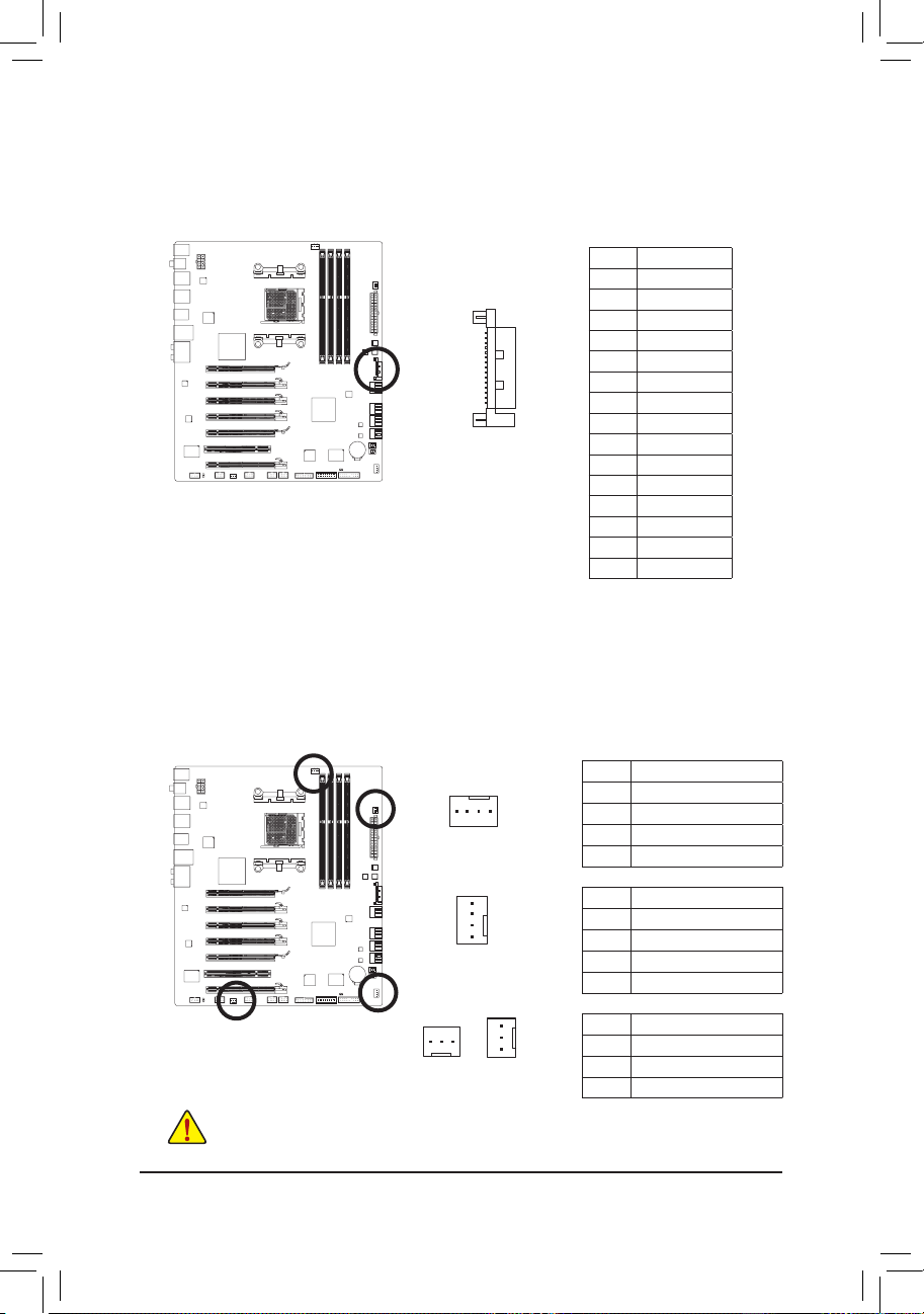
4/5/6) CPU_FAN/SYS_FAN1/SYS_FAN2/PWR_FAN (Fan Headers)
The motherboard has a 4-pin CPU fan header (CPU_FAN), a 3-pin (SYS_FAN2) and a 4-pin (SYS_FAN1)
system fan headers, and a 3-pin power fan header (PWR_FAN). Most fan headers possess a foolproof
insertion design. When connecting a fan cable, be sure to connect it in the correct orientation (the black
connector wire is the ground wire). The motherboard supports CPU fan speed control, which requires the
use of a CPU fan with fan speed control design. For optimum heat dissipation, it is recommended that a
system fan be installed inside the chassis.
CPU_FAN:
SYS_FAN1:
SYS_FAN2/PWR_FAN:
Pin No. Denition
1 GND
2 +12V /Speed Control
3 Sense
4 Speed Control
Pin No. Denition
1 GND
2 +12V /Speed Control
3 Sense
4 Reserve
Pin No. Denition
1 GND
2 +12V
3 Sense
Be sure to connect fan cables to the fan headers to prevent your CPU and system from overheating. Over- •
heating may result in damage to the CPU or the system may hang.
These fan headers are not conguration jumper blocks. Do not place a jumper cap on the headers.
•
1
CPU_FAN
SYS_FAN1
PWR_FAN
SYS_FAN2
1
1
1
Page 26
Hardware Installation - 26 -
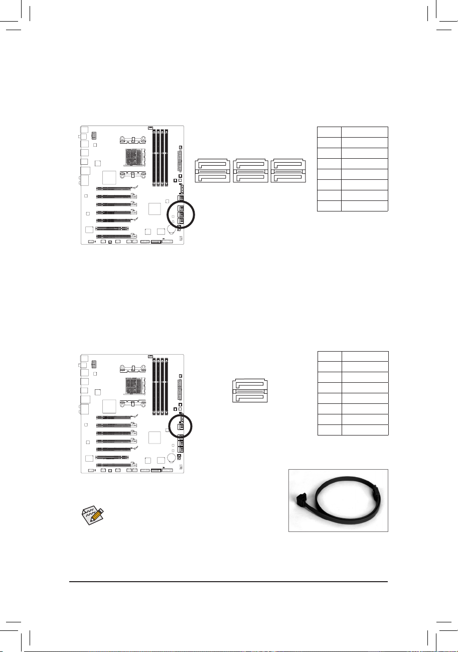
7) SATA3_0/1/2/3/4/5 (SATA 6Gb/s Connectors, Controlled by AMD SB950 South Bridge)
The SATA connectors conform to SATA 6Gb/s standard and are compatible with SATA 3Gb/s and SATA
1.5Gb/s standards. Each SATA connector supports a single SATA device. The AMD SB950 South Bridge
supports RAID 0, RAID 1, RAID 5, RAID 10, and JBOD. Refer to Chapter 5, "Conguring SATA Hard
Drive(s)," for instructions on conguring a RAID array.
• A RAID 0 or RAID 1 configuration requires at least two
hard drives. If more than two hard drives are to be used,
the total number of hard drives must be an even number.
• A RAID 5 conguration requires at least three hard drives.
(The total number of hard drives does not have to be an
even number.)
• A RAID 10 conguration requires four hard drives.
Please connect the L-shaped end of
th e SATA cable t o your SATA hard
drive.
Pin No. Denition
1 GND
2 TXP
3 TXN
4 GND
5 RXN
6 RXP
7 GND
7
7
G.QBOFM
G.QBOFM
SATA3_3SATA3_1
SATA3_2SATA3_0
1
1
G.QBOFM
SATA3_5
SATA3_4
8) GSATA3_6/7 (SATA 6Gb/s Connectors, Controlled by Marvell 88SE9172 Chip)
The SATA connectors conform to SATA 6Gb/s standard and are compatible with SATA 3Gb/s and SATA
1.5Gb/s standards. Each SATA connector supports a single SATA device. The Marvell 88SE9172 chip
supports RAID 0 and RAID 1. Refer to Chapter 5, "Conguring SATA Hard Drive(s)," for instructions on
conguring a RAID array.
Pin No. Denition
1 GND
2 TXP
3 TXN
4 GND
5 RXN
6 RXP
7 GND
G.QBOFM
GSATA3_6
GSATA3_7
1
1
7
7
Page 27
- 27 - Hardware Installation
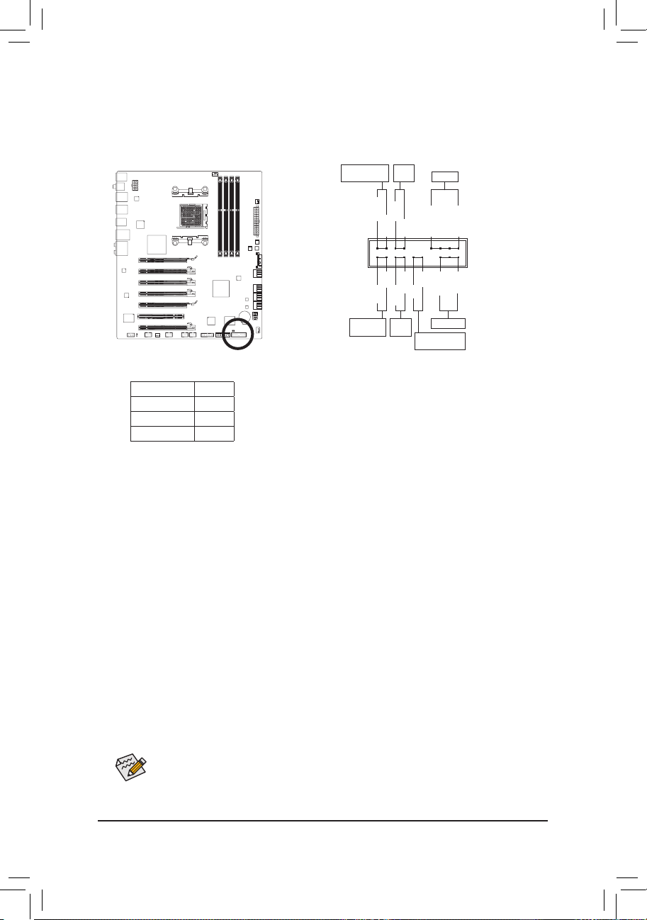
9) F_PANEL (Front Panel Header)
Connect the power switch, reset switch, speaker, chassis intrusion switch/sensor and system status
indicator on the chassis to this header according to the pin assignments below. Note the positive and
negative pins before connecting the cables.
The front panel design may differ by chassis. A front panel module mainly consists of power
switch, reset switch, power LED, hard drive activity LED, speaker and etc. When connecting your
chassis front panel module to this header, make sure the wire assignments and the pin assignments are matched correctly.
PW
• (Power Switch, Red):
Connects to the power switch on the chassis front panel. You may congure the way to turn off your
system using the power switch (refer to Chapter 2, "BIOS Setup," "Power Management Setup," for
more information).
SPEAK • (Speaker, Orange):
Connects to the speaker on the chassis front panel. The system reports system startup status by is-
suing a beep code. One single short beep will be heard if no problem is detected at system startup. If
a problem is detected, the BIOS may issue beeps in different patterns to indicate the problem. Refer
to Chapter 5, "Troubleshooting," for information about beep codes.
HD • (Hard Drive Activity LED, Blue)
Connects to the hard drive activity LED on the chassis front panel. The LED is on when the hard drive
is reading or writing data.
RES • (Reset Switch, Green):
Connects to the reset switch on the chassis front panel. Press the reset switch to restart the computer
if the computer freezes and fails to perform a normal restart.
CI • (Chassis Intrusion Header, Gray):
Connects to the chassis intrusion switch/sensor on the chassis that can detect if the chassis cover
has been removed. This function requires a chassis with a chassis intrusion switch/sensor.
MSG/PWR
• (Message/Power/Sleep LED, Yellow/Purple):
System Status LED
S0 On
S1 Blinking
S3/S4/S5 Off
Connects to the power status indicator on the chassis front panel. The LED
is on when the system is operating. The LED keeps blinking when the system is in S1 sleep state. The LED is off when the system is in S3/S4 sleep
state or powered off (S5).
Power LED
1
2
19
20
CI-
CI+
PWR-
PWR+
MSG-
PW-
SPEAK+
SPEAK-
MSG+
PW+
Message/Power/
Sleep LED
Speaker
Power
Switch
HD-
RES+
HD+
RES-
Hard Drive
Activity LED
Reset
Switch
Chassis Intrusion
Header
Page 28
Hardware Installation - 28 -
10) F_AUDIO (Front Panel Audio Header)
The front panel audio header supports Intel High Denition audio (HD) and AC'97 audio. You may connect
your chassis front panel audio module to this header. Make sure the wire assignments of the module connector match the pin assignments of the motherboard header. Incorrect connection between the module
connector and the motherboard header will make the device unable to work or even damage it.
• The front panel audio header supports HD audio by default. If your chassis provides an AC'97
front panel audio module, refer to the instructions on how to activate AC'97 functionality via
the audio software in Chapter 5, "Conguring 2/4/5.1/7.1-Channel Audio."
•
Audio signals will be present on both of the front and back panel audio connections simultane-
ously. If you want to mute the back panel audio (only supported when using an HD front panel
audio module), refer to Chapter 5, "Conguring 2/4/5.1/7.1-Channel Audio."
•
Some chassis provide a front panel audio module that has separated connectors on each wire
instead of a single plug. For information about connecting the front panel audio module that
has different wire assignments, please contact the chassis manufacturer.
For HD Front Panel Audio: For AC'97 Front Panel Audio:
Pin No. Denition
1 MIC2_L
2 GND
3 MIC2_R
4 -ACZ_DET
5 LINE2_R
6 GND
7 FAUDIO_JD
8 No Pin
9 LINE2_L
10 GND
Pin No. Denition
1 MIC
2 GND
3 MIC Power
4 NC
5 Line Out (R)
6 NC
7 NC
8 No Pin
9 Line Out (L)
10 NC
F_PANEL(NH) F_PANEL
(H61M-D2)
1
2
9
10
11) SPDIF_O (S/PDIF Out Header)
This header supports digital S/PDIF Out and connects a S/PDIF digital audio cable (provided by expan-
sion cards) for digital audio output from your motherboard to certain expansion cards like graphics cards
and sound cards. For example, some graphics cards may require you to use a S/PDIF digital audio cable
for digital audio output from your motherboard to your graphics card if you wish to connect an HDMI
display to the graphics card and have digital audio output from the HDMI display at the same time. For
information about connecting the S/PDIF digital audio cable, carefully read the manual for your expansion card.
Pin No. Denition
1 SPDIFO
2 GND
1
Page 29
- 29 - Hardware Installation
12) F_USB1/F_USB2/F_USB3 (USB 2.0/1.1 Headers)
The headers conform to USB 2.0/1.1 specication. Each USB header can provide two USB ports via an
optional USB bracket. For purchasing the optional USB bracket, please contact the local dealer.
Pin No. Denition
1 Power (5V)
2 Power (5V)
3 USB DX-
4 USB DY-
5 USB DX+
6 USB DY+
7 GND
8 GND
9 No Pin
10 NC
G.QBOFM
10
9
2
1
Do not plug the IEEE 1394 bracket (2x5-pin) cable into the USB 2.0/1.1 header. •
Prior to installing the USB bracket, be sure to turn off your computer and unplug the power •
cord from the power outlet to prevent damage to the USB bracket.
When the system is in S4/S5 mode, only the USB ports routed to the F_USB1 header can support the ON/OFF Charge function.
13) F_USB30 (USB 3.0/2.0 Header)
The header conforms to USB 3.0/2.0 specication. The USB header can provide two USB ports. For pur-
chasing the optional 3.5" front panel that provides two USB 3.0/2.0 ports, please contact the local dealer.
F_AUDIO(H)
F_PANEL(NH) F_PANEL
(H61M-D2)
20
1
Pin No. Denition Pin No. Denition
1 VBUS 11 D2+
2 SSRX1- 12 D2-
3 SSRX1+ 13 GND
4 GND 14 SSTX2+
5 SSTX1- 15 SSTX2-
6 SSTX1+ 16 GND
7 GND 17 SSRX2+
8 D1- 18 SSRX2-
9 D1+ 19 VBUS
10 NC 20 No Pin
11
10
Page 30
Hardware Installation - 30 -
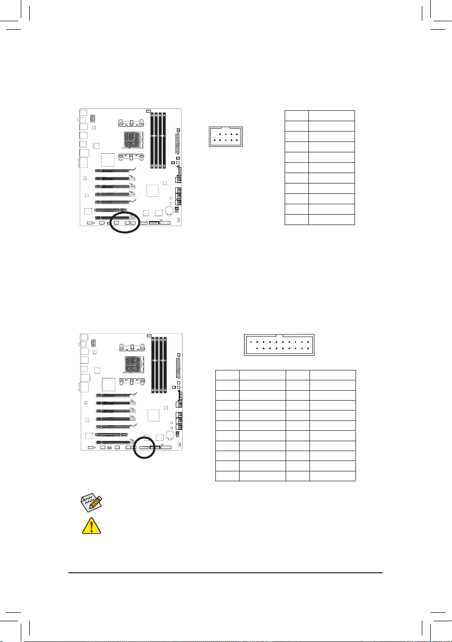
14) F_1394 (IEEE 1394a Header)
The header conforms to IEEE 1394a specication. The IEEE 1394a header can provide one IEEE 1394a
port via an optional IEEE 1394a bracket. For purchasing the optional IEEE 1394a bracket, please contact the local dealer.
•
Do not plug the USB bracket cable into the IEEE 1394a header.
• Prior to installing the IEEE 1394a bracket, be sure to turn off your computer and unplug the
power cord from the power outlet to prevent damage to the IEEE 1394a bracket.
• To connect an IEEE 1394a device, attach one end of the device cable to your computer and
then attach the other end of the cable to the IEEE 1394a device. Ensure that the cable is securely connected.
G.QBOFM
10
9
2
1
Pin No. Denition
1 TPA+
2 TPA-
3 GND-
4 GND
5 TPB+
6 TPB-
7 Power (12V)
8 Power (12V)
9 No Pin
10 GND
15) CLR_CMOS (Clearing CMOS Jumper)
Use this jumper to clear the CMOS values (e.g. date information and BIOS congurations) and reset
the CMOS values to factory defaults. To clear the CMOS values, place a jumper cap on the two pins to
temporarily short the two pins or use a metal object like a screwdriver to touch the two pins for a few
seconds.
Always turn off your computer and unplug the power cord from the power outlet before clear- •
ing the CMOS values.
After clearing the CMOS values and before turning on your computer, be sure to remove the •
jumper cap from the jumper. Failure to do so may cause damage to the motherboard.
After system restart, go to BIOS Setup to load factory defaults (select Load Optimized De- •
faults) or manually congure the BIOS settings (refer to Chapter 2, "BIOS Setup," for BIOS
congurations).
Open: Normal
Short: Clear CMOS Values
Page 31

- 31 - Hardware Installation
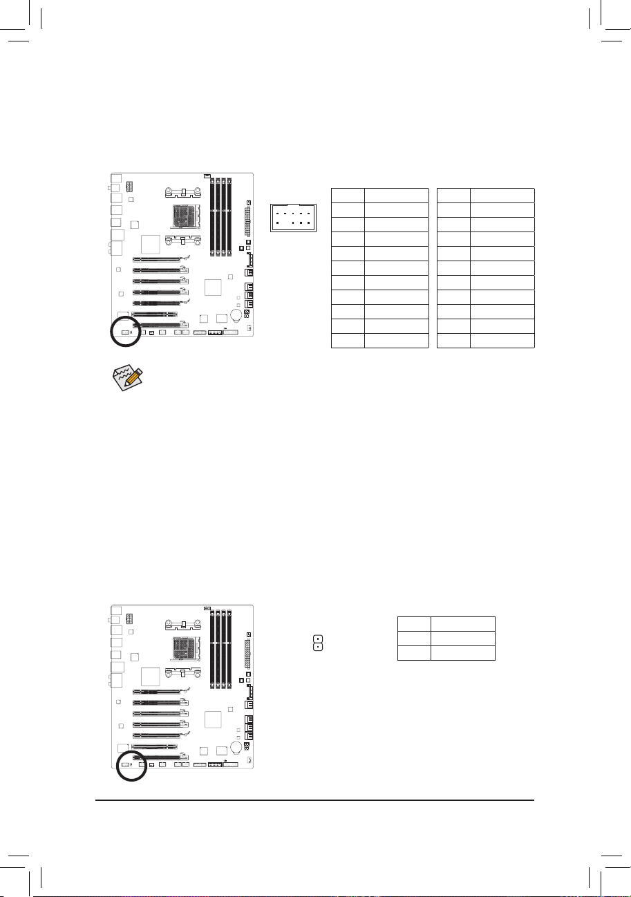
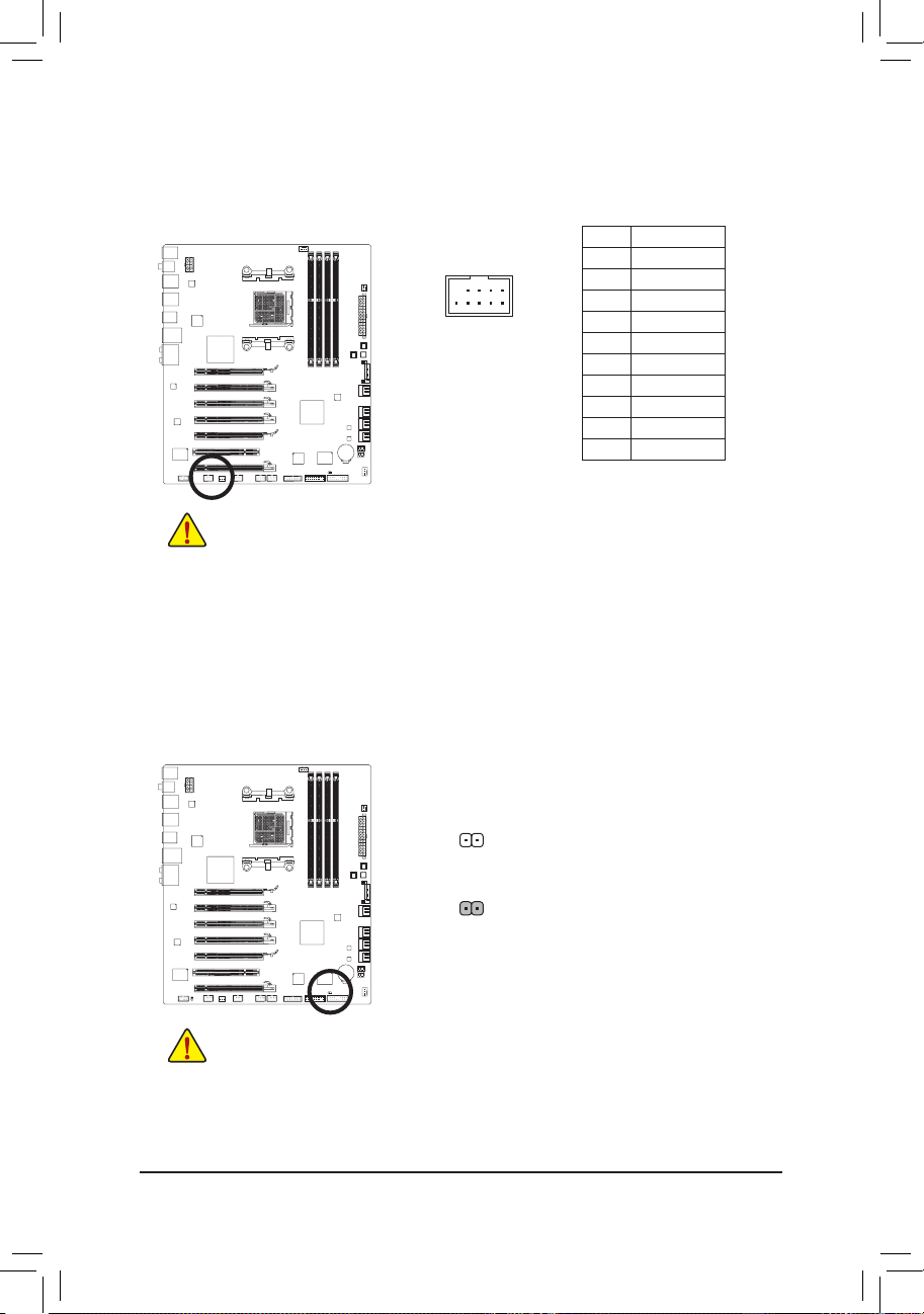
17) TPM (Trusted Platform Module Header)
You may connect a TPM (Trusted Platform Module) to this header.
20
19
2
1
F_AUDIO(H)
DB_PORT
F_PANEL(NH) F_PANEL
(H61M-D2)
Voltage measurement module(X58A-OC)
DIP
1 2 3
1
1
1
1
BIOS Switcher (X58A-OC)
PWM Switch (X58A-OC)
Pin No. Denition Pin No. Denition
1 LCLK 11 LAD0
2 GND 12 GND
3 LFRAME 13 NC
4 No Pin 14 ID
5 LRESET 15 SB3V
6 NC 16 SERIRQ
7 LAD3 17 GND
8 LAD2 18 NC
9 VCC3 19 NC
10 LAD1 20 SUSCLK
You may clear the CMOS values by removing the battery:
1. Turn off your computer and unplug the power cord.
2. Gently remove the battery from the battery holder and wait for one
minute. (Or use a metal object like a screwdriver to touch the positive
and negative terminals of the battery holder, making them short for 5
seconds.)
3. Replace the battery.
4. Plug in the power cord and restart your computer.
• Always turn off your computer and unplug the power cord before replacing the battery.
• Replace the battery with an equivalent one. Danger of explosion if the battery is replaced with
an incorrect model.
• Contact the place of purchase or local dealer if you are not able to replace the battery by yourself or uncertain about the battery model.
• When installing the battery, note the orientation of the positive side (+) and the negative side (-)
of the battery (the positive side should face up).
• Used batteries must be handled in accordance with local environmental regulations.
16) BAT (Battery)
The battery provides power to keep the values (such as BIOS congurations, date, and time information)
in the CMOS when the computer is turned off. Replace the battery when the battery voltage drops to a
low level, or the CMOS values may not be accurate or may be lost.
Page 32

Hardware Installation - 32 -
Page 33

- 33 - BIOS Setup
BIOS (Basic Input and Output System) records hardware parameters of the system in the CMOS on the
motherboard. Its major functions include conducting the Power-On Self-Test (POST) during system startup,
saving system parameters and loading operating system, etc. BIOS includes a BIOS Setup program that
allows the user to modify basic system conguration settings or to activate certain system features. When
the power is turned off, the battery on the motherboard supplies the necessary power to the CMOS to keep
the conguration values in the CMOS.
To access the BIOS Setup program, press the <Delete> key during the POST when the power is turned on.
To see more advanced BIOS Setup menu options, you can press <Ctrl> + <F1> in the main menu of the
BIOS Setup program.
To upgrade the BIOS, use either the GIGABYTE Q-Flash or @BIOS utility.
• Q-Flash allows the user to quickly and easily upgrade or back up BIOS without entering the operating
system.
• @BIOS is a Windows-based utility that searches and downloads the latest version of BIOS from the
Internet and updates the BIOS.
For instructions on using the Q-Flash and @BIOS utilities, refer to Chapter 4, "BIOS Update Utilities."
Chapter 2 BIOS Setup
• Because BIOS ashing is potentially risky, if you do not encounter problems using the current
version of BIOS, it is recommended that you not ash the BIOS. To ash the BIOS, do it with
caution. Inadequate BIOS ashing may result in system malfunction.
• BIOS will emit a beep code during the POST. Refer to Chapter 5, "Troubleshooting," for the beep
codes description.
• It is recommended that you not alter the default settings (unless you need to) to prevent system
instability or other unexpected results. Inadequately altering the settings may result in system's
failure to boot. If this occurs, try to clear the CMOS values and reset the board to default values.
(Refer to the "Load Optimized Defaults" section in this chapter or introductions of the battery/
clearing CMOS button/jumper in Chapter 1 for how to clear the CMOS values.)
Page 34

BIOS Setup - 34 -
2-1 Startup Screen
The following screens may appear when the computer boots.
A. The LOGO Screen (Default)
B. The POST Screen
Motherboard Model
BIOS Version
Function Keys
Function Keys:
<TAB>: POST SCREEN
Press the <Tab> key to show the BIOS POST screen. To show the BIOS POST screen at system start-
up, refer to the instructions on the Full Screen LOGO Show item on page 47.
<DEL>: BIOS SETUP\Q-FLASH
Press the <Delete> key to enter BIOS Setup or to access the Q-Flash utility in BIOS Setup.
<F9>: XPRESS RECOVERY2
If you have ever entered Xpress Recovery2 to back up hard drive data using the driver disk, the <F9>
key can be used for subsequent access to Xpress Recovery2 during the POST. For more information,
refer to Chapter 4, "Xpress Recovery2."
<F12>: BOOT MENU
Boot Menu allows you to set the rst boot device without entering BIOS Setup. In Boot Menu, use the up
arrow key <h> or the down arrow key <i> to select the rst boot device, then press <Enter> to accept.
To exit Boot Menu, press <Esc>. The system will directly boot from the device congured in Boot Menu.
Note: The setting in Boot Menu is effective for one time only. After system restart, the device boot order
will still be based on BIOS Setup settings. You can access Boot Menu again to change the rst boot device setting as needed.
<END>: Q-FLASH
Press the <End> key to access the Q-Flash utility directly without having to enter BIOS Setup rst.
Function Keys
Award Modular BIOS v6.00PG
Copyright (C) 1984-2011, Award Software, Inc.
GA-990FXA-UD7 F1a
.
.
.
.
<DEL>: BIOS Setup <F9>: XpressRecovery2 <F12>: Boot Menu <End>: Qflash
04/22/2011-RD990-SB950-7A66FG01C-00
Page 35

- 35 - BIOS Setup
2-2 The Main Menu
Once you enter the BIOS Setup program, the Main Menu (as shown below) appears on the screen. Use arrow keys to move among the items and press <Enter> to accept or enter a sub-menu.
(Sample BIOS Version: F1a)
Main Menu Help
The on-screen description of a highlighted setup option is displayed on the bottom line of the Main Menu.
Submenu Help
While in a submenu, press <F1> to display a help screen (General Help) of function keys available for the
menu. Press <Esc> to exit the help screen. Help for each item is in the Item Help block on the right side of
the submenu.
BIOS Setup Program Function Keys
<h><i><f><g> Move the selection bar to select an item
<Enter> Execute command or enter the submenu
<Esc> Main Menu: Exit the BIOS Setup program
Submenus: Exit current submenu
<Page Up> Increase the numeric value or make changes
<Page Down> Decrease the numeric value or make changes
<F1> Show descriptions of the function keys
<F2> Move cursor to the Item Help block on the right (submenus only)
<F5> Restore the previous BIOS settings for the current submenus
<F6> Load the Fail-Safe BIOS default settings for the current submenus
<F7> Load the Optimized BIOS default settings for the current submenus
<F8> Access the Q-Flash utility
<F9> Display system information
<F10> Save all the changes and exit the BIOS Setup program
<F11> Save CMOS to BIOS
<F12> Load CMOS from BIOS
• If you do not nd the settings you want in the Main Menu or a submenu, press <Ctrl>+<F1> to
access more advanced options.
• When the system is not stable as usual, select the Load Optimized Defaults item to set your
system to its defaults.
• The BIOS Setup menus described in this chapter are for reference only and may differ by BIOS
version.
CMOS Setup Utility-Copyright (C) 1984-2011 Award Software
Change CPU's Clock & Voltage
MB Intelligent Tweaker(M.I.T.)
Standard CMOS Features
Advanced BIOS Features
Integrated Peripherals
Power Management Setup
PC Health Status
Load Fail-Safe Defaults
Load Optimized Defaults
Set Supervisor Password
Set User Password
Save & Exit Setup
Exit Without Saving
ESC: Quit
higf
: Select Item F11: Save CMOS to BIOS
F8: Q-Flash F10: Save & Exit Setup F12: Load CMOS from BIOS
Page 36

BIOS Setup - 36 -
The Functions of the <F11> and <F12> keys (For the Main Menu Only)
F11: Save CMOS to BIOS
This function allows you to save the current BIOS settings to a prole. You can create up to 8 proles
(Prole 1-8) and name each prole. First enter the prole name (to erase the default prole name, use
the SPACE key) and then press <Enter> to complete.
F12: Load CMOS from BIOS
If your system becomes unstable and you have loaded the BIOS default settings, you can use this
function to load the BIOS settings from a prole created before, without the hassles of reconguring the
BIOS settings. First select the prole you wish to load, then press <Enter> to complete.
MB Intelligent Tweaker(M.I.T.)
Use this menu to congure the clock, frequency and voltages of your CPU, memory, etc.
Standard CMOS Features
Use this menu to congure the system time and date, hard drive types, and the type of errors that stop
the system boot, etc.
Advanced BIOS Features
Use this menu to congure the device boot order, advanced features available on the CPU, and the pri-
mary display adapter.
Integrated Peripherals
Use this menu to congure all peripheral devices, such as SATA, USB, integrated audio, and integrated
LAN, etc.
Power Management Setup
Use this menu to congure all the power-saving functions.
PC Health Status
Use this menu to see information about autodetected system/CPU temperature, system voltage and fan
speed, etc.
Load Fail-Safe Defaults
Fail-Safe defaults are factory settings for the most stable, minimal-performance system operations.
Load Optimized Defaults
Optimized defaults are factory settings for optimal-performance system operations.
Set Supervisor Password
Change, set, or disable password. It allows you to restrict access to the system and BIOS Setup.
A supervisor password allows you to make changes in BIOS Setup.
Set User Password
Change, set, or disable password. It allows you to restrict access to the system and BIOS Setup.
A user password only allows you to view the BIOS settings but not to make changes.
Save & Exit Setup
Save all the changes made in the BIOS Setup program to the CMOS and exit BIOS Setup. (Pressing
<F10> can also carry out this task.)
Exit Without Saving
Abandon all changes and the previous settings remain in effect. Pressing <Y> to the conrmation mes-
sage will exit BIOS Setup. (Pressing <Esc> can also carry out this task.)
Page 37

- 37 - BIOS Setup
2-3 MB Intelligent Tweaker(M.I.T.)
• Whether the system will work stably with the overclock/overvoltage settings you made is depen-
dent on your overall system congurations. Incorrectly doing overclock/overvoltage may result in
damage to CPU, chipset, or memory and reduce the useful life of these components. This page is
for advanced users only and we recommend you not to alter the default settings to prevent system
instability or other unexpected results. (Inadequately altering the settings may result in system's
failure to boot. If this occurs, clear the CMOS values and reset the board to default values.)
• When the System Voltage Optimized item blinks in red, it is recommended that you set the
System Voltage Control item to Auto to optimize the system voltage settings.
CMOS Setup Utility-Copyright (C) 1984-2011 Award Software
MB Intelligent Tweaker(M.I.T.)
CPU Clock Ratio [Auto]
CPU NorthBridge Freq. [Auto]
Core Performance Boost
(Note)
[Enabled]
CPB Ratio
(Note)
[Auto]
Turbo CPB
(Note)
[Disabled]
CPU Host Clock Control [Auto]
x CPU Frequency(MHz) 200
PCIE Clock(MHz) [Auto]
HT Link Width [Auto]
HT Link Frequency [Auto] 2000Mhz
Set Memory Clock [Auto]
x Memory Clock x6.66 1333Mhz
DRAMConguration [PressEnter]
********
System Voltage Optimized
********
System Voltage Control [Auto]
x CPU PLL Voltage Control Auto
x DRAM Voltage Control Auto
x DDR VT Voltage Control Auto
x NB Voltage Control Auto
higf
: Move Enter: Select +/-/PU/PD: Value F10: Save ESC: Exit F1: General Help
F5: Previous Values F6: Fail-Safe Defaults F7: Optimized Defaults
Item Help
Menu Level
CMOS Setup Utility-Copyright (C) 1984-2011 Award Software
MB Intelligent Tweaker(M.I.T.)
higf
: Move Enter: Select +/-/PU/PD: Value F10: Save ESC: Exit F1: General Help
F5: Previous Values F6: Fail-Safe Defaults F7: Optimized Defaults
Item Help
Menu Level
x HT Link Voltage Control Auto
x NB/PCIe/PLL Voltage Ctrl Auto
x CPU NB VID Control Auto
x CPU Voltage Control Auto
Normal CPU Vcore 1.3250V
(Note) This item is present only when you install a CPU that supports this feature.
Page 38

BIOS Setup - 38 -
CPU Clock Ratio
Allows you to alter the clock ratio for the installed CPU. The adjustable range is dependent on the CPU
being used.
CPU NorthBridge Freq.
Allows you to alter the North Bridge controller frequency for the installed CPU. The adjustable range is
dependent on the CPU being used.
Core Performance Boost
(Note)
Allows you to determine whether to enable the Core Performance Boost (CPB) technology, a CPU
performance-boost technology. (Default: Enabled)
CPB Ratio
(Note)
Allows you alter the ratio for the CPB. The adjustable range is dependent on the CPU being installed.
(Default: Auto)
Turbo CPB
(Note)
Allows you to determine whether to improve CPU performance. (Default: Disabled)
CPU Host Clock Control
Enables or disables the control of CPU host clock. Auto (default) allows the BIOS to automatically adjust
the CPU host frequency. Manual allows the CPU Frequency (MHz) item below to be congurable.
Note: If your system fails to boot after overclocking, please wait for 20 seconds to allow for automated
system reboot, or clear the CMOS values to reset the board to default values.
CPU Frequency(MHz)
Allows you to manually set the CPU host frequency. The adjustable range is from 200 MHz to 500 MHz.
This option is congurable only when CPU Host Clock Control is set to Manual. Important It is highly
recommended that the CPU frequency be set in accordance with the CPU specications.
PCIE Clock(MHz)
Allows you to manually set the PCIe clock frequency. The adjustable range is from 100 MHz to 150 MHz.
Auto sets the PCIe clock frequency to standard 100 MHz. (Default: Auto)
HT Link Width
Allows you to manually set the width for the HT Link between the CPU and chipset.
Auto BIOS will automatically adjust the HT Link Width. (Default)
8 bit Sets HT Link Width to 8 bit.
16 bit Sets HT Link Width to 16 bit.
HT Link Frequency
Allows you to manually set the frequency for the HT Link between the CPU and chipset.
Auto BIOS will automatically adjust the HT Link Frequency. (Default)
x1~x10 Sets HT Link Frequency to x1~x10 (200 MHz~2.0 GHz).
Set Memory Clock
Determines whether to manually set the memory clock. Auto lets BIOS automatically set the memory
clock as required. Manual allows the memory clock control item below to be congurable. (Default: Auto)
Memory Clock
This option is congurable only when Set Memory Clock is set to Manual.
X4.00 Sets Memory Clock to X4.00.
X5.33 Sets Memory Clock to X5.33.
X6.66 Sets Memory Clock to X6.66.
X8.00 Sets Memory Clock to X8.00.
(Note) This item is present only when you install a CPU that supports this feature.
Page 39

- 39 - BIOS Setup
DRAM Conguration
CMOS Setup Utility-Copyright (C) 1984-2011 Award Software
DRAMConguration
CPU Host Clock Control [Auto]
x CPU Frequency(MHz) 200
Set Memory Clock [Auto]
x Memory Clock x6.66 1333Mhz
DCTs Mode [Unganged]
DDR3 Timing Items [Auto] SPD Auto
x 1T/2T Command Timing Auto -- -x CAS# latency Auto 9T 9T
x RAS to CAS R/W Delay Auto 9T 9T
x Row Precharge Time Auto 9T 9T
x Minimum RAS Active Time Auto 24T 24T
x TwTr Command Delay Auto 5T 5T
x Trfc0 for DIMM1, DIMM3 Auto 110ns 110ns
x Trfc2 for DIMM2, DIMM4 Auto -- -x Write Recovery Time Auto 10T 10T
x Precharge Time Auto 5T 5T
x Row Cycle Time Auto 33T 33T
x RAS to RAS Delay Auto 4T 4T
**DCTs Drive Strength** DCT0 DCT1
higf
: Move Enter: Select +/-/PU/PD: Value F10: Save ESC: Exit F1: General Help
F5: Previous Values F6: Fail-Safe Defaults F7: Optimized Defaults
Item Help
Menu Level
CMOS Setup Utility-Copyright (C) 1984-2011 Award Software
DRAMConguration
higf
: Move Enter: Select +/-/PU/PD: Value F10: Save ESC: Exit F1: General Help
F5: Previous Values F6: Fail-Safe Defaults F7: Optimized Defaults
Item Help
Menu Level
ProcOdt(ohms) [Auto] 60 [Auto] 60
DQS Drive Strength [Auto] 1.0x [Auto] 1.0x
Data Drive Strength [Auto] 1.0x [Auto] 1.0x
MEMCLK Drive Strength [Auto] 1.25x [Auto] 1.25x
Addr/Cmd Drive Strength [Auto] 1.5x [Auto] 1.5x
CS/ODT Drive Strength [Auto] 1.5x [Auto] 1.5x
CKE Drive Strength [Auto] 1.5x [Auto] 1.5x
**DCTs Addr/Cmd Timing** DCT0 DCT1
Addr/Cmd Setup Time [Auto] 1T [Auto] 1/2T
Addr/Cmd Fine Delay [Auto] 22/64 [Auto] 0/64
CS/ODT Setup Time [Auto] 1/2T [Auto] 1/2T
CS/ODT Fine Delay [Auto] 0/64 [Auto] 0/64
CKE Setup Time [Auto] 1/2T [Auto] 1/2T
CKE Fine Delay [Auto] 0/64 [Auto] 0/64
Channel Interleaving [Enabled]
Bank Interleaving [Enabled]
CMOS Setup Utility-Copyright (C) 1984-2011 Award Software
DRAMConguration
higf
: Move Enter: Select +/-/PU/PD: Value F10: Save ESC: Exit F1: General Help
F5: Previous Values F6: Fail-Safe Defaults F7: Optimized Defaults
Item Help
Menu Level
DQS Training Control [Skip DQS]
CKE Power Down Mode [Disabled]
Memclock tri-stating [Disabled]
Page 40

BIOS Setup - 40 -
CPU Host Clock Control, CPU Frequency (MHz), Set Memory Clock, Memory Clock
The settings under the four items above are synchronous to those under the same items on the MB In telligent Tweaker(M.I.T.) main menu.
DCTs Mode
Allows you to set memory control mode.
Ganged Sets memory control mode to single dual-channel.
Unganged Sets memory control mode to two single-channel. (Default)
DDR3 Timing Items
Manual allows all DDR3 Timing items below to be congurable.
Options are: Auto (default), Manual.
1T/2T Command Timing
Options are: Auto (default), 1T, 2T.
CAS# latency
Options are: Auto (default), 4T~12T.
RAS to CAS R/W Delay
Options are: Auto (default), 5T~12T.
Row Precharge Time
Options are: Auto (default), 5T~12T.
Minimum RAS Active Time
Options are: Auto (default), 15T~30T.
TwTr Command Delay
Options are: Auto (default), 4T~7T.
Trfc0 for DIMM1, DIMM3
Options are: Auto (default), 90ns, 110ns, 160ns, 300ns, 350ns.
Trfc2 for DIMM2, DIMM4
Options are: Auto (default), 90ns, 110ns, 160ns, 300ns, 350ns.
Write Recovery Time
Options are: Auto (default), 5T~8T, 10T, 12T.
Precharge Time
Options are: Auto (default), 4T~7T.
Row Cycle Time
Options are: Auto (default), 11T~42T.
RAS to RAS Delay
Options are: Auto (default), 4T~7T.
**
DCTs Drive Strength
**
ProcOdt(ohms)
Options are: Auto (default), 240, 120, 60.
DQS Drive Strength
Options are: Auto (default), 0.75x, 1.0x, 1.25x, 1.5x.
Page 41

- 41 - BIOS Setup
Data Drive Strength
Options are: Auto (default), 0.75x, 1.0x, 1.25x, 1.5x.
MEMCLK Drive Strength
Options are: Auto (default), 0.75x, 1.0x, 1.25x, 1.5x.
Addr/Cmd Drive Strength
Options are: Auto (default), 1.0x, 1.25x, 1.5x, 2.0x.
CS/ODT Drive Strength
Options are: Auto (default), 1.0x, 1.25x, 1.5x, 2.0x.
CKE Drive Strength
Options are: Auto (default), 1.0x, 1.25x, 1.5x, 2.0x.
**
DCTs Addr/Cmd Timing
**
Addr/Cmd Setup Time
Options are: Auto (default), 1/2T, 1T.
Addr/Cmd Fine Delay
Options are: Auto (default)
, 0/64~31/64.
CS/ODT Setup Time
Options are: Auto (default), 1/2T, 1T.
CS/ODT Fine Delay
Options are: Auto (default)
, 0/64~31/64.
CKE Setup Time
Options are: Auto (default), 1/2T, 1T.
CKE Fine Delay
Options are: Auto (default)
, 0/64~31/64.
Channel Interleaving
Enables or disables memory channel interleaving. Enabled allows the system to simultaneously access
different channels of the memory to increase memory performance and stability. (Default: Enabled)
Bank Interleaving
Enables or disables memory bank interleaving. Enabled allows the system to simultaneously access dif-
ferent banks of the memory to increase memory performance and stability. (Default: Enabled)
DQS Training Control
Enables or disables memory DQS training each time the system restarts. (Default: Skip DQS)
CKE Power Down Mode
Determines whether to set the memory to power down mode when the CKE pin is closed. (Default: Dis-
abled)
Memclock tri-stating
Determines whether to enable memory clock tri-stating in CPU C3 or Alt VID mode. (Default: Disabled)
Page 42

BIOS Setup - 42 -
********
System Voltage Optimized
********
System Voltage Control
Determines whether to manually set the system voltages. Auto lets the BIOS automatically set the
system voltages as required. Manual allows all voltage control items below to be congurable. (Default:
Auto)
CPU PLL Voltage Control
Allows you to set the CPU PLL voltage.
Normal Supplies the CPU PLL voltage as required. (Default)
2.025V ~ 3.135V The adjustable range is from 2.025V to 3.135V.
Note: Increasing CPU voltage may result in damage to your CPU or reduce the useful life of the CPU.
DRAM Voltage Control
Allows you to set memory voltage.
Normal Supplies the memory voltage as required. (Default)
1.025V ~ 2.135V The adjustable range is from 1.025V to 2.135V.
Note: Increasing memory voltage may result in damage to the memory or reduce the useful life of the
memory.
DDR VTT Voltage Control
Allows you to set the DDR VTT voltage.
Normal Supplies the DDR VTT voltage as required. (Default)
0.515V ~ 1.145V The adjustable range is from 0.515V to 1.145V.
NB Voltage Control
Allows you to set the North Bridge voltage.
Normal Supplies the North Bridge voltage as required. (Default)
0.865V ~ 1.9750V The adjustable range is from 0.865V to 1.9750V.
HT Link Voltage Control
Allows you to set the HT Link voltage.
Normal Supplies the HT Link voltage as required. (Default)
0.725V ~ 1.835V The adjustable range is from 0.725V to 1.835V.
NB/PCIe/PLL Voltage Ctrl
Allows you to set the North Bridge PCIe PLL voltage.
Normal Supplies the North Bridge PCIe PLL voltage as required. (Default)
1.325V ~ 2.435V The adjustable range is from 1.325V to 2.435V.
CPU NB VID Control
Allows you to set the CPU North Bridge VID voltage. Auto sets the CPU North Bridge VID voltage as
required. The adjustable range is dependent on the CPU being installed. (Default: Normal)
Note: Increasing CPU voltage may result in damage to your CPU or reduce the useful life of the CPU.
CPU Voltage Control
Allows you to set the CPU voltage. Auto sets the CPU voltage as required. The adjustable range is de-
pendent on the CPU being installed. (Default: Normal)
Note: Increasing CPU voltage may result in damage to your CPU or reduce the useful life of the CPU.
Normal CPU Vcore
Displays the normal operating voltage of your CPU.
Page 43

- 43 - BIOS Setup
2-4 Standard CMOS Features
Date (mm:dd:yy)
Sets the system date. The date format is week (read-only), month, date and year. Select the desired eld
and use the up arrow or down arrow key to set the date.
Time (hh:mm:ss)
Sets the system time. For example, 1 p.m. is 13:0:0. Select the desired eld and use the up arrow or
down arrow key to set the time.
IDE Channel 0, 1 Master/Slave
IDE HDD Auto-Detection
Press <Enter> to autodetect the parameters of the SATA device on this channel.
IDE Channel 0, 1 Master/Slave
Congure your SATA devices by using one of the two methods below:
•Auto Lets the BIOS automatically detect SATA devices during the POST. (Default)
•None If no SATA devices are used, set this item to None so the system will skip
the detection of the device during the POST for faster system startup.
Access Mode Sets the hard drive access mode. Options are: Auto (default), CHS, LBA, Large.
IDE Channel 2, 4, 6 Master/Slave
IDE Auto-Detection
Press <Enter> to autodetect the parameters of the SATA device on this channel.
Extended IDE Drive
Congure your SATA devices by using one of the two methods below:
•Auto Lets the BIOS automatically detect SATA devices during the POST. (Default)
•None If no SATA devices are used, set this item to None so the system will skip
the detection of the device during the POST for faster system startup.
Access Mode Sets the hard drive access mode. Options are: Auto (default), Large.
Capacity Approximate capacity of the currently installed hard drive.
CMOS Setup Utility-Copyright (C) 1984-2011 Award Software
Standard CMOS Features
Date (mm:dd:yy) Wed, Mar 16 2011
Time (hh:mm:ss) 22:31:24
IDE Channel 0 Master [None]
IDE Channel 0 Slave [None]
IDE Channel 1 Master [None]
IDE Channel 1 Slave [None]
IDE Channel 2 Master [None]
IDE Channel 2 Slave [None]
IDE Channel 4 Master [None]
IDE Channel 4 Slave [None]
IDE Channel 6 Master [None]
IDE Channel 6 Slave [None]
Halt On [All, But Keyboard]
Base Memory 640K
Extended Memory 1022M
higf
: Move Enter: Select +/-/PU/PD: Value F10: Save ESC: Exit F1: General Help
F5: Previous Values F6: Fail-Safe Defaults F7: Optimized Defaults
Item Help
Menu Level
Page 44

BIOS Setup - 44 -
Halt On
Allows you to determine whether the system will stop for an error during the POST.
All Errors Whenever the BIOS detects a non-fatal error the system boot will stop.
No Errors The system boot will not stop for any error.
All, But Keyboard The system boot will not stop for a keyboard error but stop for all other errors.
(Default)
Memory
These elds are read-only and are determined by the BIOS POST.
Base Memory Also called conventional memory. Typically, 640 KB will be reserved for the
MS-DOS operating system.
Extended Memory The amount of extended memory.
Page 45

- 45 - BIOS Setup
2-5 Advanced BIOS Features
AMD C1E Support
Enables or disables the C1E CPU power-saving function in system halt state. When enabled, the power
consumption will be reduced during system halt state.
Auto If a CPU that supports hardware C1E is installed, the BIOS will automatically enable the
hardware C1E function. If not, the C1E function will be disabled. (Default)
Enabled If a CPU that supports hardware C1E is installed, the BIOS will automatically enable the
hardware C1E function. If not, the BIOS will enable the software C1E function.
Disabled Disables the C1E function.
CMOS Setup Utility-Copyright (C) 1984-2011 Award Software
Advanced BIOS Features
AMD C1E Support [Auto]
Virtualization [Disabled]
AMD K8 Cool&Quiet control [Auto]
CPU Unlock
(Note)
[Disabled]
CPU core Control [Auto]
x CPU core 0 Enabled
x CPU core 1 Enabled
x CPU core 2
(Note)
Enabled
x CPU core 3
(Note)
Enabled
x CPU core 4
(Note)
Enabled
x CPU core 5
(Note)
Enabled
Hard Disk Boot Priority [Press Enter]
EFI CD/DVD Boot Option [Auto]
First Boot Device [Hard Disk]
Second Boot Device [CDROM]
Third Boot Device [USB-HDD]
Password Check [Setup]
HDD S.M.A.R.T. Capability [Disabled]
Away Mode [Disabled]
higf
: Move Enter: Select +/-/PU/PD: Value F10: Save ESC: Exit F1: General Help
F5: Previous Values F6: Fail-Safe Defaults F7: Optimized Defaults
Item Help
Menu Level
CMOS Setup Utility-Copyright (C) 1984-2011 Award Software
Advanced BIOS Features
higf
: Move Enter: Select +/-/PU/PD: Value F10: Save ESC: Exit F1: General Help
F5: Previous Values F6: Fail-Safe Defaults F7: Optimized Defaults
Item Help
Menu Level
Full Screen LOGO Show [Enabled]
IOMMU support [Disabled]
Init Display First [PCI Slot]
(Note) This item is present only when you install a CPU that supports this feature.
Page 46

BIOS Setup - 46 -
Virtualization
Virtualization allows a platform to run multiple operating systems and applications in independent parti-
tions. With virtualization, one computer system can function as multiple virtual systems.
(Default: Disabled)
AMD K8 Cool&Quiet control
Auto Lets the AMD Cool'n'Quiet driver dynamically adjust the CPU clock and VID to re-
duce heat output from your computer and its power consumption. (Default)
Disabled Disables this function.
CPU Unlock
(Note)
Allows you to determine whether unlock hidden CPU cores. (Default: Disabled)
CPU core Control
Allows you to determine whether to manually enable/disable CPU Core 1/2/3/4/5.
Auto Lets the BIOS to enable all CPU cores (number of cores available depends on the
CPU being used). (Default)
Manual Allows you to individually enable/disable CPU Core 1/2/3/4/5.
CPU core 0
This setting is xed. CPU Core 0 is always enabled.
CPU core 1, 2/3/4/5
(Note)
Enables or disables CPU Core 1/2/3/4/5. (Default: Enabled)
Hard Disk Boot Priority
Species the sequence of loading the operating system from the installed hard drives. Use the up or
down arrow key to select a hard drive, then press the plus key <+> (or <PageUp>) or the minus key <-> (or
<PageDown>) to move it up or down on the list. Press <Esc> to exit this menu when nished.
EFI CD/DVD Boot Option
Set this item to EFI if you want to install the operating system to a hard drive larger than 2.2 TB. Make
sure the operating system to be installed supports booting from a GPT partition, such as Windows 7 64-
bit and Windows Server 2003 64-bit. Auto lets the BIOS automatically congure this setting depending
on the hard drive you install. (Default: Auto)
First/Second/Third Boot Device
Species the boot order from the available devices. Use the up or down arrow key to select a device
and press <Enter> to accept. Options are: LS120, Hard Disk, CDROM, ZIP, USB-FDD, USB-ZIP, USB-
CDROM, USB-HDD, Legacy LAN, Disabled.
Password Check
Species whether a password is required every time the system boots, or only when you enter BIOS
Setup. After conguring this item, set the password(s) under the Set Supervisor/User Password item in
the BIOS Main Menu.
Setup A password is only required for entering the BIOS Setup program. (Default)
System A password is required for booting the system and for entering the BIOS Setup
program.
(Note) This item is present only when you install a CPU that supports this feature.
Page 47

- 47 - BIOS Setup
HDD S.M.A.R.T. Capability
Enables or disables the S.M.A.R.T. (Self Monitoring and Reporting Technology) capability of your hard
drive. This feature allows your system to report read/write errors of the hard drive and to issue warnings
when a third party hardware monitor utility is installed. (Default: Disabled)
Away Mode
Enables or disables Away Mode in Windows XP Media Center operating system. Away Mode allows the
system to silently perform unattended tasks while in a low-power mode that appears off.
(Default: Disabled)
Full Screen LOGO Show
Allows you to determine whether to display the GIGABYTE Logo at system startup. Disabled displays
normal POST message. (Default: Enabled)
IOMMU support
Enables or disables AMD IOMMU support. (Default: Disabled)
Init Display First
Species the rst initiation of the monitor display from the installed PCI graphics card or PCI Express
graphics card.
PCI Slot Sets the PCI graphics card as the rst display. (Default)
PEG Sets the PCI Express graphics card on the PCIEX16_1 slot as the rst display.
PEG1 Sets the PCI Express graphics card on the PCIEX8_1 slot as the rst display.
PEG2 Sets the PCI Express graphics card on the PCIEX16_2 slot as the rst display.
PEG3 Sets the PCI Express graphics card on the PCIEX8_2 slot as the rst display.
PEG4 Sets the PCI Express graphics card on the PCIEX4_2 slot as the rst display.
PEG5 Sets the PCI Express graphics card on the PCIEX4_1 slot as the rst display.
Page 48

BIOS Setup - 48 -
2-6 Integrated Peripherals
CMOS Setup Utility-Copyright (C) 1984-2011 Award Software
Integrated Peripherals
OnChip SATA Controller [Enabled]
OnChip SATA Type [Native IDE]
x OnChip SATA Port4/5 Type IDE
x OnChip SATA RAID5 Support Enabled
OnChip SATA3.0 Support [Enabled]
x OnChip SATA Port as ESP Press Enter
F_USB30 Controller [Enabled]
eSATA3 Controller [Enabled]
eSATA3 Ctrl Mode [IDE]
GSATA3 Controller [Enabled]
GSATA3 Ctrl Mode [IDE]
Onboard PCIE Devices [Press Enter]
Onboard Audio Function [Enabled]
Onboard 1394 Function [Enabled]
R_USB30 Controller [Enabled]
USB Controllers [Enabled]
USB Legacy Function [Enabled]
USB Storage Function [Enabled]
higf
: Move Enter: Select +/-/PU/PD: Value F10: Save ESC: Exit F1: General Help
F5: Previous Values F6: Fail-Safe Defaults F7: Optimized Defaults
Item Help
Menu Level
Page 49

- 49 - BIOS Setup
OnChip SATA Port as ESP
CMOS Setup Utility-Copyright (C) 1984-2011 Award Software
OnChip SATA Port as ESP
Port0 as ESP [Disabled]
Port1 as ESP [Disabled]
Port2 as ESP [Disabled]
Port3 as ESP [Disabled]
Port4 as ESP [Disabled]
Port5 as ESP [Disabled]
higf
: Move Enter: Select +/-/PU/PD: Value F10: Save ESC: Exit F1: General Help
F5: Previous Values F6: Fail-Safe Defaults F7: Optimized Defaults
Item Help
Menu Level
Port0 as ESP/Port1 as ESP/Port2 as ESP/Port3 as ESP
This option is congurable only when OnChip SATA Type is set to AHCI. Enabled will speed up the hot
plug detection of the connected SATA device. (Default: Disabled)
Port4 as ESP/Port5 as ESP
This option is congurable only when OnChip SATA Type is set to AHCI and OnChip SATA Type
Port4/5 is set to as SATA Type. Enabled will speed up the hot plug detection of the connected SATA
device. (Default: Disabled)
F_USB30 Controller (Etron EJ168 USB controller, USB 3.0/2.0 ports routed to the on-
board F_USB30 header)
Enables or disables the Etron EJ168 USB controller. (Default: Enabled)
eSATA3 Controller (Marvell 88SE9172 chip, eSATA connectors on the back panel)
Enables or disables the SATA controller integrated in the Marvell 88SE9172 chip. (Default: Enabled)
eSATA3 Ctrl Mode (
Marvell 88SE9172
chip, eSATA connectors on the back panel)
Enables or disables RAID for the SATA controller integrated in the Marvell 88SE9172 chip or congures
the SATA controller to AHCI mode.
IDE Disables RAID for the SATA controller and congures the SATA controller to IDE
mode. (Default)
AHCI Congures the SATA controller to AHCI mode. Advanced Host Controller Interface
(AHCI) is an interface specication that allows the storage driver to enable advanced
Serial ATA features such as Native Command Queuing and hot plug.
RAID Enables RAID for the SATA controller.
GSATA3 Controller (Marvell 88SE9172 chip, GSATA3_6/7 connector)
Enables or disables the SATA controller integrated in the Marvell 88SE9172 chip. (Default: Enabled)
Page 50

BIOS Setup - 50 -
GSATA3 Ctrl Mode (
Marvell 88SE9172
chip,
GSATA3_6/7 connector
)
Enables or disables RAID for the SATA controller integrated in the Marvell 88SE9172 chip or congures
the SATA controller to AHCI mode.
IDE Disables RAID for the SATA controller and congures the SATA controller to IDE
mode. (Default)
AHCI Congures the SATA controller to AHCI mode. Advanced Host Controller Interface
(AHCI) is an interface specication that allows the storage driver to enable advanced
Serial ATA features such as Native Command Queuing and hot plug.
RAID Enables RAID for the SATA controller.
Onboard PCIE Devices
CMOS Setup Utility-Copyright (C) 1984-2011 Award Software
Onboard PCIE Devices
PrimaryDualSlotCong [Auto]
SecondaryDualSlotCong [Auto]
Onboard LAN Function [Enabled]
Onboard LAN Boot ROM [Disabled]
SMART LAN [Press Enter]
higf
: Move Enter: Select +/-/PU/PD: Value F10: Save ESC: Exit F1: General Help
F5: Previous Values F6: Fail-Safe Defaults F7: Optimized Defaults
Item Help
Menu Level
Primary Dual Slot Cong (PCIEX16_1 and PCIEX8_1 slots)
Species the operating bandwidth for the PCIEX16_1 and PCIEX8_1 slots.
Auto Lets the BIOS automatically congure this setting depending on the device being
installed. (Default)
X16 PCIEX16_1 operates at x16 and PCIEX8_1 becomes unavailable.
X8/X8 PCIEX16_1 and PCIEX8_1 operate at x8 respectively.
Secondary Dual Slot Cong (PCIEX16_2 and PCIEX8_2 slots)
Species the operating bandwidth for the PCIEX16_2 and PCIEX8_2 slots.
Auto Lets the BIOS automatically congure this setting depending on the device being
installed. (Default)
X16 PCIEX16_2 operates at x16 and PCIEX8_2 becomes unavailable.
X8/X8 PCIEX16_2 and PCIEX8_2 operate at x8 respectively.
Onboard LAN Function
Enables or disables the onboard LAN function. (Default: Enabled)
If you wish to install a 3rd party add-in network card instead of using the onboard LAN, set this item to
Disabled.
Onboard LAN Boot ROM
Allows you to decide whether to activate the boot ROM integrated with the onboard LAN chip.
(Default: Disabled)
Page 51

- 51 - BIOS Setup
This motherboard incorporates cable diagnostic feature designed to detect the status of the attached LAN
cable. This feature will detect cabling issue and report the approximate distance to the fault or short. Refer to
the following information for diagnosing your LAN cable:
When No LAN Cable Is Attached...
If no LAN cable is attached to the motherboard, the Status elds of all four pairs of wires will show Open
and the Length elds show 0m, as shown in the gure above.
When LAN Cable Is Functioning Normally...
If no cable problem is detected on the LAN cable connected to a Gigabit hub or a 10/100 Mbps hub, the
following message will appear:
SMART LAN (LAN Cable Diagnostic Function)
CMOS Setup Utility-Copyright (C) 1984-2011 Award Software
SMART LAN
Start detecting at Port.....
Part1-2 Status = Open / Length = 0m
Part3-6 Status = Open / Length = 0m
Part4-5 Status = Open / Length = 0m
Part7-8 Status = Open / Length = 0m
higf
: Move Enter: Select +/-/PU/PD: Value F10: Save ESC: Exit F1: General Help
F5: Previous Values F6: Fail-Safe Defaults F7: Optimized Defaults
Item Help
Menu Level
When a Cable Problem Occurs...
If a cable problem occurs on a specied pair of wires, the Status eld will show Short and then length
shown will be the approximate distance to the fault or short.
Example:
Part1-2 Status = Short / Length = 2m
Explanation: A fault or short might occur at about 2m on Part 1-2.
Note: Part 4-5 and Part 7-8 are not used in a 10/100 Mbps environment, so their Status elds will show
Open, and the length shown is the approximate length of the attached LAN cable.
Start detecting at Port.....
Link Detected --> 100Mbps
Cable Length= 30m
Link Detected Displays transmission speed.
Cable Length Displays the approximate length of the attached LAN cable.
Note: The Gigabit hub will only operate at a speed of 10/100 Mbps in MS-DOS mode; it will operate at a
normal speed of 10/100/1000 Mbps in Windows mode or when the LAN Boot ROM is activated.
Page 52

BIOS Setup - 52 -
Page 53

- 53 - BIOS Setup
ACPI Suspend Type
Species the ACPI sleep state when the system enters suspend.
S1(POS) Enables the system to enter the ACPI S1 (Power on Suspend) sleep state.
In S1 sleep state, the system appears suspended and stays in a low power mode.
The system can be resumed at any time.
S3(STR) Enables the system to enter the ACPI S3 (Suspend to RAM) sleep state (default).
In S3 sleep state, the system appears to be off and consumes less power than in
the S1 state. When signaled by a wake-up device or event, the system resumes to
its working state exactly where it was left off.
Soft-Off by Power button
Congures the way to turn off the computer in MS-DOS mode using the power button.
Instant-Off Press the power button and then the system will be turned off instantly. (Default)
Delay 4 Sec. Press and hold the power button for 4 seconds to turn off the system. If the power
button is pressed for less than 4 seconds, the system will enter suspend mode.
USB Wake Up from S3
Allows the system to be awakened from ACPI S3 sleep state by a wake-up signal from the installed USB
device. (Default: Enabled)
Modem Ring Resume
Allows the system to be awakened from an ACPI sleep state by a wake-up signal from a modem that
supports wake-up function. (Default: Disabled)
(Note) Supported on Windows 7/Vista operating system only.
2-7 Power Management Setup
CMOS Setup Utility-Copyright (C) 1984-2011 Award Software
Power Management Setup
ACPI Suspend Type [S3(STR)]
Soft-Off by Power button [Instant-off]
USB Wake Up from S3 [Enabled]
Modem Ring Resume [Disabled]
PME Event Wake Up [Enabled]
HPET Support
(Note)
[Enabled]
Power On By Mouse [Disabled]
Power On By Keyboard [Disabled]
x KB Power ON Password Enter
AC Back Function [Soft-Off]
Power-On by Alarm [Disabled]
x Date (of Month) Everyday
x Resume Time (hh:mm:ss) 0 : 0 : 0
ErP Support [Disabled]
higf
: Move Enter: Select +/-/PU/PD: Value F10: Save ESC: Exit F1: General Help
F5: Previous Values F6: Fail-Safe Defaults F7: Optimized Defaults
Item Help
Menu Level
Page 54

BIOS Setup - 54 -
(Note) Supported on Windows 7/Vista operating system only.
PME Event Wake Up
Allows the system to be awakened from an ACPI sleep state by a wake-up signal from a PCI or PCIe de-
vice. Note: To use this function, you need an ATX power supply providing at least 1A on the +5VSB lead.
(Default: Enabled)
HPET Support
(Note)
Enables or disables High Precision Event Timer (HPET) for Windows 7/Vista operating system.
(Default: Enabled)
Power On By Mouse
Allows the system to be turned on by a PS/2 mouse wake-up event.
Note: To use this function, you need an ATX power supply providing at least 1A on the +5VSB lead.
Disabled Disables this function. (Default)
Double Click Double click on left button on the PS/2 mouse to turn on the system.
Power On By Keyboard
Allows the system to be turned on by a PS/2 keyboard wake-up event.
Note: you need an ATX power supply providing at least 1A on the +5VSB lead.
Disabled Disables this function. (Default)
Password Set a password with 1~5 characters to turn on the system.
Any KEY Press any key on the keyboard to turn on the system.
Keyboard 98 Press POWER button on the Windows 98 keyboard to turn on the system.
KB Power ON Password
Set the password when Power On by Keyboard is set to Password. Press <Enter> on this item and set
a password with up to 5 characters and then press <Enter> to accept. To turn on the system, enter the
password and press <Enter>.
Note: To cancel the password, press <Enter> on this item. When prompted for the password, press <En-
ter> again without entering the password to clear the password settings.
AC Back Function
Determines the state of the system after the return of power from an AC power loss.
Soft-Off The system stays off upon the return of the AC power. (Default)
Full-On The system is turned on upon the return of the AC power.
Memory The system returns to its last known awake state upon the return of the AC power.
Power-On by Alarm
Determines whether to power on the system at a desired time. (Default: Disabled)
If enabled, set the date and time as following:
Date (of Month): Turn on the system at a specic time on each day or on a specic day in a month.
Resume Time (hh: mm: ss): Set the time at which the system will be powered on automatically.
Note: When using this function, avoid inadequate shutdown from the operating system or removal of the
AC power, or the settings may not be effective.
ErP Support
Determines whether to let the system consume less than 1W power in S5 (shutdown) state. (Default:
Disabled)
Note: When this item is set to Enabled, the following four functions will become unavailable:
PME event wake up, power on by mouse, power on by keyboard, and wake on LAN.
Page 55

- 55 - BIOS Setup
Hardware Thermal Control
Enables or disables the CPU overheating protection function. When enabled, the CPU core voltage and
ratio will be reduced when the CPU is overheated. (Default: Enabled)
Reset Case Open Status
Keeps or clears the record of previous chassis intrusion status. Enabled clears the record of previous
chassis intrusion status and the Case Opened eld will show "No" at next boot. (Default: Disabled)
Case Opened
Displays the detection status of the chassis intrusion detection device attached to the motherboard CI
header. If the system chassis cover is removed, this eld will show "Yes", otherwise it will show "No". To
clear the chassis intrusion status record, set Reset Case Open Status to Enabled, save the settings to
the CMOS, and then restart your system.
2-8 PC Health Status
CMOS Setup Utility-Copyright (C) 1984-2011 Award Software
PC Health Status
CPU Smart FAN Mode [Auto]
System Smart FAN Control [Enabled]
higf
: Move Enter: Select +/-/PU/PD: Value F10: Save ESC: Exit F1: General Help
F5: Previous Values F6: Fail-Safe Defaults F7: Optimized Defaults
Item Help
Menu Level
CMOS Setup Utility-Copyright (C) 1984-2011 Award Software
PC Health Status
Hardware Thermal Control [Enabled]
Reset Case Open Status [Disabled]
Case Opened No
Vcore 1.364V
DDR3 1.5V 1.536V
+3.3V 3.280V
+12V 12.048V
Current System Temperature 38oC
Current CPU Temperature 36oC
Current CPU FAN Speed 1962 RPM
Current SYSTEM FAN1 Speed 0 RPM
Current SYSTEM FAN2 Speed 0 RPM
Current POWER FAN Speed 0 RPM
CPU Warning Temperature [Disabled]
CPU FAN Fail Warning [Disabled]
SYSTEM FAN1 Fail Warning [Disabled]
SYSTEM FAN2 Fail Warning [Disabled]
POWER FAN Fail Warning [Disabled]
CPU Smart FAN Control [Enabled]
higf
: Move Enter: Select +/-/PU/PD: Value F10: Save ESC: Exit F1: General Help
F5: Previous Values F6: Fail-Safe Defaults F7: Optimized Defaults
Item Help
Menu Level
Page 56

BIOS Setup - 56 -
Current Voltage(V) Vcore/DDR3 1.5V/+3.3V/+12V
Displays the current system voltages.
Current System/CPU Temperature
Displays current system/CPU temperature.
Current CPU/SYSTEM/POWER FAN Speed (RPM)
Displays current CPU/system/power fan speed.
CPU Warning Temperature
Sets the warning threshold for CPU temperature. When CPU temperature exceeds the threshold,
BIOS will emit warning sound. Options are: Disabled (default), 60oC/140oF, 70oC/158oF, 80oC/176oF,
90oC/194oF.
CPU/SYSTEM/POWER FAN Fail Warning
Allows the system to emit warning sound if the CPU/system/power fan is not connected or fails. Check
the fan condition or fan connection when this occurs. (Default: Disabled)
CPU Smart FAN Control
Enables or disables the CPU fan speed control function. Enabled allows the CPU fan to run at different
speed according to the CPU temperature. You can adjust the fan speed with EasyTune based on system
requirements. If disabled, the CPU fan runs at full speed. (Default: Enabled)
CPU Smart FAN Mode
Species how to control CPU fan speed. This item is congurable only if CPU Smart FAN Control is set
to Enabled.
Auto Lets the BIOS automatically detect the type of CPU fan installed and sets the optimal
CPU fan control mode. (Default)
Voltage Sets Voltage mode for a 3-pin CPU fan.
PWM Sets PWM mode for a 4-pin CPU fan.
System Smart FAN Control
Enables or disables the system fan speed control function. Enabled allows the system fan to run at dif-
ferent speed according to the system temperature. If disabled, system fan runs at full speed. (Default:
Enabled)
Page 57

- 57 - BIOS Setup
2-9 Load Fail-Safe Defaults
Press <Enter> on this item and then press the <Y> key to load the safest BIOS default settings.
In case system instability occurs, you may try to load Fail-Safe defaults, which are the safest and most stable
BIOS settings for the motherboard.
CMOS Setup Utility-Copyright (C) 1984-2011 Award Software
Load Fail-Safe Defaults
MB Intelligent Tweaker(M.I.T.)
Standard CMOS Features
Advanced BIOS Features
Integrated Peripherals
Power Management Setup
PC Health Status
ESC: Quit
higf
: Select Item F11: Save CMOS to BIOS
F8: Q-Flash F10: Save & Exit Setup F12: Load CMOS from BIOS
Load Fail-Safe Defaults
Load Optimized Defaults
Set Supervisor Password
Set User Password
Save & Exit Setup
Exit Without Saving
Load Fail-Safe Defaults (Y/N)? N
Press <Enter> on this item and then press the <Y> key to load the optimal BIOS default settings.
The BIOS defaults settings help the system to operate in optimum state. Always load the Optimized defaults
after updating the BIOS or after clearing the CMOS values.
2-10 Load Optimized Defaults
CMOS Setup Utility-Copyright (C) 1984-2011 Award Software
Load Optimized Defaults
MB Intelligent Tweaker(M.I.T.)
Standard CMOS Features
Advanced BIOS Features
Integrated Peripherals
Power Management Setup
PC Health Status
ESC: Quit
higf
: Select Item F11: Save CMOS to BIOS
F8: Q-Flash F10: Save & Exit Setup F12: Load CMOS from BIOS
Load Fail-Safe Defaults
Load Optimized Defaults
Set Supervisor Password
Set User Password
Save & Exit Setup
Exit Without Saving
Load Optimized Defaults (Y/N)? N
Page 58

BIOS Setup - 58 -
Press <Enter> on this item and type the password with up to 8 characters and then press <Enter>. You will
be requested to conrm the password. Type the password again and press <Enter>.
The BIOS Setup program allows you to specify two separate passwords:
Supervisor Password
When a system password is set and the Password Check item in Advanced BIOS Features is set to
Setup, you must enter the supervisor password for entering BIOS Setup and making BIOS changes.
When the Password Check item is set to System, you must enter the supervisor password (or user
password) at system startup and when entering BIOS Setup.
User Password
When the Password Check item is set to System, you must enter the supervisor password (or user
password) at system startup to continue system boot. In BIOS Setup, you must enter the supervisor
password if you wish to make changes to BIOS settings. The user password only allows you to view the
BIOS settings but not to make changes.
To clear the password, press <Enter> on the password item and when requested for the password, press
<Enter> again. The message "PASSWORD DISABLED" will appear, indicating the password has been cancelled.
2-11 Set Supervisor/User Password
CMOS Setup Utility-Copyright (C) 1984-2011 Award Software
Change/Set/Disable Password
MB Intelligent Tweaker(M.I.T.)
Standard CMOS Features
Advanced BIOS Features
Integrated Peripherals
Power Management Setup
PC Health Status
ESC: Quit
higf
: Select Item F11: Save CMOS to BIOS
F8: Q-Flash F10: Save & Exit Setup F12: Load CMOS from BIOS
Load Fail-Safe Defaults
Load Optimized Defaults
Set Supervisor Password
Set User Password
Save & Exit Setup
Exit Without Saving
Enter Password:
Page 59

- 59 - BIOS Setup
Press <Enter> on this item and press the <Y> key. This saves the changes to the CMOS and exits the BIOS
Setup program. Press <N> or <Esc> to return to the BIOS Setup Main Menu.
2-12 Save & Exit Setup
Press <Enter> on this item and press the <Y> key. This exits the BIOS Setup without saving the changes
made in BIOS Setup to the CMOS. Press <N> or <Esc> to return to the BIOS Setup Main Menu.
2-13 Exit Without Saving
CMOS Setup Utility-Copyright (C) 1984-2011 Award Software
Save Data to CMOS
MB Intelligent Tweaker(M.I.T.)
Standard CMOS Features
Advanced BIOS Features
Integrated Peripherals
Power Management Setup
PC Health Status
ESC: Quit
higf
: Select Item F11: Save CMOS to BIOS
F8: Q-Flash F10: Save & Exit Setup F12: Load CMOS from BIOS
Load Fail-Safe Defaults
Load Optimized Defaults
Set Supervisor Password
Set User Password
Save & Exit Setup
Exit Without Saving
Save to CMOS and EXIT (Y/N)? Y
Abandon all Data
CMOS Setup Utility-Copyright (C) 1984-2011 Award Software
MB Intelligent Tweaker(M.I.T.)
Standard CMOS Features
Advanced BIOS Features
Integrated Peripherals
Power Management Setup
PC Health Status
ESC: Quit
higf
: Select Item F11: Save CMOS to BIOS
F8: Q-Flash F10: Save & Exit Setup F12: Load CMOS from BIOS
Load Fail-Safe Defaults
Load Optimized Defaults
Set Supervisor Password
Set User Password
Save & Exit Setup
Exit Without Saving
Quit Without Saving (Y/N)? N
Page 60

BIOS Setup - 60 -
Page 61

- 61 - Drivers Installation
3-1 Installing Chipset Drivers
Chapter 3 Drivers Installation
• Before installing the drivers, rst install the operating system.
• After installing the operating system, insert the motherboard driver disk into your optical drive.
The driver Autorun screen is automatically displayed which looks like that shown in the screen
shot below. (If the driver Autorun screen does not appear automatically, go to My Computer,
double-click the optical drive and execute the Run.exe program.)
After inserting the driver disk, "Xpress Install" will automatically scan your system and then list all the drivers
that are recommended to install. You can click the Install All button and "Xpress Install" will install all the recommended drivers. Or click Install Single Items to manually select the drivers you wish to install.
• Please ignore the popup dialog box(es) (e.g. the Found New Hardware Wizard) displayed
when "Xpress Install" is installing the drivers. Failure to do so may affect the driver installation.
• Some device drivers will restart your system automatically during the driver installation. After the
system restart, "Xpress Install" will continue to install other drivers.
• After "Xpress Install" installs all of the drivers, a dialog box will appear asking whether to install
new GIGABYTE utilities. Click Yes to automatically install the utilities. Or click No if you want to
manually select the utilities to install on the Application Software page later.
• For USB 2.0 driver support under the Windows XP operating system, please install the Windows
XP Service Pack 1 or later. After installing the SP1 (or later), if a question mark still exists in
Universal Serial Bus Controller in Device Manager, please remove the question mark (by
right-clicking your mouse and select Uninstall) and restart the system. (The system will then
autodetect and install the USB 2.0 driver.)
Page 62

Drivers Installation - 62 -
3-2 Application Software
This page displays all the utilities and applications that GIGABYTE develops and some free software. You
can click the Install button on the right of an item to install it.
3-3 Technical Manuals
This page provides GIGABYTE's application guides, content descriptions for this driver disk, and the motherboard manuals.
Page 63

- 63 - Drivers Installation
3-4 Contact
For the detailed contact information of the GIGABYTE Taiwan headquarter or worldwide branch ofces, click
the URL on this page to link to the GIGABYTE website.
3-5 System
This page provides the basic system information.
Page 64

Drivers Installation - 64 -
3-6 Download Center
To update the BIOS, drivers, or applications, click the Download Center button to link to the GIGABYTE
website. The latest version of the BIOS, drivers, or applications will be displayed.
3-7 New Utilities
This page provides a quick link to GIGABYTE's lately developed utilities for users to install. You can click the
Install button on the right of an item to install it.
Page 65

- 65 - Unique Features
4-1 Xpress Recovery2
Chapter 4 Unique Features
Xpress Recovery2 is a utility that allows you to quickly compress and
back up your system data and perform restoration of it. Supporting NTFS,
FAT32, and FAT16 le systems, Xpress Recovery2 can back up data on
PATA and SATA hard drives and restore it.
Before You Begin:
• Xpress Recovery2 will check the rst physical hard drive for the operating system. Xpress Recovery2 can
only back up/restore the rst physical hard drive that has the operating system installed.
• As Xpress Recovery2 will save the backup le at the end of the hard drive, make sure to leave enough un-
allocated space in advanced (10 GB or more is recommended; actual size requirements vary, depending
on the amount of data).
• It is recommended to back up your system soon after the operating system and drivers are installed.
• The amount of data and hard drive access speed may affect the speed at which the data is backed up/
restored.
• It takes longer to back up a hard drive than to restore it.
System Requirements:
• At least 512 MB of system memory
• VESA compatible graphics card
• Windows XP with SP1 or later, Windows Vista, Windows 7
• Xpress Recovery and Xpress Recovery2 are different utilities. For example, a backup le created
with Xpress Recovery cannot be restored using Xpress Recovery2.
• USB hard drives are not supported.
• RAID drives are not supported.
• GPT partitions are not supported.
• Hard drives larger than 2.2 TB are not supported.
Installation and Conguration:
Turn on your system to boot from the Windows Vista setup disk.
A. Installing Windows Vista and Partitioning the Hard Drive
Step 1:
Click Drive options.
Step 2:
Click New.
(Note) Xpress Recovery2 checks the rst physical hard drive in the following sequence: The rst SATA connector, the second
SATA connector and so forth. For example, When hard drives are attached to the rst and third SATA connectors, the hard
drive on the rst SATA connector is the rst physical drive.
Page 66

Unique Features - 66 -
Step 3:
When partitioning your hard drive, make sure to
leave unallocated space (10 GB or more is recommended; actual size requirements vary, depending
on the amount of data) and begin the installation of
the operating system.
Step 4:
After the operating system is installed, click Start,
right-click the Computer and select Manage. Go to
Disk Management to check disk allocation.
Step 5:
Xpress Recovery2 will save the backup le to the unallocated
space (black stripe along the top). Please note that if there is no
enough unallocated space, Xpress Recovery2 cannot save the
backup le.
Step 1:
Select BACKUP to start backing up your hard drive
data.
Step 2:
When nished, go to Disk Management to check
disk allocation.
B. Accessing Xpress Recovery2
1. Boot from the motherboard driver disk to access Xpress Recovery2 for the rst time. When you see the
following message:
Press any key to startup Xpress Recovery2
, press any key
to enter Xpress Recovery2.
2. After you use the backup function in Xpress Recovery2 for the rst time, Xpress Recovery2 will stay
permanent in your hard drive. If you wish to enter Xpress Recovery2 later, simply press <F9> during the
POST.
C. Using the Backup Function in Xpress Recovery2
Xpre ss Rec overy2 will automatical ly cre ate a
new partition to store the backup image le.
Page 67

- 67 - Unique Features
D. Using the Restore Function in Xpress Recovery2
E. Removing the Backup
F. Exiting Xpress Recovery2
Select RESTORE to restore the backup to your hard drive in
case the system breaks down. The RESTORE option will not be
present if no backup is created before.
Select REBOOT to exit Xpress Recovery2.
Step 2:
After the backup le is removed, no backup image
le will be present in Disk Management and hard
drive space will be freed up.
Step 1:
If you wish to remove the backup le, select
REMOVE.
Page 68

Unique Features - 68 -
4-2 BIOS Update Utilities
GIGABYTE motherboards provide two unique BIOS update tools, Q-Flash™ and @BIOS™. GIGABYTE
Q-Flash and @BIOS are easy-to-use and allow you to update the BIOS without the need to enter MS-DOS
mode. Additionally, this motherboard features the DualBIOS™ design, which enhances protection for the
safety and stability of your computer by adding one more physical BIOS chip.
What is DualBIOS™?
Motherboards that support DualBIOS have two BIOS onboard, a main BIOS and
a backup BIOS. Normally, the system works on the main BIOS. However, if the
main BIOS is corrupted or damaged, the backup BIOS will take over on the next system boot and copy the
BIOS le to the main BIOS to ensure normal system operation. For the sake of system safety, users cannot
update the backup BIOS manually.
What is Q-Flash
™
?
With Q-Flash you can update the system BIOS without having to enter operating
systems like MS-DOS or Window rst. Embedded in the BIOS, the Q-Flash tool
frees you from the hassles of going through complicated BIOS ashing process.
What is @BIOS™?
@BIOS allows you to update the system BIOS while in the Windows environ-
ment. @BIOS will download the latest BIOS le from the nearest @BIOS server
site and update the BIOS.
4-2-1 Updating the BIOS with the Q-Flash Utility
A. Before You Begin
1. From GIGABYTE's website, download the latest compressed BIOS update le that matches your motherboard model.
2. Extract the le and save the new BIOS le (e.g. 99FXAUD7.F1) to your USB ash drive, or hard drive.
Note: The USB ash drive or hard drive must use FAT32/16/12 le system.
3. Restart the system. During the POST, press the <End> key to enter Q-Flash. Note: You can access
Q-Flash by either pressing the <End> key during the POST or pressing the <F8> key in BIOS Setup.
However, if the BIOS update le is saved to a hard drive in RAID/AHCI mode or a hard drive attached to
an independent SATA controller, use the <End> key during the POST to access Q-Flash.
Award Modular BIOS v6.00PG
Copyright (C) 1984-2011, Award Software, Inc.
GA-990FXA-UD7 F1a
.
.
.
.
<DEL>: BIOS Setup <F9>: XpressRecovery2 <F12>: Boot Menu <End>: Qash
04/22/2011-RD990-SB950-7A66FG01C-00
Because BIOS ashing is potentially risky, please do it with caution. Inadequate BIOS ashing may
result in system malfunction.
Page 69

- 69 - Unique Features
B. Updating the BIOS
When updating the BIOS, choose the location where the BIOS le is saved. The following procedure assumes that you save the BIOS le to a USB ash drive.
Step 1:
1. Insert the USB ash drive containing the BIOS le into the computer. In the main menu of Q-Flash, use
the up or down arrow key to select Update BIOS from Drive and press <Enter>.
Step 2:
The process of the system reading the BIOS le from the USB ash drive is displayed on the screen. When
the message "Are you sure to update BIOS?" appears, press <Enter> to begin the BIOS update. The monitor
will display the update process.
Step 3:
When the update process is complete, press any key to return to the main menu.
2. Select HDD 1-0 and press <Enter>.
3. Select the BIOS update le and press <Enter>.
• The Save Main BIOS to Drive option allows you to save the current BIOS le.
• Q-Flash only supports USB ash drive or hard drives using FAT32/16/12 le system.
• If the BIOS update le is saved to a hard drive in RAID/AHCI mode or a hard drive attached to
an independent SATA controller, use the <End> key during the POST to access Q-Flash.
Q-Flash Utility v2.23
Flash Type/Size................................. MXIC 25L1605/1606 4M
Keep DMI Data Enable
Load CMOS Default Enable
Update BIOS from Drive
Save BIOS to Drive
Enter : Run hi:Move ESC:Reset F10:Power Off
Q-Flash Utility v2.23
Flash Type/Size................................. MXIC 25L1605/1606 4M
Keep DMI Data Enable
Load CMOS Default Enable
Update BIOS from Drive
Save BIOS to Drive
Enter : Run hi:Move ESC:Reset F10:Power Off
!! Copy BIOS completed - Pass !!
Please press any key to continue
Make sure the BIOS update le matches your motherboard model.
• Do not turn off or restart the system when the system is reading/updating the BIOS.
• Do not remove the USB ash drive or hard drive when the system is updating the BIOS.
HDD 1-0 <Drive>
Total size : 0 Free size : 0
0le(s)found
Page 70

Unique Features - 70 -
Step 4:
Press <Esc> and then <Enter> to exit Q-Flash and reboot the system. As the system boots, you should see
the new BIOS version is present on the POST screen.
Step 5:
During the POST, press <Delete> to enter BIOS Setup. Select Load Optimized Defaults and press <Enter>
to load BIOS defaults. System will re-detect all peripheral devices after a BIOS update, so we recommend
that you reload BIOS defaults.
Step 6:
Select Save & Exit Setup and then press <Y> to save settings to CMOS and exit BIOS Setup. The procedure is complete after the system restarts.
Press <Y> to load BIOS defaults
CMOS Setup Utility-Copyright (C) 1984-2011 Award Software
Load Optimized Defaults
MB Intelligent Tweaker(M.I.T.)
Standard CMOS Features
Advanced BIOS Features
Integrated Peripherals
Power Management Setup
PnP/PCICongurations
PC Health Status
ESC: Quit
higf
: Select Item F11: Save CMOS to BIOS
F8: Q-Flash F10: Save & Exit Setup F12: Load CMOS from BIOS
Load Fail-Safe Defaults
Load Optimized Defaults
Set Supervisor Password
Set User Password
Save & Exit Setup
Exit Without Saving
Load Optimized Defaults (Y/N)? Y
Page 71

- 71 - Unique Features
4-2-2 Updating the BIOS with the @BIOS Utility
A. Before You Begin
1. In Windows, close all applications and TSR (Terminate and Stay Resident) programs. This helps prevent
unexpected failures when performing a BIOS update.
2. During the BIOS update process, ensure the Internet connection is stable and do NOT interrupt the
Internet connection (for example, avoid a power loss or switching off the Internet). Failure to do so may
result in a corrupted BIOS or a system that is unable to start.
3. Do not use the G.O.M. (GIGABYTE Online Management) function when using @BIOS.
4. GIGABYTE product warranty does not cover any BIOS damage or system failure resulting from an inad-
equate BIOS ashing.
B. Using @BIOS
1. Update the BIOS Using the Internet Update Function:
Click Update BIOS from GIGABYTE Server, select the @BIOS server site closest to your location and
then download the BIOS le that matches your motherboard model. Follow the on-screen instructions to
complete.
2. Update the BIOS without Using the Internet Update Function:
Click Update BIOS from File, then select the location where you save the BIOS update le obtained
from the Internet or through other source. Follow the on-screen instructions to complete.
3. Save the Current BIOS File:
Click Save Current BIOS to File to save the current BIOS le.
4. Load BIOS Defaults after BIOS Update:
Select the Load CMOS default after BIOS update check box and then the system will automatically
load BIOS defaults after BIOS update and after the system restarts.
C. After Updating the BIOS
Restart your system after updating the BIOS.
If the BIOS update le for your motherboard is not present on the @BIOS server site, please
manually download the BIOS update le from GIGABYTE's website and follow the instructions in
"Update the BIOS without Using the Internet Update Function" below.
Make sure that the BIOS le to be ashed matches your motherboard model. Updating the
BIOS with an incorrect BIOS le could cause your system not to boot.
Page 72

Unique Features - 72 -
4-3 EasyTune 6
GIGABYTE's EasyTune 6 is a simple and easy-to-use interface that allows users to ne-tune their system
settings or do overclock/overvoltage in Windows environment. The user-friendly EasyTune 6 interface also
includes tabbed pages for CPU and memory information, letting users read their system-related information
without the need to install additional software.
The EasyTune 6 Interface
Available functions in EasyTune 6 may differ by motherboard model. Grayed-out area(s) indicates that the item is
not congurable or the function is not supported.
Incorrectly doing overclock/overvoltage may result in damage to the hardware components such as CPU, chipset,
and memory and reduce the useful life of these components. Before you do the overclock/overvoltage, make sure
that you fully know each function of EasyTune 6, or system instability or other unexpected results may occur.
Tabs Information
Tab Function
The CPU tab provides information on the installed CPU and motherboard.
The Memory tab provides information on the installed memory module(s). You can select memory
module on a specic slot to see its information.
The Tuner tab allows you to change system clock settings and voltages.
• Easy mode allows you to adjust the CPU FSB only.
• Advanced mode allows you to individually change system clock settings and voltages settings
using the sliders.
• Easy Boost is an easy-to-use auto-overclocking function
(Note 1)
. When activated, the system
automatically experiments all sorts of overclocking congurations till it hangs. After restart, the
system will operate with the optimum congurations tested to let the CPU reach the best
overclocking performance.
• Core Boost is congurable only in Advanced mode. With Core Boost
(Note 2)
enabled, you can unlock
hidden CPU cores or disable the cores that have been activated
(Note 3)
.
• Save allows you to save the current settings to a new prole (.txt le).
• Load allows you to load previous settings from a prole.
After making changes in Easy mode/Advanced mode, be sure to click Set for these changes to take
effect or click Default to restore to default values.
The Graphics tab allows you to change the core clock and memory clock for your ATI or NVIDIA
graphics card.
The Smart tab allows you to specify a Smart Fan mode. Smart Fan Advanced mode allows the CPU fan
speed to be changed linearly based on the CPU temperature thresholds you set.
The HW Monitor tab allows you to monitor hardware temperature, voltage and fan speed and set
temperature/fan speed alarm. You can choose the alert sound from the buzzer or use your own sound
le (.wav le).
(Note 1) Before enabling Easy Boost, right-click the EasyTune 6 icon in the notication area. Select Auto overclock
last tune on the next reboot to allow the system to work with the optimum overclocking conguration after restart.
(Note 2) Restart the computer after enabling Core Boost for the settings to take effect.
(Note 3) The number of CPU cores that can be enabled/disabled depends on the CPU being used.
Page 73

- 73 - Unique Features
4-4 Easy Energy Saver
GIGABYTE Easy Energy Saver is a revolutionary technology that delivers unparalleled power savings with
a click of the button. Featuring an advanced proprietary software design, GIGABYTE Easy Energy Saver is
able to provide exceptional power savings and enhanced power efciency without sacricing computing performance.
The Easy Energy Saver Interface
A. Meter Mode
In Meter Mode, GIGABYTE Easy Energy Saver shows how much power they have saved in a set period of
time.
• The above data is for reference only. Actual performance may vary depending on motherboard model.
• CPU Power and Power Scores are for reference only. Actual results may vary based on testing method.
Meter Mode - Button Information Table
Button Description
1 Easy Energy Saver On/Off Switch (Default: Off)
2 Dynamic CPU Frequency Function On/Off Switch (Default: Off)
(Note 1)
3 CPU Throttling Display
4 CPU Voltage Display
5 3-Level CPU Voltage Switch (Default:1)
(Note 2)
6 Current CPU Power Consumption
7 Meter Time
8 Power Saving (Calculate power savings based on time)
9 Meter/Timer Reset Switch
10 Meter Mode Switch
11 Total Mode Switch
12 Close (Application will enter Stealth Mode)
13 Minimize (Application will continue to run in taskbar)
14 INFO/Help
15 Live Utility Update (Check for the latest utility version)
Page 74

Unique Features - 74 -
C. Stealth Mode
In Stealth Mode, the system continues to work with the user-dened power saving settings, even after the
system is restarted. Re-enter the application only if you want to make any changes or completely close the
application.
(Note 1) Maximize system power saving with Dynamic CPU Frequency Function; system performance may
be affected.
(Note 2) 1: Normal Power Saving (default); 2: Advanced Power Saving; 3: Extreme Power Saving.
(Note 3) The total amount of power saved will be recorded until re-activated when only the Easy Energy
Saver is under the enable status, and power savings meter is unable to reset to zero.
(Note 4) Easy Energy Saver Meter will automatically reset when the total power saving reaches 99999999
Watts.
B. Total Mode
In Total Mode, users are able to see how much total power savings they have accumulated in a set period of
time since activating Easy Energy Saver for the rst time
(Note 3)
.
Total Mode - Button Information Table
Button Description
1 Easy Energy Saver On/Off Switch (Default: Off)
2 Dynamic CPU Frequency Function On/Off Switch (Default: Off)
(Note 1)
3 CPU Throttling Display
4 CPU Voltage Display
5 3-Level CPU Voltage Switch (Default:1)
(Note 2)
6 Current CPU Power Consumption
7 Time/Date Easy Energy Saver Enabled
8 Total Power Savings (Total power saving with Easy Energy Saver enabled)
(Note 4)
9 Meter Mode Switch
10 Total Mode Switch
11 Close (Application will enter Stealth Mode)
12 Minimize (Application will continue to run in taskbar)
13 INFO/Help
14 Live Utility Update (Check for the latest utility version)
Page 75

- 75 - Unique Features
4-5 Q-Share
Q-Share is an easy and convenient data sharing tool. After conguring your LAN connection settings and
Q-Share, you are able to share your data with computers on the same network, making full use of Internet
resources.
Directions for using Q-Share
After installing Q-Share from the motherboard driver disk, go to Start>All Programs>GIGABYTE>Q-Share.
exe to launch the Q-Share tool. Find the Q-Share icon in the notication area and right-click on this icon
to congure the data sharing settings.
(Note) This option is available only when data sharing is NOT enabled.
Figure 1. Data Sharing Disabled Figure 2. Data Sharing Enabled
Options Descriptions
Option Description
Connect ... Displays the computers with data sharing enabled
Enable Incoming Folder ... Enables data sharing
Disable Incoming Folder ... Disables data sharing
Open Incoming Folder : Accesses the shared data folder
C:\Q-ShareFolder
Change Incoming Folder : Changes the data folder to be shared
(Note)
C:\Q-ShareFolder
Update Q-Share ... Updates Q-Share online
About Q-Share ... Displays the current Q-Share version
Exit... Exits Q-Share
Page 76

Unique Features - 76 -
4-6 SMART Recovery
With SMART Recovery, users can quickly create backups of changed data les
(Note 1)
or copy les from a spe-
cic backup on PATA and SATA hard drives (partitioned on NTFS le system) in Windows 7/Vista.
Instructions for copying les/folders from a backup:
To browse through your backups made at different time, select a
backup time using the time scroll bar on the right or at the bottom of
the screen. If you want to copy back a le/folder, select the le/folder
you wish to copy and click the Copy button.
Button Function
Enable Enables automatic daily backup
(Note 2)
Capacity Sets the percentage of hard drive space used for
saving backups
(Note 3)
• The hard drive must have more than 1 GB of capacity.
• Each partition can accommodate up to 64 backups (the actual
limit depends on the size of each partition). When this limit is
reached, the oldest backup will be ovewritten.
The les/folders listed on the screen are read-only so you cannot edit
their contents.
Instructions:
In the main menu, click the Cong button to open the Smart Recovery Preference dialog box.
The Smart Recovery Preference dialog box:
(Note 1) The changed data refers to the data that has been modied, deleted, or newly added since the last backup.
(Note 2) The system will make an automatic backup on changed data only once everyday. If the computer is turned on for
a long time, the backup will be performed at the scheduled backup time. If the computer is turned off before the
scheduled backup time, the backup will be performed on the next boot.
(Note 3) We recommend that you preserve at least 25 percent of the hard drive space to optimize the storage space for
the backups. The backups of the changed data will be stored in the original partition of the data.
Page 77

- 77 - Unique Features
4-7 Auto Green
Auto Green is an easy-to-use tool that provides users with simple options to enable system power savings
via a Bluetooth cell phone. When the phone is out of the range of the computer's Bluetooth receiver, the sys-
tem will enter the specied power saving mode.
Selecting a system energy saving mode:
Depending on your needs, select a system power saving mode on the Auto Green
main menu and click Save to save the settings.
Button Description
Standby Enters Power on Suspend mode
Suspend Enters Suspend to RAM mode
Disable Disables this function
The Conguration dialog box:
First, you have to set your Bluetooth cell phone as a portable key. On the Auto Green
main menu, click Congure and then click Congure BT devices. Select the Bluetooth cell phone that you want to use as the portable key
(Note 1)
. (If the screen doesn't
display your Bluetooth cell phone, click Refresh to let Auto Green re-detect the device.)
Before creating a Bluetooth cell phone key, make sure your motherboard
has a Bluetooth receiver and you have turned on the search and Bluetooth
functions on your phone.
Conguring other Bluetooth settings:
On the Other Settings tab, you can set how much time it takes to scan your Bluetooth
cell phone key, how many times to rescan the key to make sure it is in range of your
computer, and when to turn off the hard drive if the system energy saving state lasts
over the predetermined period of time. After completing the settings, click Set for the
settings to take effect and then click Exit to quit.
Conguring the Bluetooth cell phone key:
After you select a cell phone, the Add Bluetooth Device Wizard as shown on the left
will appear. Enter a passkey (8~16 digits recommended) which will be used for pairing
with the cell phone. Then enter the same passkey on your cell phone.
• Device Scan Time (sec.):
Set the length of time Auto Green scans your Bluetooth cell phone key, ranging from 5 to 30 seconds in 5-second increment.
Auto Green searches for the key based on the length of time you set.
• Rescan Times:
Set how many times Auto Green will rescan your Bluetooth cell phone key if it does not detect it, ranging from 2 to 5 times. Auto
Green will keep rescanning according to the times you set. When the times limit is reached and your Bluetooth cell phone key
is still not detected, the system will enter the selected energy saving mode.
• Turn off HD:
Set when to turn off the hard drive. If the system inactivity time exceeds the specied time limit, the hard drive will be turned off.
The Bluetooth dongle included in the motherboard package
(Note 2)
allows
you to wake up the system from Suspend to RAM mode without the
need to press the power button rst.
(Note 1) If your cell phone has been congured as the Auto Green key, you'll not be able to use it to connect to other Blu-
etooth device(s) when Auto Green is enabled.
(Note 2) Whether the Bluetooth dongle is included depends on the motherboard models. Before installing the Bluetooth
dongle, be sure to turn off other Bluetooth receiver on your computer.
Page 78

Unique Features - 78 -
4-8 Cloud OC
Cloud OC
(Note 1)
is an easy-to-use overclocking utility designed for system overclocking via virtually any Internet-connected device, such as a smart phone, iPhone, notebook PC, etc. By simply connecting to an Internet browser via LAN, wireless LAN, or
Bluetooth
(Note 2)
and logging in to the Cloud OC server, you can easily access three major functions of Cloud
OC, including Tuner (system tweaking), System Info (system monitoring), and Control (system status control).
A. Launching Cloud OC
B. Directions for use
(Note 3)
Step 1:
The rst time you launch Cloud OC, the system will request you to set up a password which will be required for login to the
Cloud OC server.
• Tuner (System Tweaking):
The Tuner tab provides a full range of tweaking options that include CPU,
memory, graphics, and PCIe frequencies and voltages. Click the <+> or <-> but-
ton under an item you want to congure or directly enter a value, and click Set
XXXX to complete.
• System Info (System Monitoring):
The System Info tab enables real time PC system status monitoring for values
such as CPU temperature, cooling fan speeds, CPU VCore and system tem-
perature.
• Control (System Status Control):
The Control tab allows for controlling system power states with restart, power
off, suspend, and hibernate options.
Step 2:
Find the Cloud OC icon
in the notication area and
right click the icon to select
Start Server to launch the
Cloud OC server. The Cloud
OC serv er w ill provi de a
dedicated IP and you can
enter this IP address in an
Internet-connected browser to log in to the Cloud OC server
later.
Step 3:
Whe n th e Cl ou d
OC web page ap-
pears, click Login,
enter the previously
configured pass-
word, and then click Send and you will be able to view your
system status.
(Note 1) Supported on Windows 7, Vista, and XP. For Windows XP, be sure to update Internet Explorer to version 7.0 or later. When
using Cloud OC, make sure the Internet connection is normal. Cloud OC will be unable to connect to the remote computer
when the Internet is disconnected or when the remote computer is in power off , standby, or hibernation mode.
(Note 2) Bluetooth PAN (Personal Area Network) support is required.
(Note 3) Available functions may differ by motherboard model.
Page 79

- 79 - Appendix
Chapter 5 Appendix
5-1 Conguring SATA Hard Drive(s)
To congure SATA hard drive(s), follow the steps below:
A. Install SATA hard drive(s) in your computer.
B. Congure SATA controller mode in BIOS Setup.
C. Congure a RAID array in RAID BIOS.
(Note 1)
D. Install the SATA RAID/AHCI driver
(Note 2)
and operating system.
Before you begin
Please prepare:
• At least two SATA hard drives (to ensure optimal performance, it is recommended that you use two hard
drives with identical model and capacity). If you do not want to create RAID, you may prepare only one
hard drive.
• Windows 7/Vista/XP setup disk.
• Motherboard driver disk.
• A USB oppy disk drive (needed during Windows XP installation)
• An empty formatted oppy disk (needed during Windows XP installation)
5-1-1 Conguring AMD SB950 SATA Controllers
A. Installing SATA hard drive(s) in your computer
Attach one end of the SATA signal cable to the rear of the SATA hard drive and the other end to available
SATA port on the motherboard. If there is more than one SATA controller on your motherboard, refer to
"Chapter 1," "Hardware Installation," to identify the SATA controller for the SATA port. (For example, on this
motherboard, the SATA3_0~SATA3_5 ports are supported by the AMD SB950 South Bridge.) Then connect
the power connector from your power supply to the hard drive.
(Note 1) Skip this step if you do not want to create RAID array on the SATA controller.
(Note 2) Required when the SATA controller is set to AHCI or RAID mode.
Page 80

Appendix - 80 -
The BIOS Setup menus described in this section may differ from the exact settings for your moth-
erboard. The actual BIOS Setup menu options you will see shall depend on the motherboard you
have and the BIOS version.
Item Help
Menu Level
B. Conguring SATA controller mode in BIOS Setup
Make sure to congure the SATA controller mode correctly in system BIOS Setup.
Step 1:
Turn on your computer and press <Delete> to enter BIOS Setup during the POST (Power-On Self-Test).
Make sure OnChip SATA Controller is enabled. To enable RAID for the SATA3_0/1/2/3 connectors, set On-
Chip SATA Type to RAID. To enable RAID for the SATA3_4/5 connectors, set OnChip SATA Type to RAID
and set OnChip SATA Port4/5 Type to As SATA Type (Figure 1). To enable support for RAID 5, set OnChip
SATA RAID5 Support to Enabled.
Step 2:
Save changes and exit BIOS Setup.
CMOS Setup Utility-Copyright (C) 1984-2011 Award Software
Integrated Peripherals
OnChip SATA Controller [Enabled]
OnChip SATA Type [RAID]
OnChip SATA Port4/5 Type [As SATA Type]
OnChip SATA RAID5 Support [Enabled]
OnChip SATA3.0 Support [Enabled]
F_USB30 Controller [Enabled]
eSATA3 Controller [Enabled]
eSATA3 Ctrl Mode [IDE]
GSATA3 Controller [Enabled]
GSATA3 Ctrl Mode [IDE]
Onboard PCIE Devices [Press Enter]
Onboard Audio Function [Enabled]
Onboard 1394 Function [Enabled]
R_USB30 Controller [Enabled]
USB Controllers [Enabled]
USB Legacy Function [Enabled]
USB Storage Function [Enabled]
higf
: Move Enter: Select +/-/PU/PD: Value F10: Save ESC: Exit F1: General Help
F5: Previous Values F6: Fail-Safe Defaults F7: Optimized Defaults
Item Help
Menu Level
Figure 1
Page 81

- 81 - Appendix
C. Conguring RAID set in RAID BIOS
Enter the RAID BIOS setup utility to congure a RAID array. Skip this step and proceed with the installation of
Windows operating system for a non-RAID conguration.
Step 1:
After the POST memory test begins and before the operating system boot begins, look for a message which
says "Press <Ctrl-F> to enter RAID Option ROM Utility" (Figure 2). Press <Ctrl> + <F> to enter the RAID
BIOS setup utility.
Step 2:
Main Menu
This is the rst option screen when you enter the BIOS RAID Setup utility. (Figure 3).
To view the disk drives assigned to arrays, press <1> to enter the View Drive Assignments window.
To create an array, press <2> to enter the LD View/LD Dene Menu window.
To delete an array, press <3> to enter the Delete LD Menu window.
To view controller settings, press <4> to enter the Controller Conguration window.
Figure 3
RAID Option ROM Version 3.3.1540.11
(c) 2011 Advanced Micro Devices, Inc. All rights reserved.
NoArrayisdened..
Press <Ctrl-F> to enter RAID Option ROM Utility...
Figure 2
View Drive Assignments........................... [ 1 ]
LDView/LDDeneMenu...................... [2]
Delete LD Menu....................................... [ 3 ]
ControllerConguration............................[4]
Option ROM Utility (c) 2011 Advanced Micro Devices, Inc.
Press 1..4 to Select Option [ESC] Exit
[ Keys Available ]
[ Main Menu ]
Page 82

Appendix - 82 -
In the LD Dene Menu, use the up or down arrow key to move to an item for further conguration (Figure 5).
Figure 4
Figure 5
[ Keys Available ]
Option ROM Utility (c) 2011 Advanced Micro Devices, Inc.
[LDDeneMenu]
[h] Up [i] Down [PaUp/PaDn] Switch Page [Space] Change Option
[Ctrl+Y] Save [ESC] Exit
[ Keys Available ]
[ Drives Assignments ]
Port:ID Drive Model Capabilities Capacity (GB) Assignment
01:00 WDC WD800JD-22LSA0 SATA 3G 79.89 N
02:00 WDC WD800JD-22LSA0 SATA 3G 80.02 N
LD No LD Name RAID Mode Drv
LD 1 Logical Drive 1 RAID 0 0
Stripe Block 64 KB Initialization ON
Gigabyte Boundary ON
Read Policy Read Ahead Write Policy WriteBack
Create Arrays Manually
To create a new array, press <2> to enter the LD View Menu window (Figure 4). To create an array, press
<Ctrl+C> to access the LD Dene Menu.
Option ROM Utility (c) 2011 Advanced Micro Devices, Inc.
[ LD View Menu ]
< There is no any LD >
[ Keys Available ]
[h] Up [i]Down[PaUp/PaDn]SwitchPage[Ctrl+C]DeneLD
[Enter] View LD [Ctrl+V] View Single Disk [ESC] Exit
Page 83

- 83 - Appendix
In the following procedure, we'll create RAID 0 as an example.
1. Under the RAID Mode section, press the <SPACE> key to select RAID 0.
2. Set the Stripe Block size. 64 KB is the default.
3. Under the Drives Assignments section, press the up or down arrow key to highlight a drive.
4. Press the <SPACE> key or <Y>to change the Assignment option to Y. This action adds the drive to the
disk array. The Drv section will show the number of disks assigned.
5. Press <Ctrl>+<Y> keys to save the information. The message in Figure 6 will appear. Press <Ctrl+Y> to
input the array name. If you do not input the array name, the default array name will be used.
Figure 7
Fast Initialization option has been selected
It will erase the MBR data of the disks.
<Press Ctrl-Y key if you are sure to erase it>
<Press any other key to ignore this option>
Press Ctrl-Y to Modify Array Capacity or press any
other key to use maximum capacity...
Figure 8
7. Then, the message in Figure 8 will appear. Press <Ctrl>+<Y> to set the capacity of the RAID array or
press other keys to set the array to its maximum capacity.
Figure 6
Please press Ctrl-Y key to input the LD name
or press any key to exit.
If you do not input any LD name, the default
LD name will be used.
6. When the next message appears, press <Ctrl>+<Y> to clear the MBR or press other keys to ignore this
option.
8. After the creation is complete, the screen will return to LD View Menu where you will see the newlycreated array.
9. Press <Esc> to return to Main Menu and press <Esc> again if you want to exit the RAID BIOS utility.
Page 84

Appendix - 84 -
Delete an Array
The Delete Array menu option allows for deletion of disk array assignments.
Deleting an existing disk array could result in loss of data. Record all array information including the
array type, the disk members, and stripe block size in case you wish to undo a deletion.
1. To delete an array, press <3> in the Main Menu to enter the Delete LD Menu. Then highlight the array you
wish to delete and press the <Delete> key or the <Alt>+<D> keys.
2. The View LD Denation Menu will appear (as shown in Figure 10) showing which drives are assigned to
this array. Press <Ctrl>+<Y> if you are sure to delete the array or other keys to abort.
3. When the array is deleted, the screen will return to Delete LD Menu. Press <Esc>to return to Main Menu.
Figure 10
View Drive Assignments
The View Drive Assignments option in the Main Menu displays whether the attached hard drives are assigned to a disk array or are unassigned. Under the Assignment column, drives are labeled with their assigned disk array or shown as Free if unassigned.
Figure 9
Option ROM Utility (c) 2011 Advanced Micro Devices, Inc.
[ Keys Available ]
[ View Drives Assignments ]
[h] Up [i] Down [PaUp/PaDn] Switch Page [Ctrl+H] Secure Erase
[ESC] Exit
Port:ID Drive Model Capabilities Capacity (GB) Assignment
01:00 WDC WD800JD-22LSA0 SATA 3G 79.89
[S.M.A.R.T.] Health
Extent 1 79.82 LD 1-1
02:00 WDC WD800JD-22LSA0 SATA 3G 80.2
Extent 1 80.02 LD 1-2
[S.M.A.R.T.] Health
[ Keys Available ]
Option ROM Utility (c) 2011 Advanced Micro Devices, Inc.
[ViewLDDenationMenu]
[ Keys Available ]
[ Drives Assignments ]
Port:ID Drive Model Capabilities Capacity (GB)
01:00 WDC WD800JD-22LSA0 SATA 3G 79.89
02:00 WDC WD800JD-22LSA0 SATA 3G 80.02
Press Ctrl-Y to delete the data in the disk!
or press any other key to abort...
LD No LD Name RAID Mode Drv Capacity(GB)
LD 1 GBT RAID 0 2 80
Stripe Block 64 KB
Read Policy Read Ahead Write Policy WriteBack
Page 85

- 85 - Appendix
The BIOS Setup menus described in this section may differ from the exact settings for your motherboard. The actual BIOS Setup menu options you will see shall depend on the motherboard you
have and the BIOS version.
Step 2:
Save changes and exit BIOS Setup.
Figure 1
CMOS Setup Utility-Copyright (C) 1984-2011 Award Software
Integrated Peripherals
OnChip SATA Controller [Enabled]
OnChip SATA Type [Native IDE]
x OnChip SATA Port4/5 Type IDE
x OnChip SATA RAID5 Support Enabled
OnChip SATA3.0 Support [Enabled]
x OnChip SATA Port as ESP Press Enter
F_USB30 Controller [Enabled]
eSATA3 Controller [Enabled]
eSATA3 Ctrl Mode [RAID]
GSATA3 Controller [Enabled]
GSATA3 Ctrl Mode [RAID]
Onboard PCIE Devices [Press Enter]
Onboard Audio Function [Enabled]
Onboard 1394 Function [Enabled]
R_USB30 Controller [Enabled]
USB Controllers [Enabled]
USB Legacy Function [Enabled]
USB Storage Function [Enabled]
higf
: Move Enter: Select +/-/PU/PD: Value F10: Save ESC: Exit F1: General Help
F5: Previous Values F6: Fail-Safe Defaults F7: Optimized Defaults
Item Help
Menu Level
5-1-2 Conguring Marvell 88SE9172 SATA Controllers
A. Installing SATA hard drive(s) in your computer
Attach one end of the SATA signal cable to the rear of the SATA hard drive and the other end to available SATA port on the motherboard. One of the Marvell 88SE9172 SATA controllers controls the onboard
GSATA3_6/7 connector and the other controls the eSATA ports on the back panel. Then connect the power
connector from your power supply to the hard drive.
B. Conguring SATA controller and RAID mode in BIOS Setup
Make sure to congure the SATA controller mode correctly in system BIOS Setup.
Step 1:
Turn on your computer and press <Delete> to enter BIOS Setup during the POST. In BIOS Setup, go to Inte-
grated Peripherals. To enable RAID, see the table below for conguring different SATA controllers for RAID.
Controller Connectors BIOS Settings
Marvell eSATA Set eSATA3 Controller
to
Enabled
88SE9172 Set eSATA3 Ctrl Mode
to
RAID
Marvell GSATA3_6/7 Set GSATA3 Controller
to
Enabled
88SE9172 Set GSATA3 Ctrl Mode
to
RAID
Page 86

Appendix - 86 -
Figure 2
C. Conguring a RAID array in RAID BIOS
Enter the RAID BIOS setup utility to congure a RAID array. Skip this step and proceed to the installation of
Windows operating system for a non-RAID conguration.
After the POST memory test begins and before the operating system boot begins, look for a message which
says "Press <Ctrl>+<M> to enter BIOS Setup or <Space> to continue" (Figure 2). Press <Ctrl> + <M> to enter the RAID setup utility.
Marvell 88SE91xx Adapter - BIOS Version 1.0.0.0017
PCIe x1 5.0Gbps
Mode: RAID
[Virtual Disks]
No Virtual Disk!
[Physical Disks]
Adapter 0
Port Disk Name Size Max Speed
S0 SATA: WDC WD800JD-22LSA0 76.3GB SATA 3Gb/s
S1 SATA: WDC WD800JD-22LSA0 76.3GB SATA 3Gb/s
Press <Ctrl>+<M> to enter BIOS Setup or <Space> to continue
On the main screen of the RAID setup utility (Figure 3), use the left or right arrow key to move through tabs.
Figure 3
ENTER/SPACE: Select, ESC: Back/Exit
Adapter 0
[ Adapter] [ Devices] [ RAID ]
Vendor ID Device ID: 1B4B:9192
BIOS Version: 1.0.0.0017
PCI Slot: 00
IRQ Number: 0A
Raid Mode: RAID0 RAID1
[Selection]
Marvell BIOS Setup (c) 2009 Marvell Technology Group Ltd.
Page 87

- 87 - Appendix
Figure 4
Step 2: The next screen displays the two hard drives you installed. Press <Enter> or <Space> on the two
hard drives respectively to add them into the RAID array. Selected hard drives are marked with an asterisk
(Figure 5). Then press <Enter> on NEXT.
Create a RAID Array:
Step 1: On the main screen, press <Enter> on the RAID tab. Then the RAID Cong menu appears (Figure 4).
Press <Enter> on the Create VD item.
Figure 5
ENTER/SPACE: Select, ESC: Back/Exit
[ Selection] [ Adapter] [ Devices] [ RAID ]
Marvell BIOS Setup (c) 2009 Marvell Technology Group Ltd.
RAIDCong
Port Disk Name Size Max Speed Status
* S1 SATA: WDC WD800JD-22LSA0 76.3GB SATA 3Gb/s FREE
NEXT
Select free disks to create
* S0 SATA: WDC WD800JD-22LSA0 76.3GB SATA 3Gb/s FREE
ENTER/SPACE: Select, ESC: Back/Exit
[ Selection] [ Adapter] [ Devices]
Marvell BIOS Setup (c) 2009 Marvell Technology Group Ltd.
Delete VD
Wipe out disk
Spare Management
RAIDCong
Create VD
[ RAID ]
Page 88

Appendix - 88 -
Step 3: On the Create VD menu (Figure 6), use the up or down arrow key to move the selection bar to select
an item and press <Enter> to display options. Set the required items in sequence and press the down arrow
key to proceed to the next item.
Sequence:
1. RAID Level: Select a RAID level. Options include RAID 0 (Stripe) and RAID 1 (Mirror).
2. Stripe Size: Select the stripe block size. Options include 32 KB, 64 KB, and 128 KB.
3. Quick Init: Select whether to quickly erase old data on the hard drives when creating the array.
4. Cache Mode: Select write-back or write-through cache.
5. VD Name: Enter an array name with 1~10 letters (letters cannot be special characters).
Figure 6
Figure 7
6. NEXT: After completing the settings above, move to NEXT and press <Enter> to begin creating the array.
When prompted to conrm, press <Y> to conrm or <N> to cancel (Figure 7).
ENTER/SPACE: Select, ESC: Back/Exit
[ Selection] [ Adapter] [ Devices] [ RAID ]
Marvell BIOS Setup (c) 2009 Marvell Technology Group Ltd.
RAIDCong
Port Disk Name Size Max Speed Status
* S0 SATA: WDC WD800JD-22LSA0 76.3GB SATA 3Gb/s FREE
* S1 SATA: WDC WD800JD-22LSA0 76.3GB SATA 3Gb/s FREE
Select free disks to create
RAID Level :
Max Size (MB): 152478
Stripe Size : 64KB
Quick Init : NO
Cache Mode : WriteBack
VD Name :
Disks ID : 01
NEXT
Create VD
RAID0
[ Selection] [ Adapter] [ Devices] [ RAID ]
RAIDCong
Port Disk Name Size Max Speed Status
* S0 SATA: WDC WD800JD-22LSA0 76.3GB SATA 3Gb/s FREE
* S1 SATA: WDC WD800JD-22LSA0 76.3GB SATA 3Gb/s FREE
NEXT
Select free disks to create
RAID Level : RAID0
Max Size (MB): 152478
Stripe Size : 64KB
Quick Init : NO
Cache Mode : WriteBack
VD Name : GBT
Disk ID : 01
Create VD
NEXT
Marvell BIOS Setup (c) 2009 Marvell Technology Group Ltd.
Create the VD?[Y]
Page 89

- 89 - Appendix
To exit the RAID BIOS utility, press <Esc> on the main screen and press <Y> to conrm.
Now, you can proceed to install the operating system.
When completed, the RAID tab will display the new array. (Figure 8)
Figure 8
Delete the RAID Array:
To deleted the existing array, press <Enter> on the RAID tab and select Delete VD. When the Delete VD menu
appears, press <Enter> on the array to select it and then press <Enter> on NEXT. When prompted, press <Y>
to conrm (Figure 9).
When the message "Do you want to delete the VD's MBR?" appears, press <Y> to
clear the MBR or press other keys to ignore.
Figure 9
[ Selection] [ Adapter] [ Devices] [ RAID ]
Marvell BIOS Setup (C) 2009 Marvell Technology Group Ltd.
RAIDCong
ID Name Size Level Status Stripe CacheMode
* 0 GBT 152.4GB RAID0 ONLINE 64KB WriteBack
NEXT
Delete VD
Delete the VD?[Y]
ENTER/SPACE: Select, ESC: Back/Exit
[ Selection]
[ Adapter]
[ Devices]
[ RAID ]
[Virtual Disks]
ID Name Size Level Status Stripe CacheMode
0 GBT 152.4GB RAID0 ONLINE 64KB WriteBack
[Physical Disks]
Port Disk Name Size Max Speed Status
S0 SATA: WDC WD800JD-22LSA0 76.3GB SATA 3Gb/s ASSIGNED
S1 SATA: WDC WD800JD-22LSA0 76.3GB SATA 3Gb/s ASSIGNED
Marvell BIOS Setup (c) 2009 Marvell Technology Group Ltd.
Page 90

Appendix - 90 -
Use the Marvell Storage Utility in the Operating System:
With the Marvell Storage utility, you can set up an array or view the current array status in the operating
system. To install the utility, insert the motherboard driver disk, then go to Application Software\Install Ap-
plication Software and select Marvell Storage Utility to install. Note: After the installation, you must login
the utility with the same account name and password that you use to login the operating system. If you did
not set the account password before, click Login to enter the Marvell Storage Utility directly. Please note
that if you set the hard drive(s) to IDE or AHCI mode, it is normal that you will not see the hard drive(s) in
the Marvell Storage Utility.
Page 91

- 91 - Appendix
A. Installing Windows 7/Vista
(The following instructions use Windows 7 as the example operating system.)
5-1-3 Installing the SATA RAID/AHCI Driver and Operating System
With the correct BIOS settings, you are ready to install Windows 7/Vista/XP.
Step 1:
Boot from the Windows 7/Vista setup disk and perform standard OS installation steps. When you arrive at the
"Where do you want to install Windows?" screen, select Load Driver.
Step 2:
For the AMD SB950:
Insert the motherboard driver disk and then browse to the location of the driver. The locations of the drivers
are as follows:
RAID driver for Windows 32-bit: \BootDrv\SBxxxW7\RAID\W7
RAID driver for Windows 64-bit: \BootDrv\SBxxxW7\RAID\W764A
AHCI driver for Windows 32-bit: \BootDrv\SBxxxW7\AHCI\Win7x86
AHCI driver for Windows 64-bit: \BootDrv\SBxxxW7\AHCI\Win7x64
Step 3:
When a screen as shown in Figure 1 appears, select AMD AHCI Compatible RAID Controller and click
Next to load the driver and continue the OS installation
Figure 1
Page 92

Appendix - 92 -
Step 2:
For the Marvell 88SE9172:
Insert the motherboard driver disk and then browse to the location of the driver. The locations of the drivers
are as follows:
RAID driver for Windows 32-bit: \BootDrv\Marvell\RAID\i386
RAID driver for Windows 64-bit: \BootDrv\Marvell\RAID\amd64
AHCI driver for Windows 32-bit: \BootDrv\Marvell\AHCI\Floppy32
AHCI driver for Windows 64-bit: \BootDrv\Marvell\AHCI\Floppy64
Step 3:
When a screen as shown in Figure 2 appears, select Marvell 91xx SATA 6G RAID Controller and click Next
to load the driver and continue the OS installation
Figure 2
Page 93

- 93 - Appendix
B. Installing Windows XP
Before installing Windows XP, connect a USB oppy disk drive to your computer rst because you need to install the SATA RAID/AHCI driver from a oppy disk that contains the driver during the OS installation. Without
the driver, the hard drive(s) may not be recognized during the Windows setup process. First, copy the driver
from the motherboard driver disk to a oppy disk. Refer to the methods below.
Method A:
• For the AMD SB950, copy all les in the \BootDrv\SBxxx folder to your oppy disk.
• For the Marvell 88SE9172, copy all les in the \BootDrv\Marvell\RAID folder to your oppy disk.
For AHCI mode, depending on whether you want to install the 32- or 64-bit version, copy the les in the
AHCI\Floppy32 or AHCI\Floppy64 folder.
Method B:
Steps:
1: Use an alternative system and insert the motherboard driver disk.
2: From your optical drive folder, double click the Menu.exe le in the BootDrv folder. A Command Prompt
window will open similar to that in Figure 3.
3: nsert the blank formatted disk (if you're using a USB oppy disk drive, make sure it is designated as drive
A). Select the controller driver by pressing the corresponding letter from the menu and press <Enter>. For
example, from the menu in Figure 3,
• For the AMD SB950, select 3) ATi AHCI/RAID Driver for XP.
• For the Marvell 88SE9172, select 10) Marvell RAID driver. (For AHCI drive(s), select Marvell AHCI
driver.)
Your system will then automatically copy the driver les to the oppy disk. Press any key to exit when nished.
Figure 3
Page 94

Appendix - 94 -
Step 2:
For the AMD SB950:
Insert the oppy disk containing the SATA RAID/AHCI driver and press <Enter>. Then a controller menu similar to that in Figure 4 will appear. Select AMD AHCI Compatible RAID Controller-x86 platform and press
<Enter>.
Figure 4
Refer to the following for installing the driver during the Windows setup process.
Step 1:
Restart your system to boot from the Windows XP setup disk and press <F6> as soon as you see the message "Press F6 if you need to install a 3rd party SCSI or RAID driver." A screen will then appear asking you to
specify an additional SCSI adapter. Press <S>.
Windows Setup
YouhavechosentocongureaSCSIAdapterforusewithWindows,
using a device support disk provided by an adapter manufacturer.
Select the SCSI Adapter you want from the following list, or press ESC
to return to the previous screen.
ENTER=Select F3=Exit
AMD AHCI Compatible RAID Controller-x86 platform
AMD AHCI Compatible RAID Controller-x64 platform
Page 95

- 95 - Appendix
Step 3:
On the next screen, press <Enter> to continue the driver installation. After the driver installation, you can proceed with the Windows XP installation.
For the Marvell 88SE9172:
Insert the oppy disk containing the SATA RAID/AHCI driver and press <Enter>. Select either the 32-bit or
64-bit items depending on whether you want to install the 32-bit or 64-bit version of Windows XP (Figure 5).
Both of the Marvell shared library and Marvell 91xx SATA RAID Controller need to be installed. Below we
assume that you are installing the 32-bit version. First select Marvell shared library for 32bit (install rst)
and press <Enter>. On the next screen, press <S> to return to the screen in Figure 5. Then select Marvell
91xx SATA RAID Controller 32bit Driver and press <Enter>. When both of the two drivers appear on the
conrmation screen, press <Enter> to continue the driver installation.
Figure 5
Windows Setup
YouhavechosentocongureaSCSIAdapterforusewithWindows,
using a device support disk provided by an adapter manufacturer.
Select the SCSI Adapter you want from the following list, or press ESC
to return to the previous screen.
ENTER=Select F3=Exit
Marvellsharedlibraryfor32bit(installrst)
Marvell 91xx SATA RAID Controller 32bit Driver
Marvellsharedlibraryfor64bit(installrst)
Marvell 91xx SATA RAID Controller 64bit Driver
Page 96

Appendix - 96 -
Rebuilding an Array:
Rebuilding is the process of restoring data to a hard drive from other drives in the array. Rebuilding applies
only to fault-tolerant arrays such as RAID 1, RAID 5, or RAID 10. To replace the old drive, make sure to use a
new drive of equal or greater capacity. The procedures below assume a new drive is added to replace a failed
drive to rebuild a RAID 1 array.
For the AMD SB950:
While in the operating system, make sure the chipset drivers have been installed from the motherboard driver
disk. Then launch the AMD RAIDXpert from All Programs in the Start Menu.
Step 1:
Enter the login ID and password (default: "admin"),
and then click Sign in to launch AMD RAIDXpert.
Step 2:
Select the RAID array to be rebuilt under Logical
Drive View and click the Rebuild tab in the Logical Drive Information pane.
Step 3:
Select one available drive and click Start Now to
start the rebuilding process.
Step 4:
The re bu il ding progress is di sp layed on the
screen and you can select Pause/Resume/Abort
during the rebuilding process.
Step 5:
When done, the array's status on the Information page
in the Logical Drive Information pane will display as
Functional.
Page 97

- 97 - Appendix
For the Marvell 88SE9172:
Turn off your computer and replace the failed hard drive with a new one. Restart your computer. To enable an
automatic rebuild in the operating system, you have to set the new hard drive as a Spare drive in the RAID
setup utility rst.
• Enabling Automatic Rebuild
Step 1:
When the message "Press <Ctrl>+<M> to enter BIOS Setup or <Space> to continue" appears, press <Ctrl> +
<M> to enter the RAID setup utility. On the main screen,
press <Enter> on the RAID tab and then press <En-
ter> on Spare Management.
Step 2:
The new hard drive will be displayed on the screen. Press <Enter> or <Space> on the new hard drive to select
it and then press <Enter> on NEXT. When prompted, press <Y> to conrm. The new hard drive is now set as a
Spare drive.
[ Selection]
[ Adapter]
[ Devices]
[ RAID ]
Marvell BIOS Setup (c) 2009 Marvell Technology Group Ltd.
RAIDCong
Port Disk Name Size Max Speed Status
NEXT
Spare Management
* S0 SATA: WDC WD800JD-22LSA0 76.3GB SATA 3Gb/s FREE
ENTER/SPACE: Select, ESC: Back/Exit
ENTER/SPACE: Select, ESC: Back/Exit
[ Selection] [ Adapter] [ Devices]
Marvell BIOS Setup (c) 2009 Marvell Technology Group Ltd.
Create VD
Delete VD
Wipe out disk
RAIDCong
Spare Management
[ RAID ]
Page 98

Appendix - 98 -
• Manually Rebuilding RAID 1 in the Operating System
You can manually rebuild a RAID 1 array without setting the new hard drive as a Spare drive in the RAID
setup utility rst. While in the operating system, open the Marvell Storage Utility and login.
Under Virtual Disk 0, the Property tab displays the
rebuild progress on the right of the Background Activ-
ity Progress item, indicating that the RAID volume is
being rebuilt. When completed, the status will display
as Done.
Step 1:
Under Virtual Disk 0, click the Operation tab and select Rebuild.
Step 2:
The screen will display the new hard drive. Click on the
hard drive to select it and click the Submit button to
begin the rebuild.
Step 3:
Make sure you have installed the Marvell RAID driver and Marvell Storage Utility from the motherboard driver
disk. While in the operating system, launch the Marvell Storage Utility from
Start\All Programs\Marvell Storage
Utility\Marvell Tray, right-click on the icon in the notication area, and select Open MSU. Then login the
Marvell Storage Utility.
Page 99

- 99 - Appendix
5-2-1 Conguring 2/4/5.1/7.1-Channel Audio
The motherboard provides six audio jacks on the back
panel which support 2/4/5.1/7.1-channel
(Note)
audio.
The picture to the right shows the default audio jack
assignments.
The integrated HD (High Definition) audio provides
jack retasking capability that allows the user to change
the function for each jack through the audio driver.
For example, in a 4-channel audio conguration, if a Side speaker is plugged into the default Center/Subwoofer speaker out jack, you can retask the Center/Subwoofer speaker out jack to be Side speaker out.
5-2 Conguring Audio Input and Output
High Denition Audio (HD Audio)
HD Audio includes multiple high quality digital-to-analog converters (DACs) that support 44.1KHz/48KHz/
96KHz/192KHz sampling rate. HD Audio features multistreaming capabilities that allow multiple audio
streams (in and out) to be simultaneously processed. For example, users can listen to MP3 music, have an
Internet chat, make a telephone call over the Internet, and etc. all at the same time.
A. Conguring Speakers
(The following instructions use Windows 7 as the example operating system.)
• To install a microphone, connect your microphone to the Mic in jack and manually congure the
jack for microphone functionality.
• Audio signals will be present on both of the front and back panel audio connections simultaneously. If you want to mute the back panel audio (only supported when using an HD front panel
audio module), refer to instructions on the next page.
Center/Subwoofer
Speaker Out
Line In
Rear Speaker Out Front Speaker Out
Mic In
Side
Speaker Out
Step 1:
After installing the audio driver, the HD Audio Manager
icon will appear in the notication area. Double-click
the icon to access the HD Audio Manager.
(Note) 2/4/5.1/7.1-Channel Audio Congurations:
Refer to the following for multi-channel speaker congurations.
• 2-channel audio: Headphone or Line out.
• 4-channel audio: Front speaker out and Side speaker out.
• 5.1-channel audio: Front speaker out, Side speaker out, and Center/Subwoofer speaker out.
• 7.1-channel audio: Front speaker out, Rear speaker out, Center/Subwoofer speaker out, and Side speaker out.
Page 100

Appendix - 100 -
Step 2:
Connect an audio device to an audio jack. The The cur-
rent connected device is dialog box appears. Select the
device according to the type of device you connect. Then
click OK.
Step 3:
On the Speakers screen, click the Speaker Congura-
tion tab. In the Speaker Conguration list, select Stereo,
Quadraphonic, 5.1 Speaker, or 7.1 Speaker according to
the type of speaker conguration you wish to set up. Then
the speaker setup is completed.
If your chassis provides an AC'97 front panel audio module, to activate the AC'97 functionality, click the tool icon
on the Speaker Configuration tab. On the Connector
Settings dialog box, select the Disable front panel jack
detection check box. Click OK to complete.
Click Device advanced settings on the top right corner
on the Speaker Configuration tab to open the Device
advanced settings dialog box. Select the Mute the rear
output device, when a front headphone plugged in
check box. Click OK to complete.
B. Conguring Sound Effect
You may congure an audio environment on the Sound Effects tab.
C. Activating an AC'97 Front Panel Audio Module
D. Muting the Back Panel Audio (For HD Audio Only)
 Loading...