How it Works
Log In / Sign Up
Buy Points
How it Works
FAQ
Contact Us
Questions and Suggestions
Users
Gigabyte
Loading...
G
GA-915GVPM-RH-HT
GA-945GCM-S2
5
GA-945GCM-S2C
4
GA-945GCM-S2L
3
GA-945GCMX-S2
GA-945GCMX-S2-R66-070307
GA-945GCMX-S2 (rev. 6.6)
GA-945G-DS3
3
GA-945G-DS3 (rev. 3.3)
GA-945GM-DS2
5
GA-945GME-DS2
2
GA-945GMF-DS2
3
GA-945GMF-S2
GA-945GM-S2
4
GA-945GPL2-RH-FJ
GA-945GPTR-RH
GA-945G-S3
5
GA-945GZM-S2
5
GA-945GZM-S2 V3.0
GA-945P-DS3
12
GA-945PL-DS3
4
GA-945PLM-DS2
5
GA-945PLM-S2
4
GA-945PL-S3
6
ga-945pl-s3-101b
GA-945PL-S3E
4
GA-945PL-S3G
2
GA-945PL-S3P
2
GA-945P-S3
12
GA-946-DS3
2
GA-946GM-DS2
GA-946GM-S2
3
GA-946GMX-S2
4
GA-946GZ-DS3
3
GA-946-S3
2
GA-965G-DS3
4
GA-965G-DS4
5
GA-965GM-DS2
3
GA-965GM-S2
5
GA-965P-DQ6
6
GA-965P-DS3
14
GA-965P-DS3P
15
GA-965P-DS3P rev.2.0B
GA-965P-DS3 rev.3.3
GA-965P-DS4
8
GA-965P-DS4_101G
GA-965P-S3
15
GA-965P-S3_33
GA-965QM-DS2
3
GA-970A-D3
10
GA-970A-D3P
7
GA-970A-D3P-R10
GA-970A-D3_R141
GA-970A-D3_R302
GA-970A-D3Rev.1.01 Schematic
GA-970A-DS3
7
GA-970A-DS3P
6
GA-970A-DS3P FX V2.1
GA-970A-DS3P r1.0 boardview.pdf
GA-970A-DS3P r2.01 boardview.pdf
GA-970A-DS3P rev.2.1
GA-970A-UD3
8
GA-970A-UD3P
4
GA-970-GAMING
GA-970-GAMING SLI
GA-990FXA-D3
4
GA-990FXA-UD3
14
GA-990FXA-UD3 R5
2
GA-990FXA-UD3 ULTRA
GA-990FXA-UD5
10
GA-990FXA-UD5 R5
3
GA-990FXA-UD7
5
GA-990FX-GAMING
GA-990XA-UD3
8
GA-990XA-UD3 R5
2
GA-990X-GAMING SLI
GA-9ILDR
GA-9ILDR rev.1.2
GA-9ILDTH
GA-9ITDW-FJ rev.1.3
Ga-9ivdpc_11
GA-9IVDP-GG rev.1.1
GA-9IVDPH
GA-9IVDPH_Channel_10
GA-9IVDPL R2.1_schematic
GA-9IVDPP-GG rev.1.1
GA-9IVDTH1-HT rev.1.0
GA-9IVDTH3-HT rev.1.0
GA-9IVDTH_R21_10B_1017
GA-9SISL
GA-A320M-H
3
GA-A320M-S2H
3
GA-A320M-S2H V2
GA-A55-DS3P
2
GA-A55M-DS2
11
GA-A55M-S2H
7
GA-A55M-S2HP
4
GA-A55M-S2V
7
GA-A55-S3P
5
GA-A75-D3H
5
Loading...
Loading...
Nothing found
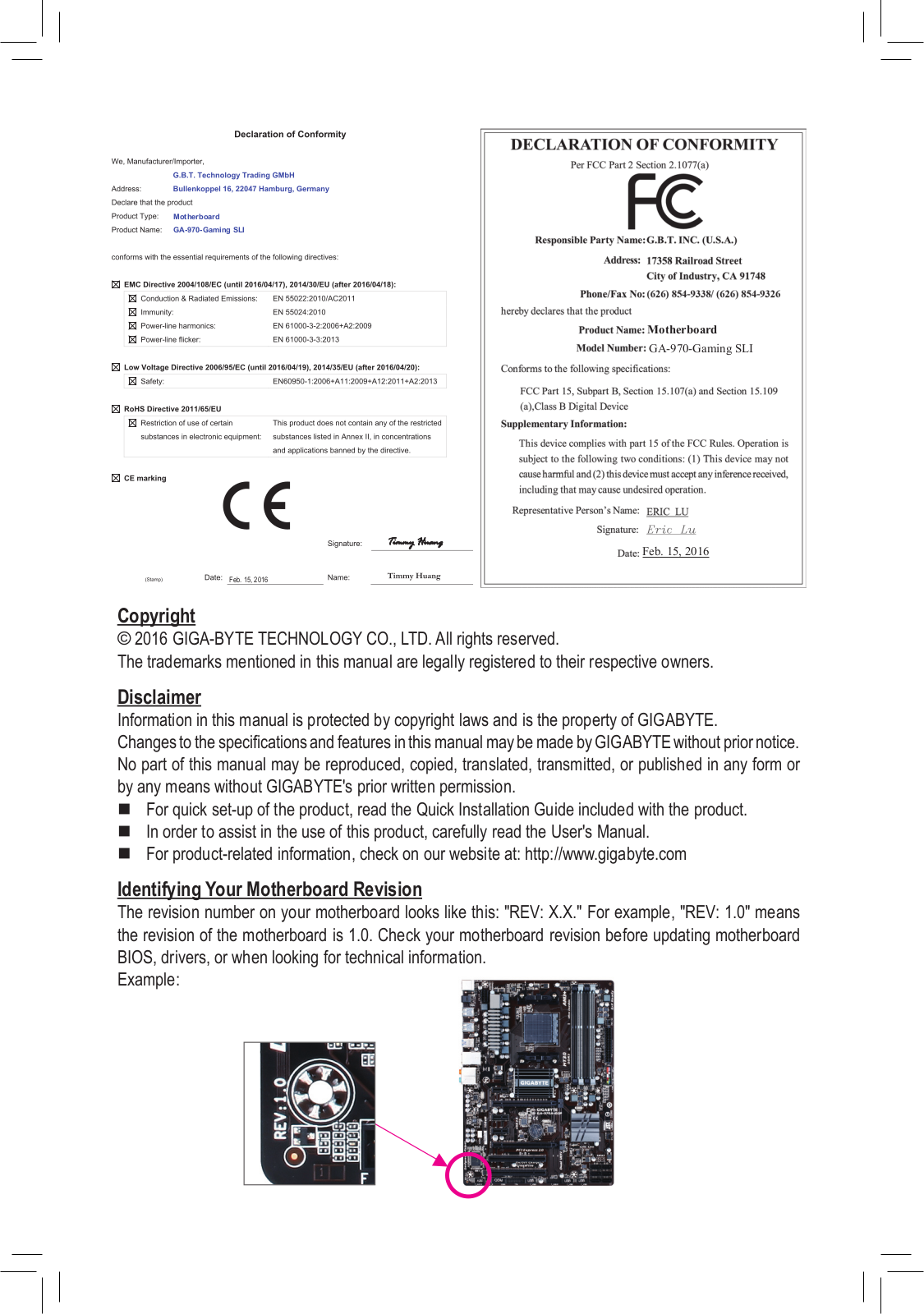
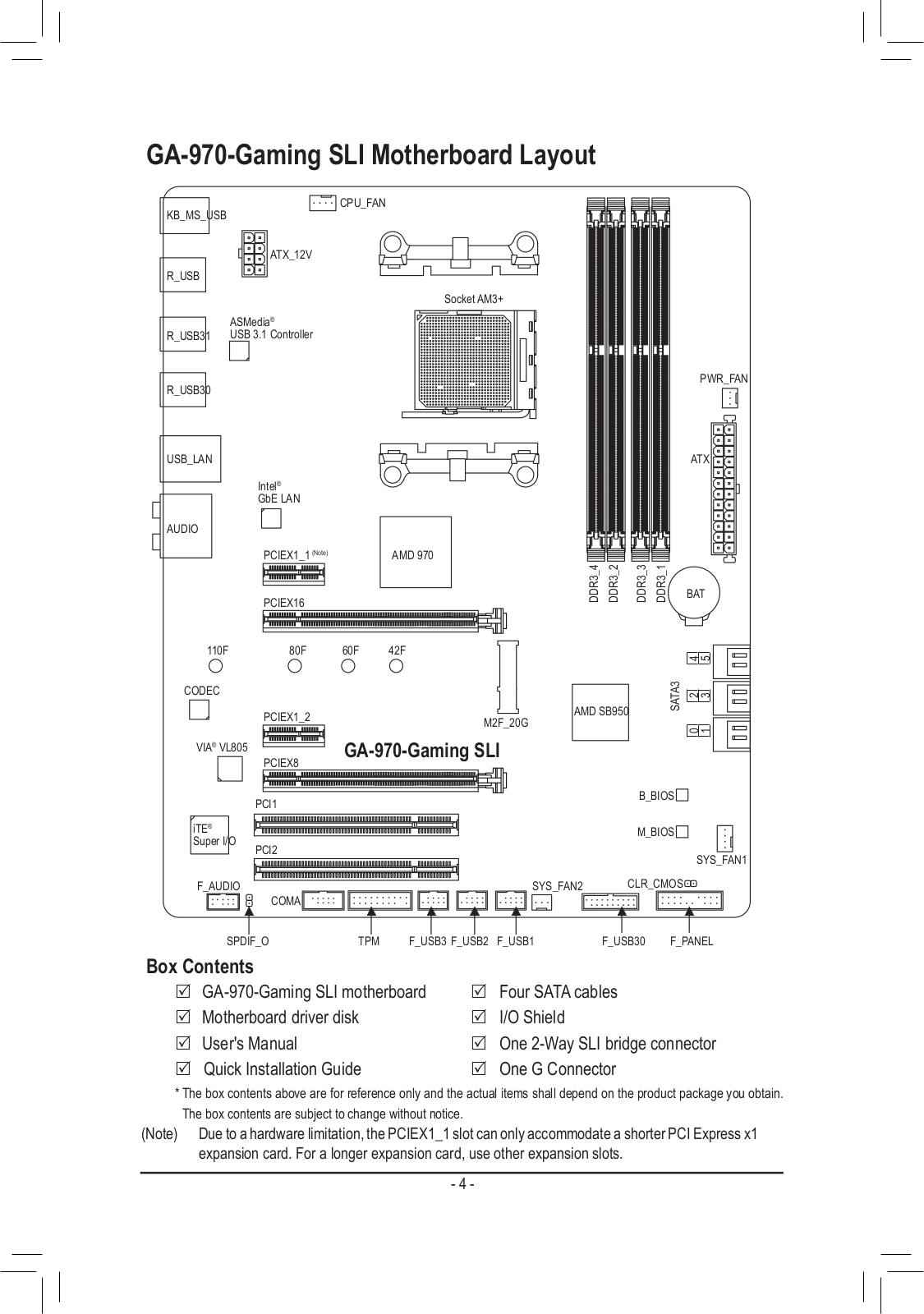
GA-970-GAMING SLI
User Manual
40 pgs
11.46 Mb
0
Table of contents
Loading...
Gigabyte GA-970-GAMING SLI User Manual
...
Gigabyte User Manual
Download
Specifications and Main Features
Frequently Asked Questions
User Manual
Download
Loading...
+
28
hidden pages
Unhide
You need points to download manuals.
1 point = 1 manual.
You can buy points or you can get point for every manual you upload.
Buy points
Upload your manuals
 Loading...