

Page 1
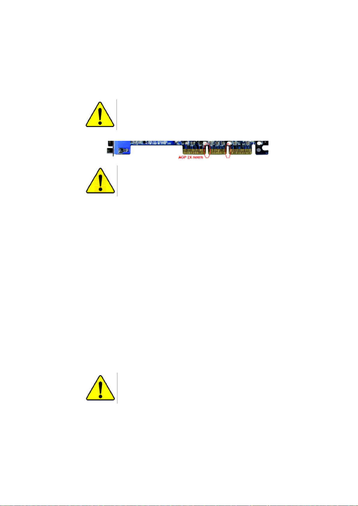
When you installing AGP card, please make sure the following
notice is fully understood and practiced. If your AGP card has
"AGP 4X/8X(1.5V) notch"(show below), please make sure your AGP
card is AGP 4X/8X (1.5V).
AGP 4X/8X notch
Caution: AGP 2X(3.3V) card is not supported by Intel® 845(GE/PE) /
845(E/G) / 850(E)/E7205 / 865(P/G/PE)/875P. You might experience
system unable to boot up normally. Please insert an AGP Pro 4X/8X
(1.5V) card
Example 1: Diamond Vipper V770 golden finger is compatible with
2X/4X mode AGP slot. It can be switched between AGP 2X(3.3V) or 4X
(1.5V) mode by adjusting the jumper. The factory default for this card is
2X(3.3V).
The GA-8PENXP motherboards might not function properly, if you install
this card without switching the jumper to 4X(1.5V) mode in it.
Example 2: Some ATi Rage 128 Pro graphics cards made by
"Power Color", the graphics card manufacturer & some SiS 305 cards,
their golden finger is compatible with 2X/4X mode AGP slot, but they
support 2X(3.3V) only. The GA-8PENXP motherboards might not function
properly, If you install this card in it.
Note : Although Gigabyte's AG32S(G) graphics card is based on
ATi Rage 128 Pro chip, the design of AG32S(G) is compliance
with AGP 4X(1.5V) specification. Therefore, AG32S (G)will work
fine with Intel
®
845(GE/PE) / 845(E/G) / 850(E) /E7205 / 865(P/G/PE)/875P.
based motherboards.
Before you install PCI cards, please remove the Dual BIOS
label from PCI slots if there is one.
Page 2
M The author assumes no responsibility for any errors or omissions
that may appear in this document nor does the author make a
commitment to update the information contained herein.
M Third-party brands and names are the property of theirrespective
owners.
M Please do not remove any labels on motherboard, thismay void the
warranty of this motherboard.
M Due to rapid change in technology, some of the specifications might
be out of date before publication of this booklet.
Page 3

Ausschla ger We g 41, 1F, 20537 Hamburg, Germany
( description of the apparatus, system, installation to which it refers)
(reference to the specification under which con formity is declared)
in accordance with 89/336 EEC-EMC Directive
o EN 55011 Limits and methods of measurement
o EN 55013
o EN 55014 Limits and methods of measurement
o EN 55015 Limits and methods of measurement
o EN 55020
T EN 55022 Limits and methods of measurement
o DIN VDE 0855
o part 10
o part 12
T CE marking
o EN 60065
o EN 60335
of radio disturbance characteristics of
industrial,scientific and medical (ISM
high frequency equipment
Limits and methods of measurement
of radio disturbance characteristics of
broadcast receivers and associated
equipment
of radio disturbance characteristics of
household electrical appliances,
portable tools and similar electrical
apparatus
of radio disturbance characteristics of
fluorescent lamps and luminaries
Immunity from radio interference of
broadcast receivers and associated
equipment
of radio disturbance characteristics of
information technology equipment
Cabled distribution systems; Equipment
for receiving and/or distribution from
sound and television signals
The manufacturer also declares the conformity of above mentioned product
with the actual required safety standards in accordance with LVD 73/23 EEC
Safety requirements for mains operated
electronic and related apparatus for
household and similar general use
Safety of household and similar
electrical appliances
(Stamp)
Declaration of Conformity
We, Manufacturer/Importer
(full address)
G.B.T. Te chnology Träding GMbH
declare that the product
Mother Board
GA-8PENXP
is in conformity with
o EN 61000-3-2*
T EN 60555-2
o EN 61000-3-3* Disturbances in supply systems cause
T EN 60555-3
T EN 50081-1
T EN 50082-1
o EN 55081-2
o EN 55082-2
o ENV 55104
o EN50091-2
(EC conformity marking)
o EN 60950
o EN 50091-1
Manufacturer/Importer
Date : August.11, 2003
Disturbances in supply systems cause
by household appliances and similar
electrical equipment “Harmonics”
by household appliances and similar
electrical equipment “Voltage fluctuations”
Generic emission standard Part 1:
Residual commercial and light industry
Generic immunity standard Part 1:
Residual commercial and light industry
Generic emission standard Part 2:
Industrial environment
Generic emission standard Part 2:
Industrial environment
lmmunity requirements for household
appliances tools and similar apparatus
EMC requirements for uninterruptible
power systems (UPS)
Safety for information technology equipment
including electrical bussiness equipment
General and Safety requirments for
uninterruptible power systems (UPS)
Signature:
Name:
Timmy Huang
Timmy Huang
Page 4

DECLARATION OF CONFORMITY
Per FCC Part 2 Section 2.1077(a)
Responsible PartName:
Address:
Phone/Fax No:
hereby declares that the product
Produ ct Name:
Model Nu mber:
Conforms to the following specifications:
FCC Part 15, Subpart B, Section 15.107(a) and Section 15.109
(a),Class B Digital D evice
Supplementary Information:
This device complies with part 15 of the FCC Rules. Operation is
subject to the following two conditions: (1) This device may not
cause harmful and (2) this device must accept any inference received,
including that may cause undes ired operation.
Representative Person’s Name:
Motherboard
GA-8PENXP
Signature:
G.B.T. INC. (U .S.A.)
17358 Railroad Street
City of Indu stry, CA 91748
(818) 854-9338/ (818) 854-9339
ERIC LU
Eric Lu
Date:
August. 11,2003
Page 5

GA-8PENXP
P4 Titan Series Motherboard
USER'S MANUAL
Pentium®4 Processor Motherboard
Rev. 2001
12ME-8PENXP-2001
Page 6

Table of Content
English
Warning ...................................................................................................... 4
Chapter 1 Introduction .............................................................................. 5
Chapter 2 Hardware Installation Process ...............................................11
Features Summary .......................................................................................... 5
GA-8PENXP Motherboard Layout .................................................................. 8
Block Diagram .................................................................................................. 9
Step 1: Install the Central Processing Unit (CPU) ....................................... 12
Step 1-1: CPU Installation ......................................................................................... 12
Step 1-2: CPU Cooling Fan Installation ..................................................................... 13
Step 2: Install Memory Modules.................................................................... 14
Step 3: Install expansion cards ..................................................................... 17
Step 3-1: AGP Card Installation ................................................................................. 17
Step 3-2: DPS2 (Dual Power System 2) Installation ..................................................... 18
Step 4: Connect ribbon cables, cabinet wires and power supply ............... 19
Step 4-1: I/O Back Panel Introduction ........................................................................ 19
Step 4-2: Connectors & Jumper Setting Introduction .................................................. 21
Chapter 3 BIOS Setup ............................................................................ 37
The Main Menu (For example: BIOS Ver. : F3a) ......................................... 38
Standard CMOS Features ............................................................................. 40
Advanced BIOS Features.............................................................................. 43
Integrated Peripherals .................................................................................. 45
Power Management Setup ............................................................................ 51
- 2 -GA-8PENXP Motherboard
Page 7

PnP/PCI Configurations ...................................................................................54
PC Health Status ............................................................................................. 55
Frequency/Voltage Control .............................................................................. 57
Select Language ............................................................................................. 60
Load Fail-Safe Defaults ................................................................................... 61
Load Optimized Defaults ................................................................................. 62
Set Supervisor/User Password ....................................................................... 63
Save & Exit Setup .......................................................................................... 64
Exit Without Saving ....................................................................................... 65
Chapter 4 Technical Reference .............................................................. 67
@BIOS™ Introduction...................................................................................... 67
EasyTune™ 4 Introduction ............................................................................... 68
DPS2 (Dual Power System 2) Introduction ....................................................... 79
Flash BIOS Method Introduction ...................................................................... 70
2- / 4- / 6-Channel Audio Function Introduction ................................................ 80
Jack-Sensing Introduction............................................................................... 86
UAJ Introduction ............................................................................................ 88
Xpress Recovery Introduction .........................................................................90
English
Chapter 5 Appendix ................................................................................ 93
- 3 -
Table of Content
Page 8

Warning
English
Installing the motherboard to the chassis…
are no slots to attach the spacers, do not become alarmed you can still attach the spacers to the
mounting holes. Just cut the bottom portion of the spacers (the spacer may be a little hard to cut off, so
be careful of your hands). In this way you can still attach the motherboard to the base without worrying
about short circuits. Sometimes you may need to use the plastic springs to isolate the screw from the
motherboard PCB surface, because the circuit wire may be near by the hole. Be careful, don't let the
screw contact any printed circuit write or parts on the PCB that are near the fixing hole, otherwise it may
damage the board or cause board malfunctioning.
Computer motherboards and expansion cards contain very delicate Integrated
Circuit (IC) chips. To protect them against damage from static electricity, you
should follow some precautions whenever you work on your computer.
1. Unplug your computer when working on the inside.
2. Use a grounded wrist strap before handling computer components. If you do not have
one, touch both of your hands to a safely grounded object or to a metal object, such as
the power supply case.
3. Hold components by the edges and try not touch the IC chips, leads or connectors, or
other components.
4. Place components on a grounded antistatic pad or on the bag that came with the
components whenever the components are separated from the system.
5. Ensure that the ATX power supply is switched off before you plug in or remove the ATX
power connector on the motherboard.
If the motherboard has mounting holes, but they don’t line up with the holes on the base and there
- 4 -GA-8PENXP Motherboard
Page 9

Chapter 1 Introduction
Features Summary
Form Factor — 30.5cm x 24.4cm ATX size form factor, 6 layers PCB.
CPU — Socket 478 for Intel® Micro FC-PGA2 Pentium® 4 processor
— Intel Pentium®4 800MHz / 533MHz / 400MHz FSB
— Support Intel ® Pentium ® 4 (Northwood, Prescott) processor
— Support Intel ® Pentium ® 4 Processor with HT Technology
— 2nd cache depend on CPU
Chipset — Intel® Chipset Springdale-PE HOST/AGP/Controller
— ICH5 I/O Controller Hub
Memory — 6 184-pin DDR DIMM sockets
— Supports Dual Channel DDR400/DDR333/DDR266 DIMM
— Supports 128MB/256MB/512MB/1GB unbuffered DRAM
— Supports up to 4GB DRAM (Max)
— Supports only DDR DIMM
I/O Control — ITE8712F
Slots — 1 AGP Pro Slot Compliance with AGP 3.0 specification ,
supporting 4X and 8X transfer rates
— 5 PCI slot supports 33MHz & PCI 2.3 compliant
On-Board IDE — 2 IDE controllers on the Intel ICH5 PCI chipset
provides IDE HDD/CD-ROM (IDE1, IDE2) with PIO, Bus Master
(Ultra DMA33/ATA66/ATA100) operation modes.
— IDE3 and IDE4 Compatible with RAID,Ultra ATA133/100.
Serial ATA — 2 Serial ATA connectors in 150 Mb/s operation mode
— Controlled by ICH5
On-Board Peripherals — 1 Floppy port supports 2 FDD with 360K, 720K,1.2M, 1.44M
and 2.88M bytes.
— 1 Parallel port supports Normal/EPP/ECP mode
— 2 Serial ports (COMA & COMB)
— 8 USB 2.0/1.1 ports (4 x Rear, 4 x Front by cable)
— 3 IEEE1394 (by cable)
— 1 IrDA connector for IR/CIR
— 1 Front Audio connector
to be continued......
English
Due to chipset (Intel 865PE) architecture limitation, DDR 400 memory module is only supported
when using FSB 800 Pentium 4 processor. A FSB 533 Pentium 4 processor will support DDR333
and DDR266 memory module. A FSB 400 Pentium 4 processor will only support DDR 266 memory
module.
Only Silicon Image Sil3112 chip supports Serial ATA(SATA0_SII/SATA1_SII) connectors hot plug
function.
Introduction- 5 -
Page 10

Hardware Monitor — CPU/Power/System Fan Revolution detect
English
On-Board LAN — Builit in Intel® 82547EI (KENAI II CSA) Chipset
On-Board Sound — Realtek ALC658 codec(UAJ)
On-Board IDE RAID — Onboard Giga RAID IT8212F chipset
On-Board SATA RAID — Onboard Silicon Image Sil3112A
— CPU/Power/System Fan Control
— CPU Overheat Warning
— System Voltage Detect
— 1 RJ45 port
— Supports Jack Sensing function
— Line Out / 2 front speaker
— Line In / 2 rear speaker(by s/w switch)
— Mic In / center& subwoofer(by s/w switch)
— SPDIF out / SPDIF In
— CD In / AUX In / Game port
— Supports data striping (RAID 0) or mirroring (RAID 1) or
striping+mirroring (RAID 0+RAID 1)
— Supports JBOD function
— Supports concurrent dual ATA133 IDE controller operation
— Support ATAPI mode for HDD
— Supports IDE bus master operation
— Support ATA133/RAID mode switch by BIOS
— Displays status and error checking messages during boot-up
— Mirroring supports automatic background rebuilds
— Features LBA and Extended Interrupt 13 drive translation in
controller onboard BIOS
— Supports Disk striping (RAID0) or DISK Mirroring (RAID1)
— Supports UDMA up to 150 MB/sec
— AIL UDMA and PIO Modes
— Up to 2 SATA Device
— ACPI and ATA/ATAPI6
— Supports hot plug funcion (SATA0_SII/SATA1_SII)
to be continued......
- 6 -GA-8PENXP Motherboard
Page 11

On-Board IEEE1394 — TSB43AB23
PS/2 Connector — PS/2 Keyboard interface and PS/2 Mouse interface
BIOS — Licensed Phoenix BIOS
— Supports Dual BIOS
— Supports Multi Language
— Supports Face Wizard
— Supports Q-Flash
Additional Features — Supports CPU Dual Power System 2 (DPS2)
— PS/2 Keyboard power on by password
— PS/2 Mouse power on
— External Modem wake up
— STR(Suspend-To-RAM)
— Wake on LAN (WOL)
— AC Recovery
— Poly fuse for keyboard over-current protection
— USB KB/Mouse wake up from S3
— Supports CPU Smart Fan Control function
— Supports @BIOS
— Supports EasyTune 4
— Supports clear password function
Overclocking — Over Voltage (DDR/AGP/CPU) by BIOS
— Over Clock (DDR/AGP/CPU/PCI) by BIOS
English
HT functionality requirement content :
Enabling the functionality of Hyper-Threading Technology for your computer system requires
all of the following platform components:
- CPU: An Intel® Pentium 4 Processor with HT Technology
- Chipset: An Intel® Chipset that supports HT Technology
- BIOS: A BIOS that supports HT Technology and has it enabled
- OS: An operation system that has optimizations for HT Technology
Please set the CPU host frequency in accordance with your processor's specifications.
We don't recommend you to set the system bus frequency over the CPU's specification
because these specific bus frequencies are not the standard specifications for CPU,
chipset and most of the peripherals. Whether your system can run under these specific
bus frequencies properly will depend on your hardware configurations, including CPU,
Chipsets,SDRAM,Cards… .etc.
Introduction- 7 -
Page 12
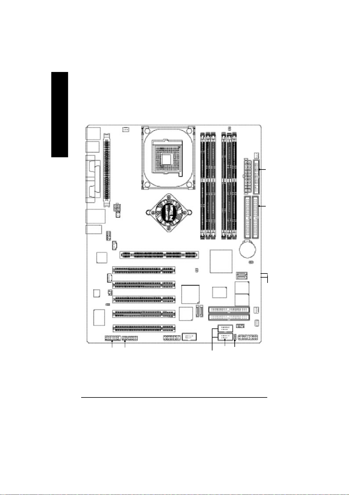
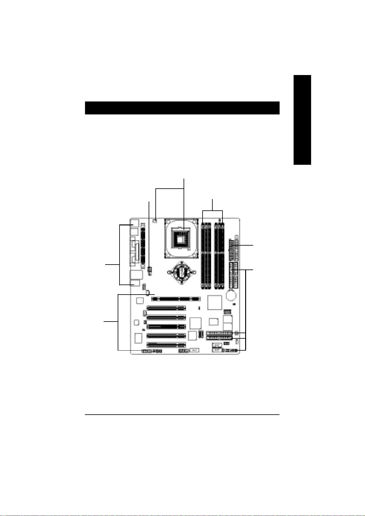
GA-8PENXP Motherboard Layout
English
KB_MS
COMA
USB
AUDIO
CODEC
USB
COMB
KENAI II
ITE8712F
LPT1
LAN
Intel
CI
F_AUDIO
AUX_IN
SUR_CEN
GAME
CPU_FAN
VRM_CONN
ATX_12V
NB-FAN
CD_IN
SPDIF_IO
IR/CIR
P4 Titan
SOCKET478
Intel® Springdale-PE
F2_1394
PCI1
PCI2
PCI3
PCI4
PCI5
AGP Pro
2X_DET
Sil3112
TSB43AB23
F1_1394
GA-8PENXP
DDR3
DDR1
DDR2
ICH5
Giga RAID
IT8212
IDE4
IDE3
SATA0_SII
F_USB1
SATA1_SII
F_USB2
Front USB 2.0
DDR4
RAM_LED
DDR6
DDR5
INFO_LINK
IDE2
BATTERY
MAIN
BIOS
BACKUP
BIOS
F_PANEL
PWR_LED
ATX
CLR_PWD
SATA1_SB
SATA0_SB
WOL
PWR_FAN
FLOPPY
IDE1
Serial ATA
SYS_FAN
- 8 -GA-8PENXP Motherboard
Page 13
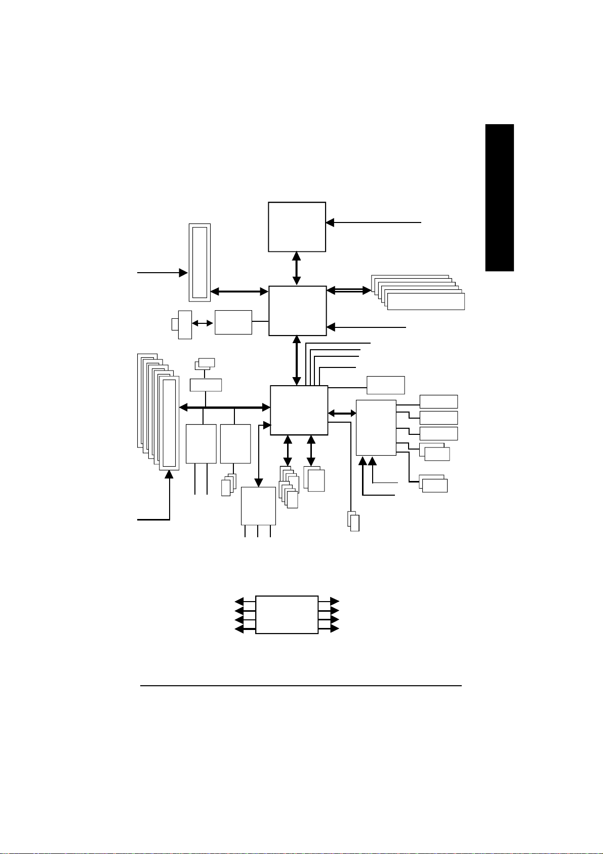
Block Diagram
English
AGPCLK
(66MHz)
5 PCI
PCICLK
(33MHz)
AGP Pro
4X/8X
RJ45
2 Serial ATA
SIL3112
ITE
GigaRAID
IT8212
IDE4
KENAI II
TSB43AB23
IDE3
Intel
IEEE1394
CODEC
MIC
LINE-IN
Pentium 4
Socket 478
CPU
800/533/400MHz
Intel
Springdale-PE
Intel
ICH5
AC97 Link
8 USB
Ports
Channels
LINE-OUT
System Bus
®
ATA33/
66/100
IDE
CPUCLK+/- (200/133/100MHz)
400/333/266MHz
MCHCLK (200/133/100MHz)
66 MHz
33 MHz
48 MHz
LPC BUS
14.318 MHz
BIOS
IT8712F
24 MHz
33 MHz
2 Serial ATA
DDR RAM
Game Port
Floppy
LPT Port
PS/2 KB/Mouse
2 COM Ports
PCICLK (33MHz)
USBCLK (48MHz)
14.318 MHz
33 MHz
CLK GEN
CPUCLK+/- (200/133/100MHz)
AGPCLK (66MHz)
MCHCLK (200/133/100MHz)
ICH3V66 (66MHz)
Introduction- 9 -
Page 14

English
- 10 -GA-8PENXP Motherboard
Page 15
Chapter 2 Hardware Installation Process
To set up your computer, you must complete the following steps:
Step 1- Install the Central Processing Unit (CPU)
Step 2- Install memory modules
Step 3- Install expansion cards
Step 4- Connect ribbon cables, cabinet wires, and power supply
Step1
English
Step 4
Step3
Step4
Step 2
Step 4
Step 4
Congratulations you have accomplished the hardware installation!
Turn on the power supply or connect the power cable to the power outlet. Continue with
the BIOS/software installation.
- 11 - Hardware Installation Process
Page 16
Step 1: Install the Central Processing Unit (CPU)
English
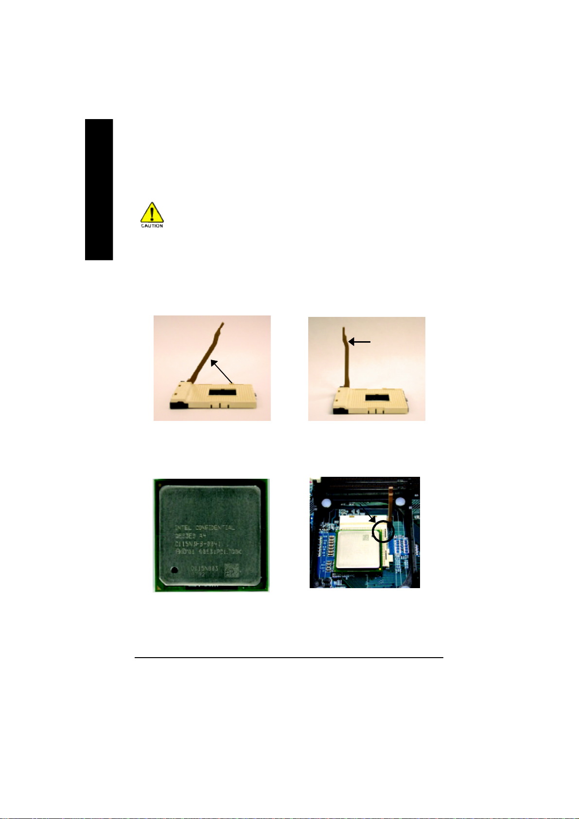
Step 1-1: CPU Installation
Before installing the processor, adhere to the following warning:
1.Please make sure the CPU type is supported by the motherboard.
2.If you do not match the CPU socket Pin 1 and CPU cut edge well, it will
cause improper installation. Please change the insert orientation.
Angling the
rod to 65
0
Socket
Actuation
Lever
1. Angling the rod to 65-degree maybe feel a
kind of tight , and then continue pull the rod
to 90-degree when a noise “cough” made.
2. Pull the rod to the 90-degree directly.
Pin1 indicator
3. CPU Top View
Pin1 indicator
4. Locate Pin 1 in the socket and look
for a (golden) cut edge on the CPU
upper corner. Then insert the CPU
into the socket.
- 12 -GA-8PENXP Motherboard
Page 17

Step 1-2 : CPU Heat Sink Installation
Before installing the CPU cooling fan, adhere to the following warning:
1.Please use Intel approved cooling fan.
2.We recommend you to apply the thermal tape to provide better heat
conduction between your CPU and cooling fan.
(The CPU cooling fan might stick to the CPU due to the hardening of
the thermal paste. During this condition if you try to remove the cool-
ing fan, you might pull the processor out of the CPU socket alone with
the cooling fan, and might damage the processor. To avoid this from
happening, we suggest you to either use thermal tape instead of
thermal paste, or remove the cooling fan with extreme caution.)
3. Make sure the CPU fan power cable is plugged in to the CPU fan
connector, this completes the installation.
Please refer to CPU cooling fan user's manual for more detail
installation procedure.
English
1. Fasten the heatsink supporting-base
onto the CPU socket on the
mainboard.
2. Make sure the CPU fan is plugged to
the CPU fan connector, than install
complete.
- 13 - Hardware Installation Process
Page 18
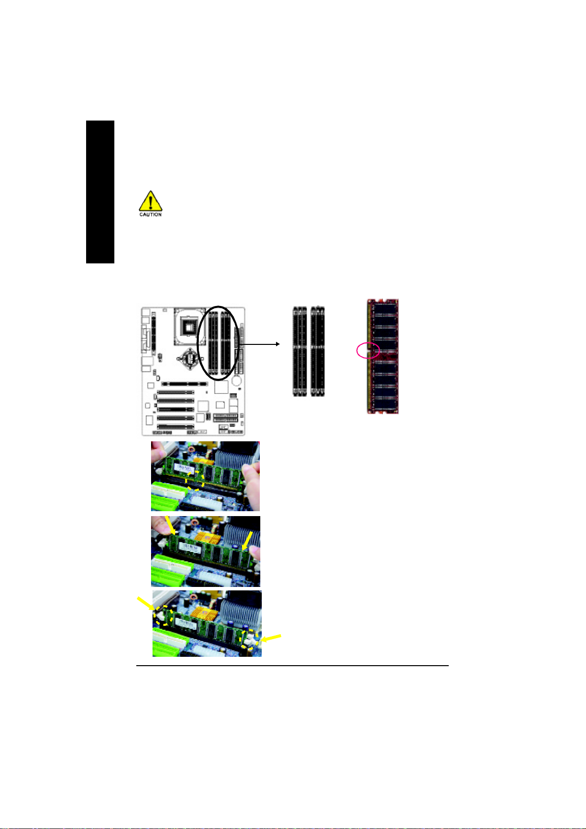
Step 2: Install memory modules
English
The motherboard has 6 dual inline memory module (DIMM) sockets. The BIOS will automatically
detects memory type and size. To install the memory module, just push it vertically into the DIMM
socket. The DIMM module can only fit in one direction due to the notch. Memory size can vary
between sockets.
Before installing the memory modules, adhere to the following warning:
1. When DIMM LED is ON, do not install / remove DIMM from socket.
2. Please note that the DIMM module can only fit in one direction due to
the one notch. Wrong orientation will cause improper installation. Please
change the insert orientation.
Notch
DDR
1. The DIMM slot has a notch, so the DIMM
memory module can only fit in one direction.
2. Insert the DIMM memory module vertically into
the DIMM slot. Then push it down.
3. Close the plastic clip at both edges of the DIMM
slots to lock the DIMM module.
Reverse the installation steps when you wish
to remove the DIMM module.
- 14 -GA-8PENXP Motherboard
Page 19

DDR Introduction
Established on the existing SDRAM infrastructure, DDR (Double Data Rate) memory is a high performance and cost-effective solution that allows easy adoption for memory vendors, OEMs, and system
integrators.
DDR memory is a great evolutionary solution for the PC industry that builds on the existing
SDRAM architecture, yet make the awesome advances in solving the system performance bottle-
neck by doubling the memory bandwidth. Nowadays, with the highest bandwidth of 3.2GB/s of
DDR400 memory and complete line of DDR400/333/266/200 memory solutions, DDR memory is
the best choice for building high performance and low latency DRAM subsystem that are suitable
for servers, workstations, and full range of desktop PCs.
Dual Channel DDR:
8PENXP supports Dual Channel Technology.
When Dual Channel Technology is activated, the bandwidth of memory bus will be double the original one,
with the fastest speed at 6.4GB/s DDR400.
8PENXP includes six DIMM slots, and each Channel has 3 DIMMs as following:
Channel A : DIMM 1, 2, 3
Channel B : DIMM 4, 5, 6
Below are the explanations:
1. One, three, or five DDR memory modules are installed: The Dual Channel Technology will
not operate when one, three, or five DDR memory modules are installed and they will only
work as Single Channel.
2. Two DDR memory modules are installed (the same memory size and type): The Dual Chan-
nel Technology will operate when two DDR memory modules are inserted individually into
Channel A and Channel B (DIMM 1 pairs up with DIMM 4, DIMM 2, 5 and DIMM 3, 6).
However, if the two DDR memory modules are inserted into the same Channel (DIMM 1,2,
3 or DIMM 4,5,6) then Dual Channel Technology will not operate.
3. Three or five DDR memory modules are installed: Please note that The Dual Channel Tech-
nology will not operate when three or five DDR memory modules are installed; part of them
will not be detected.
4. If four DDR memory modules are installed (two pairs of DDR memory modules with the
same memory size and type): The Dual Channel Technology will operate when a pair of
DDR memory modules are inserted into DIMM1, 4 and another pair into DIMM 2,5.
English
- 15 - Hardware Installation Process
Page 20

English
The following tables include all memory-installed combination types:
(Please note that those types not in the tables will not boot up.)
5. If six DDR memory modules are installed: To activate the Dual Channel Technology and to
make the size of each DDR memory module detected, please use six DDR memory mod-
ules with identical size and type and insert them into the six DIMMs following the sequence
below:
DIMM 1: Double or Single Side
DIMM 2: Single Side
DIMM 3: Single Side
DIMM 4: Double or Single Side (if DIMM1 is inserted a double-side module, then DIIMM4
must also be inserted a double-side one.)
DIMM 5: Single Side
DIMM 6: Single Side
l Figure 1: Dual Channel Technology (DS: Double Side, SS: Single Side)
DIMM 1 DIMM 2 DIMM 3 DIMM 4 DIMM5 DIMM6
DS/SS X X DS/SS X X
2 memory modules
4 memory modules
6 memory modules
X DS/SS X X DS/SS X
X X DS/SS X X DS/SS
DS/SS DS/SS X DS/SS DS/SS X
DS/SS SS SS DS/SS SS SS
l Figure 2: Don't operate Dual Channel Technology (DS: Double Side, SS: Single Side)
DIMM 1 DIMM 3 DIMM5
DS/SS X X
1 memory module
2 memory modules
3 memory modules
X DS/SS X
X X DS/SS
DS/SS DS/SS X
DS/SS SS SS
- 16 -GA-8PENXP Motherboard
Page 21

Step 3: Install expansion cards
Step 3-1: AGP Card Installation
1. Read the related expansion card's instruction document before install the expansion card
into the computer.
2. Remove your computer's chassis cover, screws and slot bracket from the computer.
3. Press the expansion card firmly into expansion slot in motherboard.
4. Be sure the metal contacts on the card are indeed seated in the slot.
5. Replace the screw to secure the slot bracket of the expansion card.
6. Replace your computer's chassis cover.
7. Power on the computer, if necessary, setup BIOS utility of expansion card from BIOS.
8. Install related driver from the operating system.
Please align the AGP card to the onboard AGP PRO
slot and press firmly down on the slot.
English
If you are installing a AGP PRO graphic card, please
remove the protecting plate first.
When an AGP 2X (3.3V) card is installed the 2X_DET will light up, indicating a non-supported
graphics card is inserted. Informing users that system might not boot up normally due to AGP 2X
(3.3V) is not supported by the chipset.
- 17 - Hardware Installation Process
Page 22

Step 3-2: DPS2 (Dual Power System 2) Installation
What is DPS2 ?
English
DPS2 (Dual Power System 2) is a daughter card which can provide you the Dual Power System
function. A cool stylish neon blue DPS2 that supply a total 6-phase power circuit design, delivers
a high durable power design for the new generation Intel® platform.
How to install a DPS2 ?
The DPS2 can work in a Dual Power System:
• Parallel Mode :
DPS2 and motherboard CPU power can work
simultaneously, providing a total of 6-phase power
circuit.
1. The DPS2 connector has a notch, so the DPS2 can only fit in one direction.
2. Insert the DPS2 vertically into the socket and then push it down.
3. Fix the DPS2 on the motherbard with the clip.
4. Reverse the installation steps if you want to remove the DPS2.
- 18 -GA-8PENXP Motherboard
Page 23
Step 4: Connect ribbon cables, cabinet wires and
power supply
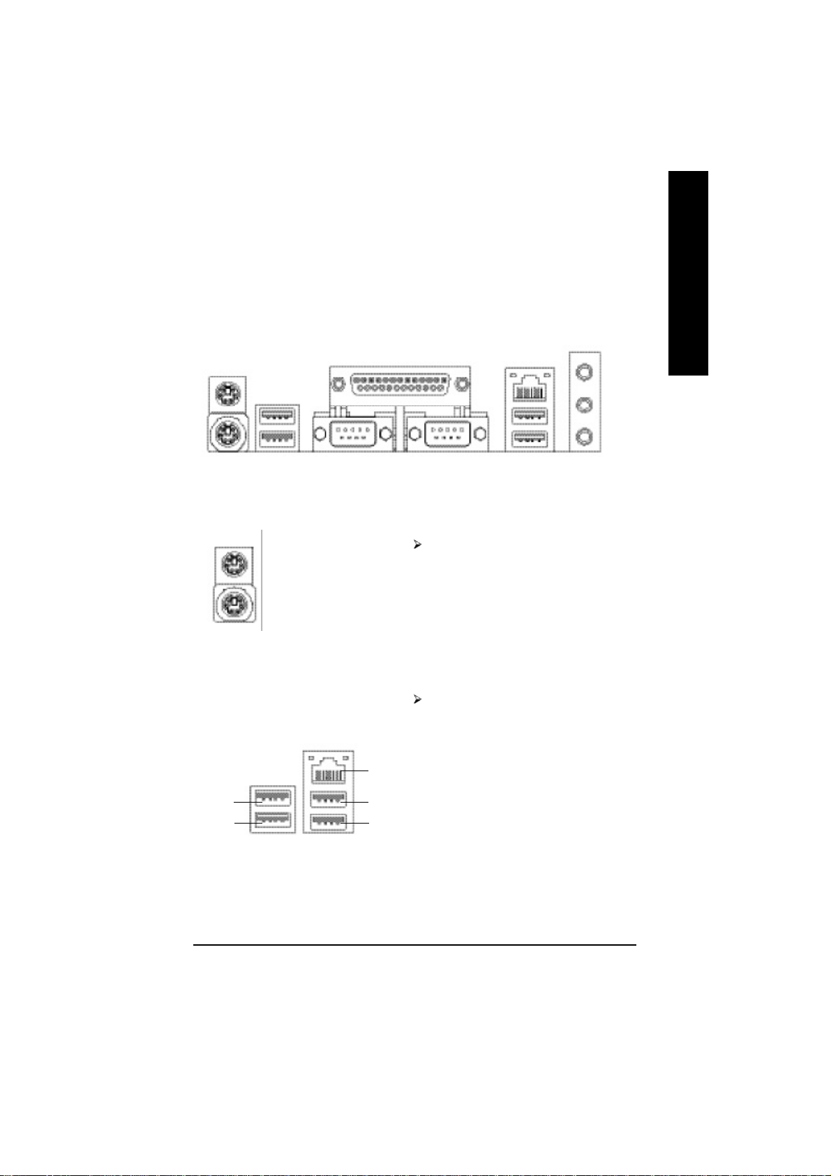
Step 4-1: I/O Back Panel Introduction
u
v
w
u PS/2 Keyboard and PS/2 Mouse Connector
x
English
y
PS/2 Mouse Connector
(6 pin Female)
PS/2 Keyboard Connector
(6 pin Female)
v/x USB/LAN Connector
USB 0
USB 1
LAN
USB 2
USB 3
Th is connect or supp orts stand ard PS/2
keyboard and PS/2 mouse.
Before you connect your device(s) into USB
connector(s), please make sure your device(s)
such as USB keyboard,mouse, scanner, zip,
speaker...etc. Have a standard USB interface.
Al so make s ure your OS s uppor ts USB
controller. If your OS does not support USB
controller, please contact OS vendor for pos-
sible patch or driver upgrade. For more infor-
mation please contact your OS or device(s)
vendors.
- 19 - Hardware Installation Process
Page 24
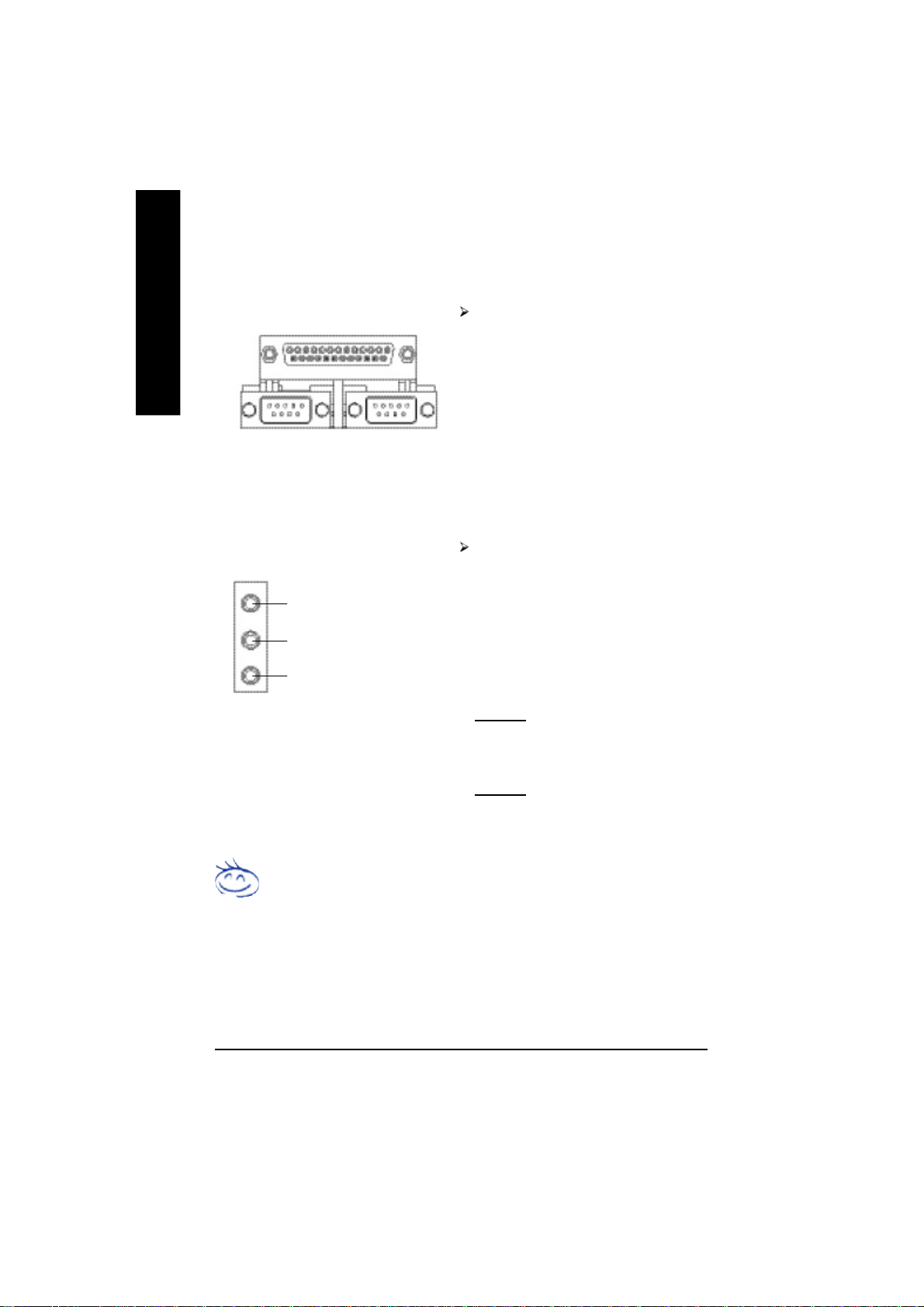
w Parallel Port and Serial Ports (COMA / COMB)
English
y Audio Connectors
Parallel Port
(25 pin Female)
COMA COMB
Serial Port (9 pin Male)
Line In (Rear Speaker)
Line Out (Front Speaker)
MIC In (Center and Subwoofer)
This connector supports 2 standard COM ports
and 1 Parallel port. Device like printer can be
connected to Parallel port; mouse and modem
etc. can be connected to Serial ports.
After install onboard audio driver, you may connect speaker to Line Out jack, microphone to
MIC In jack. Device like CD-ROM,walkman etc.
can be connected to Line-In jack.
Please note:
You are able to use 2-/4-/6-channel audio feature by S/W selection.
If you want to enable 6-channel function, you
have 2 choose for hardware connection.
Method1:
Connect "Front Speaker" to "Line Out"
Connect "Rear Speaker" to "Line In"
Connect "Center and Subwoofer" to "MIC Out ".
Method2:
You can refer to page 30, and contact your
nearest dealer for optional SUR_CEN cable.
If you want the detail information for 2-/4-/6-channel audio setup
installation, please refer to page 82.
- 20 -GA-8PENXP Motherboard
Page 25
Step 4-2 :Connectors & Jumper Setting Introduction
3
1
14
English
2
5
7
6
16
19
15
20
17
26
1) ATX_12V
2) ATX
3) CPU_FAN
4) SYS_FAN
5) PWR_FAN
6) NB_FAN
7) FDD
8) IDE1 / IDE2
9) IDE3 / IDE4
10) SATA0_SB / SATA1_SB
11) SATA0_SII / SATA1_SII
12) F_PANEL
13) PWR_LED
14) RAM_LED
15) 2X_DET
232818
8
29
10
9
4
27
24
12
22
11 21
1325
16) F_AUDIO
17) SUR_CEN
18) SPDIF_IO
19) CD_IN
20) AUX_IN
21) F_USB1 / F_USB2
22) IR_CIR
23) GAME
24) INFO_LINK
25) F1_1394/F2_1394
26) CI
27) WOL
28) CLR_PWD
29) BAT
- 21 - Hardware Installation Process
Page 26
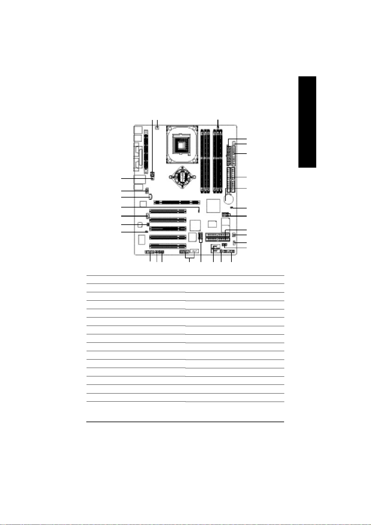
1) ATX_12V (+12V Power Connector)
English
2) ATX (ATX Power)
This connector (ATX_12V) supplies the CPU operation voltage (Vcore).
If this "ATX_12V connector" is not connected, system cannot boot.
Pin No. Definition
43
1
2
1 GND
2 GND
3 +12V
4 +12V
AC power cord should only be connected to your power supply unit after ATX power cable and other
related devices are firmly connected to the mainboard.
11
20
1
10
Pin No. Definition
1 3.3V
2 3.3V
3 GND
4 VCC
5 GND
6 VCC
7 GND
8 Power Good
9 5V SB (stan d by +5V)
10 +12V
11 3.3V
12 -12V
13 GND
14 PS_ON(soft on/off)
15 GND
16 GND
17 GND
18 -5V
19 VCC
20 VCC
- 22 -GA-8PENXP Motherboard
Page 27
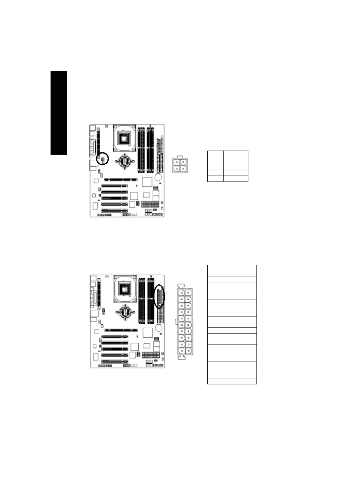
3) CPU_FAN (CPU Fan Connector)
Please note, a proper installation of the CPU cooler is essential to prevent the CPU from running under
abnormal condition or damaged by overheating. The CPU fan connector supports Max. current up to
600 mA.
Pin No. Definition
1
1 GND
2 +12V
3 Sense
4) SYS_FAN (System Fan Connector)
This connector allows you to link with the cooling fan on the system case to lower the system temperature.
English
1
- 23 - Hardware Installation Process
Pin No. Definition
1 GND
2 +12V
3 Sense
Page 28
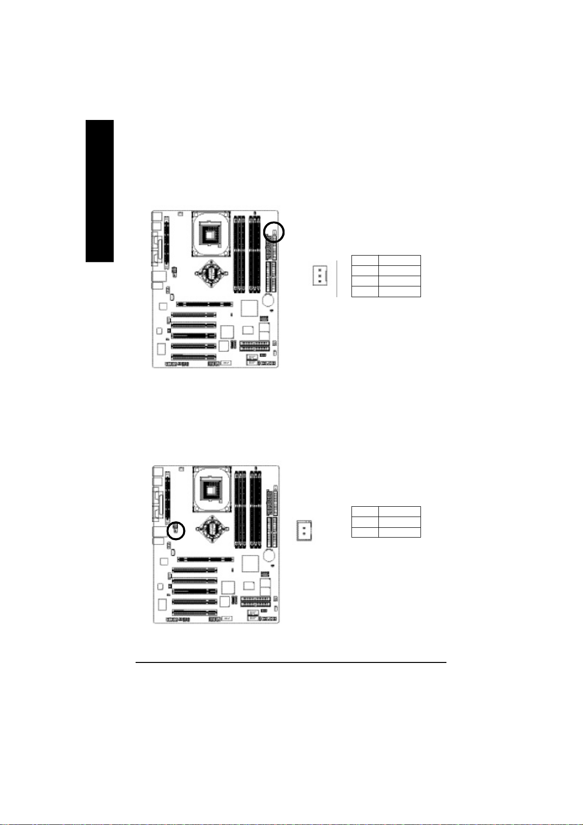
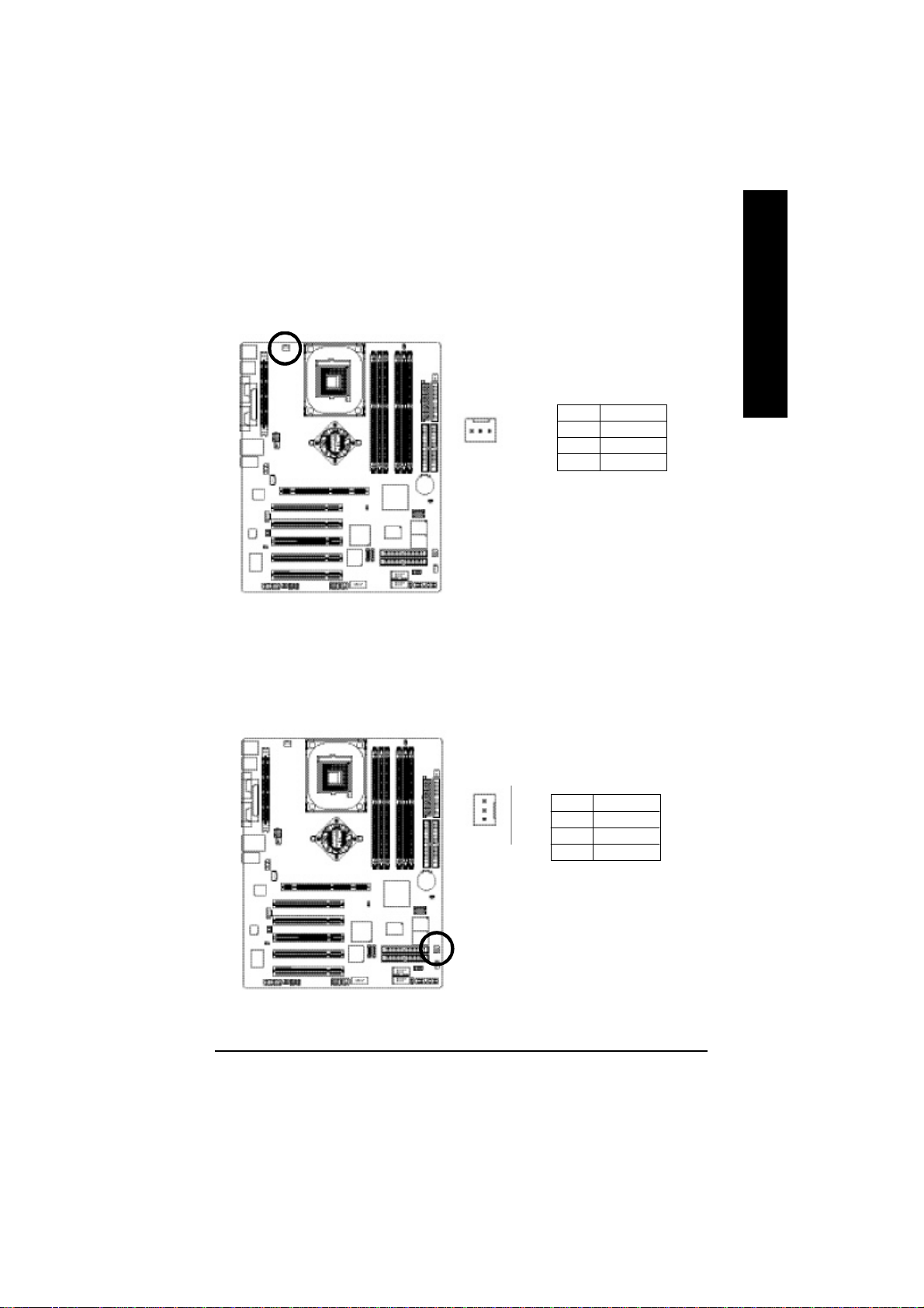
5) PWR_FAN (Power Fan Connector)
English
6) NB_FAN (Chip Fan Connector)
This connector allows you to link with the cooling fan on the system case to lower the system temperature.
Pin No. Definition
1 GND
1
If you installed wrong direction, the chip fan will not work. Sometimes will damage the chip fan.(Usually
black cable is GND)
2 +12V
3 Sense
1
- 24 -GA-8PENXP Motherboard
Pin No. Definition
1 VCC
2 GND
Page 29
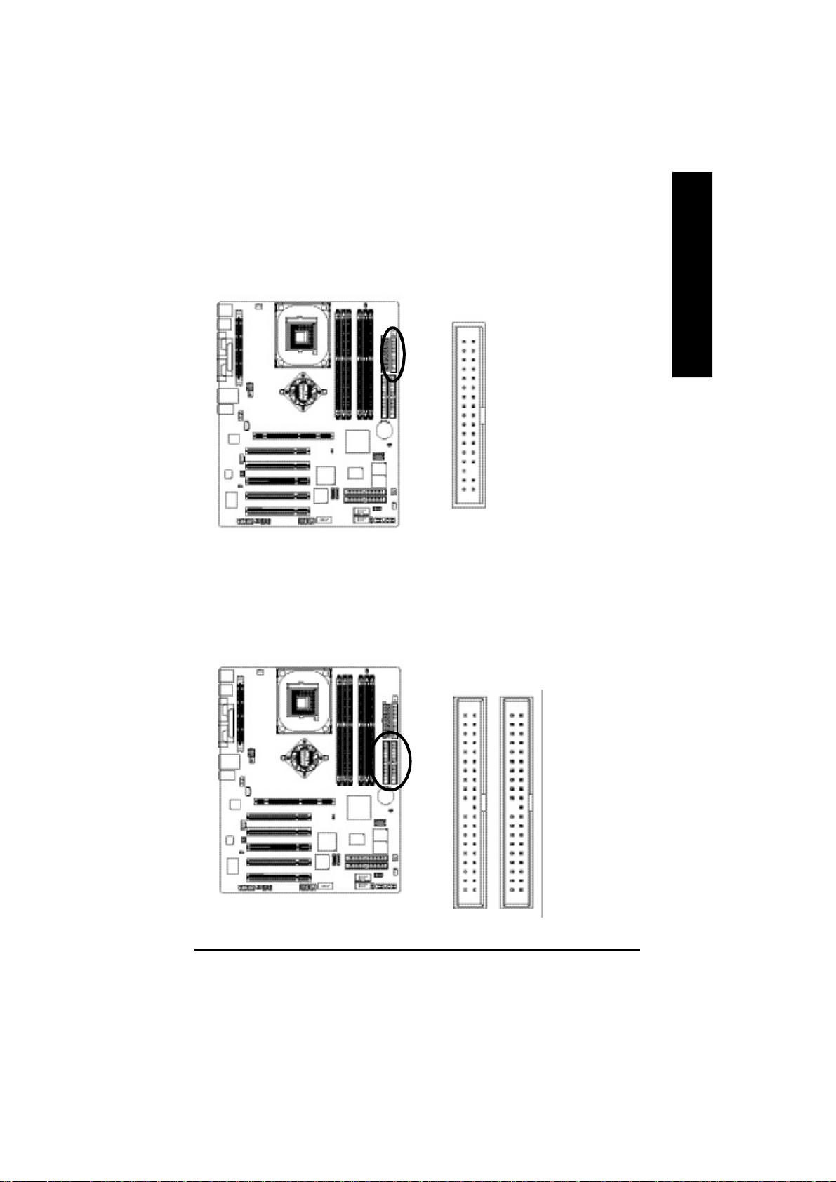
7) FDD (Floppy Connector)
Please connect the floppy drive ribbon cables to FDD. It supports 360K, 1.2M, 720K, 1.44M and
2.88M bytes floppy disk types.
The red stripe of the ribbon cable must be the same side with the Pin1.
English
34
2
8) IDE1 / IDE2 (IDE1 / IDE2 Connector)
Important Notice:
Please connect first hard disk to IDE1 and connect CD-ROM to IDE2.
The red stripe of the ribbon cable must be the same side with the Pin1.
33
1
3940
12
IDE2
- 25 - Hardware Installation Process
IDE1
Page 30
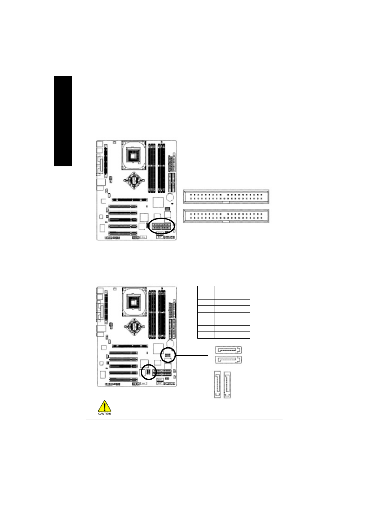
9) IDE3 / IDE4 (RAID/ATA133, Green Connector)
English
Important Notice: The red stripe of the ribbon cable must be the same side with the Pin1. If you wish to
use IDE3 and IDE4, please use it in unity with BIOS (either RAID or ATA133). Then, install the correct
driver to have proper operation. For details, please refer to the ITE RAID manual.
(BIOS Default Value :RAID, If you want to use
ATA function, please change “Integrated
Peripherals-GigaRAID Function “ to “ATA”)
2
40
IDE4
IDE3
1
39
10/11) [SATA0_SB / SATA1_SB];[SATA0_SII /SATA1_SII] (Serial ATA Connector)
You can connect the Serial ATA device to this connector, it provides you high speed transfer rates
(150MB/sec).
Pin No. Definition
1 GND
2 TXP
3 TXN
4 GND
5 RXN
6 RXP
7 GND
17
SATA1_SB
SATA0_SB
17
7
7
SATA1_SIISATA0_SII
1
These two Serial ATA(SATA0_SII/SATA1_SII) connectors support hot plug function.
- 26 -GA-8PENXP Motherboard
1
Page 31

12) F_PANEL (2 x 10 pins Connector)
Please connect the power LED, PC speaker, reset switch and power switch etc. of your chassis front
panel to the F_PANEL connector according to the pin assignment above.
English
MSG+
HD-
HD+
Soft Power
Connector
MSG-
PW+
PW-
1
RES+
NC
RES-
Reset Swit ch
Speaker Connector
SPEAK+
SPEAK-
1
20
19
Message LED/
Power/
Sleep LED
2
1
1 1
1
IDE Hard Dis k Active LED
HD (IDE Hard Disk Active LED) Pin 1: LED anode(+)
(Blue) Pin 2: LED cathode(-)
SPK (Speaker Connector) Pin 1: VCC(+)
(Amber) Pin 2- Pin 3: NC
Pin 4: Data(-)
RES (Reset Switch) Open: Normal Operation
(Green) Close: Reset Hardware System
PW (Soft Power Connector) Open: Normal Operation
(Red) Close: Power On/Off
MSG(Message LED/ Power/ Sleep LED) Pin 1: LED anode(+)
(Yellow) Pin 2: LED cathode(-)
NC (Purple) NC
- 27 - Hardware Installation Process
Page 32

13) PWR_LED
English
PWR_LED is connect with the system pow er indicator to indicate whether the system is on/off.
It will blink when the system enters suspend mode. If you use dual color LED, power LED will turn to
another color.
1
Pin No. Definition
1 MPD+
2 MPD-
3 MPD-
14) RAM_LED
Do not remove memory modules while RAM_LED is on. It might cause short or other unexpected damages due to the stand by voltage. Remove memory modules only when AC power cord is disconnected.
_
+
- 28 -GA-8PENXP Motherboard
Page 33

15) 2X_DET
When an AGP 2X (3.3V) card is installed the 2X_DET will light up, indicating a non-supported graphics
card is inserted. Informing users that system might not boot up normally due to AGP 2X (3.3V) is not
supported by the chipset.
_
+
16) F_AUDIO (Front Audio Connector)
If you want to use Front Audio connector, you must remove 5-6, 9-10 Jumper. In order to utilize the
front audio header, your chassis must have front audio connector. Also please make sure the pin
assigment on the cable is the same as the pin assigment on the MB header. To find out if the chassis
you are buying support front audio connector, please contact your dealer.Please note, you can have
the alternative of using front audio connector or of using rear audio connector to play sound.
English
Pin No. Definition
1 MIC
2 GND
1
2
10
9
- 29 - Hardware Installation Process
3 REF
4 Power
5 Front Audio (R)
6 Rear Audio (R)
7 Reserved
8 No Pin
9 Front Audio (L)
10 Rear Audio (L)
Page 34

17) SUR_CEN (Surround Center Connector)
English
Please contact your nearest dealer for optional SUR_CEN cable.
6 5
2
1
Pin No. Definition
1 SUR OUTL
2 SUR OUTR
3 GND
4 No Pin
5 CENTER_OUT
6 BASS_OUT
18) SPDIF_IO (SPDIF Out Connector)
The SPDIF output is capable of providing digital audio to external speakers or compressed AC3
data to an external Dolby Digital Decoder. Use this feature only when your stereo system has digital
input function. Use SPDIF IN feature only when your device has digital output function.
Be careful with the polarity of the SPDIF_IO connector. Check the pin assignment carefully while
you connect the SPDIF_IO cable, incorrect connection between the cable and connector will make
the device unable to work or even damage it. For optional SPDIF_IO cable, please contact your
local dealer.
6
2
5
1
- 30 -GA-8PENXP Motherboard
Pin No. Definition
1 VCC
2 No Pin
3 SPDIF
4 SPDIFI
5 GND
6 GND
Page 35

19) CD_IN (CD In Connector)
Connect CD-ROM or DVD-ROM audio out to the connector.
1
20) AUX_IN (AUX In Connector)
Connect other device (such as PCI TV Tunner audio out) to the connector.
English
Pin No. Definition
1 CD-L
2 GND
3 GND
4 CD-R
Pin No. Definition
1 AUX-L
2 GND
3 GND
1
- 31 - Hardware Installation Process
4 AUX-R
Page 36

21) F_USB1 / F_USB2 (Front USB Connector, Yellow)
English
Be careful with the polarity of the front USB connector. Check the pin assignment while you
connect the front USB cable. Please contact your nearest dealer for optional front USB cable.
Be careful with the polarity of the F_USB connector. Check the pin assignment carefully while you
connect the F_USBcable, incorrect connection between the cable and connector will make the
device unable to work or even damage it. For optional F_USB cable, please contact your local dealer.
2 10
F_USB1
F_USB2
1 9
Pin No. Definition
1 Power
2 Power
3 USB Dx-
4 USB Dy-
5 USB Dx+
6 USB Dy+
7 GND
8 GND
9 No Pin
10 NC
22) IR_CIR
Make sure the pin 1 on the IR device is aling with pin one the connector. To enable the IR/CIR
function on the board, you are required to purchase an option IR/CIR module. For detail information
please contact your autherized Giga-Byte distributor. To use IR function only, please connect IR
module to Pin1 to Pin5.
Be careful with the polarity of the IR connector. Check the pin assignment carefully while you
connect the IR cable, incorrect connection between the cable and connector will make the device
unable to work or even damage it. For optional IR cable, please contact your local dealer.
Pin No. Definition
1 VCC
2 NC
3 IRRX
6 10
1 5
4 GND
5 IRTX
6 NC
7 CIRRX
8 +5VSB
9 CIRTX
10 NC
- 32 -GA-8PENXP Motherboard
Page 37

23) GAME (Game Connector)
This connector supports joystick, MIDI keyboard and other relate audio devices.
Pin No. Definition
1 VCC
2 GRX1_R
3 GND
2
1
16
15
4 GPSA2
5 VCC
6 GPX2_R
7 GPY2_R
8 MSI_R
9 GPSA1
10 GND
11 GPY1_R
12 VCC
13 GPSB1
14 MSO_R
15 GPSB2
16 No Pin
24) INFO_LINK
This connector allows you to connect some external devices to provide you extra function.
English
Pin No. Definition
1 SMBCLK
102
1
9
2 VCC
3 SMBDATA
4 GPIO
5 GND
6 GND
7 No Pin
8 NC
9 +12V
10 +12V
- 33 - Hardware Installation Process
Page 38

25) F1_1394/F2_1394 ( IEEE 1394 Connector)
English
Please Note: Serial interface standard set by Institute of Electrical and Electronics Engineers , which
has features like high speed, high bandwidth and hot plug.
Be careful with the polarity of the F1_1394/F2_1394 connector. Check the pin assignment carefully
while you connect the IEEE 1394 cable, incorrect connection between the cable and connector will
make the device unable to work or even damage it. For optional IEEE 1394 cable, please contact your
local dealer.
F1_1394
10
2
1
9
Pin No. Definition
1 TPA2+
2 TPA23 GND
4 GND
5 TPB2+
6 TPB27 Power
8 Power
9 No Pin
F1_1394
10 GND
F2_1394
F2_1394
2
1
16
15
Pin No. Definition
1 Power
2 Power
3 TPA0+
4 TPA05 GND
6 GND
7 TPB0+
8 TPB09 Power
10 Power
11 TPA1+
12 TPA113 GND
14 No Pin
15 TPB1+
16 TPB1-
- 34 -GA-8PENXP Motherboard
Page 39

26) CI (CASE OPEN)
This 2-pin connector allows your system to enable or disable the "Case Open" item in BIOS, if the
system case begin remove.
English
1
Pin No. Definition
1 Signal
2 GND
27) WOL (Wake On LAN)
This connector allows the remove servers to manage the system that installed this motherboard via
your network adapter which also supports WOL.
Pin No. Definition
1
1 +5V SB
2 GND
3 Signal
- 35 - Hardware Installation Process
Page 40

28) CLR_PWD
English
29) BATTERY
When Jumper is set to "open" and system is restarted, the password that is set will be cleared.
On the contrary when Jumper is set to "close", the current status remains.
Open: Clear Password
1
Close: Normal
1
+
CAUTION
Da ng er of exp lo sio n if bat ter y is incor rectl y
replaced.
Replace only with the same or equivalent type recommended by the manufacturer.
Di spo se of u sed bat teri es acco rdi ng to t he
manufacturer's instructions.
If you want to erase CMOS...
1. Turn OFF the computer and unplug the power cord.
2. Remove the battery, wait for 30 second.
3. Re-install the battery.
4. Plug the power cord and turn ON the computer.
- 36 -GA-8PENXP Motherboard
Page 41

Chapter 3 BIOS Setup
BIOS Setup is an overview of the BIOS Setup Program. The program that allows users to modify the
basic system configuration. This type of information is stored in battery-backed CMOS RAM so that it
retains the Setup information when the power is turned off.
English
ENTERING
Powering ON the computer and pressing <Del> immediately will allow you to enter Setup. If you require
more advanced BIOS settings, please go to "Advanced BIOS" setting menu. To enter Advanced BIOS
setting menu, press "Ctrl+F1" key on the BIOS screen.
CONTR OL
<á> Move to previous item
<â> Move to next item
<ß> Move to the item in the left hand
<à> Move to the item in the right hand
Enter Select item
<Esc> Main Menu - Quit and not save changes into CMOS Status Page Setup Menu and
<+/PgUp> Increase the numeric value or make changes
<-/PgDn> Decrease the numeric value or make changes
<F1> General help, only for Status Page Setup Menu and Option Page Setup Menu
<F2> Item Help
<F3> Reserved
<F4> Reserved
<F5> Restore the previous CMOS value from CMOS, only for Option Page Setup Menu
<F6> Load the file-safe default CMOS value from BIOS default table
<F7> Load the Optimized Defaults
<F8> Dual BIOS/Q-Flash function
<F9> System Information
<F10> Save all the CMOS changes, only for Main Menu
S ETUP
KEYS
Option Page Setup Menu - Exit current page and return to Main Menu
8penxp_2001_b.p65 2003/11/26, 下午 05:2537
- 37 - BIOS Setup
Page 42

GETTING HELP
The on-line description of the highlighted setup function is displayed at the bottom of the screen.
English
Press F1 to pop up a small help window that describes the appropriate keys to use and the possible
selections for the highlighted item. To exit the Help Window press <Esc>.
The Main Me nu (For example: BIOS Ver. : F3a)
Once you enter Award BIOS CMOS Setup Utility, the Main Menu (Figure 1) will appear on the screen.
The Main Menu allows you to select from eight setup functions and two exit choices. Use arrow keys to
select among the items and press <Enter> to accept or enter the sub-menu.
Main Menu
Statu s Page Setup Menu / Option Page Setup Menu
CMOS Setup Util ity-Copyright (C) 1984-2003 Award Software
} Standard CMOS Features
} Advanced BIOS Features
} Integrated Peripherals
} Power Management Setup
} PnP/PCI Configurations
} PC Health Status
} Frequ ency/Vol tage Control
ESC: Quit F3: C hange Lan guage
F8: Dual BIOS / Q-Flash F10: Save & Exit Setup
Time, Da te, Hard Disk Type...
Figure 1: Main Menu
Select Language
Load Fail-Safe Defaults
Load Optimized Defaults
Set Supervisor Pa ssword
Set User Password
Sav e & Exit Setup
Exit Without Saving
If you can't find the setting you want, please press "Ctrl+F1" to
search the advanced option widden.
l Standard CMOS Featu res
This setup page includes all the items in standard compatible BIOS.
l Advanced BIOS Features
This setup page includes all the items of Award special enhanced features.
8penxp_2001_b.p65 2003/11/26, 下午 05:2538
- 38 -GA-8PENXP Motherboard
Page 43

l Integrated Peripherals
This setup page includes all onboard peripherals.
l Pow er Management Setup
This setup page includes all the items of Green function features.
l PnP/PCI Configurations
This setup page includes all the configurations of PCI & PnP ISA resources.
l PC Health Status
This setup page is the System auto detect Temperature, voltage, fan, speed.
l Frequen cy/Voltage Control
This setup page is control CPU’s clock and frequency ratio.
l Select Langu age
This setup page is select multi language.
l Load Fail-Safe Defau lts
Fail-Safe Defaults indicates the value of the system parameters which the system would
be in safe configuration.
l Load Optimized Defau lts
Optimized Defaults indicates the value of the system parameters which the system would
be in best performance configuration.
l Set Supervisor password
Change, set, or disable password. It allows you to limit access to the system and Setup,
or just to Setup.
l Set User password
Change, set, or disable password. It allows you to limit access to the system.
l Save & Exit Setup
Save CMOS value settings to CMOS and exit setup.
l Exit Without Saving
Abandon all CMOS value changes and exit setup.
English
8penxp_2001_b.p65 2003/11/26, 下午 05:2539
- 39 - BIOS Setup
Page 44

Standard CMOS Features
English
CMOS Setup Util ity-Copyright (C) 1984-2003 Award Software
Standard CMOS Features
Date (m m:dd:yy) Mon, Mar 17 2003 Item Help
Time (h h:mm:ss) 22:31:24 Menu Level u
Change the day, month,
}IDE Primary Master [N one ] year
}IDE Primary Slave [Non e]
}IDE Secondary Master [N one ] <Week>
}IDE S econdary Slave [N one ] Sun. to Sat.
Drive A [1.44M, 3.5"] <Month>
Drive B [N one ] Jan. to Dec.
Floppy 3 Mode Support [Disabled]
<Day>
Halt On [All, But Keyb oard] 1 to 31 (o r maximum
allowed in the month)
Base M emory 640K
Exte nd ed Mem or y 127M <Year>
Total Memory 128M 1999 to 2098
higf: Move Enter:Select +/-/PU/PD:Value F10:Save ESC:Exit F1:General Help
F3: Language F5 :Previo us Valu es F6:Fail-Safe Defaults F7:Optimized Defaults
Date
The date format is <week>, <month>, <day>, <year>.
Week The week, from Sun to Sat, determin ed by the BIOS and is display only
Month The month, Jan . Through Dec.
Day The day, from 1 to 31 (or the maximum allowed in the month)
Year The year, from 1999 through 2098
8penxp_2001_b.p65 2003/11/26, 下午 05:2540
Figure 2: Standard CMOS Features
- 40 -GA-8PENXP Motherboard
Page 45

Time
The times format in <hour> <minute> <second>. The time is calculated base on the 24-hour
military-time clock. For example, 1 p.m. is 13:00:00.
IDE Primary Mas ter, Slave / IDE Secondary Master, Slave
The ca tegory iden tifies t he t ypes of hard di sk f rom drive C to F that has been installed in the
computer. There are two types: auto type, and manual type. Manual type is user-definable; Auto type
which will automatically detect HDD type.
Note that the specifications of your drive must match with the drive table. The hard disk will not work
properly if you enter improper information for this category.
If you select User Type, related inf ormation will be asked to enter to the following items. Enter the
information directly from the keyboard and press <Enter>. Such information should be provided in the
documentation form your hard disk vendor or the system manufacturer.
CYL S. Number of cy linders
HEADS Number o f heads
PREC OM P Write precomp
LANDZONE Landing zone
SECT OR S Number of sectors
If a hard disk has not been installed select NONE and press <Enter>.
Drive A / Drive B
The category identifies the ty pes of floppy disk drive A or drive B that has been installed in the
computer.
None No fl oppy drive insta lled
360K, 5.25" 5.25 inch PC-type standard drive; 360K byte capacity.
1.2 M, 5.25" 5.25 inch AT-type high- densi ty drive; 1.2M byte capac ity
(3.5 inch when 3 Mode is Enabled).
720K, 3.5" 3.5 inch double-sided drive; 720K byte capacity
1.4 4M, 3.5" 3.5 inch double-sided drive; 1.44M byte capacity.
2.8 8M, 3.5" 3.5 inch double-sided drive; 2.88M byte capacity.
English
8penxp_2001_b.p65 2003/11/26, 下午 05:2541
- 41 - BIOS Setup
Page 46

English
Flop py 3 Mode Support (for Japan Area)
Disabled Normal Floppy Drive. (Default v alue)
Drive A Dri ve A is 3 mode Floppy Drive.
Drive B Dri ve B is 3 mode Floppy Drive.
Both Drive A & B are 3 mode Floppy Drives.
Halt on
The category determines whether the computer will stop if an error is detected during power up.
NO Erro rs The system boot will not stop for any error that may be detected and you
will be prompted.
All Errors Whenever the BIOS detects a non-fatal error the system boot will be stopped.
All, But Keyboard The system boot will not stop for all errors except a keyboard error.
(Default value)
All, But Diskette The system boot will not stop for all errors except a disk error.
All, But Disk/Key The system boot will not stop for all errors except keyboard and disk errors.
Memory
The category is display-only which is determined by POST (Power On Self Test) of the BIOS.
Base Memory
The POST of the BIOS will determine the amount of base (or conventional) memory installed
in the system.
The value of the base memory is typically 512 K for systems with 512K memory installed on
the motherboard, or 640 K for systems with 640 K or more memory installed on the motherboard.
Exten ded Memory
The BIOS determines ho w much extended memory is pr esent during t he POST.
This is the amount o f memory located above 1MB in t he CPU's memory address map.
8penxp_2001_b.p65 2003/11/26, 下午 05:2542
- 42 -GA-8PENXP Motherboard
Page 47

Advanced BIOS Features
CMOS Setup Util ity-Copyright (C) 1984-2003 Award Software
Advanced BIOS Features
SCSI/SATA/RAID Boot Order [SCSI]
First Boot Device [F lopp y]
Second Boot Device [HDD-03]
Third Boot Device [C DR OM]
Password Ch ec k [Setup]
Full Screen Logo Show [En abled]
Intel OnScreen Branding [Enable d]
# CPU Hyper-Threading [En abled]
higf: Move Enter:Select +/-/PU/PD:Value F10:Save ESC:Exit F1:General Help
F3: Language F5 :Previo us Valu es F6:Fail-Safe Defaults F7:Optimized Defaults
Figure 3: Advanced BIOS Features
" # " System will detect automatically and show up when you install the Intel® Pentium® 4 processor with
HT Technology.
Item Help
Menu Level u
Select onboard RAID or
PCI SCSI boot rom
order
English
SCSI /SATA/RAID Boot Order
This feature allows you to select the boot order Serial ATA, RAID or SCSI device.
SCSI Select your boot device priority by PCI SCSI.
RAID Select your boot device priorit y by RAID.
SATAA Select your bo ot device priority by Serial ATA.
8penxp_2001_b.p65 2003/11/26, 下午 05:2543
- 43 - BIOS Setup
Page 48

English
Firs t / Second / Third Boot Device
Fl opp y Select your boot de vice priority by Floppy.
LS120 Select your boot devi ce pri ority by LS120.
Hard Disk Select your boot device priority by Hard Disk.
CDR OM Select your boot devi ce priority by CDR OM.
ZIP Select your boot device priority by ZIP.
USB-FDD Select your boot device priorit y by USB -FDD.
USB-ZIP Select your boot device pr iority by USB-ZIP.
USB-C DR OM Select yo ur boo t device priority by USB-CDR OM.
USB-HDD Select your boot device priority by USB-HDD.
LAN Select your boot device priority by LAN.
Disabled Select your bo ot device priorit y by Disabled.
Password Check
Setup The system will boot but will not access to Setup page if the correct
password is not entered at the prompt. (Default value)
Sy ste m The system will not boot and will not access to Setup page if the correct
password is not entered at the prompt.
Full Screen Logo Show
Enabled Display Full Screen Logo during POST. (Default value)
Disabled Don’t displayFull Screen Logo during POST.
Intel OnScreen Branding
Enabled Show Intel OnScreen Branding logo. (Default value)
Disabled Don’t displayIntel OnScreen Branding logo.
CPU Hyper-Thread ing
Enabled Enables CPU Hyper Threading Feature. Please note that this feature is only
working for operating system with multi processor s mode supported.
(Default value)
Disabled Disables CPU Hyper Threa ding.
8penxp_2001_b.p65 2003/11/26, 下午 05:2544
- 44 -GA-8PENXP Motherboard
Page 49

Integrated Peripherals
CMOS Setup Util ity-Copyright (C) 1984-2003 Award Software
Integrated Peripherals
On-Chip Primary PCI IDE [Enable d]
On-Chip Secondary PCI IDE [En abled]
On-Chip SATA [Manual]
SATA Port0 Configure as SATA Port0
SATA Port1 Configure as SATA Port1
USB Controller [En abled]
USB 2.0 Controller [En abled]
USB Keyboard Support [Disabled]
USB Mouse Support [Disabled]
AC97 Audio [Au to]
Onboard H/W SATA [En abled]
Serial ATA Function [RAID]
Onboard H/W GIGARAID [Enable d]
GigaRAID Function [RA ID]
Onboard H/W 1394 [Enable d]
Onboard H/W LAN [Enabled]
Onboard LAN Boot ROM [Disabled]
Onboard Serial Port 1 [3F8/ IRQ4]
Onboard Serial Port 2 [2F8/ IRQ3]
UAR T Mode Sel ect [ No rmal]
x UR2 Duplex Mode Half
Onboard Parallel Port [37 8/IRQ7]
Parallel Port Mode [SP P]
x ECP Mode Use DMA 3
Game Port Address [20 1]
Midi Port Address [Disabled]
Midi Port IRQ 10
CIR Port Address [Disabled]
x CIR Port IRQ 11
English
Item Help
Menu Level u
If a hard disk
controller card is
used, set at Disabled
[En abled]
Enabled onboard IDE
Port
[Disabled]
Disabled onboard IDE
Port
higf: M ove Enter: Select +/-/PU/PD: Value F 10 : Sa ve ESC: Exit F1: General Help
F3: Language F5: Previous Values F6: Fail-Safe Defaults F7: Optimized Defaults
8penxp_2001_b.p65 2003/11/26, 下午 05:2545
Figure 4: Integrated Peripherals
- 45 - BIOS Setup
Page 50

English
On-Chip Primary PCI IDE
Enabled Enable onboard 1st channel IDE port. (Default value)
Disabled Disable onboard 1st channel IDE port.
On-Chip Secon dary PCI IDE
Enabled Enable onboard 2nd channel IDE port. (Default value)
Disabled Disable onboard 2nd channel IDE port.
On-chip SATA
Disabled Disable SATA controller.
Auto When there is no device to be plugged in IDE1 or IDE2, SATA controller will
remap to IDE controller.
Manual Set SATA Mode manually. (Default Value)
SATA Port0 Configure as
IDE Pri. Master Remap SATA Port 0 to IDE Pri. Master.
IDE Pri. Slave Remap SATA Port 0 to IDE Pri. Slave.
IDE Sec. Master Remap SATA Port 0 to IDE Sec. Master.
IDE Sec. Slave Remap SATA Port 0 to IDE Sec. Slave.
SATA Port0 SATA controller set to SATA port0. As this mode, it support by WinXP or
later OS only. (Default value)
SATA Port1 SATA controller set to SATA port1. As this mode, it support by WinXP or
later OS only.
SATA Port1 Configure as
The values depend on SATA Port0 .
USB Controller
Enabled Enable USB Controller. (Default value)
Disabled Disable USB Controller.
8penxp_2001_b.p65 2003/11/26, 下午 05:2546
- 46 -GA-8PENXP Motherboard
Page 51

USB 2.0 Controller
Disable this function if you are not using onboard USB 2.0 feature.
Enabled Enable USB 2.0 Controller. (Default value)
Disabled Disable USB 2.0 Controller.
USB Keyb oard Support
Enabled Enable USB Keyboard S upport.
Disabled Disable USB Keyboard Support. (Default value)
USB Mouse Sup port
Enabled Enable USB Mouse Support.
Disabled Disable USB Mouse Support. (Default value)
AC97 Audio
Auto Auto detect AC'97 audio function. (Default Value)
Disabled Disable AC'97 audio function.
Onb oard H/W SATA
Disable this option if you are not using the onboard Serial ATA feature.
8En abled Enabled Onboard H/W Serial ATA support.(Default value)
8Disabled Disabled Onboard H/W Serial ATA .
English
Serial A TA Function
8RAID Select onboard Serial ATA chip function as RAID.(Default value)
8BASE Select onboard Serial ATA chip function as BASE.
On board H/W GIGARAID
Ena ble Enable onboard RAID function. (Default value)
Disable Disable this function.
GigaRA ID Function
RAID Set onboard GigaRAID chip function as RAID. (Default value)
ATAA Set onboard GigaRAID chip function as ATA.
8penxp_2001_b.p65 2003/11/26, 下午 05:2547
- 47 - BIOS Setup
Page 52

English
Onboard H/W 1394
Ena ble Enabled onboard IEEE 1394 function.(Default value)
Disable Disabled this function.
Onboard H/W LAN
Enabled Enable Onboard H/W LAN function. (Default value)
Disabled Disable this function.
Onb oard LAN Boot ROM
This function decide whether to invoke the boot ROM of the onboard LAN chip.
Disabled Disable this function. (Default Value)
Enabled Enable this function.
Onboard Serial Port 1
Auto BIOS will automatically setup the port 1 address.
3F8/IRQ4 Enable onboard Serial port 1 and address is 3F8. (Default value)
2F8/IRQ3 Enable onboard Serial port 1 and address is 2F8.
3E8/IRQ4 Enable onboard Serial port 1 and address is 3E8.
2E8/IRQ3 Enable onboard Serial port 1 and address is 2E8.
Disabled Disable onboard Serial port 1.
Onboard Serial Port 2
Auto BIOS will automatically setup the port 2 address.
3F8/IRQ4 Enable onboard Serial port 2 and address is 3F8.
2F8/IRQ3 Enable onboard Serial port 2 and address is 2F8. (Default value)
3E8/IRQ4 Enable onboard Serial port 2 and address is 3E8.
2E8/IRQ3 Enable onboard Serial port 2 and address is 2E8.
Disabled Disable onboard Serial port 2.
UAR T Mode Select
This item allows you to determine which Infra Red(IR) function of Onboard I/O chip.
ASKIR Set onboard I/O chip UART to ASKIR Mode.
IrDA Set onboard I/O chip UART to IrDA Mode.
Normal Set onboard I/O chip UART to Normal Mode. (Default Value)
8penxp_2001_b.p65 2003/11/26, 下午 05:2548
- 48 -GA-8PENXP Motherboard
Page 53

UR2 Duplex Mode
This featur e allows you to secle ct IR mode.
This function will available when "UART Mode Select" doesn't set at Normal.
Half IR Function Duplex Half. (Default Value)
Full IR Function Duplex Full.
Onb oard Parallel port
This feature allows you to select from a given set of parameters if the parallel port uses the onboard
I/O controller.
Disabled Disable onboard LPT port.
378/IRQ7 Enable onboard LPT port and address is 378/IRQ7. (Default Value)
278/IRQ5 Enable onboard LPT port and address is 278/IRQ5.
3BC/IRQ7 Enable onboard LPT port and address is 3BC/IRQ7.
Parallel Port Mode
This feature allows you to connect with an advanced printer via the port mode it supports.
SPP Using Parallel port as Standard Parallel Port. (Default Value)
EPP Using Parallel port as Enhanced Parallel Port.
ECP Using Parallel port as Extended Capabilities Port.
ECP+E PP Using Parallel port as ECP & EPP mode.
EC P Mode Use DMA
This feature allows you to select Direct Memory Access(DMA) channel if the ECP mode selected.
This function will available when "Parallel Port Mode" set at ECP or ECP+EPP.
3 Set ECP Mode Use DMA to 3. (Default Value)
1 Set ECP Mode Use DMA to 1.
English
Game Port Ad dress
201 Set Game Port Address to 201. (Default Value)
209 Set Game Port Address to 209.
Disabled Disable this function.
8penxp_2001_b.p65 2003/11/26, 下午 05:2649
- 49 - BIOS Setup
Page 54

English
Mid i Port Address
300 Set Midi Port Address to 300.
330 Set Midi Port Address to 330.
Disabled Disable this function. (Default Value)
Mid i Port IRQ
5 Set Midi Port IRQ to 5.
10 Set Midi Port IRQ to 10. (Default Value)
CIR Port Address
310 Set CIR Port Address to 310.
320 Set CIR Port Address to 320.
Disabled Disable this function. (Default Value)
CIR Port IRQ
5 Set CIR Port IRQ to 5.
111 Set CIR Port IRQ to 11. (Default Value)
8penxp_2001_b.p65 2003/11/26, 下午 05:2650
- 50 -GA-8PENXP Motherboard
Page 55

Powe r Management Setup
CMOS Setup Util ity-Copyright (C) 1984-2003 Award Software
Power Management Setup
ACPI Susp end Type [S1 (POS)]
Power LED in S1 state [Blinki ng]
Off by Power button [Instant-off]
PME Event Wake Up [Enabled]
Mod emRin gOn/W akeOn Lan [Enable d]
Resume by Alarm [Disabled]
x Date (of Month) Alarm E v e ryday
x Time (hh: mm:ss) Alarm 0 : 0 : 0
Power On b y Mous e [Disabled]
Power On b y Keyb oa rd [Disabled]
x KB P ow er ON Pa ss wo rd Enter
AC Back Funct ion [Soft-Off]
higf: Move Enter: Select +/-/PU/PD: Value F10: Save ESC: Exit F1: General Help
F3: Language F5: Previous Values F6: Fail-Safe Defaults F7: Optimized Defaults
Figure 5: Power Management Setup
Item Help
Menu Level u
[S1]
Set suspend type to
Power On Suspend under
ACPI OS
[S3]
Set suspend type to
Suspend to RAM under
ACPI OS
English
ACPI Su spend Type
S1(POS) Set ACPI suspend type to S1. (Default Value)
S3(ST R) Set ACPI suspend type to S3.
Power LED in S1 state
Blinking In standby mode(S1), power LED will blink. (Default Value)
Dual/OFF In standby mode(S1):
a. If use single color LED, power LED will turn off.
b. If use dual color LED, power LED will turn to another color.
8penxp_2001_b.p65 2003/11/26, 下午 05:2651
- 51 - BIOS Setup
Page 56

English
comes from the other client server on the LAN can awake the system from any suspend state.
Off by Power button
Instant-off Press power button then Power off instantly. (Default value)
Del ay 4 S ec. Press power button 4 sec. to Power off. Enter suspend if button is pressed
less than 4 sec.
PME Event Wake Up
Disabled Disable this function.
Enabled Enable PME Event Wake up. (Default Value)
ModemRin gOn/WakeOnLAN
An inco ming call via modem can awa ke t he system from any sus pend state or an input signal
Disabled Disable Modem Ring on/wake on Lan function.
Enabled Enable Modem Ring on/wake on Lan. (Default Value)
Res ume by Alarm
You can set "Resume by Alarm" item to enabled and key in Data/time to power on system.
Disabled Disable this function. (Default Value)
Enabled Enable alarm function to POWER ON system.
If RTC Alar m Lead To Power On is Enabled.
Date (of M onth) Alarm : Everyday, 1~31
Time (hh: mm: ss) Alarm : (0~23) : (0~59) : (0~59)
Power On By Mou se
Disabled Disabled this function. (Default value)
Mouse Click Double click on PS/2 mouse left button to power on the system.
8penxp_2001_b.p65 2003/11/26, 下午 05:2652
- 52 -GA-8PENXP Motherboard
Page 57

Power On By Keyboard
This feature allows you to set the method for powering-on the system.
The option "Password" allows you to set up to 5 alphanumeric characters to power-on the system.
The option "Keyboard 98" allows you to use the standard keyboard 98 to power on the system.
Pa sswor d Enter from 1 to 5 characters to set the Keyboard Power On Password.
Disabled Disabled this function. (Default value)
Key board 98 If your keyboard hav e "POWER Key" button, you can press the key to
power on t he syste m.
KB Pow er ON Password
When "Power On by Keyboard" s et at Password, you can set the password here.
Enter Input password (from 1 to 5 characters) and press Enter to set the Keyboard
Power O n pass wo rd .
AC BAC K Function
Soft-Off When AC-power back to the system, the system will be in "Off" state.
(Default Value)
Full-On When AC-power back t o the system, the system always in "On" state.
Me mor y When AC-power back to the system, the system will return to the Last state
before AC-power off.
English
8penxp_2001_b.p65 2003/11/26, 下午 05:2653
- 53 - BIOS Setup
Page 58

PnP/PCI Configurations
English
PCI 1/PCI 5 IRQ Assignment [Au to]
PCI 2 IRQ Assignment [Auto]
PCI 3 IRQ Assignment [Auto]
PCI 4 IRQ Assignment [Auto]
higf: Move Enter:Select +/-/PU/PD:Value F10:Save ESC:Exit F1:General Help
CMOS Setup Util ity-Copyright (C) 1984-2003 Award Software
PnP/PCI Configurations
Item Help
Menu Level u
Device(s) using this
INT:
IDE Cntrlr
-Bus 0 Dev 31 Func 2
Network Cntrlr
-Bus 2 Dev 1 Func 0
USB 1.1 Host Cntrlr
-Bus 0 Dev 29 Func 2
F3: Language F5 :Previo us Valu es F6:Fail-Safe Defaults F7:Optimized Defaults
Figure 6: PnP/PCI Configurations
PCI 1/PCI 5 I RQ Assignment
Auto Auto assign IRQ to PCI 1/PCI 5. (Default value)
3,4,5,7,9, 10,11,12,14,15 Set IRQ 3,4,5,7,9,10,11,12,14,15 to PCI 1/PCI 5.
PCI 2 IRQ Assign ment
Auto Auto assign IRQ to PCI 2. (Default value)
3,4,5,7,9, 10,11,12,14,15 Set IRQ 3,4,5,7,9,10,11,12,14,15 to PCI 2.
PCI 3 IRQ Assign ment
Auto Auto assign IRQ to PCI 3. (Default value)
3,4,5,7,9, 10,11,12,14,15 Set IRQ 3,4,5,7,9,10,11,12,14,15 to PCI 3.
PCI 4 IRQ Assign ment
Auto Auto assign IRQ to PCI 4. (Default value)
3,4,5,7,9, 10,11,12,14,15 Set IRQ 3,4,5,7,9,10,11,12,14,15 to PCI 4.
8penxp_2001_b.p65 2003/11/26, 下午 05:2654
- 54 -GA-8PENXP Motherboard
Page 59

PC He alth Status
CMOS Setup Util ity-Copyright (C) 1984-2003 Award Software
PC Health Status
Reset Case Open Status [Disabled] Item Help
Case Opened Yes Me nu Le vel u
Vcore OK [Disabled]
DDR25V OK Don't reset case
+3.3V OK open status
+5V OK
+12V OK [Enabled]
Current CPU Temperature 33oC Clear case open
Current CPU FAN Speed 46 87 RPM status at next boot
Current POWER FAN Speed 0 RPM
Current SYSTEM FAN Speed 0 RPM
CPU Warning Temperature [Disabled]
CPU FAN Fail Warning [Disabled]
POWER FAN Fail Warning [Disabled]
SYSTEM FAN Fail Warning [Disabled]
CPU Smart FAN Control [Enabled]
higf: Move Enter: Select +/-/PU/PD: Value F10: Save ESC: Exit F1: General Help
F3: Language F5: Previous Values F6: Fail-Safe Defaults F7: Optimized Defaults
Figure 7: PC Health Status
English
Reset Case Open Status
Case Opened
If the case is closed, "Case Opened" will show "No".
If the case have been opened, "Case Opened" will show "Yes".
If you want to reset "Case Opened" value, set "Reset Case Open Status" to "Enabled" and save
CMOS, your computer wil l rest art.
Current V oltage (V) Vcore / DDR25V / +3.3V / +5V / +12V
Detect system's voltage status automatically.
8penxp_2001_b.p65 2003/11/26, 下午 05:2655
- 55 - BIOS Setup
Page 60

Curren t CPU Temperature
Detect CPU Temp. automatically..
English
Cu rrent CPU/POWER/SYSTEM FAN Speed (RPM)
Detect CPU/POWER/SYSTEM Fan speed status automatically.
CPU Warning Temperature
60oC / 140oF Monitor CPU Temp. at 60oC / 140oF.
70oC / 158oF Monitor CPU Temp. at 70oC / 158oF.
80oC / 176oF Monitor CPU Temp. at 80oC / 176oF.
90oC / 194oF Monitor CPU Temp. at 90oC / 194oF.
8Disabled Disable this function.(Default value)
CPU FAN Fail Warning
Disabled Fan Warning Function Disable. (Default value)
Enabled Fan Warning Function Enable.
POWER FAN Fail Warning
Disabled Fan Warning Function Disable. (Default value)
Enabled Fan Warning Function Enable.
SYSTEM FAN Fail Warnin g
Disabled Fan Warning Function Disable. (Default value)
Enabled Fan Warning Function Enable.
CPU Smart FAN Control
Disabled Disable this function.
Enabled Enable CPU Smart Fan control function.(Default value)
a.When the CPU temperature is higher than 40 degrees Celsius, CPU fan
will run at full speed.
b.When the CPU temperature is lower than 40 degrees Celsius, CPU fan
will run at low speed.
8penxp_2001_b.p65 2003/11/26, 下午 05:2656
- 56 -GA-8PENXP Motherboard
Page 61

Frequency/Voltage Control
CMOS Setup Util ity-Copyright (C) 1984-2003 Award Software
Frequency/Voltage Con trol
CPU Clock Ratio [15X]
CPU Host Clock Control [Disabled]
ø CPU Ho st F requency (Mhz) 133
ø AGP/PCI/SRC Fixed 66/33/100
Memory Frequency Fo r [Auto]
Memory Fr eq ue nc y (Mhz ) 266
AGP/P CI/SRC Frequen cy (Mhz) 66/ 33/100
DIMM OverVoltage Control [Nor mal]
AGP OverVoltage Control [Nor mal]
CPU Voltage Control [No rmal]
Norma l CPU Vcore 1. 5250V
higf: Move Enter:Select +/-/PU/PD:Value F10:Save ESC:Exit F1:General Help
F3: Language F5:Previous Values F6:Fail-Safe Defaults F7:Optimized Defaults
Figure 8: Frequency/Voltage Control
ø Those items will be available when "CPU Host Clock Control" is set to Enabled.
Item Help
Menu Level u
Ove r CPU Clock
Serial ATA device
is very sensitive to
SRC clock. SRC o ver
clock may make Serial
ATA device function can't
work properl y.
English
CPU Clock Ratio
This option will not be shown or not be available if you are using a CPU with the locked ratio.
15X~21X It depends on CPU Clock Ratio.
This setup option will automatic ally assign by CPU detec tion.
For C-Stepping P4: 8X,10X~24X default: 15X
For Northwood CPU: 12X ~24X de fault: 16X
The option will display "Locked" and read only if the CPU ratio is not changeable.
8penxp_2001_b.p65 2003/11/26, 下午 05:2657
- 57 - BIOS Setup
Page 62

English
CPU Host Clock Control
Note: If system hangs up before enter CMOS setup utility, wait for 20 sec for times out reboot.
When time out occur, system will reset and run at CPU default Host clock at next boot.
Disabled Disable CPU Host Clock Control. (Default value)
Enabled Enable CPU Host Clock Control.
CPU Host Frequency (Mhz)
100MHz ~ 355MHz Set CPU Host Clock from 100MHz to 355MHz.
Inc orrect using it m ay cause y our sy stem broken. For power End-User use on ly!
A GP/PCI/SRC Fixed
Serial ATA device is very sen sitive to SRC clock. SRC over clock may make Seri al ATA d evice
function can't work pr operly.
Adj ust AGP/ PCI/SRC clock asychrohou s wi th CPU.
Memory Frequ ency For
for FSB(Front Side Bus) frequency=400MHz,
2.0 Memory Frequency = H ost clock X 2 .0.
2.66 Mem ory Frequ ency = Host c lock X 2.66.
Auto Set Memory frequency by DRAM SPD data. (Default value)
for FSB(Front Side Bus) frequency=533MHz,
2.0 Memory Frequency = Ho st clo ck X 2.0.
2.5 Memory Frequency = H ost clock X 2 .5.
Auto Set Memory frequency by DRAM SPD data. (Default value)
for FSB(Front Side Bus) frequency=800MHz,
2.0 Memory Frequency = H ost clock X 2 .0.
1.6 Memory Frequency = H ost clock X 1 .6.
1.33 Mem ory Frequ ency = Host c lock X 1.33.
Auto Set Memory frequency by DRAM SPD data. (Default value)
Memory Freq uency (Mhz)
The values depend on CPU Host F requency(Mhz) .
8penxp_2001_b.p65 2003/11/26, 下午 05:2658
- 58 -GA-8PENXP Motherboard
Page 63

AGP/PCI/SRC Frequency (Mhz)
The va lues depend on Fixed AGP/P CI/SRC Frequency.
DIMM OverVoltage Control
Normal Set DIMM OverVoltage Control to Normal. (Default value)
+0.1V Set DIMM OverVoltage Control to +0.1V.
+0.2V Set DIMM OverVoltage Control to +0.2V.
+0.3V Set DIMM OverVoltage Control to +0.3V.
Inc orrect using it m ay cause y our sy stem broken. For power End-User use on ly!
AGP OverVoltage Con trol
Normal Set AGP OverVoltage Control to Normal. (Default value)
+0.1V Set AGP OverVoltage Control to +0.1V.
+0.2V Set AGP OverVoltage Control to +0.2V.
+0.3V Set AGP OverVoltage Control to +0.3V.
Inc orrect using it m ay cause y our sy stem broken. For power End-User use on ly!
CPU Voltage Control
Supports adjustable CPU Vcore from 0.8375V to 1.6000V by 0.025V step.
(Default value: Normal)
English
Inc orrect using it m ay cause y our sy stem broken. For power End-User use on ly!
Normal CPU Vcore
Display your CPU Vcore Voltage.
8penxp_2001_b.p65 2003/11/26, 下午 05:2659
- 59 - BIOS Setup
Page 64

Selec t Language
English
Select Language
German, Simplified Chinese, Traditional Chinese.
CMOS Setup Util ity-Copyright (C) 1984-2003 Award Software
}Standard CMOS Features Select Language
}Advanced BIOS Features Load Fail-Safe Defaults
}Integrated Peripherals Load Optimized Defaults
}Power Management Setup Set Supervisor Pa ssword
}PnP/PCI Configurations Set User Password
}PC Health Status Save & Ex it Setup
}Frequency/Voltage C ontrol Exit Without Saving
ESC:Quit F3: Change Language
F8: Dual BIOS/Q-Flash F10:Save & Exit S etup
u
Select Language
Figure 10: Select Language
Multi Language is supports 7 languages. There are English, Japanese, French, Spanish,
8penxp_2001_b.p65 2003/11/26, 下午 05:2660
- 60 -GA-8PENXP Motherboard
Page 65

Load Fail-Safe Defaults
CMOS Setup Util ity-Copyright (C) 1984-2003 Award Software
}Standard CMOS Features Select Language
}Advanced BIOS Features Load Fail-Safe Defaults
}Integrated Peripherals Load Optimized Defaults
}Power Management Setup Se t Su perviso r Passwo rd
}PnP/PCI Configurations Se t User Password
}PC Health Status Save & Ex it Setup
}Frequency/Voltage C ontrol Exit Without Saving
ESC:Quit F3: Change Language
F8: Dual BIOS/Q-Flash F10:Save & Exit Setup
Load Fail-Safe Defaults
Fail-Safe defaults contain the most appropriate values of the system parameters that allow
minimum system performance.
Load Fail-Safe Defaults (Y/N) ? Y
Load Fail-Safe Defaults
Figure 11: Load Fail-Safe Defaults
English
8penxp_2001_b.p65 2003/11/26, 下午 05:2661
- 61 - BIOS Setup
Page 66

Load Optimized Defaults
English
Load Op timized Defaults
CMOS Setup Util ity-Copyright (C) 1984-2003 Award Software
}Standard CMOS Features Select Language
}Advanced BIOS Features Load Fail-Safe Defaults
}Integrated Peripherals Load Optimized Defaults
}Power Management Setup Se t Su perviso r Passwo rd
}PnP/PCI Configurations Se t User Password
}PC Health Status Save & Ex it Setup
}Frequency/Voltage C ontrol Exit Without Saving
ESC:Quit F3: Change Language
F8: Dual BIOS*/Q-Flash F10:Save & Exit Setup
Load Optimized Defaults (Y/N) ? Y
Load Optimized Defaults
Figure 12: Load Optimized Defaults
Selecting this field loads the factory defaults for BIOS and Chipset Features which the
system automatically detects.
8penxp_2001_b.p65 2003/11/26, 下午 05:2662
- 62 -GA-8PENXP Motherboard
Page 67

Set Supervisor/User Pas sword
CMOS Setup Util ity-Copyright (C) 1984-2003 Award Software
}Standard CMOS Features Select Language
}Advanced BIOS Features Load Fail-Safe Defaults
}Integrated Peripherals Load Optimized Defaults
}Power Management Setup Se t Su perviso r Passwo rd
}PnP/PCI Configurations Se t User Password
}PC Health Status Save & Ex it Setup
}Frequency/Voltage C ontrol Exit Without Saving
ESC:Quit F3: Change Language
F8: Dual BIOS/Q-Flash F10:Save & Exit Setup
When you select this function, the following message will appear at the center of the screen to assist
you in creating a password.
Type the password, up to eight characters, and press <Enter>. You will be asked to confirm the
password. Type the password again and press <Enter>. You may also press <Esc> to abort the
selection and not enter a password.
To disable password, just press <Enter> when you are prompted to enter password. A message
"PASSWORD DISABLED" will appear to confirm the password being disabled. Once the password is
disabled, the system will boot and you can enter Setup freely.
The BIOS Setup program allows you to specify two separate passwords:
SUPERVISOR PASSWORD and a USER PASSWORD. When disabled, anyone may access
all BIOS Setup program function. When enabled, the Supervisor password is required for entering the
BIOS Setup program and having full configuration fields, the User password is required to access only
basic items.
If you select "System" at "Password Check" in Advance BIOS Features Menu, you will be
prompted for the password every time the system is rebooted or any time you try to enter Setup Menu.
If you select "Setup" at "Password Check" in Advance BIOS Features Menu, you will be prompted
only when you try to enter Setup.
Enter Password:
Change/Set/Disable Password
Figure 13: Password Setting
English
8penxp_2001_b.p65 2003/11/26, 下午 05:2663
- 63 - BIOS Setup
Page 68

Save & Exit Setup
English
Type "Y" will quit the Setup Utility and save the user setup value to RTC CMOS.
Type "N" will return to Setup Utility.
CMOS Setup Util ity-Copyright (C) 1984-2003 Award Software
}Standard CMOS Features Select Language
}Advanced BIOS Features Load Fail-Safe Defaults
}Integrated Peripherals Load Optimized Defaults
}Power Management Setup Se t Su perviso r Passwo rd
}PnP/PCI Configurations Se t User Password
}PC Health Status Save & Ex it Setup
}Frequency/Voltage C ontrol Exit Without Saving
ESC:Quit F3: Change Language
F8: Dual BIOS/Q-Flash F10:Save & Exit Setup
Save to CMOS and EXIT (Y/N) ? Y
Save Data to CMOS
Figure 14: Save & Exit Setup
8penxp_2001_b.p65 2003/11/26, 下午 05:2664
- 64 -GA-8PENXP Motherboard
Page 69

Exit Without Saving
CMOS Setup Util ity-Copyright (C) 1984-2003 Award Software
}Standard CMOS Features Select Language
}Advanced BIOS Features Load Fail-Safe Defaults
}Integrated Peripherals Load Optimized Defaults
}Power Management Setup Se t Su perviso r Passwo rd
}PnP/PCI Configurations Se t User Password
}PC Health Status Save & Ex it Setup
}Frequency/Voltage C ontrol Exit Without Saving
ESC:Quit F3: Change Language
F8: Dual BIOS*/Q-Flash F10:Save & Exit Setup
Type "Y" will quit the Setup Utility without saving to RTC CMOS.
Type "N" will return to Setup Utility.
Quit Without Saving (Y/N)? N
Abandon all Data
Figure 15: Exit Without Saving
English
8penxp_2001_b.p65 2003/11/26, 下午 05:2665
- 65 - BIOS Setup
Page 70

English
8penxp_2001_b.p65 2003/11/26, 下午 05:2666
- 66 -GA-8PENXP Motherboard
Page 71

Chapter 4 Technical Reference
@BIOS™ Introduction
Gigabyte announces @BIOS
Windows BIOS Live Update Utility
Have you ever updated BIOS by yourself? Or like
many other people, you just know what BIOS is,
but always hesitate to update it? Because you think
updating newest BIOS is unnecessary and actually
you don’t know how to update it.
Maybe not like others, you are very experienced in BIOS updating and spend quite a lot of time
to do it. But of course you don’t like to do it too much. First, download different BIOS from website
and then switch the operating system to DOS mode. Secondly, use different flash utility to update
BIOS. The above process is not a interesting job. Besides, always be carefully to store the BIOS
source code correctly in your disks as if you update the wrong BIOS, it will be a nightmare.
Certainly, you wonder why motherboard vendors could not just do something right to save your
time and effort and save you from the lousy BIOS updating work? Here it comes! Now Gigabyte
announces @BIOS -- the first Windows BIOS live update utility. This is a smart BIOS update software.
It could help you to download the BIOS from internetand update it. Not like the other BIOS update
software, it's a Windows utility. With the help of "@BIOS", BIOS updating is no more than a click.
Besides, no matter which mainboard you are using, if it's a Gigabyte's product*, @BIOS help
you to maintain the BIOS. This utility could detect your correct mainboard model and help you to
choose the BIOS accordingly. It then downloads the BIOS from the nearest Gigabyte ftp site
automatically. There are several different choices; you could use "Internet Update" to download and
update your BIOS directly. Or you may want to keep a backup for your current BIOS, just choose
"Save Current BIOS" to save it first. You make a wise choice to use Gigabyte, and @BIOS update
your BIOS smartly. You are now worry free from updating wrong BIOS, and capable to maintain and
manage your BIOS easily. Again, Gigabyte's innovative product erects a milestone in motherboard
industries.
For such a wonderful software, how much it costs? Impossible! It's free! Now, if you buy a
Gigabyte's motherboard, you could find this amazing software in the attached driver CD. But please
remember, connected to internet at first, then you could have a internet BIOS update from your
Gigabyte @BIOS.
English
8penxp_2001_t1.p65 2003/11/26, 下午 05:2767
Technical Reference- 67 -
Page 72

EasyTune™ 4 Introduction
Gigabyte announces EasyTune
English
EasyTune 4 carries on the heritage so as to pave the way for future generations.
to do "Overclock". And even with these technologies, they still learn that it's quite a risk because the
safety and stability of an "Overclock" system is unknown. Now everything is different because of a
Windows based overclocking utility "EasyTune 4" --announced by Gigabyte. This windows based
utility has totally changed the gaming rule of "Overclock". This is the first windows based overclocking
utility is suitable for both normal and power users. Users can choose either "Easy Mode" or "Advanced Mode" for overclocking at their convenience. For users who choose "Easy Mode", they just
need to click "Auto Optimize" to have autoed and immediate CPU overclocking. This software will
then overdrive CPU speed automatically with the result being shown in the control panel. If users
prefer "Overclock" by them, there is also another choice. Click "Advanced Mode" to enjoy "sport
drive" class Overclocking user interface. "Advanced Mode", allows users to change the system bus
/ AGP / Memory working frequency in small increments to get ultimate system performance. It operates in coordination with Gigabyte motherboards. Besides, it is different from other traditional overclocking methods, EasyTune 4 doesn't require users to change neither BIOS nor hardware switch/
jumper setting; on the other hand, they can do "Overclock" at easy step . Therefore, this is a safer
way for "Overclock" as nothing is changed on software or hardware. If user runs EasyTune 4 over
system's limitation, the biggest lost is only to restart the computer again and the side effect is then
well controlled. Moreover, if one well-performed system speed has been tested in EasyTune 4, user
can "Save" this setting and "Load" it in next time. Obviously, Gigabyte EasyTune 4 has already
turned the "Overclock" technology toward to a newer generation. This wonderful software is now
free bundled in Gigabyte motherboard attached in driver CD. Users may make a test drive of
"EasyTune 4" to find out more amazing features by themselves.
*Some Gigabyte products are not fully supported by EasyTune 4. Please find the products supported list in the web site.
*Any "Overclocking action" is at user's risk, Gigabyte Technology will not be responsible for any
damage or instability to your processor, motherboard, or any other components.
™
4 Windows based Overclocking utility
Overclock" might be one of the most common
issues in computer field. But have many users
ever tried it? The answer is probably "no". Because "Overclock" is thought to be very difficult
and includes a lot of technical know-how, sometimes "Overclock" is even considered as special
skills found only in some enthusiasts. But as to
the experts in "Overclock", what's the truth? They
may spend quite a lot of time and money to study,
try and use many different hardware or BIOS tools
8penxp_2001_t1.p65 2003/11/26, 下午 05:2768
- 68 -GA-8PENXP Motherboard
Page 73

DPS2 (Dual Power System 2) Introduction
DPS2 - A new innovation te chnology from
Gigabyte Technology in which gives you a total of 6-
phase power circuit design. Providing 2 extra phase
power circuits that motherboard design guideline
recommended. In a DPS2 (Dual Power System 2)
designed motherboard, an additional 3-phase power circuit DPS2 daughter card is added on the
motherboard. Providing a more durable and stable power circuit to sustain a larger electric current
up to 150A. DPS2 specially design for the future coming processor, which demands a higher
working frequency and a more stable and durable power circuit.
Working mode in a Dual Power System 2:
Parallel Mode:
Both DPS2 and onboard power circuit working simultaneously, providing a total of 6-phase power
circuit. If any power circuit fails, the remaining power circuit will keep working as main power
circuit.
DPS2
English
8penxp_2001_t1.p65 2003/11/26, 下午 05:2769
Technical Reference- 69 -
Page 74

Flash BIOS Method Introduction
Method 1 : Dual BIOS / Q-Flash
English
A. What is Dual BIOS Technology?
Main BIOS and the other is Backup BIOS. Under the normal circumstances, the system works on
the Main BIOS. If the Main BIOS is corrupted or damaged, the Backup BIOS can take over while
the system is powered on. This means that your PC will still be able to run stably as if nothing
has happened in your BIOS.
B. How to use Dual BIOS and Q-Flash Utility?
1.) After power on the computer, pressing <Del> immediately during POST (Power On Self Test) it
Dual BIOS means that there are two system BIOS (ROM) on the motherboard, one is the
will allow you to enter Award BIOS CMOS SETUP, then press <F8> to enter Flash utility.
CMOS Setup Utility-Copyright (C) 1984-2003 Award Software
} Standard CMOS Features
} Advanced BIOS Features
} Integrated Peripherals
} Power Management Setup
} PnP/PCI Configurations
} PC Health Status
} Frequency/Voltage Control
Enter Dual BIOS / Q-Flash Utility (Y/N)? Y
Select Language
Load Fail-Safe Defaults
Load Optimized Defaults
Set Supervisor Password
Set User Password
Save & Exit Setup
Exit Without Saving
ESC: Quit F3: Change Language
F8: Dual BIOS / Q-Flash F10: Save & Exit Setup
8penxp_2001_t1.p65 2003/11/26, 下午 05:2770
Time, Date, Hard Disk Type...
- 70 -GA-8PENXP Motherboard
Page 75

2.) Award Dual BIOS Flash ROM Programming Utility
Dual BIOS Utility V1.30
Boot From....................................................... Main Bios
Main ROM Type/Size...................................... SST 49LF003A 512K
Backup ROM Type/Size.................................. SST 49LF003A 512K
Wide Range Protection Disable
Boot From Main Bios
Auto Recovery Enable
Halt On Error Disable
Keep DMI Data Enable
Copy Main ROM Data to Backup
Load Default Settings
Save Settings to CMOS
Q-Flash Utility
Update Main BIOS from Floppy
Update Backup BIOS from Floppy
Save Main BIOS to Floppy
Save Backup BIOS to Floppy
PgDn/PgUp: Modify hi: Move ESC: Reset F10: Power Off
3.) Dual BIOS Item explanation:
• Wide Range Protection: Disable(Default), Enable
Status 1:
If any failure (ex. Update ESCD failure, checksum error or reset… ) occurs in the Main BIOS,
just before the Operating System is loaded and after the power is on, and that the Wide Range
Protection is set to "Enable", the PC will boot from Backup BIOS automatically.
Status 2:
If the ROM BIOS on peripherals cards(ex. SCSI Cards, LAN Cards,..) emits signals torequest
restart of the system after the user make any alteration on it, the boot up BIOS will not be changed
to the Backup BIOS.
• Boot From : Main BIOS(Default), Backup BIOS
Status 1:
The user can set to boot from main BIOS or Backup BIOS.
Status 2:
If one of the main BIOS or the Backup BIOS fails, this item "Boot From : Main BIOS(Default)"
will become gray and will not be changed by user.
English
8penxp_2001_t1.p65 2003/11/26, 下午 05:2771
Technical Reference- 71 -
Page 76

• Auto Recovery : Enable(Default), Disable
English
• Halt On Error : Disable(Default), Enable
If Auto Recovery :Disable, it will show <or the other key to continue.>
• Keep DMI Data : Enable(Default), Disable
• Copy Main ROM Data to Backup
• Load Default Settings
• Save Settings to CMOS
When one of the Main BIOS or Backup BIOS occurs checksum failure, the working BIOS will
automatically recover the BIOS of checksum failure.
(In the Power Management Setup of the BIOS Setting, if ACPI Suspend Type is set to Suspend
to RAM, the Auto Recovery will be set to Enable automatically.)
(If you want to enter the BIOS setting, please press “Del” key when the boot screen appears.)
If the BIOS occurs a checksum error or the Main BIOS occurs a WIDE RANGE PROTECTION
error and Halt On Error set to Enable, the PC will show messages on the boot screen, and the
system will pause and wait for the user’s instruction.
If Auto Recovery :Enable, it will show <or the other key to Auto Recover.>
Enable: The DMI data won’t be replaced by flashing new BIOS.(recommend)
Disable: The DMI data will be replaced by flashing new BIOS.
(If you boot from Backup ROM, this item will change to “Copy Backup ROM Data to Main)
Auto recovery message:
BIOS Recovery: Main to Backup
The means that the Main BIOS works normally and could automatically recover the Backup
BIOS.
BIOS Recovery: Backup to Main
The means that the Backup BIOS works normally and could automatically recover the Main
BIOS. (This auto recovery utility is set by system automatically and can’t be changed by user.)
Load dual BIOS default value.
Save revised setting.
8penxp_2001_t1.p65 2003/11/26, 下午 05:2772
- 72 -GA-8PENXP Motherboard
Page 77

C. What is Q-Flash Utility?
Q-Flash utility is a pre-O.S. BIOS flash utility enables users to update its BIOS within BIOS
mode, no more fooling around any OS.
D. How to use Q-Flash?
Load Main BIOS from Floppy / Update Backup BIOS from Floppy
!In the A: drive, insert the "BIOS" diskette, then Press Enter to Run.
1 File(s) found
XXXX.XX 256K
Total Size: 1.39M Free Size: 1.14M
F5: Refresh DEL: Delete
Where XXXX.XX is name of the BIOS file.
!Press Enter to Run.
Are you sure to update BIOS?
[Enter] to contiune Or [ESC] to abort...
English
!Press Enter to Run.
Congratulation! You have completed the flashed and now can restart system.
8penxp_2001_t1.p65 2003/11/26, 下午 05:2773
!! COPY BIOS Completed -Pass !!
Please press any key to continue....
Technical Reference- 73 -
Page 78

Save Main BIOS to Floppy / Save Backup BIOS to Floppy
English
Congratulate you have accomplished the saving.
CONTROLKEYS
<PgDn/PgUp> Make changes
<á> Move to previous item
<â> Move to next item
<Enter> Run
<Esc> Reset
<F10> Power Off
!In the A:drive, insert the floppy disk, then Press Enter to Run.
TYPE FILE NAME
File name: XXXX.XX
Total Size: 1.39M Free Size: 1.39M
F5: Refresh DEL: Delete TAB: Switch
To name the file.
8penxp_2001_t1.p65 2003/11/26, 下午 05:2774
- 74 -GA-8PENXP Motherboard
Page 79

DualBIOS™ Technology FAQ
GIGABYTE Technology is pleased to introduce DualBIOS technology, a hot spare for your
system BIOS. This newest "Value-added" feature, in a long series of innovations from GIGABYTE,
is available on this motherboard. Future GIGABYTE motherboards will also incorporate this innovation.
What's DualBIOS™?
On GIGABYTE motherboards with DualBIOS there are physically two BIOS chips. For simplicity
we’ll call one your "Main BIOS" and the other we'll call your "Backup BIOS" (your "hot spare"). If your
Main BIOS fails, the Backup BIOS almost automatically takes over on your next system boot.
Almost automatically and with virtually zero down time! Whether the problem is a failure in flashing
your BIOS or a virus or a catastrophic failure of the Main BIOS chip, the result is the same - the
Backup BIOS backs you up, almost automatically.
I. Q: What is DualBIOS™ technology?
Answer:
DualBIOS technology is a patented technology from Giga-Byte Technology. The concept of this
technology is based on the redundancy and fault tolerance theory. DualBIOS™ technology simply
means there are two system BIOSes (ROM) integrated onto the motherboard. One is a main BIOS,
and the other is a backup BIOS. The mainboard will operate normally with the main BIOS, however,
if the main BIOS is corrupt or damaged for various reasons, the backup BIOS will be automatically
used when the system powered-On. Your PC will operate as before the main BIOS was damaged,
and is completely transparent to the user.
English
8penxp_2001_t1.p65 2003/11/26, 下午 05:2775
Technical Reference- 75 -
Page 80

II. Q: Why does anyone need a motherboard with DualBIOS™ technology?
Answer:
English
III. Q: How does DualBIOS™ technology work?
Answer:
In today's systems there are more and more BIOS failures. The most common reasons are virus
attacks, BIOS upgrade failures, and/or deterioration of the BIOS (ROM) chip itself.
1. New computer viruses are being found that attack and destroy the system BIOS. They may
corrupt your BIOS code, causing your PC to be unstable or even not boot normally.
2. BIOS data will be corrupted if a power loss/surge occurs, or if a user resets the system, or if the
power button is pressed during the process of performing a system BIOS upgrade.
3. If a user mistakenly updates their mainboard with the incorrect BIOS file, then the system may
not be able to boot correctly. This may cause the PC system hang in operation or during boot.
4. A flash ROM's life cycle is limited according to electronic characteristics. The modern PC
utilizes the Plug and Play BIOS, and is updated regularly. If a user changes peripherals often,
there is a slight chance of damage to the flash ROM.
With Giga-Byte Technology's patented DualBIOS™ technology you can reduce the possibility
of hangs during system boot up, and/or loss BIOS data due to above reasons.
This new technology will eliminate valuable system down time and costly repair bills cause by
BIOS failures.
This new technology will eliminate valuable system down time and costly repair bills cause by
BIOS failures.
1. DualBIOS™ technology provides a wide range of protection during the boot up procedure. It
protects your BIOS during system POST, ESCD update, and even all the way to PNP detec-
tion/assignment.
2. DualBIOS™ provides automatic recovery for the BIOS. When the first BIOS used during boot
up does not complete or if a BIOS checksum error occurs, boot-up is still possible. In the
DualBIOS™ utility, the "Auto Recovery" option will guarantee that if either the main BIOS or
backup BIOS is corrupted, the DualBIOS™ technology will use the good BIOS and correct the
wrong BIOS automatically.
3. DualBIOS™ provides manual recovery for the BIOS. DualBIOS™ technology contains a built-in
flash utility, which can flash your system BIOS from backup to main and/or visa versa. There is
no need for an OS-dependent flash utility program.
4. DualBIOS™ contains a one-way flash utility. The built-in one-way flash utility will ensure that the
corrupt BIOS is not mistaken as the good BIOS during recovery and that the correct BIOS
(main vs. backup) will be flashed. This will prevent the good BIOS from being flashed.
8penxp_2001_t1.p65 2003/11/26, 下午 05:2776
- 76 -GA-8PENXP Motherboard
Page 81

IV. Q: Who Needs DualBIOS™ technology?
Answer:
This new technology will eliminate valuable system down time and costly repair bills cause by
BIOS failures.
1. Every user should have DualBIOS™ technology due to the advancement of computer viruses.
Everyday, there are new BIOS-type viruses discovered that will destroy your system BIOS.
Most commercial products on the market do not have solutions to guard against this type of
virus intrusion. The DualBIOS™ technology will provide a state-of-the-art solution to protect
your PC:
Case I.) Vicious computer viruses may wipe out your entire system BIOS. With a conven-
tional single system BIOS PC, the PC will not be functional until it is sent for repairs.
Case II.) If the "Auto Recovery" option is enabled in the DualBIOS™ utility, and if a virus
corrupts your system BIOS, the backup BIOS will automatically reboot the system
and correct the main BIOS.
Case III.) A user may override booting from the main system BIOS. The DualBIOS™ utility may
be entered to manually change the boot sequence to boot from the backup BIOS.
2. During or after a BIOS upgrade, if DualBIOS™ detects that the main BIOS is corrupt, the backup
BIOS will take over the boot-up process automatically. Moreover, it will verify the main and
backup BIOS checksums when booting-up. DualBIOS™ technology examines the checksum of
the main and backup BIOS while the system is powered on to guarantee your BIOS
operates properly.
3. Power Users will have the advantage of having two BIOS versions on their mainboard. The
benefit is being able to select either version BIOS to suit the performance system needs.
4. Flexibility for high-end desktop PCs and workstation/servers. In the DualBIOS™ utility, the
option can be set, "Halt On When BIOS Defects" to be enabled to halt your system with awarning
message that the main BIOS has been corrupted. Most workstation/servers require constant
operation to guarantee services have not been interrupted. In this situation, the "Halt On When
BIOS Defects" message may be disabled to avoid system pauses during normal booting.
Another advantage you gain from Giga-Byte's DualBIOS™ technology is the ability to upgrade
from dual 2 Mbit BIOS to dual 4 Mbit BIOS in the future if extra BIOS storage is need.
English
8penxp_2001_t1.p65 2003/11/26, 下午 05:2777
Technical Reference- 77 -
Page 82

Method 2 : @BIOS™ Utility
If you don't have DOS boot disk, we recommend that you used Gigabyte @BIOS
BIOS.
English
™
program to flash
Press here.
1. Click "@BIOS" item.
(1)
3.Click "P".
Methods and steps:
I. Update BIOS through Internet
a. Click "Internet Update" icon
b. Click "Update New BIOS" icon
c. Select @BIOS™ sever
d. Select the exact model name on your motherboard
e. System will automatically download and update the BIOS.
Click here
(3)
2. Click Start/ Programs/ GIGABYTE/
@BIOS.
(2)
4. Please select @BIOS sever site,
then Click "OK".
(4)
8penxp_2001_t1.p65 2003/11/26, 下午 05:2778
- 78 -GA-8PENXP Motherboard
Page 83

II. Update BIOS NOT through Internet:
a. Do not click "Internet Update" icon
b. Click "Update New BIOS"
c. Please select "All Files" in dialog box while opening the old file.
d. Please search for BIOS unzip file, downloading from internet or any other methods (such
as: 8PENXP.F1).
e. Complete update process following the instruction.
III. Save BIOS
In the very beginning, there is "Save Current BIOS" icon shown in dialog box. It means to
save the current BIOS version.
IV. Check out supported motherboard and Flash ROM:
In the very beginning, there is "About this program" icon shown in dialog box. It can help you
check out which kind of motherboard and which brand of Flash ROM are supported.
Note:
a. In method I, if it shows two or more motherboard's model names to be selected, please
make sure your motherboard's model name again. Selecting wrong model name will
cause the system unbooted.
b. In method II, be sure that motherboard's model name in BIOS unzip file are the same as
your motherboard's. Otherwise, your system won't boot.
c. In method I, if the BIOS file you need cannot be found in @BIOS™ server, please go onto
Gigabyte's web site for downloading and updating it according to method II.
d. Please note that any interruption during updating will cause system unbooted.
English
8penxp_2001_t1.p65 2003/11/26, 下午 05:2779
Technical Reference- 79 -
Page 84

Revision History2-/4-/6-Channel Audio Function Introuction
The installation of windows 98SE/2K/ME/XP is very simple. Please follow next step to install the
English
function!
Stereo Speakers Connection and Settings:
We recommend that you use the speaker with amplifier to acqiire the best sound effect if the stereo output
is applied.
STEP 1:
Connect the stereo speakers or earphone to "Line
Out".
STEP 2 :
After installation of the audio driver, you'll find an
icon on the taskbar's status area. Click the
audio icon "Sound Effect" from the windows tray at
the bottom of the screen.
Line Out
STEP 3:
Select "Speaker Configuration", and choose the
"2 channel for stereo speakers out put".
- 80 -GA-8PENXP Motherboard
Page 85

4 Channel Analog Audio Output Mode
STEP 1 :
Connect the front channels to "Line Out",
the rear channels to "Line In".
STEP 2 :
After installation of the audio driver, you'll find an
icon on the taskbar's status area. Click the
audio icon "Sound Effect" from the windows tray at
the bottom of the screen.
STEP 3 :
Select "Speaker Configuration", and choose the
"4 channel for 4 speakers out put".
Disable "Only SURROUND-KIT", and press
"OK".
English
Line Out Line In
When the "Environment settings" is "None", the
sound would be performed as stereo mode
(2 channels output). Please select the other
settings for 4 channels output.
- 81 -
Technical Reference
Page 86

Basic 6 Channel Analog Audio Output Mode
Use the back audio panel to connect the audio out-
put without any additional module.
English
STEP 1 :
Connect the front channels to "Line Out",the rear
channels to "Line In", and the Center /Subwoofer
channels to "MIC In".
Line In
STEP 2 :
After installation of the audio driver, you'll find an
icon on the taskbar's status area. Click the
audio icon "Sound Effect" from the windows tray at
the bottom of the screen.
STEP 3 :
Select "Speaker Configuration", and choose the
"6 channel for 5.1 speakers out put".
Disable "Only SURROUND-KIT" and pess "OK".
MIC In
Line Out
- 82 -GA-8PENXP Motherboard
Page 87

Advanced 6 Ch annel Analog Audio Output Mode (using Audio Combo Kit,Opti onal Device):
(Audio Combo Kit provides SPDIF output port : optical & coaxis and SURROUND-KIT : Rear R/L & CEN
/Subwoofer)
SURROUND-KIT access analog output to rear
channels and Center/Subwoofer channels. It is the
best solution if you need 6 channel output, Line In
and MIC at the s ame time. "SURROUND-K IT" is
included in the GIGABY TE unique "Audio Combo
Kit" as picture.
STEP 1 :
Insert the "SURROUND-KIT" in the back of the case
,and fix it with the screw.
English
STEP 2 :
Connect the "SURROUND-KIT" to SUR_CEN on
the M/B.
- 83 -
Technical Reference
Page 88

STEP 3 :
Connect the front channels to back audio panel's
"Line Out", the rear channels to SURROUND-KIT's
English
REAR R/L, and the Center/Subwoofer channels to
SURROUND-KIT's SUB CENTER.
STEP 4 :
Click the audio icon "Sound Effect" from the win-
dows tray at the bottom of the screen.
STEP 5 :
Select "Speaker Configuration", and choose the
"6 channel for 5.1 speakers out put".
Enable "Only SURROUND-KIT" and press "OK".
Basic & Advanced 6 Channel Analog Audio Output ModeNotes:
When the "Environment settings" is "None", the sound
would be performe d a s stereo m ode(2 channe ls
output). Please select the other settings for 6
channels output.
- 84 -GA-8PENXP Motherboard
Page 89

SPDIF Output Device (Optional Device)
A "SPDIF output" device is available on the
motherboard. Cable with rear bracket is provided
and could link to the "SPDIF output" connector (As
picture.) For the further linkage to decoder, rear
bracket provides coaxial cable and Fiber
connecting port.
1. Connect the SPDIF output device to the rear
bracket of PC, and fix it with screw.
2. Connect SPDIF device to the motherboard.
English
3. Connect SPDIF to the SPDIF decoder.
- 85 -
Technical Reference
Page 90

Jack-Sensing Introuction
English
Jack-Sensing includes 2 parts: AUTO and MANUAL. Following is an example for 2 channels
(Windows XP):
Introduction of audio connectors
You may connect CDROM, Walkman or others
audio input devices to Line In jack, speakers,
earphone or others output devices to Line Out jack,
and microphone to MIC In jack.
Jack-Sensing provides audio connectors error-detection
function.
Install Microsoft DirectX8.1 or later version before to enable Jack-Sensing support for Windows
98/98SE/2000/ME.
Auto-detecting:
Please connect the devic es to t he rig ht jacks as
above. A window will appear as right picture if you
setup the devices properly.
Please note that 3D audio function will only appear
when 3D audio inputs.
- 86 -GA-8PENXP Motherboard
Page 91

If you set wrong with the connectors, the warning
message will come out as right picture.
Manual setting:
If the device picture shows different from what you
set, please press "Manual Selection" to set.
English
- 87 -
Technical Reference
Page 92

UAJ Introuction
UAJ (Universal Audio Jack) has a very smart feature: It will switch signal automatically when user plugs
his audio device to the wrong jack (Line-in/ Line-out).
English
That means users do not need to worry the Audio device should be plug in Line-in or Line-out jack, the
device will work perfectly after UAJ is activated.
PS. If UAJ couldn't work as expected, please
disable this function by pressing button
"UAJ information". And then Jack-Sense function
will awake and auto-detect if the Audio device is
plugged to the right jack (Line-in or Line-out).
Install Microsoft DirectX8.1 or later version before to enable UAJ support for Windows 98/98SE/
2000/ME.
Reviving UAJ:
You can click "UAJ AUTO" to revive UAJ function.
- 88 -GA-8PENXP Motherboard
Page 93

Adjusting Sound Volume:
You can adjust sound volume by moving lever.
Also you can mute sound by pressing the
"mute button".
Volume lever
Mute button
If there is only Line-in device plugged, UAJ will
remind you there is no any Line-out device plugged
in.
English
Note:
If you want to use AUX IN function, you must disable UAJ function from the Speaker Configuration item
in the AC97 Audio Configuation menu. After that, you'll have to use the Line-In volume lever in the
"Volume Control" menu to adjust the volume because AUX IN and Line-In functions are controlled by the
same audio signals.
- 89 -
Technical Reference
Page 94

Xpress Recovery Introduction
What is Xpress Recovery?
English
can not work properly, you can restore it to the original state.
How to use the Xpress Recovery
There are two ways to enter the Xpress Recovery utility. (see the below)
1. Text Mode: press F9 during powering on the computer.
Press F9 during powering on the computer .
Xpress Recovery utility is an utility for backing up and restoring O.S. partition . If the hard drive
1. It supports FAT16、FAT32、NTFS format .
2. It must be connected to IDE1 Master .
3. It's only allows you to install one O.S .
4. It must be used with IDE hard disk supporting HPA .
5. The first partition must be set as the boot partition. When the boot partition is backed up,
please do not change the its size.
6. It is not recommend to use Xpress Recovery if you had ever used Ghost to return boot
managemer to NTFS format.
1. System data and hard disk's reading/writing speed will affect backing up speed.
2. We recommend that you install Xpress Recovery immediately after installing O.S ,
drivers and applications.
Award Modular BIOS v6.00PG, An Energy Star Al ly
Copyright (C) 1984-2002, Award Software, Inc.
Intel 865PE AGPSet BIOS for 8IPE1000MT F1
Check System Health OK
.
.
.
Press DEL to enter SETUP / Q-Flash, F9 For Xpress Recovery
08/16/2002-I845GE-6A69YG01C-00
F9 For Xpress Recovery
2. BMP Mode: boot from CD-ROM
Please go to “Advanced BIOS” setting menu and set boot from CD-ROM , then save and exit the
BIOS menu . Later,please insert MB driver CD into your drive when “Boot from CD:” appears at the
bottom of the screen , press any key to enter Xpress Recovery.
.
.
Verifying DMI Pool Data
Boot from CD:
Boot from CD:
- 90 -GA-8PENXP Motherboard
Page 95

You can highlight the item by using the arrows keys on your keyboard and
enter key to enter the menu.
Text Mode:
Xpress Recovery V1.0 (C) Copy Right 2003. GIGABYTE Technilogy CO. , Ltd.
1. Execute Backup Utility
2. Execute Restore Utility
3. Remove Backup Image
4. Exit and Restart
BMP Mode:
English
Xpress Recovery V1.0 (C) Copy Right 2003. GIGABYTE Technilogy CO. , Ltd.
1. Execute Backup Utility
2. Execute Restore Utility
3. Remove Backup Image
4. Exit and Restart
If you ever entered Xpress Recovery by booting from CD-ROM, you'll still be
directed to BMP mode by pressing F9 in the bootup screen.
- 91 -
Technical Reference
Page 96

1.Execute Backup Utility:
! Press B to Backup your System or Esc to Exit
English
2.Execute Restore Utility:
! This program will recover your system to factory default.
Press R to recover your system.
Press Esc to exit
3.Remove Backup Image:
! Are you sure to remove backup image? (Y/N)
4.Exit and Restart:
The Backup utility will scan the system automatically and back up it.
The backed up data will be saved as an hidden image .
Restore the backup image to the original state.
Remove the backup image.
Exit and restart your computer.
- 92 -GA-8PENXP Motherboard
Page 97

Revision History
Chapter 5 Appendix
Install Drivers
Pictures below are shown in Windows XP
Insert the driver CD-title that came with your motherboard into your CD-ROM drive, the
driver CD-title will auto start and show the installation guide. If not, please double click
the CD-ROM device icon in "My computer", and execute the setup.exe.
INSTALL CHIPSET DRIVER
This page shows the drivers that need to be installed for the system. Click each item to install the
driver manually or switch to the to install the drivers automatically.
English
The "Xpress Install" uses the"Click and Forget" technology to install the drivers automatically. Just
select the drivers you want then click the "GO" button. The will finish the installation for you
automatically.
8penxp_2001_a.p65 2003/11/26, 下午 05:3293
Massage: Some device drivers will restart
your system automatically. After restarting
your system the "Xpre ss Install" will
continue to install other drivers.
We recommend that you install all components in the list.
Appendix- 93 -
Page 98

English
Item Description
n Intel Chipset Software Installation Utility
n USB Patch for WinXP
n Intel 82562/82562EX/82540EM/82547EI LAN Driver
n RealTek AC97 Codec Driver
n Intel Application Accelerator RAID
n GIGARAID IT8212 RAID Driver
n Intel USB 2.0 Driver
Driver installation finished !
You have to reboot system !
Tell the operating system how the chipset components will be configured.
This patch driver can help you to resolve the USB device wake up S3 hang up issue in XP.
For Intel(R) PRO/10/100/1000/Wireless Ethernet connections
For RealTek AC97 audio Driver
Designed to provide functionality for the Intel® SATA RAID controller.
For GigaRAID IT8212 RAID IDE controller
It is recommended that you use the Microsoft Windows update for the most updated driver for
XP/2K
For USB2.0 driver support under Windows XP operating system, please use Windows Service
Pack. After install Windows Service Pack, it will show a question mark "?" in "Universal Serial Bus
controller" under "Device Manager". Please remove the question mark and restart the system
(System will auto-detect the right USB2.0 driver).
8penxp_2001_a.p65 2003/11/26, 下午 05:3294
- 94 -GA-8PENXP Motherboard
Page 99

SOFTWARE APPLICATION
This page reveals the value-added software developed by Gigabyte and its worldwide partners.
n Gigabyte Windows Utilities Manager (GWUM)
This utility can integrate the Gigabyte's applications in the system tray
n Gigabyte Management Tool (GMT)
A useful tool which can manage the computer via the network
n EasyTune 4
Powerful utility that integrates the overclocking and hardware monitoring functions
n DMI Viewer
Windows based utility which is used to browse the DMI/SMBIOS information of the system
n Face-Wizard
New utility for adding BIOS logo
n @BIOS
Gigabyte windows flash BIOS utility
n Acrobat e-Book
Useful utility from Adobe
n Acrobat Reader
Popular utility from Adobe for reading .PDF file format documents
n Norton Internet Security (NIS)
Integrated utility which includes anti-virus, ads, etc.
n DirectX 9.0
Install Microsoft DirectX 9.0 to enable 3D hardware acceleration that support for operating
system to achieve better 3D performence.
n Silicon Image SATA Raid utility
RAID utility for Silicon Image Serial-ATA 3112
n GigaRAID Utility
RAID utility for GigaRAID IT8212
English
Please do not install “Silicon Image SIL3112 SATARaid Driver Utility” under WIN98 or WIN ME
if there is no Serial ATA Deivce.
For top performance and compatibility, it is recommend to use the SATA daughter Card which has
Silcon Image Chipset.
8penxp_2001_a.p65 2003/11/26, 下午 05:3295
Appendix- 95 -
Page 100

SOFTWARE INFORMATION
This page list the contects of softwares and drivers in this CD title.
English
HARDWARE INFORMATION
This page lists all device you have for this motherboard.
CONTACT US
Please see the last page for details.
8penxp_2001_a.p65 2003/11/26, 下午 05:3296
- 96 -GA-8PENXP Motherboard
 Loading...