

Page 1
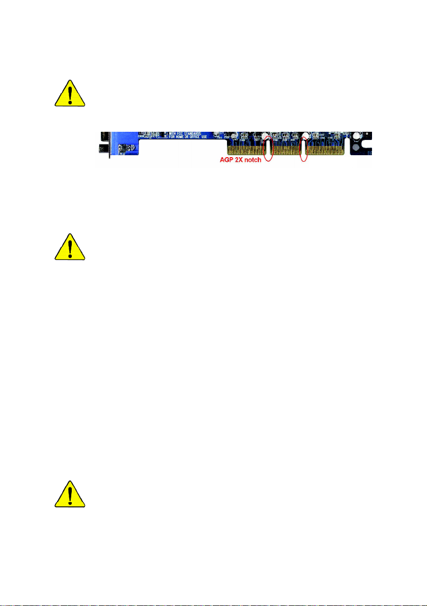
When you installing AGP card, please make sure the following notice
is fully understood and practiced. If your AGP card has "AGP 4X/8X
(1.5V) notch"(show below), please make sure your AGP card is AGP
4X/8X.
AGP 4X/8X notch
Caution: AGP 2X card is not supported by Intel® 845(GE/PE) / 845(E/G) /
850(E) / E7205 / 865(G/PE/P) / 875P. You might experience system
unable to boot up normally. Please insert an AGP Pro 4X/8X card.
Example 1: Diamond Vipper V770 golden finger is compatible with 2X/4X
mode AGP slot. It can be switched between AGP 2X(3.3V) or 4X(1.5V) mode
by adjusting the jumper. The factory default for this card is 2X(3.3V).
The GA-8KNXP Ultra-64 (or any AGP Pro 4X/8X only) motherboards might
not function properly, if you install this card without switching the jumper to 4X
(1.5V) mode in it.
Example 2: Some ATi Rage 128 Pro graphics cards made by "Power Color",
the graphics card manufacturer & some SiS 305 cards, their golden finger is
compatible with 2X(3.3V) / 4X(1.5V) mode AGP slot, but they support
2X(3.3V) only. The GA-8KNXP Ultra-64 (or any AGP Pro 4X/8X only)
motherboards might not function properly, If you install this card in it.
Note : Although Gigabyte's AG32S(G) graphics card is based on ATi Rage
128 Pro chip, the design of AG32S(G) is compliance with AGP 4X(1.5V)
specification. Therefore, AG32S(G) will work fine with Intel® 845(GE/PE) /
845(E/G) / 850(E) / E7205 / 865(G/PE/P) / 875P based motherboards.
Before you install PCI cards, please remove the Dual BIOS label from PCI
slots if there is one.
Page 2
The author assumes no responsibility for any errors or
omissions that may appear in this document nor does the
author make a commitment to update the information
contained herein.
Third-party brands and names are the property of their
respective owners.
Please do not remove any labels on motherboard, this may
void the warranty of this motherboard.
Due to rapid change in technology, some of the
specifications might be out of date before publication of
this booklet.
Page 3

Ausschla ger Weg 41, 1F, 20537 Hamburg, Germany
( description of the apparatus, system, installation to which it refers)
(reference to the specification under which con formity is declared)
in accordance with 89/336 EEC-EMC Directive
o EN 55011 Limits and methods of measurement
o EN 55013
o EN 55014 Limits and methods of measurement
o EN 55015 Limits and methods of measurement
o EN 55020
T EN 55022 Limits and methods of measurement
o DIN VDE 0855
o part 10
o part 12
T CE marking
o EN 60065
o EN 60335
of radio disturbance characteristics of
industrial,scientific and medical (ISM
high frequency equipment
Limits and methods of measurement
of radio disturbance characteristics of
broadcast receivers and associated
equipment
of radio disturbance characteristics of
household electrical appliances,
portable tools and similar electrical
apparatus
of radio disturbance characteristics of
fluorescent lamps and luminaries
Immunity from radio interference of
broadcast receivers and associated
equipment
of radio disturbance characteristics of
information technology equipment
Cabled distribution systems; Equipment
for receiving and/or distribution from
sound and television signals
The manufacturer also declares the conformity of above mentioned product
Safety requirements for mains operated
electronic and related apparatus for
household and similar general use
Safety of household and similar
electrical appliances
(Stamp)
with the actual required safety standards in accordance with LVD 73/23 EEC
Declaration of Conformity
We, Manufacturer/Importer
(full address)
G.B.T. Tec hnology Träding GMbH
declare that the product
Mother Board
GA-8KNXP Ultra-64
is in conformity with
o EN 61000-3-2*
T EN 60555-2
o EN 61000-3-3* Disturbances in supply systems cause
T EN 60555-3
T EN 50081-1
T EN 50082-1
o EN 55081-2
o EN 55082-2
o ENV 55104
o EN50091-2
(EC conformity marking)
o EN 60950
o EN 50091-1
Manufacturer/Importer
Date : Mar. 12, 2004
Disturbances in supply systems cause
by household appliances and similar
electrical equipment “Harmonics”
by household appliances and similar
electrical equipment “Voltage fluctuations”
Generic emission standard Part 1:
Residual commercial and light industry
Generic immunity standard Part 1:
Residual commercial and light industry
Generic emission standard Part 2:
Industrial environment
Generic emission standard Part 2:
Industrial environment
lmmunity requirements for household
appliances tools and similar apparatus
EMC requirements for uninterruptible
power systems (UPS)
Safety for information technology equipment
including electrical bussiness equipment
General and Safety requirements for
uninterruptible power systems (UPS)
Signature:
Name:
Timmy Huang
Timmy Huang
Page 4

DECLARATION OF CONFORMITY
Per FCC Part 2 Section 2.1077(a)
Responsible Party Name:
Add ress:
Phone/Fax No:
hereby declares that the product
Product Name: Motherboard
Model Nu mber: GA-8KNXP Ultra-64
Conforms to the follow ing specifications:
FCC Part 15, Subpart B, S ection 15.107(a) and Section 15.109(a),
Class B Digital Device
Supplementary Information:
This device complies with part 15 of the FCC Rules. Operation is
subject to t he following two conditions: (1) This device may not
cause harmful and (2) this device must accept any inference received,
including that may cause undes ired operation.
Representative Person’s Name:
Signature:
G.B.T. INC. (U.S.A .)
17358 Railroad Street
City of Indu stry, CA 91748
(818) 854-9338/ (818) 854-9339
ERIC LU
Eric Lu
Date:
Mar. 12, 2004
Page 5

GA-8KNXP Ultra-64
P4 Titan Series Motherboard
USER'S MANUAL
Pentium® 4 Processor Motherboard
Rev. 1001
12ME-8KNXPU64-1001
Page 6

Table of Content
English
Warning ...........................................................................................4
Chapter 1 Introduction .......................................................................5
Chapter 2 Hardware Installation Process ......................................... 11
Chapter 3 BIOS Setup .................................................................... 37
Features Summary................................................................................................ 5
GA-8KNXP Ultra-64 Motherboard Layout ......................................................... 8
Block Diagram ....................................................................................................... 9
Step 1: Install the Central Processing Unit (CPU) .........................................12
Step 1-1: CPU Installation ............................................................................ 12
Step 1-2: CPU Cooling Fan Installation .......................................................... 13
Step 2: Install Memory Modules .......................................................................14
Step 3: Install expansion cards ......................................................................... 17
Step 4: Install I/O Peripherals Cables ..............................................................18
Step 4-1: I/O Back Panel Introduction ............................................................ 18
Step 4-2: Connectors Introduction ................................................................. 20
The Main Menu (For example: BIOS Ver. : D4) ............................................ 38
Standard CMOS Features ................................................................................. 40
Advanced BIOS Features ................................................................................... 43
Integrated Peripherals ....................................................................................... 44
Power Management Setup ................................................................................ 49
PnP/PCI Configurations ...................................................................................... 51
PC Health Status .................................................................................................. 52
Frequency/Voltage Control ................................................................................ 54
Load Fail-Safe Defaults ...................................................................................... 56
- 2 -GA-8KNXP Ultra-64 Motherboard
Page 7

Load Optimized Defaults .................................................................................... 57
Set Supervisor/User Password .......................................................................... 57
Save & Exit Setup ................................................................................................. 58
Exit Without Saving ............................................................................................. 58
Chapter 4 Technical Reference ........................................................ 59
@ BIOSTM Introduction ........................................................................................ 59
Easy TuneTM 4 Introduction ............................................................................... 60
Dual Power System-Gold (DPS-Gold) Introduction ...................................... 61
Flash BIOS Method Introduction ......................................................................62
2- / 4- / 6- / 8- Channel Audio Function Introduction ..................................... 83
Jack-Sensing and UAJ Introduction ................................................................. 89
Xpress Recovery Introduction ........................................................................... 91
Chapter 5 Appendix ........................................................................ 95
English
- 3 -
Table of Content
Page 8

Warning
English
Computer motherboards and expan sion cards contain very delicate Integrated C ircuit (IC ) chip s. To
protect them against damage from static electricity, you should follow some precautions whenev er y ou
work on your computer.
Installing the motherboard to the chassis...
are no slots to attach the spacers, do not become alarmed you can still attach the spacers to the
mounting holes. Just cut the bottom portion of the spacers (the spacer may be a little hard to cut off, so
be careful of y our hands). In this way you can still attach the motherboard to the base without w orry ing
about short circuits. Sometimes y ou may need to use the plastic springs to isolate the screw from the
motherboard PCB surface, because the circuit wire may be near by the hole. Be car eful, don't let the
screw contact any prin ted circuit write or parts on the PC B that are near the fix ing hole, otherwise it
may damage the board or ca use board malfunctio ning.
1. Unplug your computer when working on the inside.
2. Use a grounded wrist strap befo re handling compu ter comp onents. If you do not have one,
touch both of your hands to a safely gro unded object or to a metal object, such as the power
supply case.
3. Hold components by the edges and try no t touch the IC chips, leads or con nectors, or other
components.
4. Place components on a grounded antistatic pad or on the bag that came with the co mponents
whenev er the com ponents are separated from the sy stem.
5. Ensure that the ATX pow er supply is switched off before you plug in or remove the ATX pow er
connector on the motherboard.
If the motherboard has mounting hol es, but they don't line up w ith the holes on the base and there
- 4 -GA-8KNXP Ultra-64 Motherboard
Page 9

Chapter 1 Introduction
Features Summary
CPU — Socket 478 for Intel® Pentium® 4 (Northwood, Prescott)
with HT Technology
— Intel® Pentium® 4 800/533/400MH z FSB
— 2nd cache depends on CPU
Chipset — North Bridge: Intel® 875P
— South Bridge: Intel® HR
Memory — 6 184-pin DDR DIMM sockets
— Supports Dual Channel DDR400/DDR333/DDR26 6 DIMM
— Supports 128MB/256MB/512M B/1G B unbuffered DRAM
— Supports up to 4GB DRAM (M ax)
— Supports only 2.5V DDR DIMM
— Supports 64bit ECC/non-ECC type DRAM integrity mode
Slots — 1 AGP slot supports 8X/4X(1.5V) mode
— 3 PCI slots support
— 2 64-Bit PCI-X slots
On-Board IDE — 2 IDE bus master (UDMA33/ATA66/ATA100) IDE ports for up to
4 ATAPI devices
— Can connect up to 4 IDE devices
On-Board Floppy — 1 Floppy port supports 2 FDD with 360K, 720K,1.2M, 1.44M and
2.88M bytes
On-Board Peripherals — 1 Parallel port supports Normal/EPP/EC P mode
— 2 Serial ports (COMA & C OM B)
— 8 USB 2.0/1.1 ports (4 x Rear, 4 x Front by cable)
— 1 IrDA connector for IR/CIR
— 1 Front Audio connector
(Note 1)
English
to be continued......
Due to chipset (Intel 875P) architecture limitation, a FSB 800 Pentium 4 processor will support
DDR400/DDR333/DDR266 memory module. A FSB 533 Pentium 4 process or w ill su pport
DDR333 and DDR266 m emory modu le. A FSB 400 Pentium 4 processo r w il l only support
DDR 266 memory m odule.
(Note 1) Due to standard PC architecture, a certain amount of memory is reserved for sy stem
usage and ther efore the actual memory size is less than the stated amount.
For example, 4 GB of memory size will instead be shown as 3.x x GB m emory
during system startup.
- 5 -
Introduction
Page 10

On-Board LAN — Builit in Intel® 82547 (KENAI II CSA) Chipset
English
On-Board Sound — Realtek ALC850 UAJ CODEC
Serial ATA — Controlled by HR
On-Board SCSI — 2 SCSI connectors in 320 M B/s per channel
Hardware Monitor — CPU/System/Power fan revolution detect
On-Board SATA RAID — Built in HR
Data transfer rate 10/100/1000 supp orted
— 1 RJ45 port
— Support Jack-Sensing
— Line Out / 2 front speaker
— Line In / 2 rear speaker(by s/w switch)
— Mic In / center& subwoofer(by s/w switch)
— SPDIF Out /SPDIF In
— CD_In
— Surround Back speaker (by optional Surround-Kit)
- 2 Serial ATA connectors (SATA0_SB/SATA 1_SB) in 15 0 MB/s
operation mode
— Controlled by SiI3114
- 4 Serial ATA connectors (SATA0_SII/SATA1_SII/SATA2_SII/
SATA3_S II) in 150 M B/s operation mode
— Controlled by Adaptec AIC- 7902W
— CPU temperature detect
— CPU warning temperature
— System voltage detect
— CPU/Sy stem/Pow er fan fail w arning
— CPU smart fan co ntrol
- Supports Disk striping (RAID0) or mirroring (RAID 1)
- Supports UDMA u p to 150 M B/sec
- Up to 2 SATA devices
- Only supports Windows 20 00/XP
— Built in Silicon Image Sil3114
- Supports Disk striping (RAID0) or DISK Mirroring (RAID1)
or striping+mirroring (RAID10)
- Supports UDMA u p to 150 M B/sec
- Up to 4 SATA Device
- supports Win 2000/XP/NT/98/Me
to be continued......
- 6 -GA-8KNXP Ultra-64 Motherboard
Page 11

On-Board SCSI RAID — Onboard Adaptec AIC-7902W chip
— Supports Disk striping (RAID0) or DISK Mirroring ( RAID1)
— Supports Ultra 320 (320 MB/sec per ch annel)
— Supports 4 hard disk drive s and 2 arrays per channel
I/O Control — ITE8712
PS/2 Connector — PS/2 Keyboard interface and PS/2 M ouse inte rface
BIOS — Licensed AWARD BIOS
— Supports Dual BIOS
— Supports Q-Flash
Additional Features — Supports CPU Du al Power System
— PS/2 Keyboard pow er on by pa ssword
— PS/2 Mouse pow er on
— External Modem w ake up
— STR(Suspend-To-RAM )
— Wake on LAN (WOL)
— AC Recovery
— Poly fuse for key board over-c urrent protection
— USB KB/Mouse w ake up from S3
— Supports @BIOS
— Supports EasyTune 4
Overclocking — Over C lock (CPU/ DDR/AGP) b y BIOS
— Over Voltage (CPU /DDR/AGP) by BIOS
Form Factor — 30.5cm x 24.4cm ATX size form factor, 6 layers PCB
English
"*" HT functionality requirement content :
Enabling the functionality of Hy per-Threading Technology for y our computer system requires all
of the follow ing platform components:
- CPU: An Intel® Pentium 4 Processor with HT Technology
- Chipset: An Intel® Chipset that supports HT Technology
- BIOS: A BIOS that supports HT Technology and has it enabled
- OS: An operation system that has optimizations for HT Technology
Please set the CPU host frequency in accordance with y our processor's specifications.
We don't recommend you to set the system bus frequency over the CPU's specification because
these specific bus frequencies are not the standard specifications for CPU, chipset and most of the
peripherals. Whether your sy stem can run under these specific bus frequencies properly will
depend on your hardware configurations, including CPU, Chipsets, Memory, Cards… etc.
- 7 -
Introduction
Page 12
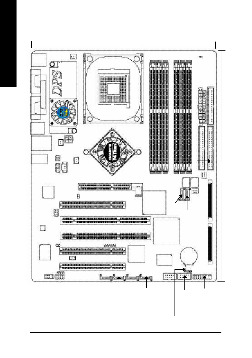
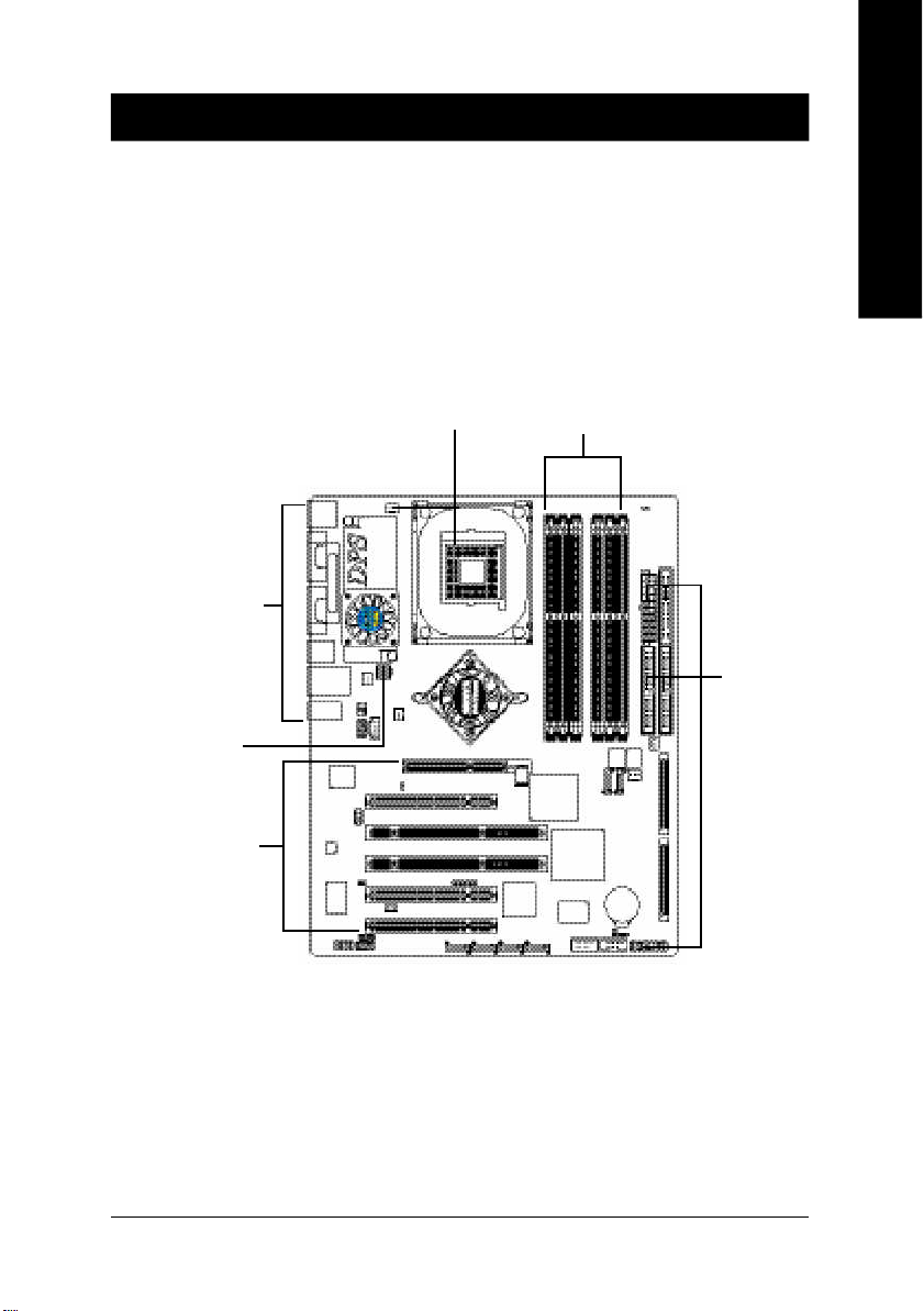
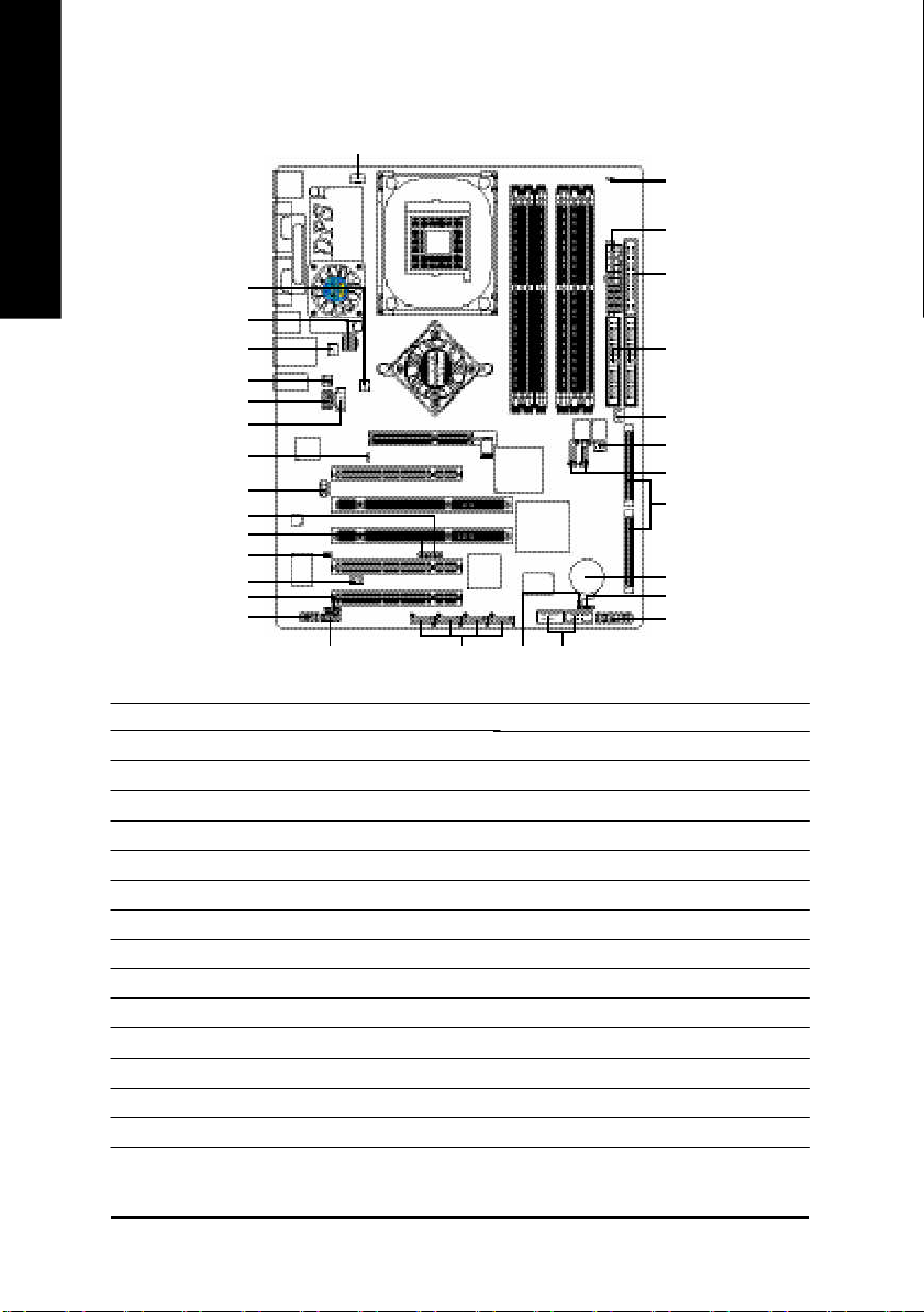
GA-8KNXP Ultra-64 Motherboard Layout
24.4 cm
English
KB_MS
R_USB
AUDIO
IR_CIR
COMA
LPT
COMB
USB
F_AUDIO
Intel
KENAI II
SUR_CEN
CODEC
LAN
64PCI1
64PCI2
PCI2
ITE8712
PCI3
CPU_FAN
ATX_12V
DPS_FAN
SPDIF_IO
NB_FAN
CD_IN
2X_DET
DUAL CHANNEL DDR
CI
WOL
SCSI_LED_C
INFO_LINK
Intel® 875P
P4 Titan
DDR 400+
M66EN1
SATA0_SII
SOCKET 478
PCIX1
AGP
PCI1
Sil3 114
SATA2_SII
DDR3
DDR1
DDR2
DDR4
DDR5
GA-8KNXP Ultra-64
BACKUP
BIOS
HR
SATA0_SB
SATA1_SB
Adap tec
AIC-7 902W
VT6202
F_USB2
BAT
DDR6
RAM_LED
ATX
IDE1
MAIN
BIOS
SYS_FAN
PWR_LED
FDD
IDE2
30.5 cm
PWR_FAN
SCSI 2
SCSI 1
SATA1_SII
- 8 -GA-8KNXP Ultra-64 Motherboard
SATA3_SII
F_USB1
CLR_CMOS
F_PANEL
Page 13
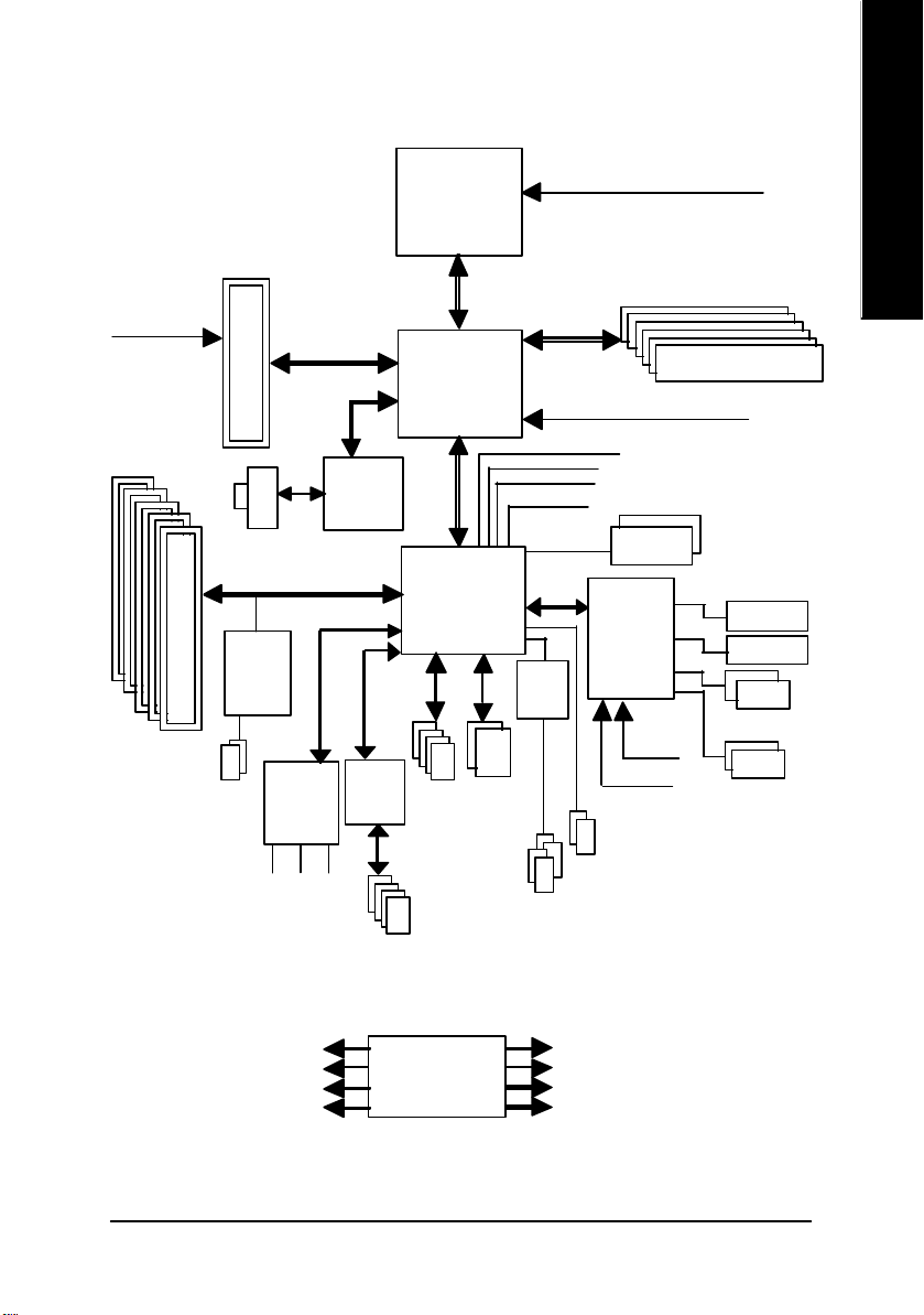
Block Diagram
English
AGPCLK
(66MHz)
3 PCI
2 PCI-X
AGP
4X/8X
RJ45
Adaptec
AIC-7902W
2 SCSI
AC97
CODEC
Intel
KENAI II
CSA
AC97 Link
VT6202
Pentium 4
Socket 478
CPU
Intel 875P
Intel
HR
ATA33/66/100
4 USB
IDE Channels
Ports
CPUCLK+/- (100/133/200MHz)
System Bus
800/533/400MHz
MCHCLK (100/133/200MHz)
66 MHz
48 MHz
LPC BUS
Sili com
Image
Sil3 114
200/333/400MHz
33 MHz
14.318 MHz
BIOS
ITE8712
24 MHz
33 MHz
2 Serial ATA
DDR RAM
Floppy
LPT Port
PS/2 KB/Mouse
2 COM Ports
MIC
PCICLK (33MHz)
USBCLK (48MHz)
14.318 MHz
33 MHz
LINE-IN
LINE-OUT
4 USB
Ports
CLK GEN
- 9 -
4 Serial ATA
CPUCLK+/- (100/133/200MHz)
AGPCLK (66MHz)
MCHCLK (100/133/200mHz)
ICH3V66 (66MHz)
Introduction
Page 14

English
- 10 -GA-8KNXP Ultra-64 Motherboard
Page 15
Chapter 2 Hardware Installation Process
To set up your computer, you must complete the following steps:
Step 1- Install the Central Processing Unit (CPU)
Step 2- Install memory modules
Step 3- Install expansion cards
Step 4- Install I/O Peripherals Cables
English
Step 1
Step 4
Step 4
Step 3
Congratulations! You have accomplished the hardware installation!
Turn on the power supply or connect the power cable to the power outlet. Continue with
the BIOS/software installation.
Step 2
Step 4
- 11 -
Hardware Installation Proc ess
Page 16
Step 1: Install the Central Processing Unit (CPU)
English
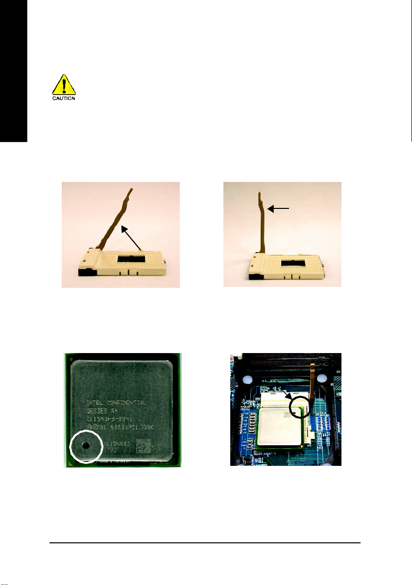
Step 1-1: CPU Installation
Before installing the processor, adhere to the following warning:
1. Please make sure the CPU type is supported by the motherboard.
2. If you do not match the CPU socket Pin 1 and CPU cut edge well, it will
cause improper installation. Please change the insert orientation.
Angling the
rod to 65
1. Angling the rod to 65-degree maybe
feel a kind of tight , and then continue
pull the rod to 90-degree when a noise
"cough" made.
0
Pin1 indicator
3. CPU Top View
Socket
Actuation
Lever
2. Pull the rod to the 90-degree directly.
Pin1 indicator
4. Locate Pin 1 in the socket and
look for a (golden) cut edge on the
CPU upper corner. Then insert
the CPU into the socket.
GA-8KNXP Ultra-64 Motherboard
- 12 -
Page 17
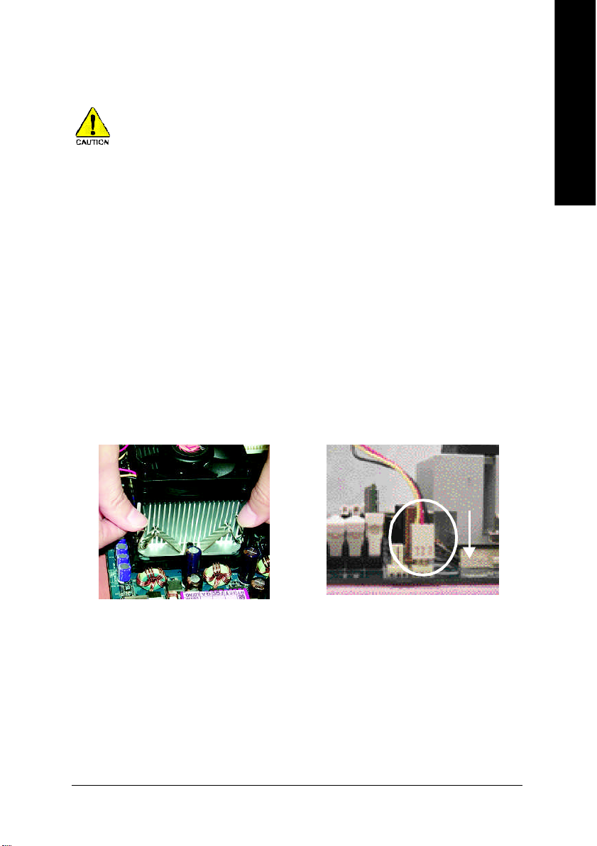
Step 1-2: CPU Cooling Fan Installation
Before installing the CPU cooling fan, adhere to the following warning:
1. Please use Intel approved cooling fan.
2. We recommend you to apply the thermal tape to provide better heat
conduction between your CPU and cooling fan.
(The CPU cooling fan might stick to the CPU due to the hardening of
the thermal paste. During this condition if you try to remove the cool-
ing fan, you might pull the processor out of the CPU socket alone with
the cooling fan, and might damage the processor. To avoid this from
happening, we suggest you to either use thermal tape instead of
thermal paste, or remove the cooling fan with extreme caution.)
3. Make sure the CPU fan power cable is plugged in to the CPU fan
connector, this completes the installation.
Please refer to CPU cooling fan user's manual for more detail
installation procedure.
English
1. Fasten the cooling fan supporting-
base onto the CPU socket on the
motherboard.
- 13 -
2. Make sure the CPU fan is plugged
to the CPU fan connector, than
install complete.
Hardware Installation Proc ess
Page 18
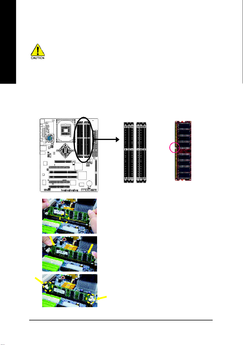
Step 2: Install Memory Modules
English
The motherboard has 6 dual inline memory module (DIMM) sockets. The BIOS will automatically
detects memory type and size. To install the memory module, just push it vertically into the DIMM
socket. The DIMM module can only fit in one direction due to the notch. Memory size can vary
between sockets.
Before installing the memory modules, adhere to the following warning:
1. When RAM_LED is ON, do not install / remove DIMM from socket.
2. Please note that the DIMM module can only fit in one direction due to
the one notch. Wrong orientation will cause improper installation.
Please change the insert orientation.
Notch
DDR
GA-8KNXP Ultra-64 Motherboard
1. The DIMM socket has a notch, so the DIMM me mory
modu le can only fit in one direction.
2. Insert the DIMM m emory m odule vertically into the DIMM
socke t. Then pu sh it down.
3. Close the plastic clip at both edges of the DIMM sockets to
lock the DIMM m odule.
Rever se the ins tallation steps when you wish to remo ve
the DIMM m odule.
- 14 -
Page 19

DDR Introduction
Establ ished o n the e xisting SDRAM infrastruc ture, DDR (Do uble Data Rate) mem ory is a high
perform ance and cost-effective so lution that allows eas y adoption for m emo ry vend ors, OEMs, and
system integrators.
DDR memory is a great evolutionary solution for the PC industry that builds on the existing
SDRAM architecture, yet make the awesome advances in solving the system performance bottleneck
by doubling the memory bandwidth. Nowadays, with the highest bandwidth of 3.2GB/s of DDR400
memory and complete line of DDR400/333/266/200 memory solutions, DDR memory is the best
choice for building high performance and low latency DRAM subsystem that are suitable for servers,
workstations, and full range of desktop PCs.
Dual Channel DDR:
GA-8K NXP Ultra-64 suppo rts Dual Channel Technolog y.
When D ual Channel Techno logy is activa ted, the bandwidth of m em ory bus will be double the or iginal
one, with the fastest spee d at 6.4 GB/s DDR 400.
GA-8K NXP Ultra-6 4 incl udes six DIMM slots, and each Cha nnel h as 3 DIM Ms as following:
Chann el A : D IMM 1, 2, 3
Chann el B : D IMM 4, 5, 6
Belo w are the explana tions:
1. One, three, or five DD R mem ory modul es are in stalled: The Dual C hannel Technol ogy
will not ope rate when one , three, or five DDR me mory m odules are ins talled and they
will only work a s Sin gle Chann el.
2. Two DDR mem ory modul es are i nstalled (the sam e mem ory size and type): The D ual
Chan nel Technolog y will operate when two DDR m em ory modu les are inserted i ndi-
viduall y into Channel A a nd Channe l B (DIMM 1 pairs up with DIMM 4, D IMM 2, 5 and
DIMM 3, 6). However, if the two DDR mem ory m odules are inserted into the sam e
Channe l (DIMM 1,2,3 or DIMM 4,5,6) then Dual Ch annel Technology will not operate.
3. Three or five DDR memory m odules are installed: Plea se note that The Du al Channel
Technology will not operate when three or five DDR m em ory module s are installed; part
of them will not be detected.
4. If four DDR memory modules a re installed (two pairs of DDR m emory m odules with the
sam e m em ory size and type): The Dual C hannel Technology will operate when a pair
of DDR m emory m odules are inserted into DIMM 1, 4 an d another pair into DIM M 2,5.
English
- 15 -
Hardware Installation Proc ess
Page 20

English
The foll owing tables include all mem ory-installed c ombina tion types:
(Plea se note that those types no t in the table s will not b oot up.)
l Figure 1: Dual Channel Techno logy (DS: Double Side, SS: Single Side)
l Figure 2: Don't operate Dual Channel Technology (DS: Dou ble Side, SS: Single Side)
5. If six DDR memo ry modules are ins talled: To activate the Dual Channel Technology and
to make the size of each DDR m em ory m odul e detected, please use s ix DDR mem ory
mo dules with identical s ize and type and insert them into the six DIM Ms following the
sequ ence below:
DIMM 1: Double or Single Side
DIMM 2: Single S ide
DIMM 3: Single S ide
DIMM 4: Double or Single Side (if DIMM1 is inserted a double-side module, then DIIMM 4
mus t also be inserted a double-sid e one.)
DIMM 5: Single S ide
DIMM 6: Single S ide
DIMM 1 DIMM 2 DIMM 3 DIMM 4 DIMM5 DIMM6
DS/SS X X DS/SS X X
2 me mory modules
4 me mory modules
6 me mory modules
1 memory module
2 me mory modules
3 me mory modules
X DS/SS X X DS/SS X
X X DS/SS X X DS/SS
DS/SS DS/SS X DS/SS DS/SS X
DS/SS SS SS DS/SS SS SS
DIMM 1 DIMM 3 DIMM5
DS/SS X X
X DS/SS X
X X DS/SS
DS/SS DS/SS X
DS/SS SS SS
GA-8KNXP Ultra-64 Motherboard
- 16 -
Page 21
Step 3: Install expansion cards
1. Read the related expansion card's instruction document before install the expansion card into the
computer.
2. Remove your computer's chassis cover, screws and slot bracket from the computer.
3. Press the expansion card firmly into expansion slot in motherboard.
4. Be sure the metal contacts on the card are indeed seated in the slot.
5. Replace the screw to secure the slot bracket of the expansion card.
6. Replace your computer's chassis cover.
7. Power on the computer, if necessary, setup BIOS utility of expansion card from BIOS.
8. Install related driver from the operating system.
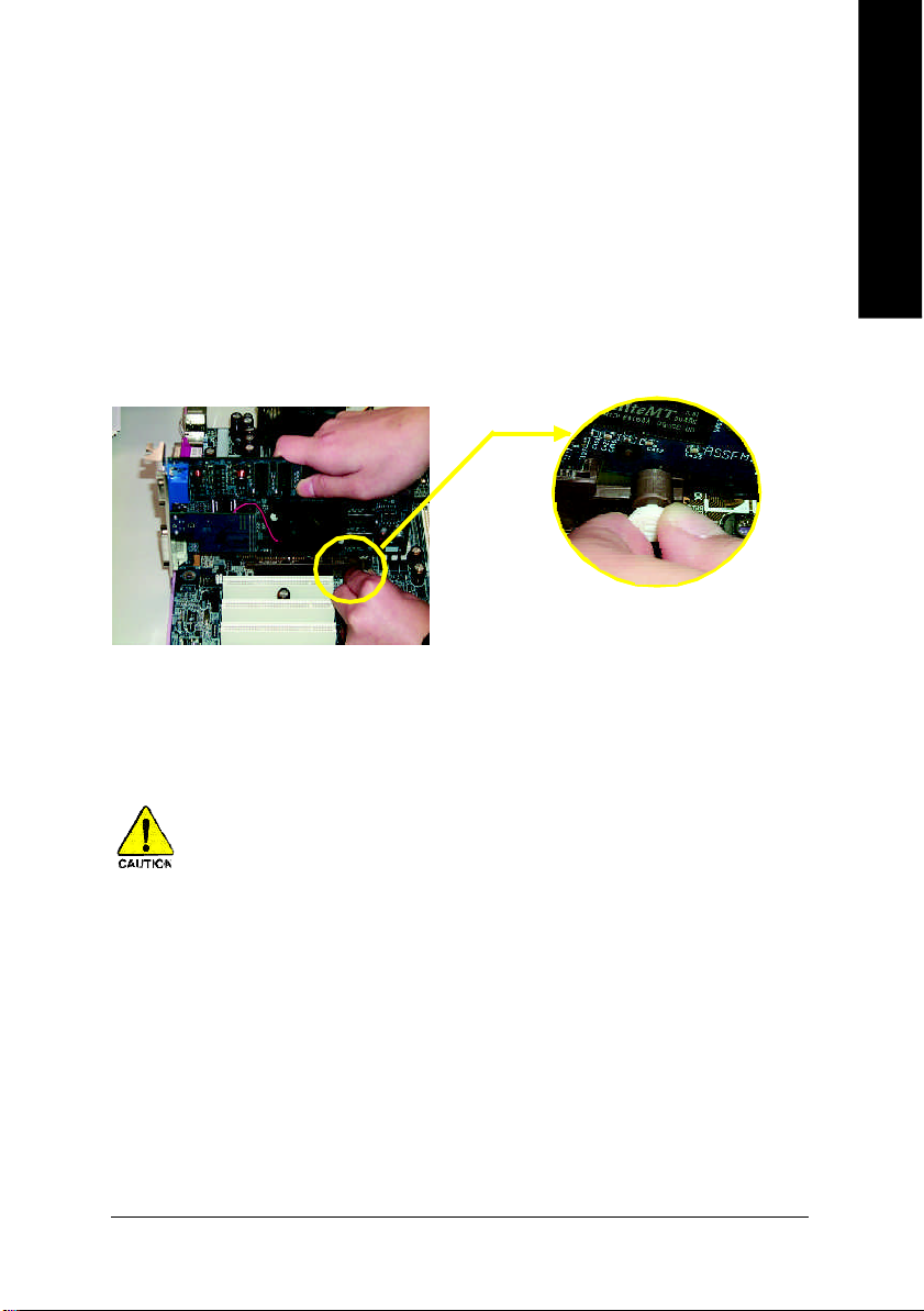
Please ca refully pull out the sm all white- drawable
bar at the end of the AGP slot when you try to install/
AGP Card
Uninstall the AGP card. Please align the AGP c ard
to the onbo ard AGP slot and press firm ly down on
the slot .Make sure your AGP card is locked by the
sm all white- drawabl e bar.
English
When an AGP 2x (3.3V) c ard is installed the 2X_D ET will light up, indicating a non-
supported graphics ca rd is inserted. Informing users that system might not boot up norm ally
due to A GP 2x (3.3V) is not suppor ted by the chipset.
- 17 -
Hardware Installation Proc ess
Page 22
Step 4: Install I/O Peripherals Cables
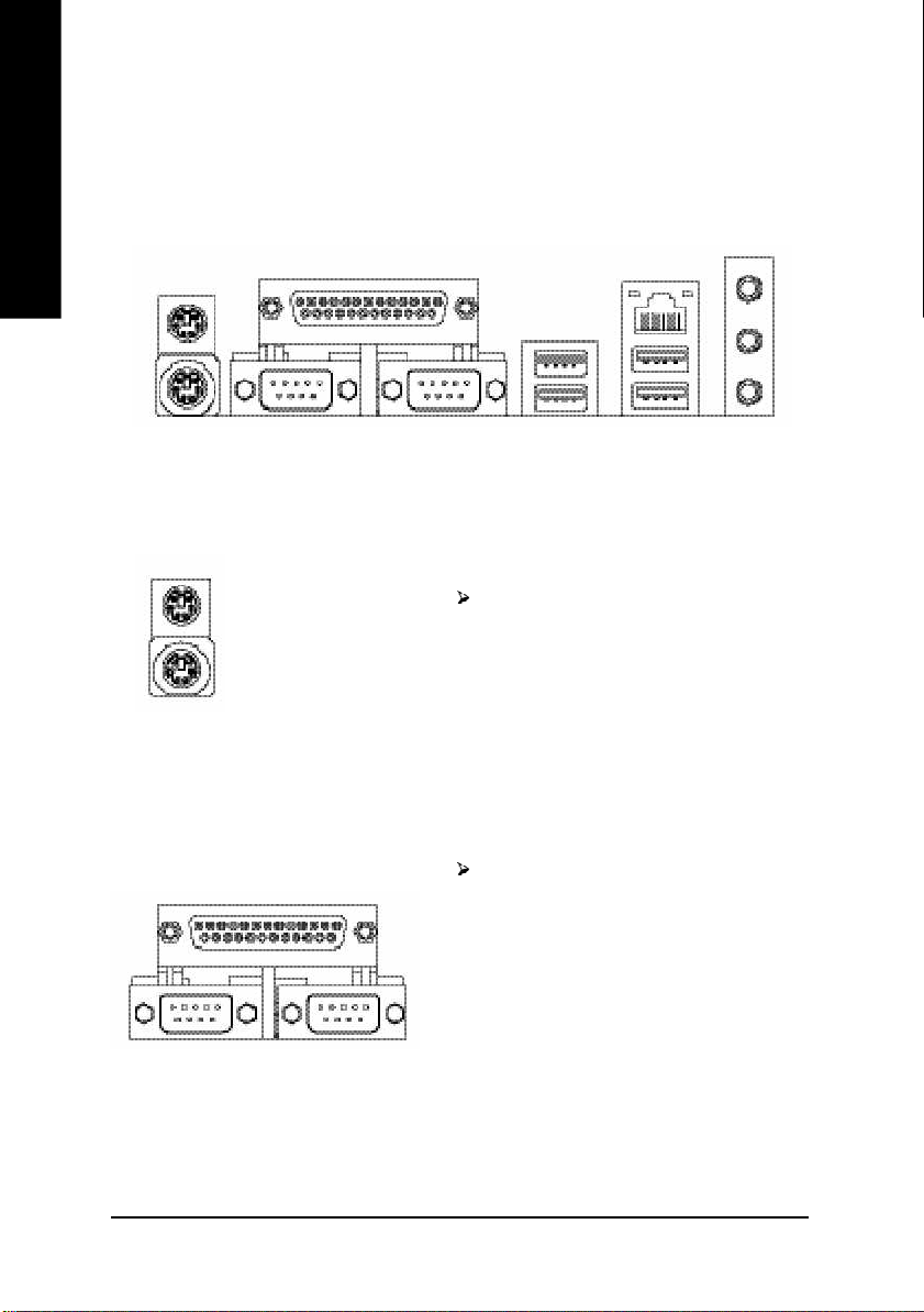
Step 4-1: I/O Back Panel Introduction
English
u
v
w
u PS/2 Keyboard and PS/2 Mouse Connector
PS/2 Mouse Connector
(6 pin Female)
PS/2 Keyboard Connector
(6 pin Female)
This connector supports standard PS/2
keyboard and PS/2 mouse.
v Parallel Port, Serial Port and VGA Port (LPT/COMA/COMB)
Parallel Port
(25 pin Female)
This connector supports 2 standard COM ports
and 1 Parallel port. Device like printer can be
connected to Parallel port; mouse and modem
etc can be connected to Serial ports.
y
x
COMA CO MB
Serial Port (9 pin Male)
GA-8KNXP Ultra-64 Motherboard
- 18 -
Page 23
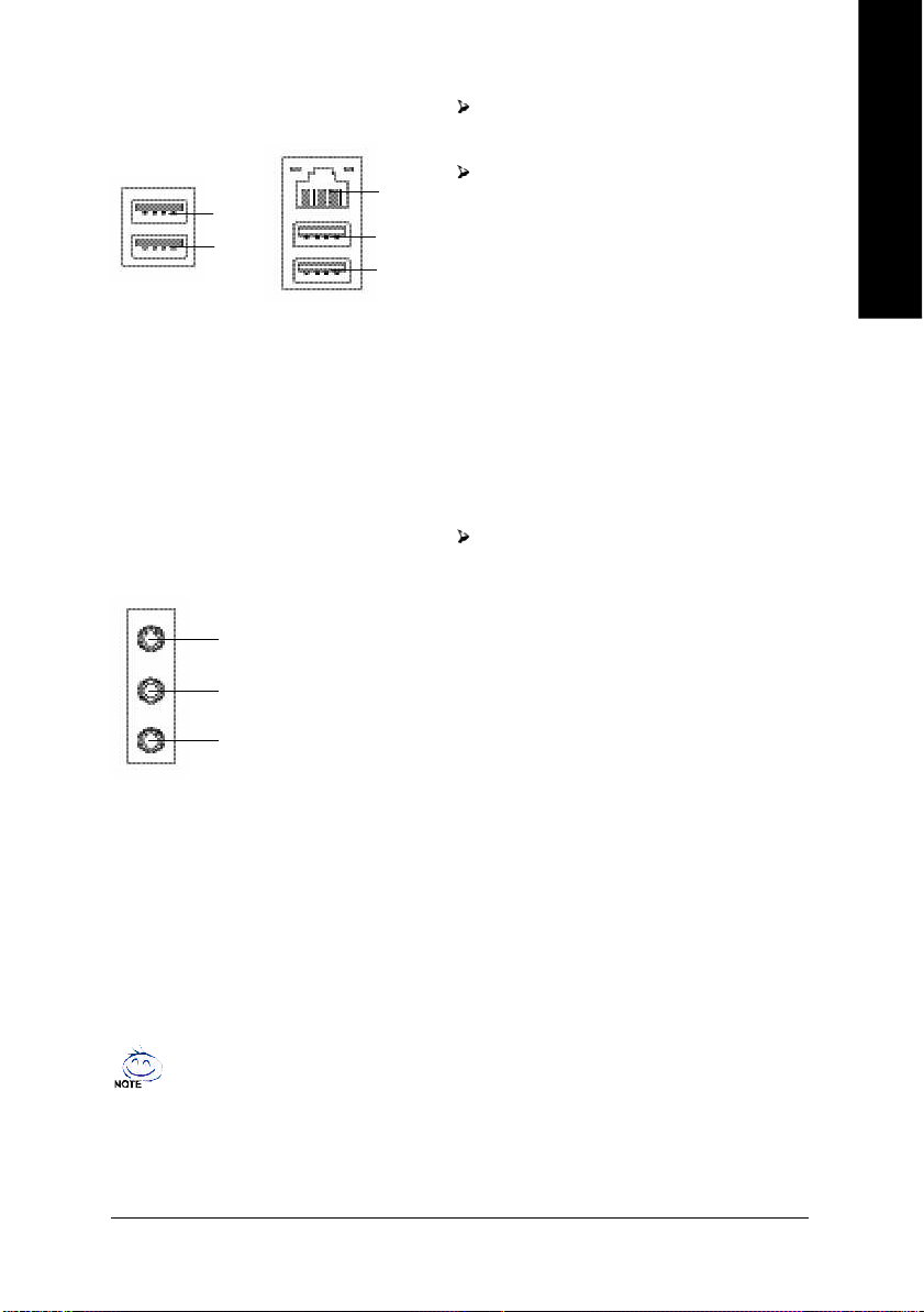
w/x USB / LAN Connector
USB 0
USB 1
LAN
USB 2
USB 3
LAN is fast Ethernet with 10/100/1000 Mbps
speed.
Before you connect your device(s) into USB
connector(s), please make sure your
device(s) such as USB keyboard,mouse,
scanner, zip, speaker..etc. Have a standard
USB interface. Also make sure your OS
supports USB controller.
If your OS does not support USB controller,
please contact OS vendor for possible patch
or driver upgrade. For more information
please contact your OS or device(s) vendors.
English
y Audio Connectors
Line In(Rear Speaker)
Line Out(Front Speaker)
MIC In(Center and Subwoofer)
If you want the detail information for 2-/4-/6-/8-channel audio setup
installation, please refer to page 83.
After install onboard audio driver, you may
connect speaker to Line Out jack,
microphone to MIC In jack. Devices like
CD-ROM, walkman etc. can be connected
to Line-In jack.
Please note:
You are able to use 2-/4-/6-/8-channel audio
feature by S/W selection.
If you want to enable 8-channel function you
can refer to page 30, and contact your
nearest dealer for optional SUR_CEN cable.
- 19 -
Hardware Installation Proc ess
Page 24
Step 4-2: Connectors Introduction
English
3
16
2
6
1
7
20
18
21
17
19
29
28
25
26
13
23
24
11
1) ATX_12V
2) ATX
3) CPU_FAN
4) SYS_FAN
5) PWR_FAN
6) NB_FAN
7) DPS_FAN
8) FDD
9) IDE1 / IDE2
10) SATA0_SB / SATA1_SB
11) SATA0_SII/SATA1 _SII/SATA2_SII/SATA3_S II
12) SCSI 1 / SCSI 2
13) SCSI_LED_C
14) PWR_LED
15) F_PANEL
22
27
16) RAM_LED
17) 2X_DET
18) F_AUDIO
19) SUR_CEN
20) SPDIF_IO
21) CD_IN
22) F_USB1 / F_USB2
23) IR_CIR
24) INFO_LINK
25) C I
26) WOL
27) CLR_CMOS
28) M66EN1
29) PCIX1
30) BAT
8
9
5
4
10
12
30
14
15
GA-8KNXP Ultra-64 Motherboard
- 20 -
Page 25
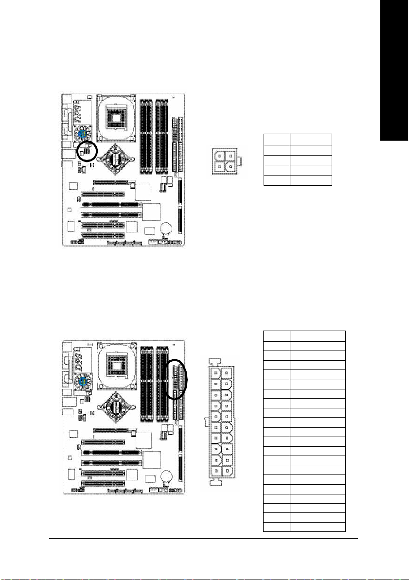
1) ATX_12V (+12V Power Connector)
This c onnector (ATX_12 V) supp lies the CPU operation voltage (Vcore ).
If this "ATX_1 2V connec tor" is no t connected, sy stem c annot boot.
English
1
3
2
4
Pin No. Definition
1 GND
2 GND
3 +12V
4 +12V
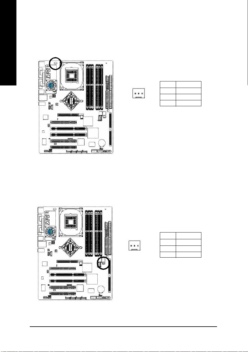
2) ATX (ATX Power)
AC p ower co rd shou ld o nly be connected to your power sup ply u nit after ATX po wer cab le and
other rela ted devices ar e firmly connected to the m ainboard.
Pin No . De finition
1 3.3V
2 3.3V
11
20
- 21 -
1
10
3 GND
4 VCC
5 GND
6 VCC
7 GND
8 Powe r Good
9 5V SB (stand by +5V)
10 +12V
11 3.3V
12 -12V
13 GND
14 PS_O N(soft on/off)
15 GND
16 GND
17 GND
18 -5V
19 VCC
20 VCC
Hardware Installation Proc ess
Page 26
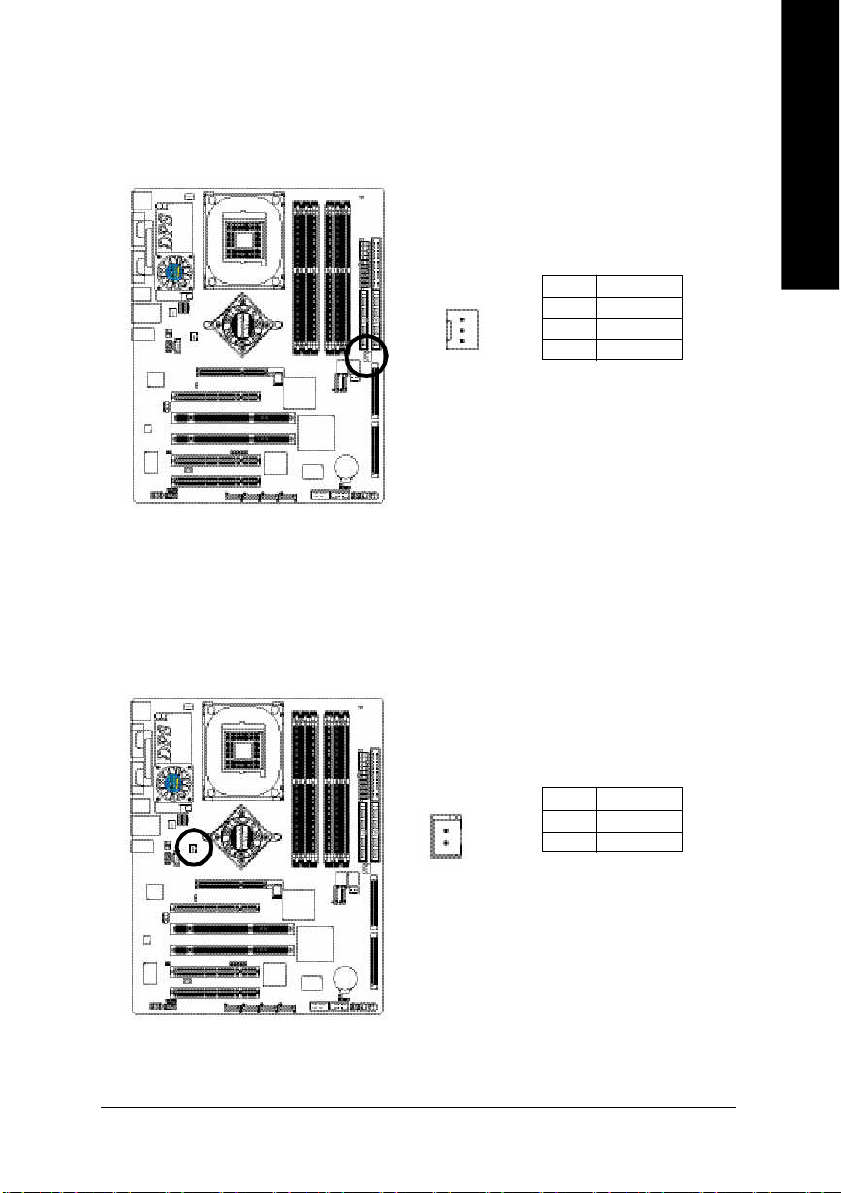
3) CPU_FAN (CPU Fan Connector)
English
4) SYS_FAN (System Fan Connector)
Pleas e note, a proper ins tallation of the CPU cooler is essential to prevent the CPU from running
unde r abnor mal condi tion or dama ged by overhea ting. T he CPU fan connector supports Max.
current up to 600 m A.
Pin No. Definition
1
This connec tor al lows you to li nk with the cool ing fan on the system case to lower the system
temperature.
1 GND
2 +12V
3 Sense
GA-8KNXP Ultra-64 Motherboard
- 22 -
Pin No. Definition
1
1 GND
2 +12V
3 Sense
Page 27
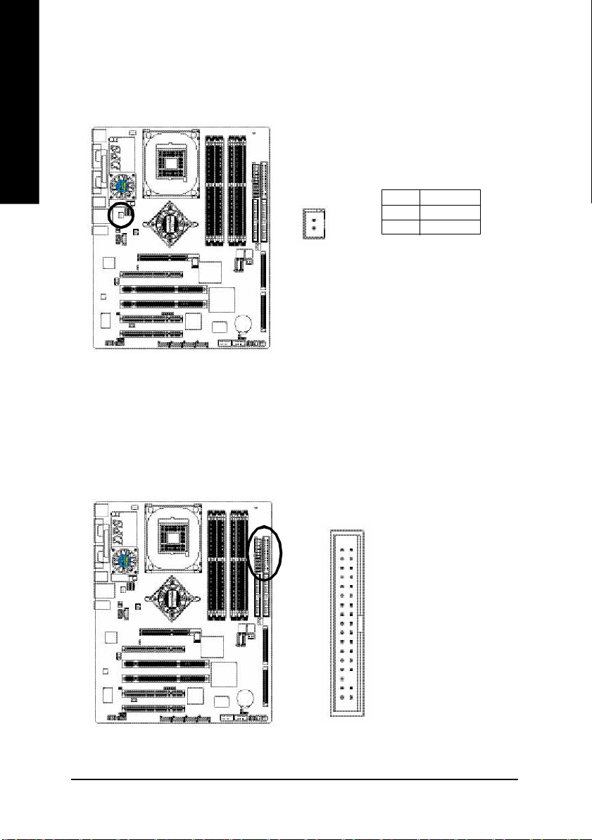
5) PWR_FAN (Power Fan Connector)
Thi s co nnector allows you to lin k with the coo ling fan on the s ystem case to lower the s ystem
temperature.
English
1
Pin No. Definition
1 GND
2 +12V
3 Sense
6) NB_FAN (Chip Fan Connector)
If you installed wrong direction , the c hip fan will not work . Som etimes will dama ge the chip fan.
(Usu ally bl ack cable i s GN D)
1
Pin No. Definition
1 VCC
2 GND
- 23 -
Hardware Installation Proc ess
Page 28
7) DPS_FAN (DPS Fan Connector)
English
If you installed wrong dir ection, the DPS fan will not work. Som etimes will damag e the D PS fan.
(Usu ally bl ack cable i s GN D)
1
Pin No. Definition
1 VCC
2 GND
8) FDD (Floppy Connector)
Pleas e connect the floppy drive ribbon cables to FD D. It supports 36 0K, 1.2M , 720K, 1.44M a nd
2.8 8M b ytes flo ppy di sk typ es.
The r ed stripe of the ribbon ca ble mu st be the sam e side with the Pin1.
34
33
GA-8KNXP Ultra-64 Motherboard
- 24 -
2
1
Page 29
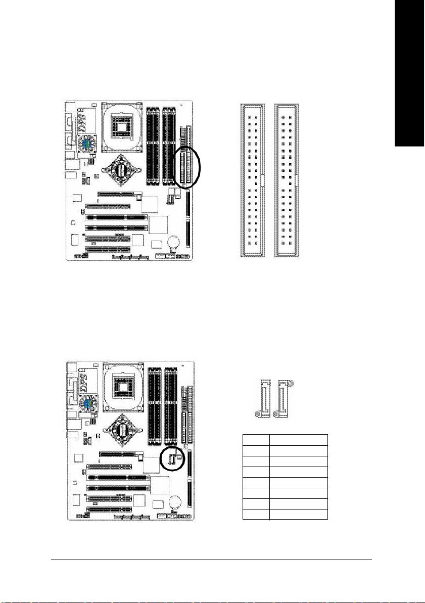
9) IDE1 / IDE2 (IDE1 / IDE2 Connector)
Impor tant Notice:
Pleas e connect first hard disk to IDE1 and c onnect CD-ROM to IDE2.
The r ed stripe of the ribbon ca ble mu st be the sam e side with the Pin1.
English
3940
12
IDE2
IDE1
10) SATA0_SB / SATA1_SB (Serial ATA Connector)
You can co nnect the Seria l ATA device to this c onnector, it provides y ou high speed transfer rates
(150M B/sec). If you wish to use RAID func tion, pl ease note that these two Seria l ATA connectors
just sup port RAID 0 or RAID 1 and o nly com patible with W in 2000/X P.
1
1
SATA0_SB
Pin No. Definition
1 GND
2 TXP
3 TXN
4 GND
5 RXN
6 RXP
7 GND
7
SATA1_SB
7
- 25 -
Hardware Installation Proc ess
Page 30
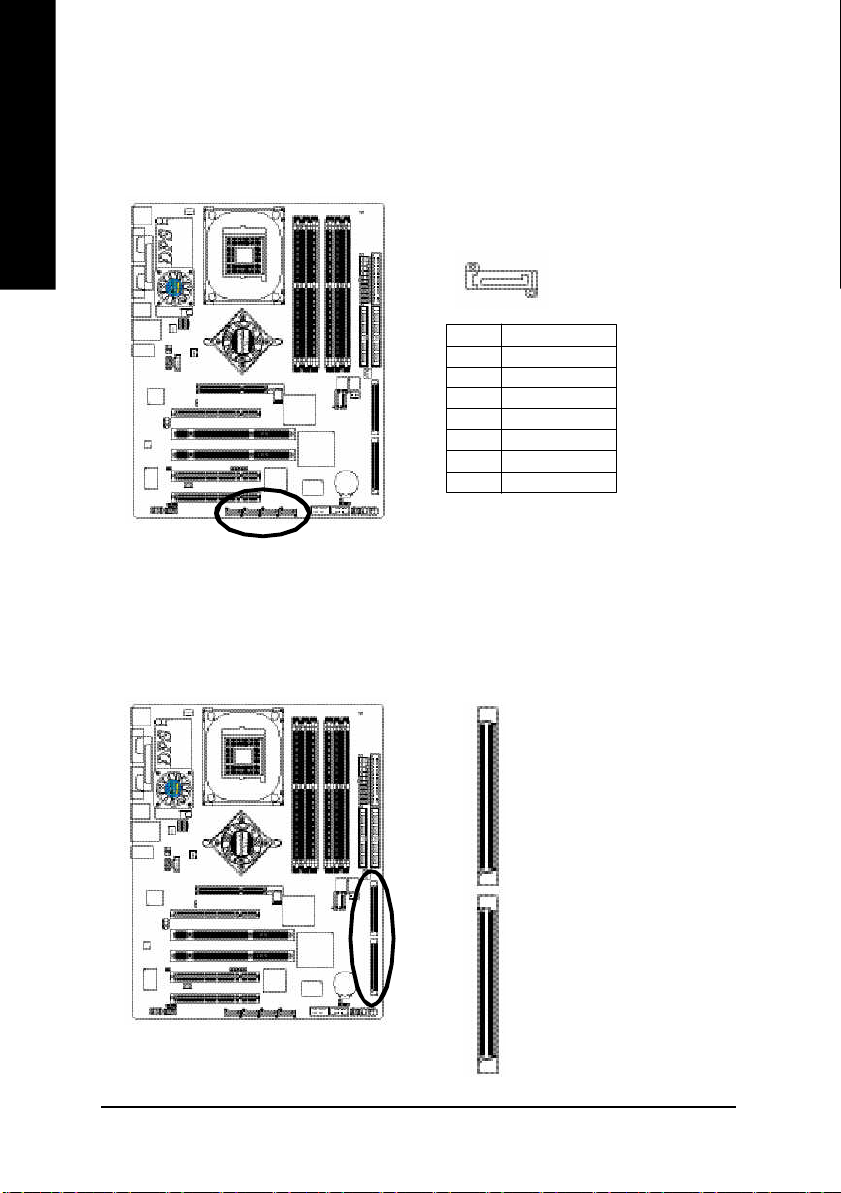
11) SATA0_SII / SATA1_SII / STAT2_SII / SATA3_SII (Serial ATA Connector)
English
You can co nnect the Seria l ATA device to this c onnector, it provides y ou high speed transfer rates
(150M B/sec). If you wish to use RAID func tion, pl ease note that these two Seria l ATA connectors
just sup port RAID 0 or RAID 1 and RAID 1 0.
1
Pin No. Definition
1 GND
2 TXP
3 TXN
4 GND
5 RXN
6 RXP
7 GND
7
12) SCSI 1 / SCSI 2 (RAID / SCSI Connector)
You can conn ect all maj or SCSI peri pher als to this co nnec tor. U ltra32 0 S CSI techno logy is
com patible with Ultra160, U ltra2, Ultra W ide and all other previou s-generation SCSI device s. The
data transfer rate is up to 320 M B/sec p er ch annel. On ly com patible with W in 2000/X P/NT.
SCSI 2
GA-8KNXP Ultra-64 Motherboard
SCSI 1
- 26 -
Page 31

13) SCSI_LED_C (SCSI Indicative LED Connector)
You can co nnect the SCSI indica tive LED of yo ur ch assis to this connector, whic h can indica te
whether the SC SI device is active or no t.
Pin No. Definition
1 LED+
2 LED-
1
3 LED4 LED+
14) PWR_LED
PWR_ LED is con nect with the sy stem po wer in dicator to i ndicate whether the sys tem is on/ off.
It will bl ink when the sy stem enters susp end mode . If you use du al color LE D, power LED will turn
to another colo r.
English
- 27 -
1
Pin No. Definition
1 MPD+
2 MPD-
3 MPD-
Hardware Installation Proc ess
Page 32

15) F_PANEL (2 x 10 pins Connector)
English
Plea se conne ct the po wer LED, PC spe aker, reset switch and po wer switch e tc. of you r chass is
front panel to the F_PANEL con nector ac cording to the pin ass ignmen t below.
Messa ge L ED/
Po wer/
Slee p LED
1 1
2
1
1
IDE H ard Disk Acti ve LE D
Sof t Po wer
Connect or
MSG+
MSG-
HD-
HD+
Res et Swi tch
PW+
RES-
PW-
1
RES+
NC
Speak er Co nnector
SPEAK+
SPEAK-
1
2 0
1 9
HD (IDE Hard Disk Active LED) Pin 1: LED anode(+)
(Blue) Pin 2: LED cathode(-)
SPEAK (Speaker Connector) Pin 1: V CC(+)
(Amber) Pin 2- Pin 3: NC
Pin 4: Data(-)
RES (Reset Switch) Open: Normal Operation
(Green) Close: Reset Hardware System
PW (Soft Power Connector) Open: Normal Operation
(Red) Close: Power On/Off
MSG(Message LED/ Power/ Sleep LED) Pin 1: LED anode(+)
(Yellow) Pin 2: LED cathode(-)
NC (Purple) N C
GA-8KNXP Ultra-64 Motherboard
- 28 -
Page 33

16) RAM_LED
Do not rem ove me mory m odules while RAM _LED is on. It might cause short or other unexpec ted
dam ages d ue to the stand by vo ltage. Re move mem ory m odules onl y when AC power cord is
disco nnected.
English
_
+
17) 2X_DET
When an AGP 2X (3. 3V) c ard is ins talled the 2X_DET will l ight up, ind icating a non -suppo rted
graphi cs card is inserted. Informing users that system might no t boot up norma lly due to AGP 2X
(3.3V ) is n ot supported b y the chi pset.
+
_
- 29 -
Hardware Installation Proc ess
Page 34

18) F_AUDIO (Front Audio Connector)
English
19) SUR_CEN (Surround Center Connector)
If you want to use Fr ont Audio c onnector, y ou m ust rem ove 5-6, 9-10 Jumpe r.
In order to utilize the front audio header, your chassis m ust have front audio connector. Also pl ease
mak e sure the pin assigm ent on the cable is the sam e as the pin assig ment on the MB h eader. To
find ou t if the chass is you are buy ing s upport front audi o con nector, ple ase contact your de aler.
Plea se note, you ca n ha ve the a lternative o f using front audio conn ector or of us ing r ear aud io
conn ector to pl ay soun d.
Pin No. Definition
1 MIC
2 GND
3 REF
10 9
2
1
4 Power
5 Front Audio (R)
6 Rear Audio (R)
7 Reserved
8 No Pin
9 Front Audio (L)
10 Rear Audio (L)
Pleas e contact y our neare st dealer for optional SUR_CEN c able.
GA-8KNXP Ultra-64 Motherboard
- 30 -
Pin No. Definition
1 SUR OUTL
8
7
12
2 SUR OUTR
3 GND
4 No Pin
5 CENTER_OUT
6 BASS_OUT
7 AUX_L
8 AUX_R
Page 35

20) SPDIF_IO (SPDIF In/Out Connector)
The S PDIF output is capable o f providi ng digital audio to external spe akers or compre ssed AC3
data to an externa l Dolb y Di gital De coder. Use this feature on ly whe n your stere o system has
dig ital inp ut fun ction. Be ca reful with th e pol arity of the SPDIF _IO c onne ctor. Chec k the pi n
assig nment care fully while y ou connec t the SPDIF cable, i ncorrect con nection between the cable
and co nnector will m ake the device unable to work or eve n damag e it. For o ptional SPDIF cabl e,
pleas e contact you r loc al deale r.
English
21) CD_IN (CD In Connector)
Connec t CD-ROM or DVD-ROM audio out to the connector.
5
162
1
Pin No. Definition
1 VCC
2 No Pin
3 SPDIF
4 SPDIFI
5 GND
6 GND
Pin No. Definition
1 CD-L
2 GND
3 GND
4 CD-R
- 31 -
Hardware Installation Proc ess
Page 36

22) F_USB1 / F_USB2 (Front USB Connector, Yellow)
English
23) IR_CIR
Be ca reful with the p olarity of the front USB connector . Check the pi n assign ment carefully whi le
you con nect the front USB cable , incorrect conne ction between the ca ble and connector will m ake
the dev ice u nable to work or even damag e it. Fo r optional front USB cable, p lease contact your
local d ealer.
Pin No. Definition
1 Power
2
1 9
10
2 Power
3 USB Dx-
4 USB Dy-
5 USB Dx+
6 USB Dy+
7 GND
8 GND
9 No Pin
10 NC
Ma ke sur e the p in 1 on the IR dev ice is aling with pin o ne the connector. To enable the IR/C IR
function on the board, you are r equired to purchase a n option IR/C IR module. To use IR function
on ly, plea se con nect IR m odule to P in1 to Pin 5. Be care ful with the pol arity of the IR/CIR
con nector. Ch eck the pin as signm ent careful ly whil e y ou c onnec t the IR/ CIR c able, in correc t
connection be tween the cable and c onnector will make the device unable to work or even dam age
it. For optional IR/CIR cable , plea se contact yo ur loc al deale r.
GA-8KNXP Ultra-64 Motherboard
- 32 -
6 10
1 5
Pin No. Definition
1 VCC
2 NC
3 IRRX
4 GND
5 IRTX
6 NC
7 CIRRX
8 +5VSB
9 CIRTX
10 NC
Page 37

24) INFO_LINK
This c onnector allows yo u to connec t some externa l devices to pr ovide y ou extra function. Che ck
the pin a ssignm ent while y ou c onnec t the ex ternal device cab le. P lease contact your neares t
deale r for optional external de vice cabl e.
Pin No. Definition
1 SMBCLK
102
1
9
2 VCC
3 SMBDATA
4 GPIO
5 GND
6 GND
7 No Pin
8 NC
9 +12V
10 +12V
25) CI (CASE OPEN)
This 2- pin connector allo ws your system to enable or di sable the "Case Op en" item in BIOS, if the
system case beg in r em ov e.
English
- 33 -
1
Pin No. Definition
1 Signal
2 GND
Hardware Installation Proc ess
Page 38

26) WOL (Wake On LAN)
English
27) CLR_CMOS (Clear CMOS)
This connector allo ws the rem ote servers to m anage this system via your network adap ter which
sup ports WOL. Be careful with the po larity of the WOL conn ector. Check the p in assig nm en t
carefully while you connect the WOL c able, in correct connection between the cabl e and connec tor
will m ake the device u nable to work or eve n dam age it. Fo r option al WOL ca ble, p lease co ntact
your local dealer.
Pin No. Definition
1
You ma y clear the CMOS data to its default val ues by this j umper. To clea r CMOS, temporari ly
shor 1- 2 pin. Default doesn' t include the "Shunter" to prevent from im proper use this jump er.
1 +5V SB
2 GND
3 Signal
GA-8KNXP Ultra-64 Motherboard
- 34 -
Open: Norm al
1
Short: Clear CMOS
1
Page 39

28/29) M66EN1/PCIX1
30) BATTERY
1
1
M66EN1
M66EN1 PCIX1 Function
1-2 c lose 1-2 close PCI-X Mode (Default)
1
M66EN1
M66EN1 PCIX1 Function
1-2 c lose 2-3 close PCI 64 Mode
1
M66EN1
M66EN1 PCIX1 Function
2-3 close 2-3 close PCI 32 M ode
PCIX1
1
PCIX1
1
PCIX1
English
+
CAUTION
Da nger o f ex plos ion if batte ry is inco rre ctly
replace d.
Repl ace only with the s am e o r equ ivalent type
recom mended b y the manufacturer.
Di spo se of use d b atter ies ac cor din g to the
ma nufacturer's instruc tions.
If you want to e rase CMO S...
1. Turn OFF the com puter and unplug the power cord.
2. R em ov e the b attery, wait for 30 secon d.
3. R e-install the b attery.
4. Pl ug the power cord and turn ON the c omputer.
- 35 -
Hardware Installation Proc ess
Page 40

English
GA-8KNXP Ultra-64 Motherboard
- 36 -
Page 41

Chapter 3 BIOS Setup
BIOS Setup is an overview of the BIOS Setup Program. The program that allows users to modify the
basic system configuration. This type of information is stored in battery-backed CMOS RAM so that it
retains the Setup information when the power is turned off.
English
ENTERING
Powering ON the computer and pressing <Del> immediately will allow you to enter Setup. If you require
more advanced BIOS settings, please go to " Advanced BIOS" setting menu. To enter Advanced BIOS
setting menu, press "Ctrl+F1" key on the BIOS screen.
CONTROL
<á> Move to previous item
<â> Move to next item
<ß> Mov e to the item in the left hand
<à> Mov e to the item in the right hand
Enter Select item
<Esc> M ain M enu - Quit and not save changes into CM OS Status Page Setup Menu and
<+/PgUp> Increase the numeric value or make changes
<-/PgDn> Decrease the numeric value or make changes
<F1> General help, only for Status Page Setup Menu and Option Page Setup Menu
<F2> Item Help
<F3> Reserved
<F4> Reserved
<F5> Restore the previous CMOS value from CMOS, only for Option Page Setup Menu
<F6> Load the file-safe default CMOS value from BIOS default table
<F7> Load the Optimized Defaults
<F8> Dual BIOS/Q-Flash function
<F9> System Information
<F10> Save all the CM OS changes, only for Main Menu
SETUP
KEYS
Option Page Setup Menu - Exit current page and return to Main Menu
- 37 - BIOS Setup
Page 42

GETTING HELP
The on-line description of the highlighted setup function is displayed at the bottom of the screen.
English
Press F1 to pop up a small help win dow that descr ibes the appropriate keys to use and the possible
selections for the highlighted item. To ex it the Help Window press <Esc>.
The Main Menu (For example: BIOS Ver. : D4)
Once you enter Award BIOS CMOS Setup Utility, the M ain M enu will appear on the screen. The M ain
Menu allows y ou to select from eight setup functions and two e xit choices. Use arrow k ey s to select
among the items and press <Enter> to accept or enter the sub-menu.
Main Menu
Status Page Setup Menu / Option Page Setup Menu
CMOS Setup Utility-Copyright (C) 1984-2004 Award Software
} Standard CMOS Features
} Advanced BI OS Feat ures
} Inte grated P eriphe rals
} Powe r Managem ent S etup
} PnP/PCI Configurations
} PC H ealth St atus
} Frequency/Voltage Control
ESC: Quit higf: Selec t Item
F8: Dual BIOS/Q- Flash F10: Save & Exit Setup
Time, Date, Har d Disk Ty pe...
Load Fail-Sa fe Defa ults
Load Optimized Defa ults
Set Supervisor Password
Set U ser P ass word
Save & Exit Setup
Exit Without Saving
If you can't find the setting you want, p lea se pre ss "Ctrl+F 1" to
search the advanced option widden.
l Standard CMOS Features
This setup page includes all the items in standard compatible BIOS.
l Advanced BIOS Features
This setup page includes all the items of Award special enhanced features.
l Integrated Peripherals
This setup page includes all onboard peripherals.
- 38 -GA-8KNXP Ultra-64 Motherboard
Page 43

l Power Management Setup
This setup page includes all the items of Green function features.
l PnP/PCI Configurations
This setup page includes all the configurations of PC I & PnP ISA resources.
l PC Health Status
This setup page is the Sy stem auto detect Temperature, voltage, fan, speed.
l Frequency/Voltage Control
This setup page is control C PU's clock and frequency ratio.
l Load Fail-Safe Defaults
Fail-Safe Defaults indicates the value of the sy stem parameters which the system would
be in safe configuration.
l Load Optimized Defaults
Optimized Defaults indicates the value of the sy stem parameters which the system would
be in best performance configuration.
l Set Supervis or password
Change, set, or disable password. It allows you to limit access to the system and Setup,
or just to Setup.
l Set User password
Change, set, or disable password. It allows you to limit access to the system.
l Save & Exit S etup
Save CMOS value settings to CM OS and exit setup.
l Exit Without S aving
Abandon all CMOS value changes and exit setup.
English
- 39 - BIOS Setup
Page 44

Standard CMOS Features
English
The date format is <week>, <month>, <day>, <y ear>.
military-time clock. For ex ample, 1 p.m. is 13: 00:00.
CMOS Setup Utility-Copyright (C) 1984-2004 Award Software
Date (m m :dd :y y ) Tue, Jan 27 2004
Time (hh:m m :ss) 22:31:24
} IDE Channel 0 Master [None]
} IDE Channel 0 Slave [None]
} IDE Channel 1 Master [None]
} IDE Channel 1 Slave [None]
Drive A [1.44M, 3.5"]
Drive B [None]
Floppy 3 Mode Suport [Disa bled]
Holt On [All, But Keyboard]
Base Memory 640K
Exte nded Me m ory 127M
Total Memory 128M
higf: Move Enter: Select +/-/ P U/P D: Value F10: Save ESC: Exit F1: General Help
F5: P revious Values F6: Fa il-Save De fault F7: Optim ized Defa ults
Standard CMOS Features
Item Help
Menu L evel}
Change the day, month,
year
<We ek>
Sun. to Sat.
<Month>
Jan. to Dec.
<Day>
1 to 31 (or ma xim um
allowe d in the m onth)
<Ye ar>
1999 to 2098
Date
Week The w eek, from Sun to Sat, determined by the BIOS and is display only
Month The month, Jan . Through Dec.
Day The day, from 1 to 31 (or the maximum allow e d in the month)
Year The y e ar, from 1999 through 2098
Time
The times format in < hour > <minute> <second>. The time is calculated base on the 2 4-hour
- 40 -GA-8KNXP Ultra-64 Motherboard
Page 45

IDE Channel 0 Master, Slave / IDE Channel 1 Master, Slave
The category identifies the ty pes of hard disk from drive C to F that has been installed in the computer.
There are two types: auto ty pe, and manual type. Manual type is user-definable; Auto type which will
automatically detect H DD ty pe.
Note that the specifications of your drive must matc h w ith the drive table. The hard disk will not work
properly if you enter improper information for this category .
If y ou select U se r Type, related information will be asked to en ter to the following items. Enter the
information directly from the keyboard and press <Enter>. Such information should be prov ided in the
documentation form y our hard disk vendor or the system manufacturer.
CYLS. Number of cy li nders
HEADS Number of h eads
PRECOMP Write precomp
LANDZONE Landin g zone
SECTORS Number of sec tors
If a hard disk has not been installed select NONE and press <En ter>.
Drive A / Drive B
The catego ry ide ntifies the types of floppy disk drive A or driv e B that has been installed in the
computer.
None No floppy dri v e installed
360K, 5.25" 5.25 inch PC-type stan dard driv e; 360K by te capacity.
1.2M, 5.25" 5.25 inch AT-ty pe high- density dr iv e; 1.2M by te capacity
(3.5 inch when 3 Mode is Enabled).
720K, 3.5" 3.5 inch double-sided drive; 720K byte capacity
1.44M, 3.5" 3.5 inch double-sided drive; 1.44M byte capacity.
2.88M, 3.5" 3.5 inch double-sided drive; 2.88M byte capacity.
English
- 41 - BIOS Setup
Page 46

English
Floppy 3 Mode Support (for Japan Area)
Disabled Normal Floppy Drive. (Default v alue)
Driv e A Drive A is 3 mode Floppy Drive.
Driv e B Drive B is 3 mode Floppy Drive.
Both Driv e A & B are 3 mode Floppy Driv es.
Halt on
The category determines whether the computer wil l stop if an error i s detected during pow er up.
NO Errors The system boo t will no t stop for any error that may be de tected and y ou
will be prompted.
All Errors Whenever the BIOS detects a non-fatal error the system boot will be stopped.
All, But Key b oard The sy stem boot will not stop for all errors ex cept a key board e rror.
(Default value)
All, But Diskette The sy stem boot will no t stop for all errors except a disk e rror.
All, But Disk/Key The sy stem boot will not stop for all errors except key board and disk errors.
Memory
The category is display-o nly which is determined by POST (Power On Self Test) of the BIOS.
Base Memory
The POST of the BIOS will de termine the amount of base (or conventional) memory ins talled
in the sy stem.
The value of the base memory is ty pically 512 K for systems with 512K memory i nstalled on
the motherboard, or 640 K for sy stems with 640 K or more memory installed on the motherboard.
Extended Memory
The BIOS determines how much extended me mory is p resent during the POST.
This is the am ount of memory lo cated abo ve 1MB i n the CPU's memory address map.
- 42 -GA-8KNXP Ultra-64 Motherboard
Page 47

Advanced BIOS Features
CMOS Setup Utility-Copyright (C) 1984-2004 Award Software
u Hard Disk Boot Priority [Press Enter]
First Boot De vice [Flo ppy]
Second Boot D evice [Hard Disk]
Third Boot De vice [CDR OM]
Password Check [Setup]
# CP U H y per-Thre ading [Enabled]
DRAM Data Integrity Mode Non-ECC
higf: Move Enter: Select +/-/ P U/P D: Value F10: Save ESC: Exit F1: General Help
F5: P revious Values F6: Fa il-Save De fault F7: Optim ized Defa ults
" # " Sy stem will detect automatically and show up when you install the Intel® Pentium® 4 processor w ith
HT Technology.
Hard Disk Boot Priority
Press Enter Select Hard Disk Boot Dev ice priority.
First / S econd / Third Bo ot Device
M This feature allow s y ou to select the boot dev ice prio rity .
Floppy Select y our b oot devic e priori ty by Fl oppy .
LS120 Select your b oot dev i ce priority by L S120.
Hard Disk Select your boot device priority by Hard Disk.
CDROM Select y our b oot devi ce prior ity by C DROM.
ZIP Select your boot device priority by ZIP.
USB-FDD Select your boot device priority by USB-FDD.
USB-ZIP Select your boot device priority by USB-ZIP.
USB-CDROM Select your boot device priority by USB-CDROM.
USB-HDD Select y our boot device priority by USB-HDD.
LAN Select your boot device priority by LAN.
Disabled Select your boot device priority by Disabled.
Password Check
Setup The system will boot but w ill not access to Setup page if the correct
passw ord is not entered at the prompt. (Default value)
System The system will not boot and wil l not access to Setup page if the correct
passw ord is not entered at the prompt.
Advanced BI OS Feat ures
Item Help
Menu L evel}
Select Hard Disk Boot
Device Priority
English
- 43 - BIOS Setup
Page 48

English
Integrated Peripherals
CPU Hyper-Threading
Enabled Enables C PU Hyper Threading Feature. Please note that this feature is
only working for operating system with multi processors mode supported.
(Default value)
Disabled Disables CPU Hyper Threa ding.
DRAM Data Integrity Mode
If you are using the Non-ECC DRAM, the mode will show "Non-ECC" and this function is disabled.
ECC Set DRAM mode at ECC.
Non-ECC Set DRAM mode at Non-ECC.
CMOS Setup Utility-Copyright (C) 1984-2004 Award Software
On-Chip Prim ary PCI IDE [Enabled]
On-Chip Secondary PCI IDE [Enabled]
On-Chip SATA [Auto]
x SATA P ort0 Configur e as SATA P ort0
SATA Port1 Configure as SATA Port1
SATA RAID Function [Enabled]
USB Controller [Enabled]
USB 2.0 Contr oller [Enabled]
USB K ey board Su pport [Disa bled]
USB Mouse Support [Disa bled]
AC97 Audio [Auto]
Onbar d P CI64 SCSI [Enabled]
Onba rd H/W SATA [Enabled]
Seria l ATA Function [RA ID]
Onboa rd H/W U SB2.0 [Enab led]
Onboard H/W LAN [Enab led]
Onboar d Serial P ort 1 [3F8/ IRQ4]
Onboar d Serial P ort 2 [2F8/ IRQ3]
UART Mode Se lect [Nor m al]
higf: Move Enter: Select +/-/ P U/P D: Value F10: Save ESC: Exit F1: General Help
F5: P revious Values F6: Fa il-Save De fault F7: Optim ized Defa ults
Inte grated P eriphe rals
Item Help
Menu L evel}
If a hard disk
contr oller ca rd is
used, set at Disabled
[Enabled]
Enable on-chip IDE
Port
[Disa bled]
Disable on-chip IDE
Port
CMOS Setup Utility-Copyright (C) 1984-2004 Award Software
x UR2 Duplex Mode Half
Onboar d P arallel P ort [378/ IRQ7]
Parallel Port Mode [SPP]
x ECP Mode Use DMA 3
Game Port Address [201]
Midi Port Address [Disabled]
x Midi P o rt IRQ 10
CIR Port Address [Disabled]
x CIR P o rt IRQ 11
higf: Move Enter: Select +/-/ P U/P D: Value F10: Save ESC: Exit F1: General Help
F5: P revious Values F6: Fa il-Save De fault F7: Optim ized Defa ults
Inte grated P eriphe rals
Item Help
Menu L evel}
- 44 -GA-8KNXP Ultra-64 Motherboard
Page 49

On-Chip Primary PCI IDE
Enabled Enabl e onboard 1st channel IDE port. (Default v alue)
Disabled Disable onboard 1st channel IDE port.
On-Chip Secondary PCI IDE
Enabled Enabl e onboard 2nd channel IDE port. (Default v alue)
Disabled Disable onboard 2nd cha nnel IDE port.
On-chip SATAA
Disabled Disable SATA controller.
Auto When there is no device to be plugged in IDE1 or IDE2, SATA c ontroller
will remap to IDE controller. (Default v alue)
Manual Set SATA Mod e manually.
SATA Port0 Configure as
IDE Pri. Master Remap SATA Port 0 to IDE Pri. Master.
IDE Pri. Slave Remap SATA Port 0 to IDE Pri. S lav e.
IDE Sec. Master Remap SATA Port 0 to IDE Sec. Master.
IDE Sec. Slave Remap SATA Por t 0 to IDE Sec. Slave.
SATA Port0 SATA controller set to SATA port0. As this mode, it s upport by WinXP or
later OS only . (Default v alue)
SATA Port1 SATA controller set to SATA port1. As this mode, it s upport by WinXP or
later OS only .
SATA Port1 Configure as
The values depend on SATA Port0.
SATA RAID Function
Enabled Enabl e SATA Raid function when SATA Mode set to SATA Port 0 & SATA
Port 1 only . ( Default v alue)
Disabled Disable SATA Raid function.
USB Controller
Enabled Enabl e USB Con troller. (Default v alue)
Disabled Disable USB Controller.
USB 2.0 Controller
Disable this function if you are n ot using onboard U SB 2.0 feature.
Enabled Enabl e USB 2. 0 Controller. (Default v alue)
Disabled Disable USB 2. 0 Controller.
English
- 45 - BIOS Setup
Page 50

English
USB Keyboard Support
Enabled Enabl e USB Key board Support.
Disabled Disable USB Ke y board Su pport. (Default v alue)
USB Mouse Support
Enabled Enabl e USB Mo use Supp ort.
Disabled Disable USB M ouse Sup port. (Default v alue)
AC97 Audio
Auto Auto detect AC'97 audio function. (Default v alue)
Disabled Disable AC'97 a udio function.
Onboard PCI66 SCSI
Enabled Enabl e onboar d PCI64 SCSI function. (Default v alue)
Disabled Disable this function.
Onboard H/W SATA
MDisable this option if y ou are no t using the onboard H/W Serial ATA feature.
Enabled Enabl e onboard H/W Serial ATA support. (Default v alue)
Disabled Disable onboard H/W Serial ATA.
Serial ATA Function
RAID Select Serial ATA chip function as RAID. ( Default v alue)
BASE Select Serial ATA chip function as BASE.
Onboard H/W USB2.0
Enabled Enabl e onboard H/W USB2.0 support. (Default v alue)
Disabled Disable onboar d H/W USB2.0.
Onboard H/W LAN
Enabled Enabl e Onboard H/W LAN function. (Default v alue)
Disabled Disable this function.
Onboard Serial Port 1
Auto BIOS w ill automatically setup the port 1 address.
3F8/IRQ4 Enable onboard Serial p ort 1 and address is 3F8. ( Default v alue)
2F8/IRQ3 Enable onboard Serial po rt 1 and address is 2F8.
3E8/IRQ4 Enable onboard Serial po rt 1 and address is 3E8.
2E8/IRQ3 Enable onboard Serial po rt 1 and address is 2E8.
Disabled Disable onboard Serial po rt 1.
- 46 -GA-8KNXP Ultra-64 Motherboard
Page 51

Onboard Serial Port 2
Auto BIOS w ill automatically setup the port 2 address.
3F8/IRQ4 Enable onboard Serial po rt 2 and address is 3F8.
2F8/IRQ3 Enable onboard Serial p ort 2 and address is 2F8. ( Default v alue)
3E8/IRQ4 Enable onboard Serial po rt 2 and address is 3E8.
2E8/IRQ3 Enable onboard Serial po rt 2 and address is 2E8.
Disabled Disable onboard Serial po rt 2.
UART Mode Select
This item allo w s y ou to determine w hich Infra Red(IR) function of Onb oard I/O chip.
ASKIR Set onboard I/O chip UART to ASKIR Mode.
IrDA Set o nboard I/O chip UAR T to IrDA Mode.
Normal Set onboard I/O chip UAR T to Normal Mode. ( Default Value)
UR2 Duplex Mode
This feature allow s y o u to seclect IR mode.
This function w ill av ail able w hen "UART Mo de Select" doesn't set at Normal.
Half IR Function Duplex Half. (Default v alue)
Full IR Function Duplex F ull.
Onboard Parallel port
This feature allow s you to select from a given set of parameters if the parallel port uses the onboard
I/O controller.
Disabled Disable onboa rd LPT p ort.
378/IRQ7 Enabl e onboard LPT port and addr ess is 37 8/IRQ7. (Default v alue)
278/IRQ5 Enabl e onboard LPT port and addre ss is 278/ IRQ5.
3BC/IRQ7 Enable onboard LPT port and addre ss is 3BC/ IRQ7.
Parallel Port Mode
This feature allow s y ou to connect with an adv anc ed printer v ia the port mode it supports.
SPP Using Parallel port as Standard Parallel Port. (Default v alue)
EPP Using Parallel port as Enhanced Parallel Port.
ECP Using Parallel port as Ex tended Capabilities Port.
ECP+EPP Using Parallel port as E CP & EPP mode.
ECP Mode Use DMA
This feature allows y ou to select Direct Memory Access(DMA) channel if the ECP mode selected.
This function w ill av ail able w hen "Parallel Port Mode" set at ECP or ECP +EPP.
3 Set ECP Mode Use DMA to 3. (Default v alue)
1 Set ECP Mode Use DMA to 1.
English
- 47 - BIOS Setup
Page 52

English
Game Port Address
201 Set Game Port Address to 201. ( Default v alue)
209 Set Game Port Address to 209.
Disabled Disable this function.
Midi Port Address
300 Set Midi Port Address to 300.
330 Set Midi Port Address to 330.
Disabled Disable this function. (Default v alue)
Midi Port IRQ
5 Set Midi Port IRQ to 5.
10 Set Midi Port IRQ to 10. (Default v alue)
CIR Port Address
310 Set CIR Port Address to 310.
320 Set CIR Port Address to 320.
Disabled Disable this function. (Default v alue)
CIR Port IRQ
5 Set CIR Port IRQ to 5.
111 Set CIR Port IRQ to 11. (Default v alue)
- 48 -GA-8KNXP Ultra-64 Motherboard
Page 53

Power Management Setup
CMOS Setup Utility-Copyright (C) 1984-2004 Award Software
ACPI Suspend Type [S1(P OS)]
Power LED in S1 state [Blinking]
Off by Power button [Instant-off]
PME Event Wake Up [Enabled]
ModemRingOn/WakeOnLan [Enabled]
Resume by Alarm [Disa bled]
x Date ( of Month) Alarm Ever y day
x Tim e ( hh:m m :ss) Alarm 0 : 0 : 0
Power On by M ouse [Disa bled]
Power On by Key board [Disa bled]
x KB P o wer ON P as sword Enter
AC Back Func tion [Soft-Off]
higf: Move Enter: Select +/-/ P U/P D: Value F10: Save ESC: Exit F1: General Help
F5: P revious Values F6: Fa il-Save De fault F7: Optim ized Defa ults
ACPI Suspend Type
S1(POS) Set ACPI suspend type to S1. (Default v alue)
S3(STR) Set ACPI suspend type to S3.
Power LED in S1 state
Blinking In standby mode (S1), power LED will blink. (Default v alue)
Dual/OFF In standby mode (S1):
a. If use single color LED, pow er LED w ill turn off.
b. If use dual color LE D, power LED will turn to another color.
Off by Power button
Instant-off Press pow er button then Power off i nstantly. (Default v alue)
Delay 4 Sec. Press power button 4 sec. to Pow er off. Enter suspend i f button is pressed
less than 4 sec.
PME Event Wake Up
Disabled Disable this function.
Enabled Enable PME Ev ent Wake up. (Default v alue)
ModemRingOn/WakeOnLAN
An incoming call via modem can awake the system from any suspend state or an input signal
comes from the other client serv er on the LAN can aw ake the sy stem from any suspend s tate.
Disabled Disable Modem Ring on/ w ake on L an function.
Enabled Enabl e Modem Ri ng on/w ake on Lan. (Default v alue)
Powe r Managem ent S etup
Item Help
Menu L evel}
[S1]
Set suspend ty pe to
Powe r On Su spend u nder
ACPI OS
[S3]
Set suspend ty pe to
Suspe nd to RAM under
ACPI OS
English
- 49 - BIOS Setup
Page 54

English
Resume by Alarm
You can set "Resume by A larm" item to enabled and ke y in Data/time to power on sy stem.
Disabled Disable this function. (Default v alue)
Enabled Enable alarm function to POWER ON sy stem.
If RTC Alarm Lead To Power On is Ena bled.
Date (of Month ) Alarm : Ev ery day , 1~31
Time (hh: mm: ss) Alarm : (0~23) : (0~59) : (0~59)
Power On By Mouse
Disabled Disabled this function. (Default v alue)
Mouse Click Double click o n PS/2 m ouse left button to power on the sy stem.
Power On By Keyboard
This feature allow s y ou to set the method for powering-on the sy stem.
The option "Password" allow s y ou to set up to 5 alphanumeric characters to power-on the system.
The option "Ke y board 98 " allow s y ou to use the standard key board 98 to power on the sy stem.
Password Enter from 1 to 5 charac ters to set the Keyboard Pow er On Passw ord.
Disabled Disabled this function. (Default v alue)
Keyboard 98 If your key boa rd hav e "P OWER Key" button, y ou can pr ess the key to
power on the sy stem.
KB Power ON Password
When "Pow er On by Key boa rd" set at Passwor d, y ou ca n set the password here.
Enter Input password (fro m 1 to 5 characters) and press Enter to set the Key board
Power On password.
AC BACK Function
Soft-Off When AC-pow er b ack to the sy stem, the system w ill be in "Off" state.
(Default value)
Full-On When AC-pow er back to the system, the system always in "On" s tate.
Memory When AC-power back to the system, the system will return to the Last state
before AC-pow er off.
- 50 -GA-8KNXP Ultra-64 Motherboard
Page 55

PnP/PCI Configurations
CMOS Setup Utility-Copyright (C) 1984-2004 Award Software
PCI 1 IRQ Assignment [Auto]
PCI 2 IRQ Assignment [Auto]
PCI 3 IRQ Assignment [Auto]
higf: Move Enter: Select +/-/ P U/P D: Value F10: Save ESC: Exit F1: General Help
F5: P revious Values F6: Fa il-Save De fault F7: Optim ized Defa ults
PCI 1 IRQ Assignment
Auto Auto assign IRQ to PCI 1. (Default value)
3,4,5,7,9,10,11,12,1 4,15 Set IRQ 3,4,5,7,9,10, 11,12,14,15 to PCI 1.
PCI 2 IRQ Assignment
Auto Auto assign IRQ to PCI 2. (Default value)
3,4,5,7,9,10,11,12,1 4,15 Set IRQ 3,4,5,7,9,10,11,12,14, 15 to PCI 2.
PCI 3 IRQ Assignment
Auto Auto assign IRQ to PCI 3. (Default value)
3,4,5,7,9,10,11,12,1 4,15 Set IRQ 3,4,5,7,9,10, 11,12,14,15 to PCI 3.
PnP/PCI Configurations
Item Help
Menu L evel}
Devic e(s) using this
INT:
RAID Cntrlr
- Bus 0 Dev31 Func 2
Netw ork Cntrlr
- Bus 2 Dev 1 Func 0
English
- 51 - BIOS Setup
Page 56

PC Health Status
English
CMOS Setup Utility-Copyright (C) 1984-2004 Award Software
Rese t Case Open St atus [Disabled]
Case O pened Yes
Vcore OK
DDR25V OK
+3.3V OK
+5V OK
+12V OK
Curr ent CP U Tempera ture 33oC
Current CPU F AN Speed 4687 RPM
Curr ent P OWE R FAN Speed 0 RPM
Curr ent SYST EM FAN Speed 0 RPM
CPU Warning Temperature [Disabled]
CPU FAN Fail Wa rning [Disa bled]
POWER F AN Fail Warning [Disa bled]
SYST EM FAN Fail Warning [Disa bled]
CPU Sm art FAN Control [Enab led]
higf: Move Enter: Select +/-/ P U/P D: Value F10: Save ESC: Exit F1: General Help
F5: P revious Values F6: Fa il-Save De fault F7: Optim ized Defa ults
PC H ealth St atus
Item Help
Menu L evel}
[Disa bled]
Don't m onitor
curre nt fan speed
[Enabled]
Clea r case open st atus
and set to be Disabled
at next boot
Reset Case Open Status
Case Opened
If th e case is closed, "Case O pened" w i ll show "No".
If th e case hav e been ope ned, "Case Opened" w ill show " Yes".
If you w ant to reset "Case Opene d" value, set "Reset Case Open Statu s" to "Enabled" and save
CMOS, your computer will restart.
Current Voltage (V) Vcore / DDR25V / +3.3V / +5V / +12V
Detect system's voltage status automatically .
Current CPU Temperature
Detect CPU Temp. automatica lly..
Current CPU/POWER/SYSTEM FAN Spee d (RPM)
Detect CPU/POWER/SYSTEM Fan speed status automatically .
CPU Warning Temperature
60oC / 140oF Moni tor CPU Temp. at 60oC / 140oF.
70oC / 158oF Moni tor CPU Temp. at 70oC / 158oF.
80oC / 176oF Moni tor CPU Temp. at 80oC / 176oF.
90oC / 194oF Moni tor CPU Temp. at 90oC / 194oF.
Disabled Disable this function. (Default v alue)
- 52 -GA-8KNXP Ultra-64 Motherboard
Page 57

CPU FAN Fail Warning
Disabled Fan Warning Function Disable. (Default va lue)
Enabled Fan Warning Fu nction Enable.
POWER FAN Fail Warning
Disabled Fan Warning Function Disable. (Default va lue)
Enabled Fan Warning Fu nction Enable.
SYSTEM FAN Fail W arning
Disabled Fan Warning Function Disable. (Default va lue)
Enabled Fan Warning Fu nction Enable.
CPU Smart FAN Control
Disabled Disable this fun ction.
Enabled Enable CPU Smart Fan c ontrol function.(Default v alue)
a. When the CPU temperature is higher than 60 degrees C elsius, CP U fan
will run at full speed.
b. When the CPU temperature is betw een 50 a nd 60 degrees Celsius,
CPU fan w ill run at high speed.
c. When the CPU temperature is betw een 40 a nd 50 degrees Celsius,
CPU fan will run at m edium sp eed.
d. When the CPU temperature is low er than 40 degrees Ce lsius, CPU fan
will run at low speed.
English
- 53 - BIOS Setup
Page 58

Frequency/Voltage Control
English
ø Those items will be available when "CPU Host Clock C ontrol" is set to Enabled.
CMOS Setup Utility-Copyright (C) 1984-2004 Award Software
CPU Clock Ratio [15X]
CPU Host Clock Control [Disa bled]
ø CPU Host Fre quency ( Mhz) 100
ø AGP/P CI/SRC Fixed 66/33/100
Memor y Frequenc y For [Auto]
Memory Frequency ( Mhz) 266
AGP/P CI/SRC Fr equency (Mhz) 66/33/100
DIMM OverVoltage Control [Normal]
AGP OverVoltage Control [Nor m al]
CPU Voltage Control [Nor m al]
Norm al CPU Vcore 1.750V
higf: Move Enter: Select +/-/ P U/P D: Value F10: Save ESC: Exit F1: General Help
F5: P revious Values F6: Fa il-Save De fault F7: Optim ized Defa ults
Frequency/Voltage Control
Item Help
Menu L evel}
CPU Clock Ratio
This option w il l not be show n or not be ava ilable if y ou are u sing a CP U w ith the locked ratio.
15X~21X It depends on CPU Clock Ratio.
This setup op tion will autom ati cally as sign by C PU detec tion.
For C-Stepping P4: 8X,10X~24X default: 15X
For Northwood CPU: 12X~24X default: 16X
The option w il l display "Locked" and read only if the CPU ratio is not changeable.
CPU Host Clock Control
Note: If system hangs up before enter CMOS setup utility, wait for 20 sec for times out reboot.
When time out occur, sy stem w ill r eset and run at CPU default Host clock at nex t boot.
Disabled Disable CPU Host Clock Control. (Default v alue)
Enabled Enable CPU Host Clock Con trol.
CPU Host Frequency (Mhz)
100MHz ~ 35 5MHz Set C PU Host Clock from 100MHz to 355MHz.
If you use FSB 400 Pentium 4 pro cessor, p lease set "CPU Clock" to 100MHz.If you use FSB533
Pentium 4 processor, please set "CPU Clock" to 133MHz. If you use FSB800 Pentium 4
processor, please set "CPU Clock" to 200MHz.
Incorrect using it may c ause y our sy stem broken. For pow er End -User use only !
- 54 -GA-8KNXP Ultra-64 Motherboard
Page 59

AGP/PCI/S RC Fixed
Serial ATA device is v ery sensitiv e to SRC clock. SRC ov er clock may make Serial ATA dev ice
function can't work prop erly .
Adjust AGP/PCI/SRC cloc k asy chro hous w ith CPU.
Memory Frequency For
for FSB(Front Side Bus) frequency =40 0MHz,
2.66 Memor y Frequency = Host clock X 2.66.
Auto Set Memory frequency by DRAM SPD data. (Default v alue)
for FSB(Fron t Side Bus) frequency =53 3MHz,
2.0 Memor y Frequen cy = Host clock X 2.0.
2.5 Memor y Frequen cy = Host clock X 2.5.
Auto Set Memory frequency by DRAM SPD data. (Default v alue)
for FSB(Front Side Bus) frequency =80 0MHz,
2.0 Memor y Frequen cy = Host clock X 2.0.
1.6 Memor y Frequen cy = Host clock X 1.6.
1.33 Memor y Frequency = Host clock X 1.33.
Auto Set Memory frequency by DRAM SPD data. (Default v alue)
Memory Frequency (Mhz)
The v alues depend on CPU Host F requency ( Mhz).
AGP/PCI /SRC Frequency (Mhz)
The v alues depend on Fixed AGP/PCI/SRC Frequency.
DIMM OverVoltage Control
Normal Set DIMM OverVoltage Control to Nor mal. (Default va lue)
+0.1V Set DIMM OverVoltage Control to + 0.1V.
+0.2V Set DIMM OverVoltage Control to + 0.2V.
+0.3V Set DIMM OverVoltage Control to + 0.3V.
English
Incorrect using it may c ause y our sy stem broken. For pow er End -User use only !
AGP OverVoltage Control
Normal Set AGP Ov erVol tage Control to Normal. (Default value)
+0.1V Set AGP OverVoltage Con trol to +0.1V.
+0.2V Set AGP OverVoltage Con trol to +0.2V.
+0.3V Set AGP OverVoltage Con trol to +0.3V.
Incorrect using it may c ause y our sy stem broken. For pow er End -User use only !
- 55 - BIOS Setup
Page 60

English
Load Fail-Safe Defaults
CPU OverVoltage Control
Supports adjus table CPU Vcore from 0.837 5V to 1.7600V.
(Default v alue: No rmal)
Normal CPU Vcore
Display y our CPU Vcore Vol tage.
CMOS Setup Utility-Copyright (C) 1984-2004 Award Software
} Standard CMOS Features
} Advanced BI OS Feat ures
} Inte grated P eriphe rals
} Powe r Managem ent S etup
} PnP/PCI Configurations
} PC H ealth St atus
} Frequency/Voltage Control
ESC: Quit higf: Selec t Item
F8: Dual BIOS/Q- Flash F10: Save & Exit Setup
Load Fail-Sa fe Defau lts (Y/N )? N
Load Fail-Sa fe Defa ults
Load Fail-Sa fe Defa ults
Load Optimized Defa ults
Set Supervisor Password
Set U ser P ass word
Save & Exit Setup
Exit Without Saving
Fail-Safe defaults contain the most appropriate v alues of the system parameters that allow
minimum system performance.
- 56 -GA-8KNXP Ultra-64 Motherboard
Page 61

Load Optimized Defaults
CMOS Setup Utility-Copyright (C) 1984-2004 Award Software
} Standard CMOS Features
} Advanced BI OS Feat ures
} Inte grated P eriphe rals
} Powe r Managem ent S etup
} PnP/PCI Configurations
} PC H ealth St atus
} Frequency/Voltage Control
ESC: Quit higf: Selec t Item
F8: Dual BIOS/Q- Flash F10: Save & Exit Setup
Load Optimized Defaults (Y/N)? N
Load Optimized Defa ults
Load Fail-Sa fe Defa ults
Load Optimized Defa ults
Set Supervisor Password
Set U ser P ass word
Save & Exit Setup
Exit Without Saving
Selecting this field loads the factory defaults for BIOS and Chipset Features whic h the
syste m automatically detects.
Set Supervisor/User Password
CMOS Setup Utility-Copyright (C) 1984-2004 Award Software
} Standard CMOS Features
} Advanced BI OS Feat ures
} Inte grated P eriphe rals
} Powe r Managem ent S etup
} PnP/PCI Configurations
} PC H ealth St atus
} Frequency/Voltage Control
ESC: Quit higf: Selec t Item
F8: Dual BIOS/Q- Flash F10: Save & Exit Setup
Ente r P assw ord:
Change/Set/Disable Password
Load Fail-Sa fe Defa ults
Load Optimized Defa ults
Set Supervisor Password
Set U ser P ass word
Save & Exit Setup
Exit Without Saving
English
When you select this function, the fo llowing messag e w ill appear at the center of the screen to assist
you in creatin g a pass w ord.
Type th e pas sw ord , up to eight char acters, an d press <Enter>. You will be ask ed to confirm the
password. Type the passw ord again and press < Enter>. You may also press <Esc > to abort the
selection and not enter a pass w ord.
To disabl e pas sw ord, just press <Enter> w h en y ou are prompted to enter passw ord. A message
"PASSWORD DISABLED" will appear to confirm the password bei ng disabled. Once the passw ord is
disabled, the sy stem w ill boot and y ou c an enter Setup freely .
The BIOS Setup program a llow s y ou to specify two sepa rate passw ords:
SUPERVISOR PASSWORD and a USER PASSWORD. When disabled, anyone may access all BIOS
Setup progr am function. When enabled, the Superv iso r passw ord is requir ed for entering the BIOS
Setup program and having full configuration fields, the User passw ord is requ ired to access o nly
basic items.
If you select "System" at "Password Check" in Advance B IOS Features Menu, you will be prompted
for the passwo rd ev ery time the sy stem is rebooted or any time y ou try to enter Setup Menu.
If you select "Setup" at "Passw ord Che ck" in Ad v ance BIOS Features Menu, y ou w il l be pro mpted
only when you try to enter Setup.
- 57 - BIOS Setup
Page 62

Save & Exit Setup
English
Type "Y" will quit the Setup Utility and save the user se tup value to RTC CMOS.
Type "N" will return to Setup Utility.
Exit Without Saving
CMOS Setup Utility-Copyright (C) 1984-2004 Award Software
} Standard CMOS Features
} Advanced BI OS Feat ures
} Inte grated P eriphe rals
} Powe r Managem ent S etup
} PnP/PCI Configurations
} PC H ealth St atus
} Frequency/Voltage Control
ESC: Quit higf: Selec t Item
F8: Dual BIOS/Q- Flash F10: Save & Exit Setup
Save to CMOS and EXIT (Y/N)? Y
Save & Exit Setup
Quit Without Saving (Y/N)? N
Abandon all Data
Load Fail-Sa fe Defa ults
Load Optimized Defa ults
Set Supervisor Password
Set U ser P ass word
Save & Exit Setup
Exit Without Saving
Load Fail-Sa fe Defa ults
Load Optimized Defa ults
Set Supervisor Password
Set U ser P ass word
Save & Exit Setup
Exit Without Saving
Type "Y" will quit the Setup Utility without saving to RTC CMOS.
Type "N" will return to Setup Utility.
- 58 -GA-8KNXP Ultra-64 Motherboard
Page 63

Revision History
Chapter 4 Technical Reference
@ BIOSTM Introduction
Gigabyte announces @ BIOS
Windows BIOS live update utility
Have you ever updated BIOS by yourself? Or like
many other people, you just know what BIOS is,
but always hesitate to update it? Because you think
updating newest BIOS is unnecessary and actually
you don't know how to update it.
Maybe not like others, you are very experienced in BIOS updating and spend quite a lot of time
to do it. But of course you don’t like to do it too much. First, download different BIOS from website and
then switch the operating system to DOS mode. Secondly, use different flash utility to update BIOS.
The above process is not a interesting job. Besides, always be carefully to store the BIOS source
code correctly in your disks as if you update the wrong BIOS, it will be a nightmare.
Certainly, you wonder why motherboard vendors could not just do something right to save your
time and effort and save you from the lousy BIOS updating work? Here it comes! Now Gigabyte
announces @BIOS— the first Windows BIOS live update utility. This is a smart BIOS update
software. It could help you to download the BIOS from internetand update it. Not like the other BIOS
update software, it's a Windows utility. With the help of "@BIOS", BIOS updating is no more than a
click.
Besides, no matter which mainboard you are using, if it's a Gigabyte's product*, @BIOS help
you to maintain the BIOS. This utility could detect your correct mainboard model and help you to
choose the BIOS accordingly. It then downloads the BIOS from the nearest Gigabyte ftp site
automatically. There are several different choices; you could use "Internet Update" to download and
update your BIOS directly. Or you may want to keep a backup for your current BIOS, just choose
"Save Current BIOS" to save it first. You make a wise choice to use Gigabyte, and @BIOS update
your BIOS smartly. You are now worry free from updating wrong BIOS, and capable to maintain and
manage your BIOS easily. Again, Gigabyte's innovative product erects a milestone in mainboard
industries.
For such a wonderful software, how much it costs? Impossible! It's free! Now, if you buy a
Gigabyte's motherboard, you could find this amazing software in the attached driver CD. But please
remember, connected to internet at first, then you could have a internet BIOS update from your
Gigabyte @BIOS.
English
- 59 -
Technical Reference
Page 64

Easy TuneTM 4 Introduction
Gigabyte announces EasyTune
English
Windows based Overclocking utility
EasyTune 4 carries on the heritage so as to pave the way for future generations.
ware or BIOS tools to do "Overclock". And even with these technologies, they still learn that it's quite a
risk because the safety and stability of an "Overclock" system is unknown. Now everything is different
because of a Windows based overclocking utility "EasyTune 4" --announced by Gigabyte. This windows based utility has totally changed the gaming rule of "Overclock". This is the first windows based
overclocking utility is suitable for both normal and power users. Users can choose either "Easy Mode"
or "Advanced Mode" for overclocking at their convenience. For users who choose "Easy Mode", they
just need to click "Auto Optimize" to have autoed and immediate CPU overclocking. This software will
then overdrive CPU speed automatically with the result being shown in the control panel. If users prefer
"Overclock" by them, there is also another choice. Click "Advanced Mode" to enjoy "sport drive" class
Overclocking user interface. "Advanced Mode", allows users to change the system bus / AGP /
Memory working frequency in small increments to get ultimate system performance. It operates in
coordination with Gigabyte motherboards. Besides, it is different from other traditional over-clocking
methods, EasyTune 4 doesn't require users to change neither BIOS nor hardware switch/ jumper setting;
on the other hand, they can do "Overclock" at easy step . Therefore, this is a safer way for "Overclock"
as nothing is changed on software or hardware. If user runs EasyTune 4 over system's limitation, the
biggest lost is only to restart the computer again and the side effect is then well controlled. Moreover, if one
well-performed system speed has been tested in EasyTune 4, user can "Save" this setting and "Load"
it in next time. Obviously, Gigabyte EasyTune 4 has already turned the "Overclock" technology toward
to a newer generation. This wonderful software is now free bundled in Gigabyte motherboard attached in
driver CD. Users may make a test drive of "EasyTune 4" to find out more amazing features by
themselves.
*Some Gigabyte products are not fully supported by EasyTune 4. Please find the products supported list
in the web site.
*Any "Overclocking action" is at user's risk, Gigabyte Technology will not be responsible for any
damage or instability to your processor, motherboard, or any other components.
TM
4
Overclock" might be one of the most common issues
in computer field. But have many users ever tried it?
The answer is probably "no". Because "Overclock"
is thought to be very difficult and includes a lot of
technical know-how, sometimes "Overclock" is even
considered as special skills found only in some
enthusiasts. But as to the experts in "Overclock",
what's the truth? They may spend quite a lot of time
and money to study, try and use many different hard-
- 60 -GA-8KNXP Ultra-64 Motherboard
Page 65

Dual Power System-Gold (DPS-Gold) Introduction
DPS Gold - The Dual Power System-Gold (DPS-
Gold) is an onboard six-phase power circuit aimed at
providing a more durable and stable power circuit to the
CPU for increased system stability. With an additional
3-phase power circuit DPVRM (Dual Power Voltage
Regulator Module), a platform is able to effectively sustain a larger electric current of up to 150A. The
new generation DPS-Gold is designed based on the VRM10 specification and is able to support the
latest Intel P4 Prescott processor.
Working mode in a Dual Power System-Gold:
Parallel Mode:
Both DPS-Gold and onboard power circuit working simultaneously, providing a total of 6-phase
power circuit. If any power circuit fails, the remaining power circuit will keep working as main power
circuit.
English
- 61 -
Technical Reference
Page 66

Flash BIOS Method Introduction
Method 1: Dual BIOS /Q-Flash
English
A. What is Dual BIOS Technology?
BIOS and the other is Backup BIOS. Under the normal circumstances, the system works on the
Main BIOS. If the Main BIOS is corrupted or damaged, the Backup BIOS can take over while the
system is powered on. This means that your PC will still be able to run stably as if nothing has
happened in your BIOS.
B. How to use Dual BIOS and Q-Flash Utility?
a. After power on the computer, pressing <Del> immediately during POST (Power On Self Test) it will
allow you to enter Award BIOS CMOS SETUP, then press <F8> to enter Flash utility.
Dual BIOS means that there are two system BIOS (ROM) on the motherboard, one is the Main
CMOS Setup Utility-Cop yright (C) 1984-2004 Award Soft ware
} Standard CM OS Feat ures
} Advanced BIOS F eatures
} Int egrated Perip herals
} Pow er Management Setup
} PnP /PCI Configurations
} PC Health Stat us
} Frequency/Voltage Control
ESC: Quit higf: Select Item
F8: Dual BIOS/Q-Flash F10: Save & Exit Set up
Enter Dual BIOS/Q -Flash Utilit y (Y/N)? Y
Load Fail-Safe Default s
Load O pt imized Defaults
Set Supervisor Password
Set Us er Passw or d
Save & Exit Setup
Exit Without Saving
- 62 -GA-8KNXP Ultra-64 Motherboard
Page 67

b. Award Dual BIOS Flash ROM Programming Utility
Dual BIOS Utility V1.30
Boot From....................................................... Main Bios
Main ROM Type/Size...................................... SST 49LF003A 512K
Backup ROM Type/Size.................................. SST 49LF003A 512K
Wide Range Protection Disable
Boot From Main Bios
Auto Recovery Enable
Halt On Error Disable
Keep DMI Data Enable
Copy Main ROM Data to Backup
Load Default Settings
Save Settings to CMOS
Q-Flash Utility
Update Main BIOS from Floppy
Update Backup BIOS from Floppy
Save Main BIOS to Floppy
Save Backup BIOS to Floppy
PgDn/PgUp: Modify hi: M ove ESC: Reset F10: Power Off
c. Dual BIOS Item explanation:
Wide Range Protection: Disable(Default), Enable
Status 1:
If any failure (ex. Update ESCD failure, checksum error or reset… ) occurs in the Main BIOS, just
before the Operating System is loaded and after the power is on, and that the Wide Range Protection
is set to "Enable", the PC will boot from Backup BIOS automatically.
Status 2:
If the ROM BIOS on peripherals cards(ex. SCSI Cards, LAN Cards,..) emits signals torequest
restart of the system after the user make any alteration on it, the boot up BIOS will not be changed to
the Backup BIOS.
Boot From : Main BIOS(Default), Backup BIOS
Status 1:
The user can set to boot from main BIOS or Backup BIOS.
Status 2:
If one of the main BIOS or the Backup BIOS fails, this item "Boot From : Main BIOS(Default)"
will become gray and will not be changed by user.
English
- 63 -
Technical Reference
Page 68

Auto Recovery : Enable(Default), Disable
When one of the Main BIOS or Backup BIOS occurs checksum failure, the working BIOS will
automatically recover the BIOS of checksum failure.
English
(In the Power Management Setup of the BIOS Setting, if ACPI Suspend Type is set to Suspend to
RAM, the Auto Recovery will be set to Enable automatically.)
(If you want to enter the BIOS setting, please press "Del" key when the boot screen appears.)
Halt On Error : Disable(Default), Enable
If the BIOS occurs a checksum error or the Main BIOS occurs a WIDE RANGE PROTECTION
error and Halt On Error set to Enable, the PC will show messages on the boot screen, and the
system will pause and wait for the user's instruction.
If Auto Recovery :Disable, it will show <or the other key to continue.>
Keep DMI Data : Enable(Default), Disable
Enable: The DMI data won't be replaced by flashing new BIOS.(recommend)
Disable: The DMI data will be replaced by flashing new BIOS.
Copy Main ROM Data to Backup
(If you boot from Backup ROM, this item will change to Copy Backup ROM Data to Main)
Auto recovery message:
The means that the Main BIOS works normally and could automatically recover the Backup BIOS.
The means that the Backup BIOS works normally and could automatically recover the Main BIOS.
(This auto recovery utility is set by system automatically and can’t be changed by user.)
Load Default Settings
Load dual BIOS default value.
Save Settings to CMOS
Save revised setting.
If Auto Recovery :Enable, it will show <or the other key to Auto Recover.>
BIOS Recovery: Main to Backup
BIOS Recovery: Backup to Main
- 64 -GA-8KNXP Ultra-64 Motherboard
Page 69

DualBIOSTM Tec hnology FAQ
GIGABYTE Technology is pleased to introduce DualBIOS technology, a hot spare for your
system BIOS. This newest "Value-added" feature, in a long series of innovations from GIGABYTE,
is available on this motherboard. Future GIGABYTE motherboards will also incorporate this
innovation.
What’s DualBIOSTM?
On GIGABYTE motherboards with DualBIOS there are physically two BIOS chips. For
simplicity we’ll call one your "Main BIOS" and the other we'll call your "Backup" BIOS (your "hot
spare"). If your Main BIOS fails, the Backup BIOS almost automatically takes over on your next
system boot. Almost automatically and with virtually zero down time! Whether the problem is a
failure in flashing your BIOS or a virus or a catastrophic failure of the Main BIOS chip, the result is
the same - the Backup BIOS backs you up, almost automatically.
I. Q: What is DualBIOSTM technology?
Answer:
DualBIOS technology is a patented technology from Giga-Byte Technology. The concept of this
technology is based on the redundancy and fault tolerance theory. DualBIOSTM technology simply
means there are two system BIOSes (ROM) integrated onto the motherboard. One is a main BIOS,
and the other is a backup BIOS. The mainboard will operate normally with the main BIOS, however,
if the main BIOS is corrupt or damaged for various reasons, the backup BIOS will be automatically
used when the system powered-On. Your PC will operate as before the main BIOS was damaged,
and is completely transparent to the user.
English
- 65 -
Technical Reference
Page 70

II. Q: Why does anyone need a motherboard with DualBIOSTM technology?
Answer:
English
attacks, BIOS upgrade failures, and/or deterioration of the BIOS (ROM) chip itself.
III. Q: How does DualBIOSTM technology work?
Answer:
In today's systems there are more and more BIOS failures. The most common reasons are virus
1. New computer viruses are being found that attack and destroy the system BIOS. They may
corrupt your BIOS code, causing your PC to be unstable or even not boot normally.
2. BIOS data will be corrupted if a power loss/surge occurs, or if a user resets the system, or if
the power button is pressed during the process of performing a system BIOS upgrade.
3. If a user mistakenly updates their mainboard with the incorrect BIOS file, then the system
may not be able to boot correctly. This may cause the PC system hang in operation or
during boot.
4. A flash ROM's life cycle is limited according to electronic characteristics. The modern PC
utilizes the Plug and Play BIOS, and is updated regularly. If a user changes peripherals
often, there is a slight chance of damage to the flash ROM.
With Giga-Byte Technology’s patented DualBIOSTM technology you can reduce the
possibility of hangs during system boot up, and/or loss BIOS data due to above reasons.
This new technology will eliminate valuable system down time and costly repair bills cause
by BIOS failures.
1. DualBIOSTM technology provides a wide range of protection during the boot up procedure. It
protects your BIOS during system POST, ESCD update, and even all the way to PNP
detection/assignment.
2. DualBIOSTM provides automatic recovery for the BIOS. When the first BIOS used during
boot up does not complete or if a BIOS checksum error occurs, boot-up is still possible. In
the DualBIOSTM utility, the "Auto Recovery" option will guarantee that if either the main
BIOS or backup BIOS is corrupted, the DualBIOSTM technology will use the good BIOS
and correct the wrong BIOS automatically.
3. DualBIOSTM provides manual recovery for the BIOS. DualBIOSTM technology contains a
built-in flash utility, which can flash your system BIOS from backup to main and/or visa
versa. There is no need for an OS-dependent flash utility program.
4. DualBIOSTM contains a one-way flash utility. The built-in one-way flash utility will ensure that
the corrupt BIOS is not mistaken as the good BIOS during recovery and that the correct
BIOS (main vs. backup) will be flashed. This will prevent the good BIOS from being
flashed.
- 66 -GA-8KNXP Ultra-64 Motherboard
Page 71

IV. Q: Who Needs DualBIOSTM technology?
Answer:
1. Every user should have DualBIOSTM technology due to the advancement of computer
viruses.
Everyday, there are new BIOS-type viruses discovered that will destroy your system
BIOS. Most commercial products on the market do not have solutions to guard against this
type of virus intrusion. The DualBIOSTM technology will provide a state-of-the-art solution to
protect your PC:
Case I.) Vicious computer viruses may wipe out your entire system BIOS. With a
conventional single system BIOS PC, the PC will not be functional until it is sent for repairs.
Case II.) If the "Auto Recovery" option is enabled in the DualBIOSTM utility, and if a virus
corrupts your system BIOS, the backup BIOS will automatically reboot the system and
correct the main BIOS.
Case III.) A user may override booting from the main system BIOS. The DualBIOSTM utility
may be entered to manually change the boot sequence to boot from the backup BIOS.
2. During or after a BIOS upgrade, if DualBIOSTM detects that the main BIOS is corrupt, the
backup BIOS will take over the boot-up process automatically. Moreover, it will verify the
main and backup BIOS checksums when booting-up. DualBIOSTM technology examines
the checksum of the main and backup BIOS while the system is powered on to guarantee
your BIOS operates properly.
3. Power Users will have the advantage of having two BIOS versions on their mainboard. The
benefit is being able to select either version BIOS to suit the performance system needs.
4. Flexibility for high-end desktop PCs and workstation/servers. In the DualBIOSTM utility,
the option can be set, "Halt On When BIOS Defects," to be enabled to halt your system with
awarning message that the main BIOS has been corrupted. Most workstation/servers
require constant operation to guarantee services have not been interrupted. In this situation,
the "HaltOn When BIOS Defects" message may be disabled to avoid system pauses
during normal booting. Another advantage you gain from Giga-Byte's DualBIOS
technology is the ability to upgrade from dual 2 Mbit BIOS to dual 4
Mbit BIOS in the future if extra BIOS storage is need.
TM
English
- 67 -
Technical Reference
Page 72

Flash BIOS Method Introduction
English
Q-Flash™ is a BIOS flash utility embedded in Flash ROM. With this utility, users only have to stay in
the BIOS menu when they want to update BIOS. Q-Flash™ allows users to flash BIOS without any
utility in DOS or Windows. Using Q-Flash™ indicating no more fooling around with any complicated
instructions and operating system since it is in the BIOS menu.
Before You Begin:
Before you start updating BIOS with the Q-Flash
1. Download the latest BIOS for your motherboard from Gigabyte's website.
2. Extract the BIOS file downloaded and save the BIOS file (the one with model name.Fxx. For
3. Reboot your PC and press Del to enter BIOS menu.
The BIOS upgrading guides below are separated into two parts.
If your motherboard has dual BIOS, please refer to Part One.
If your motherboard has single BIOS, please refer to Part Two.
Please note that because updating BIOS has potential risk, please do it with caution!! We
are sorry that Gigabyte Technology Co., Ltd is not responsible for damages of system
because of incorrect manipulation of updating BIOS to avoid any claims from end-users.
™
utility, please follow the steps below first.
example, 7VRXP.F12) to a floppy disk.
- 68 -GA-8KNXP Ultra-64 Motherboard
Page 73

Part One:
Updating BIOS with Q-Flash™ Utility on Dual BIOS Motherboards.
Some of Gigabyte motherboards are equipped with dual BIOS. In the BIOS menu of the
motherboards supporting Q-Flash
combined in the same screen. This section only deals with how to use Q-Flash
™
and Dual BIOS, the Q-Flash™ utility and Dual BIOS utility are
™
utility.
In the following sections, we take GA-7VRXP as the example to guide you how to flash BIOS from
an older version to the latest version. For example, from F10 to F12.
Amer ican Rel ease :08 /23/2 002
Mega tren ds AMIB IOS (C) 199 9 Ame rica n Me gat ren d
7VRX P F10
The BIOS file is F10
before updating
AMD-Ath lon(tm)Pro cesso r-1333MHz
Chec k Syste m He alth !
Chec king NVRAM...U pdat e OK
262144KB
DEL: Steup/ Dual BI OS/Q-F lash F8:Bo ot Menu F1 2:Networ k boo t TAB: Logo
Auto -Detecti ng Pri Mast er..I DE Hard Di sk
Auto- Detect ing Pri S lave. ..Not Det ected
Aut o-De tectin g Sec Maste r.. ATAP I CDRO M
Auto- Detect ing Sec S lave. . N ot Det ected
( C ) America n Megatrend s Inc.,
62-2003-001199-00101111-040201-KT333-GA7VRXP1-
Entering the Q-Flash™ utility:
Step1: To use Q-Flash™ utility, you must press Del in the boot screen to enter BIOS menu.
English
AMIBIOS SIM PLE SETU P UTILITY - VERSION 2.00
(C ) 200 1 Amer ican Meg atrend s, Inc . All Rights Reserv ed
STANDARD CMOS SETUP IN TEGRATED PERIPHERALS
BIOS FEATU RES SETUP H ARDWARE MON ITOR & MISC SETUP
CH IPSET FEATURES SETUP SU PERVISOR PASSWORD
POWER M ANAGEMEN T SETUP U SER PASSWORD
PNP / PCI C ONFIGURATION IDE HDD AU TO DETEC TION
LOAD FAIL-SAFE DE FAULTS SAVE & EXIT SETUP
LOAD OPTIMIZED DEFA ULTS EXIT WITHOU T SAVING
ESC: Quit hifg: S elect Item F5: O ld V alues F6: F ail-Safe Values
F7: O ptimize d V alues F8: Dual BIOS/Q-Flash F10:Save & Ex it
Loa d Fail- Safe Defaults
- 69 -
Technical Reference
Page 74

Step 2: Press F8 button on your keyboard and then Y button to enter the Q-Flash™ utility.
English
Exploring the Q-Flash™/Dual BIOS utility screen
The Q-Flash™/Dual BIOS utility screen consists of the following key components.
AMIBIOS SIM PLE SETU P UTILITY - VERSION 2.00
(C ) 200 1 Amer ican Meg atrend s, Inc . All Rights Reserv ed
STANDARD CMOS SETUP INTEGRATED PERIPHERALS
BIOS FEATU RES SETUP HARDWARE MON ITOR & MISC SETUP
CH IPSET FEATURES SETUP SUPERVISOR PASSWORD
POWER M ANAGEMEN T SETUP U SER PASSWORD
PNP / PCI C ONFIGURATION IDE H DD AU TO DETEC TION
LOAD FAIL-SAFE DE FAULTS SAVE & EXIT SETUP
LOAD OPTIMIZED DEFA ULTS EXIT WITHO UT SAVING
ESC: Quit hifg : Selec t Item F5 : Old Values F6 : Fail-S afe Values
ENTE R DUAL BIOS/Q-FLA SH UTILITY (Y/N) ? Y
F7: O ptimize d V alues F8: Dual BIOS/Q-Flash F10:Save & Ex it
Loa d Fail- Safe Defaults
Task men u for
Dual BIOS utility
Task men u for
Q-FlashTM utility
Boot From.... .............. ............... ........ M ain Bios
Dual BIOS U tility
Main ROM Type /Size........... ............. SST 49L F003 A 2 56 K
Backup ROM Type/Size... ................. S ST 4 9LF0 03A 2 56K
Wid e Range Prote ction Di sable
Boot From Main Bios
Auto Recove ry En abl e
Hal t On Error Disa ble
Co py Main ROM Data to Backup
Loa d Defau lt Setti ngs
Sav e Settings to C MOS
Q-Flash U tility
Load M ain BIOS from Floppy
Load Backup BIOS from Floppy
Sav e Main BIOS to Floppy
Sav e Backup BIOS to Floppy
Enter : Run hi:M ov e ES C:Rese t F10 :Power Off
- 70 -GA-8KNXP Ultra-64 Motherboard
Dual BIOS utility bar
Q-FlashTM utility title
bar
Action bar
Page 75

Task menu for Dual BIOS utility:
Con tains the nam es of e ight tasks and two item showing inform ation about the BIOS ROM type.
Bloc king a task and pressing Enter key on your keyb oard to en able execution of the task.
Task menu for Q-Flash™ utility:
Contains the nam es of four tasks. Blocking a task and pressin g Enter key on your key board to enable
exec ution of the task.
Action bar:
Contai ns the name s of four actions needed to ope rate the Q-Flas h™/Dua l BIOS utility. Pressi ng the
buttons m entioned on your key boards to per form these actions.
Using the Q-Flash™ utility:
This section tells you how to update BIOS using the Q-Flash™ utility. As described in the "Before you
begin" section above, you must prepare a floppy disk having the BIOS file for your motherboard and
insert it to your computer. If you have already put the floppy disk into your system and have entered
the Q-Flash™ utility, please follow the steps below to flash BIOS.
Steps:
1. Press arrow buttons on your keyboard to move the light bar to "Load Main BIOS from Floppy"
item in the Q-Flash™ menu and press Enter button.
If you want to save the current BIOS for backup purpose, you can begin Step 1 with
"Save Main BIOS to Floppy" item.
Dual BIOS U tility
Boot From.... .............. ............... ........ M ain Bios
Main ROM Type /Size........... ............. SST 49L F003 A 25 6K
Backup ROM Type/Size... ................. S ST 4 9LF0 03A 25 6K
English
Wid e Range Prote ction Di sable
Boot From Main Bios
Auto Recove ry E nab le
Hal t On Error Di sabl e
Co py Main ROM Data to Backup
Loa d Defau lt Setti ngs
Sav e Settings to C MOS
Q-Flash U tility
Load M ain BIOS from Floppy
Load Backup BIOS from Floppy
Sav e Main BIOS to Floppy
Sav e Backup BIOS to Floppy
Enter : Run hi:M ov e ES C:Rese t F10 :Power Off
- 71 -
Technical Reference
Page 76

Later, you will see a box pop up showing the BIOS files you previously downloaded to the floppy
disk.
2.Move to the BIOS file you want to flash and press Enter.
English
In this example, we only download one BIOS file to the floppy disk so only one BIOS file,
7VRXP.F12, is listed.
Please confirm again you have the correct BIOS file for your motherboard.
Boot From.... .............. ............... ........ Main Bios
Main ROM Type /Size........... ............. SST 49L F003 A 25 6K
Backup ROM Type/Size... ................. S ST 4 9LF0 03A 25 6K
Wid e Range Prote ction Di sable
7VRXP. F12 2 56 K
Total s ize: 1 .39M Fr ee size: 1.14M
F5 : R efresh DE L : De lete
Enter : Run hi:M ov e ES C:Rese t F10 :Power Off
Dual BIOS U tility
Boot From Main Bios
1 file(s) fou nd
Auto Recove ry E nab le
Hal t On Error Di sabl e
Co py Main ROM Data to Backup
Loa d Defau lt Setti ngs
Sav e Settings to C MOS
Q-Flash U tility
Load M ain BIOS from Floppy
Load Backup BIOS from Floppy
Sav e Main BIOS to Floppy
Sav e Backup BIOS to Floppy
BIOS file in the floppy disk.
After pressing Enter, you'll then see the progress of reading the BIOS file from the floppy disk.
Boot From.... .............. ............... ........ M ain Bios
Main ROM Type /Size........... ............. SST 49L F003 A 25 6K
Backup ROM Type/Size... ................. S ST 4 9LF0 03A 25 6K
Wid e Range Prote ction Di sable
Readi ng BI OS file from flop py...
>>>>>>>>> >>>............. .........
Don’t Turn Off Po we r O r Rese t Sy stem
Enter : Run hi:M ov e ES C:Rese t F10 :Power Off
Dual BIOS U tility
Boot From Main Bios
Auto Recove ry E nab le
Hal t On Error Di sabl e
Co py Main ROM Data to Backup
Loa d Defau lt Setti ngs
Sav e Settings to C MOS
Q-Flash U tility
Load M ain BIOS from Floppy
Load Backup BIOS from Floppy
Sav e Main BIOS to Floppy
Sav e Backup BIOS to Floppy
Do not truning off power or reset
your system at this stage!!
Please d o not take out the floppy disk when it begins flashing BIOS.
- 72 -GA-8KNXP Ultra-64 Motherboard
Page 77

After BIOS file is read, you'll see a confirmation dialog box asking you "Are you sure to update
BIOS?"
English
Boot From.... .............. ............... ........ Main Bios
Main ROM Type /Size........... ............. SST 49L F003 A 25 6K
Backup ROM Type/Size... ................. S ST 4 9LF0 03A 25 6K
Wid e Range Prote ction Di sable
Are y ou sure to u pdate BIOS?
[Enter] to con tinue or [Esc] to abort... ..
Enter : Run hi:M ov e ES C:Rese t F10 :Power Off
Dual BIOS U tility
Boot From M ain Bios
Auto Recove ry E nab le
Hal t On Error Di sabl e
CH ECKSUM = 96D2
Co py Main ROM Data to Backup
Loa d Defau lt Setti ngs
Sav e Settings to C MOS
Q-Flash U tility
Load M ain BIOS from Floppy
Load Backup BIOS from Floppy
Sav e Main BIOS to Floppy
Sav e Backup BIOS to Floppy
You can press "Enter" to co ntinue
updating BIOS or "ESC" to abort.
3. Press Y button on your keyboard after you are sure to update BIOS.
Then it will begin to update BIOS. The progress of updating BIOS will be displayed.
Boot From.... .............. ............... ........ M ain Bios
Main ROM Type /Size........... ............. SST 49L F003 A 25 6K
Backup ROM Type/Size... ................. S ST 4 9LF0 03A 25 6K
Wid e Range Prote ction Di sable
Progra mming Now .......
>>>>>>>>> >>>............. .........
Don't Turn Off Po we r O r Rese t Sy stem
Enter : Run hi:M ov e ES C:Rese t F10 :Power Off
Dual BIOS U tility
Boot From Main Bios
Auto Recove ry E nab le
Hal t On Error Di sabl e
Co py Main ROM Data to Backup
Loa d Defau lt Setti ngs
Sav e Settings to C MOS
Q-Flash U tility
Load M ain BIOS from Floppy
Load Backup BIOS from Floppy
Sav e Main BIOS to Floppy
Sav e Backup BIOS to Floppy
The progress of updating BIOS.
Do not turning off power or reset
your system at this stage to avoid
damagi ng your BIOS rom!!
Please d o not take out the floppy disk when it begins flashing BIOS.
- 73 -
Technical Reference
Page 78

4. Press any keys to return to the Q-Flash™ menu when the BIOS updating procedure is completed.
English
5. Press Esc and then Y button to exit the Q-Flash™ utility. The computer will restart automatically
after you exit Q-Flash™.
Boot From.... .............. ............... ........ Main Bios
Main ROM Type /Size........... ............. SST 49L F003 A 25 6K
Backup ROM Type/Size... ................. S ST 4 9LF0 03A 25 6K
Wid e Range Prote ction Disa ble
Enter : Run hi:M ov e ES C:Rese t F10 :Power Off
Dual BIOS U tility
Boot From M ain Bios
Auto Recove ry E nab le
Hal t On Error Di sabl e
Co py Main ROM Data to Backup
!! C opy BI OS completed - Pas s !!
Loa d Defau lt Setti ngs
Please press any k ey to co ntinue
Sav e Settings to C MOS
Q-Flash U tility
Load M ain BIOS from Floppy
Load Backup BIOS from Floppy
Sav e Main BIOS to Floppy
Sav e Backup BIOS to Floppy
You can repeat Step 1 to 4 to flash the backup BIOS, too.
Boot From.... .............. ............... ........ M ain Bios
Main ROM Type /Size........... ............. SST 49L F003 A 2 56 K
Backup ROM Type/Size... ................. S ST 4 9LF0 03A 2 56K
Dual BIOS U tility
Wid e Range Prote ction Di sable
Boot From Main Bios
Auto Recove ry En abl e
Hal t On Error Disa ble
Co py Main ROM Data to Backup
Are y ou su re to R ESET ?
Loa d Defau lt Setti ngs
[Enter ] to continu e or [E sc] to abort...
Sav e Settings to C MOS
Q-Flash U tility
Load M ain BIOS from Floppy
Load Backup BIOS from Floppy
Sav e Main BIOS to Floppy
Enter : Run hi:M ov e ES C:Rese t F10 :Power Off
Sav e Backup BIOS to Floppy
- 74 -GA-8KNXP Ultra-64 Motherboard
Page 79

After system reboots, you may find the BIOS version on your boot screen becomes the one you
flashed.
Amer ican Rel ease :08 /23/2 002
Mega tren ds AMIB IOS (C) 199 9 Ame rica n Me gat ren d
7VRX P F12
The BIOS file becomes
F12 after updating
AMD-Ath lon(tm)Pro cesso r-1333MHz
Chec k Syste m He alth !
Chec king NVRAM...U pdat e OK
262144KB
DEL: Steup/ Dual BI OS/Q-F lash F8:Bo ot Menu F1 2:Networ k boo t TAB: Logo
Auto -Detecti ng Pri Mast er..I DE Hard Di sk
Auto- Detect ing Pri S lave. ..Not Det ected
Aut o-De tectin g Sec Maste r.. ATAP I CDRO M
Auto- Detect ing Sec S lave. . N ot Det ected
( C ) America n Megatrend s Inc.,
62-2003-001199-00101111-040201-KT333-GA7VRXP1-
The following is an AMI BIOS menu screen. However, you can also find similar option in
AWARD BIOS menu.
6. Press Del to enter BIOS menu after system reboots. When you are in BIOS menu, move to Load
Fail-Safe Defaults item and press Enter to load BIOS Fail-Safe Defaults. Normally the system
redetects all devices after BIOS has been upgraded. Therefore, we highly recommend reloading
the BIOS defaults after BIOS has been upgraded.
English
Press Enter on
your keyboard
AMIBIOS SIM PLE SETU P UTILITY - VERSION 2.00
(C ) 200 1 Amer ican Meg atrend s, Inc . All Rights Reserv ed
STANDARD CMOS SETUP INTEGRATED PERIPHERALS
BIOS FEATU RES SETUP HARDWARE MON ITOR & MISC SETUP
CH IPSET FEATURES SETUP SUPERVISOR PASSWORD
POWER M ANAGEMEN T SETUP U SER PASSWORD
PNP / PCI C ONFIGURATION IDE H DD AU TO DETEC TION
LOAD FAIL-SAFE DE FAULTS SAVE & EXIT SETUP
LOAD OPTIMIZED DEFA ULTS EXIT WITHO UT SAVING
ESC: Quit hifg : Selec t Item F5 : Old Values F6 : Fai l-Safe V alues
F7: O ptimize d V alues F8: Dual BIOS/Q-Flash F10:Save & Ex it
Loa d Fail- Safe Defaults
- 75 -
Technical Reference
Page 80

English
Press Y on your
keyboard to load
defaults.
7. Select Save & Exit Setup item to save the settings to CMOS and exit the BIOS menu. System
Press Y on your
keyboard to
save and exit.
AMIBIOS SIM PLE SETU P UTILITY - VERSION 2.00
(C ) 200 1 Amer ican Meg atrend s, Inc . All Rights Reserv ed
STANDARD CMOS SETUP INTEGRATED PERIPHERALS
BIOS FEATU RES SETUP HARDWARE MON ITOR & MISC SETUP
CH IPSET FEATURES SETUP SUPERVISOR PASSWORD
POWER M ANAGEMEN T SETUP U SER PASSWORD
PNP / PCI C ONFIGURATION IDE H DD AU TO DETEC TION
LOAD FAIL-SAFE DE FAULTS SAVE & EXIT SETUP
LOAD OPTIMIZED DEFA ULTS EXIT WITHO UT SAVING
ESC: Quit hifg : Selec t Item F5 : Old Values F6 : Fail-S afe Values
F7: O ptimize d V alues F8: Dual BIOS/Q-Flash F10:Save & Ex it
Load F ail-Safe Defaults (Y /N)? Y
Loa d Fail- Safe Defaults
will reboot after you exit the BIOS menu. The procedure is completed.
AMIBIOS SIM PLE SETU P UTILITY - VERSION 2.00
(C ) 200 1 Amer ican Meg atrend s, Inc . All Rights Reserv ed
STANDARD CMOS SETUP IN TEGRATED PERIPHERALS
BIOS FEATU RES SETUP H ARDWARE MON ITOR & MISC SETUP
CH IPSET FEATURES SETUP SU PERVISOR PASSWORD
POWER M ANAGEMEN T SETUP U SER PASSWORD
PNP / PCI C ONFIGURATION IDE HDD AU TO DETEC TION
LOAD FAIL-SAFE DE FAULTS SAVE & EXIT SETUP
LOAD OPTIMIZED DEFA ULTS EXIT WITHOU T SAVING
ESC: Quit hifg: S elect Item F5: O ld V alues F6: F ail-Safe Values
F7: O ptimize d V alues F8: Dual BIOS/Q-Flash F10:Save & Ex it
SAVE to CM OS and EXIT (Y /N) ? Y
Loa d Fail- Safe Defaults
- 76 -GA-8KNXP Ultra-64 Motherboard
Page 81

Part Two:
Updating BIOS with Q-Flash™ Utility on Single-BIOS Motherboards.
This part guides users of single-BIOS motherboards how to update BIOS using the Q-Flash™ utility.
Entering the Q-Flash™ utility:
Step1: To use the Q-Flash™utility, you must press Del in the boot screen to enter BIOS menu.
CM OS Setup U tility-C opyr ight ( C) 1984-200 2 Aw ard S oftwa re
}Stan dard CM OS Fe atures Top Perfo rma nce
}Ad van ced BI OS Features L oad Fai l-Safe Defau lts
} I ntegra ted Peri pheral s Loa d Optimiz ed Defaults
} P ow er M an agem ent Se tup Se t Superv isor Passwo rd
}Pn P/PC I C onfigura tions Set U ser Passw ord
}PC H ealth Status Sav e & Ex it S etup
} Fr equenc y/Vo ltage Co ntrol Ex it Without Savi ng
ESC:Quit higf:S elect Item
F8: Q-Flash F10 :Sav e & Ex it Setup
Time, D ate, H ard Disk Type. ..
2. Press F8 on your keyboard and then Y button to enter the Q-Flash™ utility.
CM OS Setup U tility-C opyr ight ( C) 1984-200 2 Aw ard S oftwa re
}Stan dard CM OS Fe atures Top Perfo rma nce
}Ad van ced BI OS Features L oad Fai l-Safe Defau lts
} I ntegra ted Peri pheral s Loa d Optimiz ed Defaults
} P ow er M an agem ent Se tup Se t Superv isor Passwo rd
}Pn P/PC I C onfigura tions Set U ser Passw ord
}PC H ealth Status Sav e & Ex it S etup
} Fr equenc y/Vo ltage Co ntrol Ex it Without Savi ng
Enter Q -Flash Utili ty (Y/N) ? Y
ESC:Quit higf:S elect Item
F8: Q-Flash F10 :Sav e & Ex it Setup
Time, D ate, H ard Disk Type. ..
English
- 77 -
Technical Reference
Page 82

Exploring the Q-Flash™ utility screen
The Q-Flash™ BIOS utility screen consists of the following key components.
English
Task m enu for the
Q-flash u tility
Task menu for the Q-Flash™ utility: Contains the names of three tasks. Blocking a task and
pressing Enter key on your keyboard to enable execution of the task.
Action bar: Contains the names of four actions needed to operate the Q-Flash™ utility. Pressing the
buttons mentioned on your keyboard to perform these actions.
Using the Q-Flash™ utility:
This section tells you how to update BIOS using the Q-Flash™ utility. As described in the "Before you
begin" section above, you must prepare a floppy disk having the BIOS file for your motherboard and
insert it to your computer. If you have already put the floppy disk into your system and have enter the
Q-Flash™ utility, please follow the steps below to flash BIOS.
Steps:
1. Press arrow buttons on your keyboard to move the light bar to "Load Main BIOS from Floppy"
Flash Ty pe/Size... .......... ...SST 49L F002A 256 K
Q-Flash Utility V1 .30
Keep D MI DataEna ble
Up date B IOS from Floppy
Save BIOS to Floppy
Enter: Run h/i : M ove E SC: Reset F10:Power Off
Th e Qflas h utili ty
title bar
Action bar
item in the Q-Flash™ menu and press Enter button.
If you want to save the current BIOS for backup purpose, you can begin Step 1 with Save
Main BIOS to Floppy item.
Flash Ty pe/Size... .......... ...SST 49L F002A 256 K
Enter: Run h/i : M ove E SC: Reset F10:Power Off
Q-Flash Utility V1 .30
Keep D MI DataEna ble
Up date B IOS from Floppy
Save BIOS to Floppy
- 78 -GA-8KNXP Ultra-64 Motherboard
Page 83

Later, you will see a box showing the BIOS files you downloaded to the floppy disk.
In this example, we only download one BIOS for this board, 8GE800.F4 so only one BIOS file is listed.
2.Highlight the BIOS file you want to flash and press Enter button on your keyboard to enable reading
from the BIOS file from the floppy.
Please confirm again you have the correct BIOS file for your motherboard.
English
Flash Ty pe/Size... .......... ...SST 49L F002A 256 K
8GE 800. F4 256K
Enter: Run h/i : M ove E SC: Reset F10:Power Off
Total Size : 1 .39M Fr ee Size: 1.14M
F5: Re fresh D EL: Delete
Flash Ty pe/Size... .......... ...SST 49L F002A 256 K
Enter: Run h/i : M ove E SC: Reset F10:Power Off
Q-Flash Utility V1 .30
Keep D MI DataEna ble
Up date B IOS from Floppy
Save BIOS to Floppy
1 File(s) fou nd
Q-Flash Utility V1 .30
Keep D MI DataEna ble
Readin g BIOS file from floppy .........
>>>>>>>>... .................... ....
Don't turn off Pow er Or RESET System
Up date B IOS from Floppy
Save BIOS to Floppy
BIOS file in the
floppy .
Do not turning
power or reset your
system at this
stage!
After BIOS file is read, you’ll see a confirmation dialog box asking you
"Are you sure to update BIOS?"
- 79 -
Technical Reference
Page 84

English
3. Press Y button if you make sure to update BIOS.
Then it will begin to update BIOS. The progress of updating will be shown at the same time.
Flash Ty pe/Size... .......... ...SST 49L F002A 256 K
Are y ou sure to u pdate BIOS?
[Enter] to contin ue updating B IOS or "ESC " to ab ort.
Enter: Run h/i : M ove E SC: Reset F10:Power Off
Q-Flash Utility V1 .30
Keep D MI DataEna ble
CH ECKSUM = AC03
Up date B IOS from Floppy
Save BIOS to Floppy
You can press "Enter" to
continue updating BIOS
or "ESC" to abort.
Q-Flash Utility V1 .30
Upd ating BIOS No w...
Keep D MI DataEna ble
Up date B IOS from Floppy
Save BIOS to Floppy
Do not turning off power
or reset your system at
The porces s of
updating BIOS
Flash Ty pe/Size... .......... ...SST 49L F002A 256 K
>>>>>>>>>>>>>............ .....
Do not Turn Off Pow er On R ESET Sys tem
this stage!!
Enter: Run h/i : M ove E SC: Reset F10:Power Off
4. Press any keys to return to the Q-Flash™ menu when the BIOS updating procedure is completed.
Flash Ty pe/Size... .......... ...SST 49L F002A 2 56K
Please pre ss any key to continue. ...
Enter: Run h/i : M ove E SC: Reset F10:Power Off
Q-Flash Utility V1 .30
Keep D MI DataEna ble
!! C opy BIOS completed - pass !!
Up date B IOS from Floppy
Save BIOS to Floppy
5. Press Esc and then Enter to exit the Q-Flash™ utility. System will restart.
Flash Ty pe/Size... .......... ...SST 49L F002A 2 56K
Enter: Run h/i : M ove E SC: Reset F10:Power Off
Q-Flash Utility V1 .30
Keep D MI DataEna ble
Up date B IOS from Floppy
Are y ou sure to RES ET?
Save BIOS to Floppy
[Enter] to continue or [Esc] to a bort....
6. Press Del to enter BIOS menu after system reboots and load BIOS Fail-Safe Defaults. See how
to load BIOS Fail-Safe Defaults, please kindly refer to Step 6 to 7 in Part One.
Congratulation!! You have updated BIOS successfully!!
- 80 -GA-8KNXP Ultra-64 Motherboard
Page 85

Method 2: @ BIOS Utility
If you don't have DOS boot disk, we recommend that you used Gigabyte @BIOS
flash BIOS.
TM
program to
English
Press here.
1.Click "@BIOS"
(1)
3.Click "P".
4.Click here.
(3)
Methods and steps:
I. Update BIOS through Internet
a. Click "Internet Update" icon
b. Click "Update New BIOS" icon
c. Select @BIOSTM sever
d. Select the exact model name on your motherboard
e. System will automatically download and update the BIOS.
2.Click"Start"-"Programs"-
"GIGABYTE"-"@BIOS"
(2)
5. Please select @BIOS sever site,
then Click "OK".
(4)
- 81 -
Technical Reference
Page 86

II. Update BIOS NOT through Internet:
English
III. Save BIOS
current BIOS version.
IV. Check out supported motherboard and Flash ROM:
out which kind of motherboard and which brand of Flash ROM are supported.
Note:
a. Do not click "Internet Update" icon
b. Click "Update New BIOS"
c. Please select "All Files" in dialog box while opening the old file.
d. Please search for BIOS unzip file, downloading from internet or any other methods (such as:
8KNXP Ultra-64.F1).
e. Complete update process following the instruction.
In the very beginning, there is "Save Current BIOS" icon shown in dialog box. It means to save the
In the very beginning, there is "About this program" icon shown in dialog box. It can help you check
a. In method I, if it shows two or more motherboard's model names to be selected, please make
sure your motherboard's model name again. Selecting wrong model name will cause the
system unbooted.
b. In method II, be sure that motherboard's model name in BIOS unzip file are the same as your
motherboard's. Otherwise, your system won't boot.
c. In method I, if the BIOS file you need cannot be found in @BIOSTM server, please go onto
Gigabyte's web site for downloading and updating it according to method II.
d. Please note that any interruption during updating will cause system unbooted
- 82 -GA-8KNXP Ultra-64 Motherboard
Page 87

2- / 4- / 6- / 8- Channel Audio
Function Introduction
The installation of windows 98SE/2K/ME/XP is very simple. Please follow next step to install the
function!
Stereo Speakers Connection and Settings:
We recomm end that you use the speaker with amplifier to acqiire the best sound effect if the stereo output
is appli ed.
STEP 1:
Connect the stereo speakers or earphone to "Line
Out".
Line O ut
STE P 2 :
Following ins tallation of the audio driver, yo u find a
icon a Sound Effect icon on the lower right hand
taskbar . Cli ck the icon to sele ct the function.
English
STEP 3:
Click "Speaker Co nfiguration" then click on the le ft
sele ction bar an d se lect "2C H Sp eaker" to co m-
plete 2 cha nnel audio con figuration.
- 83 -
Technical Reference
Page 88

4 Channel Analog Audio Output Mode
STEP 1 :
Connect the front channels to "Line Out",
English
the rear channels to "Line In".
STE P 2 :
Following ins tallation of the audio driver, yo u find a
icon a Sound Effect icon on the lower right hand
taskbar . Cli ck the icon to sele ct the function.
STE P 3 :
Click "Speaker C onfiguration" and select the "U AJ
Function". Then click on the left selection b ar and
select "4CH Spe aker" to complete 4 chan nel audio
configuration.
Line O ut Line In
- 84 -GA-8KNXP Ultra-64 Motherboard
Page 89

6 Channel Analog Audio Output Mode
Use the back au dio panel to connect the audio out-
put without any additional modu le.
STEP 1 :
Conne ct the front channels to " Line Out",the rear
chan nels to "Li ne In", and the C enter/Sub woofer
channels to "M IC In".
English
Line In
STE P 2 :
Following ins tallation of the audio driver, yo u find a
icon a Sound Effect icon on the lower right hand
taskbar . Cli ck the icon to sele ct the function.
STE P 3 :
Click "Speaker C onfiguration" and select the "U AJ
Function". Then click on the left selection b ar and
select "6CH Spe aker" to complete 6 chan nel audio
configuration.
M IC In
Line O ut
- 85 -
Technical Reference
Page 90

8 Channel Audio Setup (using Audio Combo Kit, Optional Device):
(Aud io Com bo K it offers SP DIF output, a n optical
English
and co axial cable and a Surround-Ki t. The
Surround-Ki t offers R/L surround, center/subwoofer
output and rear surrou nd)
STE P 1 :
Secu re the Audio Com bo Kit at the panel on the
back of the c ase.
STE P 2 :
Connec t the Surrou nd-Kit to the SUR_C EN connector lo cated on the m otherboard.
ST EP 3 :
Th ere are two m e thod s of 8 chan nel aud io
con figuration :
M ethod 1 :
Co nnec t th e fro nt cha nnel s to the "L INE OUT "
port located o n the audio panel and the re ar chan-
nel s to the Surr ound- Kit "RE AR R/L" port. Con-
nec t the center /sub woofer chan nels to the S ur-
rou nd-Ki t "SUB CENT ER" a nd the R/L cha nnels
to the Sur roun d-Kit "SUR BACK " po rt.
- 86 -GA-8KNXP Ultra-64 Motherboard
Page 91

M ethod 2 :
Co nnec t th e fro nt cha nnel s to the "L INE OUT "
port located o n the audio panel and the re ar chan-
ne ls to the "L INE IN" p ort. Con nect the cen ter/
sub woofer ch annel s to the "M IC IN" port lo cated
on the au dio panel and the R /L chann els to the
Su rrou nd-K it " SUR BACK " p ort. (Th is meth od
req uire s UAJ functi on)
STE P 4 :
Following ins tallation of the audio driver, yo u find a
icon a Sound Effect icon on the lower right hand
taskbar . Cli ck the icon to sele ct the function.
STE P 5 :
Click "Speake r Configu ration" and select both the
"UA J F unction " a nd "O nly Surr ound- Kit". The n
cl ick on the left sel ectio n bar and sele ct "8CH
Speaker" to complete 8 channel audio configuration.
English
So und E ffect Con figu ration :
At the s oun d e ffec t m enu , use rs can a dju st
so und op tio n s ettin gs as des ire d.
- 87 -
Technical Reference
Page 92

SPDIF Output Device (Optional Device)
A "SPDIF output" device is available on the
English
motherboard. Cable with rear bracket is provided
and could link to the "SPDIF output" connector (As
picture.) For the further linkage to decoder, rear
bracket provides coaxial cable and Fiber
connecting port.
1. Conne ct the SPDIF output device to the rear
2. Connect SPDIF device to the motherboard.
brac ket of PC, and fix it with sc rew.
3. Connect S PDIF to the SPDIF decoder.
- 88 -GA-8KNXP Ultra-64 Motherboard
Page 93

Jack-Sensing and UAJ Introduction
Jack-Sensing provides audio connectors error-detection function.
Install Microsoft DirectX8.1 or later version before to enable Jack-Sensing support for Windows
98/98SE/2000 /ME.
Jack-Sensin g includes 2 parts: AUTO and M ANUAL. Following is an example for 2 channels (Win dows
XP):
Introduction of audio connectors
You may co nnect CDROM , Walkm an or others
audio input devices to Lin e In jack, speakers, ea r-
phon e or others o utput de vices to Line Out j ack,
and m icrophon e to MIC In jac k.
English
Auto-detecting:
Plea se conne ct the de vices to the ri ght jacks
as above. A win dow will appear as right
picture if you setup the device s pr operly.
Ple ase note that 3D au dio functio n will only
appear when 3D a udio inputs.
- 89 -
Technical Reference
Page 94

If you se t wrong with the co nnectors, the warning
mes sage will com e out as right picture.
English
Manual setting:
If the de vice pi cture shows different from what you
set, plea se pre ss "Man ual Selection " to set.
UAJ Introduction
UAJ (Un iversa l Audi o J ack) h as a ver y sm art fea ture: It wil l s witch sign al a utoma tically when u ser
plugs his audio device to the wrong jack (Line-in/ Line-o ut). That means users do not need to worry the
aud io d evice shoul d be plu g in Line-i n or Line -out j ack, the de vice will wor k pe rfectly after UAJ is
activ ated.
Enable UAJ function:
You can click "U AJ Autom atic" button to enabl e
UAJ functio n.
- 90 -GA-8KNXP Ultra-64 Motherboard
Page 95

Xpress Recovery Introduction
English
What is Xpress Recovery
(Note)
?
Xpress Recovery utility is an utility for backing up and restoring O.S. partition . If the hard drive
can not work properly, you can restore it to the original state.
1. It supports FAT16, FAT32, NTFS format .
2. It must be connected to IDE1 Master .
3. It's only allows you to install one O.S .
4. It must be used with IDE hard disk supporting HPA .
5. The first partition must be set as the boot partition. When the boot partition is backed up,
please do not change the its size.
6. It is not recommend to use Xpress Recovery if you had ever used Ghost to return boot
managemer to NTFS format.
1. System data and hard disk's reading/writing speed will affect backing up speed.
2. We recommend that you install Xpress Recovery immediately after installing O.S ,
drivers and applications.
How to use the Xpress Recovery
There are two ways to enter the Xpress Recovery utility. (see the below)
1. Text Mode: press F9 during powering on the computer.
Press F9 during powering on the computer .
Award Modular BIOS v6.00 PG, An Energy Star Al ly
Copyright (C) 1984-2002, Award Software, Inc.
Intel 865PE AGPSet BIOS for 8IPE1000MT F1
Check System Health OK
.
.
.
Press DEL to enter SETUP / Q-Flash, F9 For Xpress Recovery
08/16/2002-I845GE-6A69YG01C-00
F9 For Xpress Recovery
2. BMP Mode: boot from CD-ROM
Please go to "Advanced BIOS" setting menu and set boot from CD-ROM , then save and exit the
BIOS menu . Later,please insert MB driver CD into your drive when "Boot from CD:" appears at the
bottom of the screen , press any key to enter Xpress Recovery.
.
.
Verifying DMI Pool Data
Boot from CD:
Boot from CD:
(Note) Not all motherboard have this function.
- 91 -
Technical Reference
Page 96

Text Mode:
English
BMP Mode:
You can highlight the item by using the arrows keys on your keyboard and
enter key to enter the menu.
Xpress Recovery V1.0 (C) Copy Right 2003. GIGABYTE Technilogy CO. , Ltd.
1. Execute Ba ckup Utility
2. Execute Re store Utili ty
3. Rem ove Back up Image
4. S et Pass word
5. Exi t and Restart
Xpress Recovery V1.0 (C) Copy Right 2003. GIGABYTE Technilogy CO. , Ltd.
1. Execute Ba ckup Utility
2. Execute Re store Utili ty
3. Rem ove Back up Image
4. S et Pass word
5. Exi t and Restart
Build 2011
If you ever entered Xpress Recovery by booting from CD-ROM, you'll still be
directed to BMP mode by pressing F9 in the bootup screen.
- 92 -GA-8KNXP Ultra-64 Motherboard
Page 97

1.Execute Backup Utility:
! Press B to Backup your System or Esc to Exit
The Backup utility will scan the system automatically and back up it.
The backed up data will be saved as an hidden image .
2.Execute Restore Utility:
! This program will recover your system to factory default.
Press R to recover your system.
Press Esc to exit
Restore the backup image to the original state.
3.Remove Backup Image:
! Are you sure to remove backup image? (Y/N)
Remove the backup image.
4.Set Password:
! Please input the password(a~z or 0~9) or press ESC to exit.
This password must 4-16 characters.
English
You can set a password for Xpress Recovery to protect your hard disk data. Once this is done,
password input will be required to enter Xpress Recovery during the next system restart. If you
wish to remove the need for password entry, please click "Set Password" and under
New Password/Confirm Password, make sure there is no entry and then click "Enter" to
remove this step.
5.Exit and Restart:
Exit and restart your computer.
- 93 -
Technical Reference
Page 98

English
- 94 -GA-8KNXP Ultra-64 Motherboard
Page 99

Revision History
Chapter 5 Appendix
Install Drivers
Pictures below are shown in Windows XP (CD ver. 2.5)
Insert the driver CD-title that came with your motherboard into your CD-ROM drive, the
driver CD-title will auto start and show the installation guide. If not, please double click
the CD-ROM device icon in "My computer", and execute the setup.exe.
INSTALL CHIPSET DRIVER
This page shows the drivers that need to be installed for the system. Click each item to install the
driver manually or switch to the to install the drivers automatically.
Massage: Some device drivers will restart your
system automatically. After restarting your
system the "Xpress Install" will continue to
install other drivers.
English
The "Xpress Install" uses the"Click and Go" technology to install the drivers automatically. Just
select the drivers you want then click the "GO" button. The will execute the installation
for you by itself.
We recommend that you install all components in the list.
Click "GO".
- 95 -
Appendix
Page 100

English
Item Description
n Intel Chipset Software Installation Utility
n USB Patch for WinXP
n Intel 82562/82562EX/82540EM LAN Driver
n RealTek AC97 Codec Driver
n Silicon Image(3114) RAID Driver
n Adaptec AIC-7902W SCSI Controller
n VIA USB2.0 Controller
n Intel USB 2.0 Driver
Driver install finished!! you have to reboot
system!!
Tell the operating system how the chipset components will be configured.
This patch driver can help you to resolve the USB device wake up S3 hang up issue in XP.
For Intel(R) PRO/10/100/1000/Wireless Ethernet connections.
For Intel® ICH/ICH2/ICH4/ICH5/ICH5R AC97 audio.
Serial-ATA RAID Driver from Silicon Image.
(If you enable the HostRAID, this item will change to "Adaptec SCSI HostRAID Driver")
For Adaptec AIC-7902W SCSI Controller.
For VIA USB2.0 Controller.
It is recommended that you use the Microsoft Windows update for the most updated driver for
XP/2K.
For USB2.0 driver support under Windows XP operating system, please use Windows Service
Pack. After install Windows Service Pack, it will show a question mark "?" in "Universal Serial Bus
controller" under "Device Manager". Please remove the question mark and restart the system
(System will auto-detect the right USB2.0 driver).
The drivers below are not supported by Win98/ME:
1. Adaptec SCSI / Hostraid Driver
2. 6300ESB Raid Driver
3. USB 2.0 Driver
- 96 -GA-8KNXP Ultra-64 Motherboard
 Loading...